EP2705987A1 - Automotive ceiling material temporarily locating structure, and method of assembling automotive ceiling material - Google Patents
Automotive ceiling material temporarily locating structure, and method of assembling automotive ceiling material Download PDFInfo
- Publication number
- EP2705987A1 EP2705987A1 EP11864799.9A EP11864799A EP2705987A1 EP 2705987 A1 EP2705987 A1 EP 2705987A1 EP 11864799 A EP11864799 A EP 11864799A EP 2705987 A1 EP2705987 A1 EP 2705987A1
- Authority
- EP
- European Patent Office
- Prior art keywords
- ceiling material
- portions
- receiving portions
- disposed
- width direction
- Prior art date
- Legal status (The legal status is an assumption and is not a legal conclusion. Google has not performed a legal analysis and makes no representation as to the accuracy of the status listed.)
- Granted
Links
- 239000000463 material Substances 0.000 title claims abstract description 98
- 238000000034 method Methods 0.000 title claims abstract description 9
- 239000011347 resin Substances 0.000 claims abstract description 58
- 229920005989 resin Polymers 0.000 claims abstract description 58
- 238000009434 installation Methods 0.000 claims abstract description 9
- 210000000078 claw Anatomy 0.000 claims description 25
- 238000005452 bending Methods 0.000 claims description 3
- 230000002787 reinforcement Effects 0.000 description 15
- 230000003313 weakening effect Effects 0.000 description 4
- 230000000694 effects Effects 0.000 description 2
- 230000035939 shock Effects 0.000 description 2
- 239000011162 core material Substances 0.000 description 1
- 230000005489 elastic deformation Effects 0.000 description 1
- 239000004744 fabric Substances 0.000 description 1
- 235000021189 garnishes Nutrition 0.000 description 1
- 238000005286 illumination Methods 0.000 description 1
- 238000003780 insertion Methods 0.000 description 1
- 230000037431 insertion Effects 0.000 description 1
- 230000002265 prevention Effects 0.000 description 1
- 238000005096 rolling process Methods 0.000 description 1
- 230000000153 supplemental effect Effects 0.000 description 1
Images




Classifications
-
- B—PERFORMING OPERATIONS; TRANSPORTING
- B60—VEHICLES IN GENERAL
- B60R—VEHICLES, VEHICLE FITTINGS, OR VEHICLE PARTS, NOT OTHERWISE PROVIDED FOR
- B60R21/00—Arrangements or fittings on vehicles for protecting or preventing injuries to occupants or pedestrians in case of accidents or other traffic risks
- B60R21/02—Occupant safety arrangements or fittings, e.g. crash pads
- B60R21/16—Inflatable occupant restraints or confinements designed to inflate upon impact or impending impact, e.g. air bags
- B60R21/20—Arrangements for storing inflatable members in their non-use or deflated condition; Arrangement or mounting of air bag modules or components
- B60R21/214—Arrangements for storing inflatable members in their non-use or deflated condition; Arrangement or mounting of air bag modules or components in roof panels
-
- B—PERFORMING OPERATIONS; TRANSPORTING
- B60—VEHICLES IN GENERAL
- B60R—VEHICLES, VEHICLE FITTINGS, OR VEHICLE PARTS, NOT OTHERWISE PROVIDED FOR
- B60R13/00—Elements for body-finishing, identifying, or decorating; Arrangements or adaptations for advertising purposes
- B60R13/02—Internal Trim mouldings ; Internal Ledges; Wall liners for passenger compartments; Roof liners
- B60R13/0206—Arrangements of fasteners and clips specially adapted for attaching inner vehicle liners or mouldings
-
- B—PERFORMING OPERATIONS; TRANSPORTING
- B60—VEHICLES IN GENERAL
- B60R—VEHICLES, VEHICLE FITTINGS, OR VEHICLE PARTS, NOT OTHERWISE PROVIDED FOR
- B60R13/00—Elements for body-finishing, identifying, or decorating; Arrangements or adaptations for advertising purposes
- B60R13/02—Internal Trim mouldings ; Internal Ledges; Wall liners for passenger compartments; Roof liners
- B60R13/0212—Roof or head liners
-
- B—PERFORMING OPERATIONS; TRANSPORTING
- B60—VEHICLES IN GENERAL
- B60R—VEHICLES, VEHICLE FITTINGS, OR VEHICLE PARTS, NOT OTHERWISE PROVIDED FOR
- B60R21/00—Arrangements or fittings on vehicles for protecting or preventing injuries to occupants or pedestrians in case of accidents or other traffic risks
- B60R21/02—Occupant safety arrangements or fittings, e.g. crash pads
- B60R21/16—Inflatable occupant restraints or confinements designed to inflate upon impact or impending impact, e.g. air bags
- B60R21/20—Arrangements for storing inflatable members in their non-use or deflated condition; Arrangement or mounting of air bag modules or components
- B60R21/213—Arrangements for storing inflatable members in their non-use or deflated condition; Arrangement or mounting of air bag modules or components in vehicle roof frames or pillars
-
- B—PERFORMING OPERATIONS; TRANSPORTING
- B60—VEHICLES IN GENERAL
- B60R—VEHICLES, VEHICLE FITTINGS, OR VEHICLE PARTS, NOT OTHERWISE PROVIDED FOR
- B60R21/00—Arrangements or fittings on vehicles for protecting or preventing injuries to occupants or pedestrians in case of accidents or other traffic risks
- B60R21/02—Occupant safety arrangements or fittings, e.g. crash pads
- B60R21/16—Inflatable occupant restraints or confinements designed to inflate upon impact or impending impact, e.g. air bags
- B60R21/20—Arrangements for storing inflatable members in their non-use or deflated condition; Arrangement or mounting of air bag modules or components
- B60R21/217—Inflation fluid source retainers, e.g. reaction canisters; Connection of bags, covers, diffusers or inflation fluid sources therewith or together
- B60R21/2171—Inflation fluid source retainers, e.g. reaction canisters; Connection of bags, covers, diffusers or inflation fluid sources therewith or together specially adapted for elongated cylindrical or bottle-like inflators with a symmetry axis perpendicular to the main direction of bag deployment, e.g. extruded reaction canisters
Definitions
- the present invention relates to a provisional placement structure for provisionally placing a ceiling material for an automobile in a vehicle body when installing the ceiling material in the vehicle body and an installation method for installing a ceiling material for an automobile in a vehicle body.
- patent citation 2 listed below there is disclosed a structure where, by provisionally fastening provisional fastening clips disposed separately from accessories on a roof trim to provisional fastening receiving portions formed on a ceiling surface of a vehicle body, workability when installing the roof trim is improved.
- patent citation 3 listed below there is disclosed a structure where a molded ceiling is caught and provisionally placed in cutout holes (receiving portions) disposed in side impact shock absorbing ribs disposed along roof sides.
- an object of the present invention to obtain an automobile ceiling material provisional placement structure and an automobile ceiling material installation method in which it is not necessary to set dedicated receiving portions for provisionally placing a ceiling material and with which the degree of freedom of setting positions of receiving portions can be improved.
- An automobile ceiling material provisional placement structure pertaining to the invention according to claim 1 comprises: a ceiling material that configures a lining of a ceiling of a passenger compartment; curtain airbags that are disposed between roof side rails of a vehicle body and the ceiling material in a state in which the curtain airbags are folded in long shapes along the roof side rails, with the curtain airbags inflating upon being supplied with gas generated by inflators, whereby the curtain airbags deploy downward while bending vehicle width direction end sides of the ceiling material; and resin covers that are formed in long shapes along the roof side rails, are disposed between the roof side rails and the curtain airbags, cover the curtain airbags in the folded state from the roof side rail sides, and have disposed thereon receiving portions capable of provisionally placing vehicle width direction end portions of the ceiling material when the ceiling material is installed in the vehicle body.
- the receiving portions for provisionally placing the ceiling material are disposed on the existing resin covers covering the curtain airbags, so it is not necessary to dispose dedicated receiving portions. Because of this, for example, an increase in cost can be suppressed.
- the resin covers are formed in long shapes along the roof side rails, so the degree of freedom of the setting positions of the receiving portions disposed on the resin covers can be improved. Because of this, for example, workability when installing the ceiling material in the vehicle body can be improved.
- An automobile ceiling material provisional placement structure pertaining to the invention according to claim 2 is the automobile ceiling material provisional placement structure according to claim 1, wherein the receiving portions are disposed on vehicle rear side end portions of the resin covers.
- An automobile ceiling material provisional placement structure pertaining to the invention according to claim 3 is the automobile ceiling material provisional placement structure according to claim 1 or claim 2, wherein the receiving portions are disposed on vehicle rear sides of vehicle rear side end portions of the curtain airbags in the folded state.
- the receiving portions of the resin covers are disposed on the vehicle rear sides of the vehicle rear side end portions of the curtain airbags in the folded state, so the curtain airbags that inflate and deploy downward do not interfere with the receiving portions, which is preferred.
- An automobile ceiling material provisional placement structure pertaining to the invention according to claim 4 is the automobile ceiling material provisional placement structure according to any one of claim 1 to claim 3, wherein the receiving portions are disposed in proximity to securing portions for securing the resin covers to the roof side rails.
- the receiving portions of the resin covers are disposed in proximity to the securing portions for securing the resin covers to the roof side rails. Because of this, when the ceiling material has been provisionally placed on the receiving portions, the mass of the ceiling material can be supported well by the roof side rails while suppressing deformation of the resin covers.
- An automobile ceiling material provisional placement structure pertaining to the invention according to claim 5 is the automobile ceiling material provisional placement structure according to any one of claim 1 to claim 4, wherein the receiving portions extend downward from vehicle width direction outside sections of cover bodies of the resin covers covering the curtain airbags, provisional placement claws projecting inward in the vehicle width direction are disposed on lower end sides of the receiving portions, and the vehicle width direction end portions of the ceiling material are provisionally placed on upper surfaces of the provisional placement claws.
- the receiving portions extend downward from the vehicle width direction outside sections (that is, the sections on the roof side rail sides) of the cover bodies of the resin covers attached to the roof side rails. Additionally, the vehicle width direction end portions of the ceiling material are provisionally placed on the upper surfaces of the provisional placement claws disposed on the lower end sides of the receiving portions. Because of this, spaces for disposing the receiving portions can be easily ensured in the limited spaces between the roof side rails and the ceiling material.
- An automobile ceiling material provisional placement structure pertaining to the invention according to claim 6 is the automobile ceiling material provisional placement structure according to any one of claim 1 to claim 5, wherein vehicle width direction outside end portions of the receiving portions are in contact with the roof side rails.
- the vehicle width direction outside end portions of the receiving portions are in contact with the roof side rails. Because of this, when the ceiling material has been provisionally placed on the receiving portions, the receiving portions can be prevented or suppressed from deforming toward the roof side rails. Consequently, by moderately weakening the receiving portions, it becomes possible to reduce the weight of the receiving portions.
- An automobile ceiling material provisional placement structure pertaining to the invention according to claim 7 is the automobile ceiling material provisional placement structure according to claim 5, wherein vehicle width direction inside end portions of the provisional placement claws are made to serve as guide portions obliquely inclined downward and outward in the vehicle width direction.
- the vehicle width direction inside end portions of the provisional placement claws disposed on the receiving portions of the resin covers are made to serve as the guide portions inclined upward and inward in the vehicle width direction. For this reason, when provisionally placing the ceiling material on the upper surfaces of the provisional placement claws, the vehicle width direction end portions of the ceiling material can be guided to the upper surfaces of the provisional placement claws by allowing the vehicle width direction outside end portions of the ceiling material to slide against the guide portions. That is, even if the direction in which the ceiling material is lifted up varies somewhat, the lift-up direction of the ceiling material can be guided by the guide portions, so the work of provisionally placing the ceiling material can be made easy.
- An automobile ceiling material provisional placement structure pertaining to the invention according to claim 8 is the automobile ceiling material provisional placement structure according to claim 4, wherein the receiving portions are disposed below the securing portions.
- the receiving portions of the resin covers are disposed below the securing portions for securing the resin covers to the roof side rails. Because of this, deformation of the resin covers when the ceiling material has been provisionally placed on the receiving portions can be kept to a minimum, so by moderately weakening the sections of the resin covers between the receiving portions and the securing portions, the weight of the resin covers can be reduced.
- An automobile ceiling material installation method pertaining to the invention according to claim 9 comprises: attaching long resin covers covering curtain airbags folded in long shapes to roof side rails; thereafter provisionally placing vehicle width direction end portions of a ceiling material of a passenger compartment on receiving portions disposed on the resin covers; and securing the ceiling material to a vehicle body via plural vehicular parts including sun visor brackets and assist grips in the provisionally placed state.
- the receiving portions for provisionally placing the ceiling material are disposed on the existing resin covers covering the curtain airbags, so it is not necessary to dispose dedicated receiving portions. Because of this, for example, an increase in cost can be suppressed.
- the resin covers are formed in long shapes along the roof side rails, so the degree of freedom of the setting positions of the receiving portions disposed on the resin covers can be improved. Because of this, for example, workability when installing the ceiling material in the vehicle body can be improved.
- FIG. 1 to FIG. 9 An automobile ceiling material provisional placement structure 10 and an automobile ceiling material installation method pertaining to an embodiment of the present invention will be described below using FIG. 1 to FIG. 9 .
- arrow FR denotes a vehicle front direction
- arrow UP denotes a vehicle up direction
- arrow IN denotes inward in a width direction width direction.
- a roof 16 of a vehicle body 14 is covered from a passenger compartment 20 side by a roof headlining 18 that is a ceiling material.
- the roof headlining 18 has a laminate structure in which a cover material comprising cloth is stuck to the surface of a core material comprising a resin material, for example, and the roof headlining 18 is molded and trim cut to a shape corresponding to the roof 16.
- clips 32, 34, 36, 38, and 40 are mounted on the reverse surface side of the roof headlining 18 in positions corresponding to accessories (vehicular parts) such as sun visors 22, assist grips 24, a rearview mirror 26, a passenger compartment central light 28, and a front seat illumination light 30.
- accessories vehicle parts
- plural clips 42 are lined up in the vehicle width direction and mounted on the vehicle rear side end portion of the roof headlining 18.
- These clips 32, 34, 36, 38, 40, and 42 are pushed into and locked in non-illustrated locking holes disposed in the roof 16 and in roof side rails 46.
- the accessories are fastened to the roof 16 and the roof side rails 46 by non-illustrated fasteners (screws, bolts, etc.), whereby the roof headlining 18 is secured to the vehicle body 14 together with the accessories.
- curtain airbag devices 50 are disposed between the roof side rails 46 of the vehicle body 14 and the roof headlining 18.
- the curtain airbag devices 50 are disposed on both the right and left sides of the vehicle body, and other than the fact that they are bilaterally symmetrically formed, the curtain airbag devices 50 are given basically the same configuration, so here the configuration of the vehicle body right side will be described and description in regard to the configuration of the vehicle body left side will be omitted.
- the curtain airbag devices 50 have curtain airbags 52.
- the curtain airbags 52 are disposed between the roof side rails 46 and the roof headlining 18 in a state in which the curtain airbags 52 have been folded into long shapes along the roof side rails 46 by what is called rolling, for example.
- the front end portions of the curtain airbags 52 are disposed in the neighborhoods of A-pillars 54 (see FIG. 1 ) of the vehicle body 14, and the rear end portions of the curtain airbags 52 are disposed between C-pillars 58 and D-pillars 60 of the vehicle body 14.
- Non-illustrated inflators secured to the roof side rails 46 in the vicinities of B-pillars 56 (see FIG. 1 ) of the vehicle body 14 are connected to the curtain airbags 52, and the curtain airbags 52 inflate upon being supplied with gas generated by the inflators. Because of this, the curtain airbags 52 deploy downward along the side portions of the passenger compartment 20 while bending the vehicle width direction end sides of the roof headlining 18.
- Resin covers 62 formed by a resin material are disposed between the curtain airbags 52 and the roof side rails 46.
- the resin covers 62 have cover bodies 64 formed in long shapes along the roof side rails 46.
- the cover bodies 64 are formed in cross-sectional C shapes having open portions 66 (see FIG. 3 and FIG. 4 ) disposed in their vehicle width direction inner sides, and the cover bodies 64 partially cover (house inside) the curtain airbags 52 in the folded state from the roof side rail 46 sides. For this reason, when the inflators have been actuated, the curtain airbags 52 inflate and deploy via the open portions 66 as the cover bodies 64 are subjected to a deployment reaction force of the curtain airbags 52. Because of this, interference between the curtain airbags 52 and the roof side rails 46 is prevented and the curtain airbags 52 are protected.
- Plural securing portions including securing portions 67 and 68 are lined up in the vehicle front-and-rear direction and disposed on the upper portions of the cover bodies 64. These securing portions project upward from the cover bodies 64. As shown in FIG. 8 , attachment pieces 52A disposed on the curtain airbags 52 are superposed on the vehicle width direction inner sides of the securing portions 67, and the attachment pieces 52A are locked together with the securing portions 67 by clips 71 to inner panels 74 of the roof side rails 46.
- the clips 71 are configured by pins 72 and bushes 73.
- the bushes 73 have tubular portions 73A, which penetrate the securing portions 67, the attachment pieces 52A, and the inner panels 74, and flange portions 73B, which are formed integrally with the tubular portions 73A, and plural elastic locking pieces 73A1 that elastically project outward in the radial direction of the tubular portions 73A are disposed on the side surfaces of the tubular portions 73A.
- these elastic locking pieces 73A1 allow the insertion by elastically deforming inward in the radial direction of the tubular portions 73A, and in a state in which the pins 72 have been inserted inside the tubular portions 73A, the elastic deformation of the elastic locking pieces 73A1 inward in the radial direction of the tubular portions 73A is prevented.
- the elastic locking pieces 73A1 catch on the hole edge portions of the through holes 75, whereby the tubular portions are prevented from slipping out of the through holes 75, and the attachment pieces 52A and the securing portions 67 are held (secured) between the flange portions 73B and the inner panels 74.
- This securing structure is also the same for the securing portions 68 and other securing portions, whereby the resin covers 62 are secured together with the curtain airbags 52 to the roof side rails 46.
- FIG. 3 and FIG. 4 for convenience of description, clips for securing the securing portions 68 to the roof side rails 46 are not illustrated.
- FIG. 8 and FIG. 9 76 denotes an outer panel of the roof side rail 46.
- the cover bodies 64 are longitudinally divided in two, and their front portions and rear portions are coupled together via the curtain airbags 52 in the folded state. That is, the curtain airbags 52 are not covered by the cover bodies 64 at the divided portions, and the cover bodies 64 are bendable at the divided portions. Because of this, the work of carrying the curtain airbag devices 50 into the passenger compartment 20 becomes easy.
- the vehicle rear side end portions of the cover bodies 64 are disposed in the neighborhoods of the D-pillars 60 of the vehicle body 14, and reinforcement portions 78 formed like shelves are integrally disposed on the vehicle rear side end portions of the cover bodies 64.
- the reinforcement portions 78 are disposed in proximity (adjacent) to the securing portions 68 disposed on the vehicle rear side end portions of the cover bodies 64 and configure part of the cover bodies 64.
- the reinforcement portions 78 have vertical walls 80, which extend substantially in the vehicle up-and-down direction, and lower walls 82, which integrally project from the lower ends of the vertical walls 80 inward in the vehicle width direction and somewhat obliquely downward, so that the reinforcement portions 78 are formed in cross-sectional L shapes as seen from the vehicle front-and-rear direction.
- Receiving portions 84 for provisionally placing the roof headlining 18 are integrally connected to the reinforcement portions 78.
- the receiving portions 84 are disposed on the vehicle rear sides of the vehicle rear side end portions of the curtain airbags 52-that is, in the regions of the cover bodies 64 of the resin covers 62 where the curtain airbags 52 are not housed-and are disposed in proximity to the vehicle rear sides of the securing portions 68.
- the receiving portions 84 have body portions 84A, which integrally extend from the vehicle width direction outside sections of the reinforcement portions 78 outward in the vehicle width direction and downward, and provisional placement claws 84B, which extend from the lower end portions of the body portions 84A inward in the vehicle width direction.
- the receiving portions 84 will be described in detail below.
- the body portions 84A have front walls 86 and rear walls 88 formed in substantially triangular shapes as seen from the vehicle front-and-rear direction.
- the upper portions of the front walls 86 and rear walls 88 are disposed between the reinforcement portions 78 and the roof side rails 46, and the vehicle width direction inside end portions of the upper portions of the front walls 86 and rear walls 88 are integrally connected to the vehicle width direction outside surfaces of the vertical walls 80 of the reinforcement portions 78 and the vehicle width direction outside sections of the undersurfaces of the lower walls 82 of the reinforcement portions 78.
- the vehicle width direction outside end portions of the upper portions of the front walls 86 and rear walls 88 are inclined along the inner panels 74 of the roof side rails 46 and are in contact with the inner panels 74.
- the lower portions of the front walls 86 and rear walls 88 are formed in such a way that their dimension along the vehicle width direction becomes smaller toward their lower end sides, and the vehicle width direction inside end portions of the lower portions of the front walls 86 and rear walls 88 are integrally coupled together in the vehicle front-and-rear direction by inner walls 90. Because of this, the body portions 84A are formed in cross-sectional substantial U shapes whose vehicle width direction outer sides are open as seen from the vehicle up-and-down direction.
- the inner walls 90 are disposed substantially along the vehicle up-and-down direction, and the upper end portions of the inner walls 90 are integrally connected to the undersurfaces of the lower walls 82 of the reinforcement portions 78 (see FIG. 9 ).
- the provisional placement claws 84B are formed as a result of the lower end portions of the front walls 86 and rear walls 88 projecting further inward in the vehicle width direction than the inner walls 90 and the upper ends of those projecting sections being integrally coupled together by horizontal walls 92.
- the horizontal walls 92 are disposed substantially horizontally with respect to the vehicle body 14, and the vehicle width direction outside end portions of the horizontal walls 92 are integrally connected to the inner walls 90.
- the projecting sections of the front walls 86 and rear walls 88 are formed in triangular shapes as seen from the vehicle front-and-rear direction, and the vehicle width direction inside end portions of the projecting sections are made to serve as guide portions 94 obliquely inclined downward and outward in the vehicle width direction.
- the receiving portions 84 correspond to engagement pieces 18A (see FIGS. 2 , 3 , 5 to 7, and 9) disposed on both vehicle width direction end portions of the vehicle rear side end portion of the roof headlining 18.
- the engagement pieces 18A are formed as a result of the vehicle width direction end portions (portions in contact with roof side inner garnishes 48) of the roof headlining 18 partially extending (being lengthened) outward in the vehicle width direction.
- 18B denotes support pieces that support the middle portions of harnesses connected to the inflators
- 18C denotes looseness prevention pieces (not illustrated in FIG. 2 ) that prevent looseness of the rear end portions of the roof headlining 18.
- the roof headlining 18 when the roof headlining 18 is to be installed in the vehicle body 14, first, the curtain airbag devices 50 are secured to the roof side rails 46 by the clips 71 and so forth. Thereafter, the roof headlining 18 is carried into the passenger compartment 20 via an open portion 96 in the front portion of the passenger compartment 20. Then, the roof headlining 18 is lifted upward inside the passenger compartment 20, whereby the engagement pieces 18A of the roof headlining 18 slide against the guide portions 94 of the provisional placement claws 84B.
- the engagement pieces 18A are guided on the guide portions 94 and ride up onto the upper surfaces of the horizontal walls 92, whereby the rear end side of the roof headlining 18 is provisionally placed (supported) on the provisional placement claws 84B of the receiving portions 84. Thereafter, the clips 32, 36, and 40 on the front end side of the roof headlining 18 are pushed into and locked in the locking holes disposed in the roof 16 of the vehicle body 14, whereby the front end side of the roof headlining 18 is supported on the vehicle body 14. In this state, the roof headlining 18 is disposed substantially horizontally in the neighborhood below the normal installation position where the roof headlining 18 is installed in the vehicle body 14.
- the receiving portions 84 for provisionally placing the roof headlining 18 are disposed on the existing resin covers 62 covering the curtain airbags 52, so it is not necessary to dispose dedicated receiving portions. Because of this, an increase in cost can be suppressed. Moreover, the resin covers 62 are formed in long shapes along the roof side rails 46, so the degree of freedom of the setting positions of the receiving portions 84 disposed on the resin covers 62 can be improved. Because of this, workability when installing the roof headlining 18 in the vehicle body 14 can be improved.
- the receiving portions 84 are disposed on the vehicle rear side end portions of the resin covers 62. Because of this, the engagement pieces 18A disposed on the rear end side of the roof headlining 18 can be provisionally placed on the receiving portions 84 disposed on the vehicle rear side end portions of the resin covers 62. In this state, when the front end side of the roof headlining 18 is locked to the vehicle body 14 by the clips 32, 36, and 40, the roof headlining 18 becomes supported substantially horizontally with respect to the vehicle body 14.
- the receiving portions 84 of the resin covers 62 are disposed on the vehicle rear sides of the vehicle rear side end portions of the curtain airbags 52. For this reason, when the curtain airbags 52 inflate and deploy downward, the receiving portions 84 do not interfere with the curtain airbags 52, which is preferred. In other words, in a case where the receiving portions have been set in the regions of the cover bodies 64 of the resin covers 62 where the curtain airbags 52 are housed, restrictions arise on the shape of the receiving portions and the shape of the roof headlining 18 in order to prevent interference between the curtain airbags 52 and the receiving portions, but in the present embodiment, such restrictions can be avoided. Because of this, interference between the curtain airbags 52 and the receiving portions can be prevented while making workability when performing the work of provisionally placing the roof headlining 18 good.
- the receiving portions 84 of the resin covers 62 are disposed in proximity to the securing portions 68 for securing the resin covers 62 to the roof side rails 46. Because of this, when the roof headlining 18 has been provisionally placed on the receiving portions 84, the mass of the roof headlining 18 can be supported well by the roof side rails 46 while suppressing deformation of the resin covers 62.
- the receiving portions 84 extend downward from the vehicle width direction outside sections (the sections on the roof side rail 46 sides) of the cover bodies 64 of the resin covers 62. Additionally, the engagement pieces 18A (the vehicle width direction end portions) of the roof headlining 18 are provisionally placed on the upper surfaces of the horizontal walls 92 of the provisional placement claws 84B disposed on the lower end sides of the receiving portions 84. Because of this, spaces for disposing the receiving portions 84 can be easily ensured in the limited spaces between the roof side rails 46 and the roof headlining 18.
- the vehicle width direction outside end portions of the upper portions of the receiving portions 84 are in contact with the inner panels 74 of the roof side rails 46. Because of this, when the roof side rails 46 have been provisionally placed on the receiving portions 84, the receiving portions 84 can be prevented or suppressed from deforming toward the roof side rails 46. Consequently, by moderately weakening the receiving portions 84, it becomes possible to reduce the weight of the receiving portions 84.
- the vehicle width direction inside end portions of the provisional placement claws 84B disposed on the receiving portions 84 are made to serve as the guide portions 94 inclined upward and inward in the vehicle width direction.
- the engagement pieces 18A of the roof headlining 18 can be guided to the upper surfaces of the provisional placement claws 84B by allowing the engagement pieces 18A to slide against the guide portions 94 (see FIGS. 3 and 4 ). That is, even if the direction in which the roof headlining 18 is lifted up varies somewhat, the lift-up direction of the roof headlining 18 can be guided by the guide portions 94, so the work of provisionally placing the roof headlining 18 can be made easy.
- the body portions 84A of the receiving portions 84 are formed in cross-sectional substantial U shapes whose vehicle width direction outer sides are open as seen from the vehicle up-and-down direction, so a balance between reducing the weight of the receiving portions 84 and ensuring the stiffness of the receiving portions 84 can be achieved.
- the above embodiment was given a configuration in which the receiving portions 84 were disposed in proximity to the vehicle rear sides of the securing portions 68, but the embodiment is not limited to this and may also be given a configuration in which the receiving portions 84 are disposed below the securing portions 68. Because of this, deformation of the resin covers 62 when the roof headlining 18 has been provisionally placed on the receiving portions 84 can be kept to a minimum, so by moderately weakening the sections of the resin covers 62 between the receiving portions 84 and the securing portions 68, the weight of the resin covers 62 can be reduced.
- the above embodiment was given a configuration in which the vehicle width direction inside end portions of the provisional placement claws 84B were made to serve as the guide portions 94 obliquely inclined downward and outward in the vehicle width direction, but the embodiment is not limited to this and may also be given a configuration in which the guide portions 94 are omitted. That is, the embodiment may also be given a configuration in which the vehicle width direction inside end portions of the provisional placement claws 84B are formed substantially along the vehicle up-and-down direction.
- the above embodiment was given a configuration in which the vehicle width direction outside end portions of the receiving portions 84 were in contact with the inner panels 74 of the roof side rails 46, but the embodiment is not limited to this and may also be given a configuration in which the receiving portions 84 are disposed away from the inner panels 74.
- the above embodiment was given a configuration in which the receiving portions 84 extended downward from the vehicle width direction outside end portions of the reinforcement portions 78 configuring part of the cover bodies 64, but the embodiment is not limited to this, and the direction in which the receiving portions 84 extend can be appropriately changed.
- the above embodiment was given a configuration in which the provisional placement claws 84B projecting inward in the vehicle width direction were disposed on the lower end portions of the receiving portions 84 and the engagement pieces 18A (the vehicle width direction end portions) of the roof headlining 18 were provisionally placed on the upper surfaces of the provisional placement claws 84B, but the embodiment is not limited to this and may also be given a configuration in which the provisional placement claws 84B are omitted. In this case, for example, the embodiment may be given a configuration in which recessed portions are formed on the lower end sides of the receiving portions 84 and the vehicle width direction end portions of the roof headlining 18 are inserted and provisionally placed in the recessed portions.
- the above embodiment was given a configuration in which the reinforcement portions 78 were disposed on the vehicle rear side end portions of the cover bodies 64, but the embodiment is not limited to this and may also be given a configuration in which the reinforcement portions 78 are omitted.
- the above embodiment was given a configuration in which the receiving portions 84 were disposed in proximity to the securing portions 68 for securing the resin covers 62 to the roof side rails 46, but the embodiment is not limited to this and may also be given a configuration in which the receiving portions 84 are disposed away from the securing portions 68.
- the above embodiment was given a configuration in which the receiving portions 84 were disposed on the vehicle rear sides of the vehicle rear side end portions of the curtain airbags 52 in the folded state on the vehicle rear side end portions of the resin covers 62, but the embodiment is not limited to this, and where the receiving portions 84 are disposed on the resin covers 62 can be appropriately changed. However, even in this case, it is preferred that the receiving portions 84 be disposed in the regions of the cover bodies 64 where the curtain airbags 52 are not housed.
Landscapes
- Engineering & Computer Science (AREA)
- Mechanical Engineering (AREA)
- Vehicle Interior And Exterior Ornaments, Soundproofing, And Insulation (AREA)
- Air Bags (AREA)
Abstract
Description
- The present invention relates to a provisional placement structure for provisionally placing a ceiling material for an automobile in a vehicle body when installing the ceiling material in the vehicle body and an installation method for installing a ceiling material for an automobile in a vehicle body.
- In patent citation 1 listed below, there is disclosed a structure where, when installing a roof trim (ceiling material) in a vehicle body, locking pieces disposed projecting on the roof trim are provisionally placed on trim provisional holding flanges (receiving portions) disposed projecting on center pillar portions.
- In patent citation 2 listed below, there is disclosed a structure where, by provisionally fastening provisional fastening clips disposed separately from accessories on a roof trim to provisional fastening receiving portions formed on a ceiling surface of a vehicle body, workability when installing the roof trim is improved.
- In patent citation 3 listed below, there is disclosed a structure where a molded ceiling is caught and provisionally placed in cutout holes (receiving portions) disposed in side impact shock absorbing ribs disposed along roof sides.
- In patent citation 4 listed below, there is disclosed a structure where ducts having integrally molded provisional placement claws are integrally disposed on a reverse surface of a ceiling material and the provisional placement claws are provisionally placed utilizing placement receiving portions disposed on attachment brackets of assist grips.
- Patent Citation 1: Japanese Patent Application Laid-Open (JP-A) No.
H11-001147 - Patent Citation 2:
JP-A No. 2001-206158 - Patent Citation 3:
JP-ANo. 2003-137038 - Patent Citation 4:
JP-A No. 2006-256375 - However, in the structures described in patent citations 1 and 2, it is necessarily to set dedicated receiving portions for provisionally placing (provisionally fastening) the ceiling material, which leads to high costs.
- Further, the structures described in patent citations 3 and 4 are configurations that utilize shock absorbing ribs and assist grip attachment brackets, so the setting positions of the receiving portions for provisionally placing the ceiling material are restricted. Consequently, there is room for improvement in terms of workability when installing the ceiling material.
- In consideration of the above circumstances, it is an object of the present invention to obtain an automobile ceiling material provisional placement structure and an automobile ceiling material installation method in which it is not necessary to set dedicated receiving portions for provisionally placing a ceiling material and with which the degree of freedom of setting positions of receiving portions can be improved.
- An automobile ceiling material provisional placement structure pertaining to the invention according to claim 1 comprises: a ceiling material that configures a lining of a ceiling of a passenger compartment; curtain airbags that are disposed between roof side rails of a vehicle body and the ceiling material in a state in which the curtain airbags are folded in long shapes along the roof side rails, with the curtain airbags inflating upon being supplied with gas generated by inflators, whereby the curtain airbags deploy downward while bending vehicle width direction end sides of the ceiling material; and resin covers that are formed in long shapes along the roof side rails, are disposed between the roof side rails and the curtain airbags, cover the curtain airbags in the folded state from the roof side rail sides, and have disposed thereon receiving portions capable of provisionally placing vehicle width direction end portions of the ceiling material when the ceiling material is installed in the vehicle body.
- In the automobile ceiling material provisional placement structure according to claim 1, the receiving portions for provisionally placing the ceiling material are disposed on the existing resin covers covering the curtain airbags, so it is not necessary to dispose dedicated receiving portions. Because of this, for example, an increase in cost can be suppressed. Moreover, the resin covers are formed in long shapes along the roof side rails, so the degree of freedom of the setting positions of the receiving portions disposed on the resin covers can be improved. Because of this, for example, workability when installing the ceiling material in the vehicle body can be improved.
- An automobile ceiling material provisional placement structure pertaining to the invention according to claim 2 is the automobile ceiling material provisional placement structure according to claim 1, wherein the receiving portions are disposed on vehicle rear side end portions of the resin covers.
- In the automobile ceiling material provisional placement structure according to claim 2, the rear end side of the ceiling material can be provisionally placed on the receiving portions disposed on the vehicle rear side end portions of the resin covers. In this state, when the front end side of the ceiling material is locked to the vehicle body by clips or the like, the ceiling material becomes supported substantially horizontally with respect to the vehicle body. Because of this, the work of attaching sun visors and assist grips to the vehicle body thereafter-that is, the work of securing the ceiling material to the vehicle body using these members-can be made easy.
- An automobile ceiling material provisional placement structure pertaining to the invention according to claim 3 is the automobile ceiling material provisional placement structure according to claim 1 or claim 2, wherein the receiving portions are disposed on vehicle rear sides of vehicle rear side end portions of the curtain airbags in the folded state.
- In the automobile ceiling material provisional placement structure according to claim 3, the receiving portions of the resin covers are disposed on the vehicle rear sides of the vehicle rear side end portions of the curtain airbags in the folded state, so the curtain airbags that inflate and deploy downward do not interfere with the receiving portions, which is preferred.
- An automobile ceiling material provisional placement structure pertaining to the invention according to claim 4 is the automobile ceiling material provisional placement structure according to any one of claim 1 to claim 3, wherein the receiving portions are disposed in proximity to securing portions for securing the resin covers to the roof side rails.
- In the automobile ceiling material provisional placement structure according to claim 4, the receiving portions of the resin covers are disposed in proximity to the securing portions for securing the resin covers to the roof side rails. Because of this, when the ceiling material has been provisionally placed on the receiving portions, the mass of the ceiling material can be supported well by the roof side rails while suppressing deformation of the resin covers.
- An automobile ceiling material provisional placement structure pertaining to the invention according to claim 5 is the automobile ceiling material provisional placement structure according to any one of claim 1 to claim 4, wherein the receiving portions extend downward from vehicle width direction outside sections of cover bodies of the resin covers covering the curtain airbags, provisional placement claws projecting inward in the vehicle width direction are disposed on lower end sides of the receiving portions, and the vehicle width direction end portions of the ceiling material are provisionally placed on upper surfaces of the provisional placement claws.
- In the automobile ceiling material provisional placement structure according to claim 5, the receiving portions extend downward from the vehicle width direction outside sections (that is, the sections on the roof side rail sides) of the cover bodies of the resin covers attached to the roof side rails. Additionally, the vehicle width direction end portions of the ceiling material are provisionally placed on the upper surfaces of the provisional placement claws disposed on the lower end sides of the receiving portions. Because of this, spaces for disposing the receiving portions can be easily ensured in the limited spaces between the roof side rails and the ceiling material.
- An automobile ceiling material provisional placement structure pertaining to the invention according to claim 6 is the automobile ceiling material provisional placement structure according to any one of claim 1 to claim 5, wherein vehicle width direction outside end portions of the receiving portions are in contact with the roof side rails.
- In the automobile ceiling material provisional placement structure according to claim 6, the vehicle width direction outside end portions of the receiving portions are in contact with the roof side rails. Because of this, when the ceiling material has been provisionally placed on the receiving portions, the receiving portions can be prevented or suppressed from deforming toward the roof side rails. Consequently, by moderately weakening the receiving portions, it becomes possible to reduce the weight of the receiving portions.
- An automobile ceiling material provisional placement structure pertaining to the invention according to claim 7 is the automobile ceiling material provisional placement structure according to claim 5, wherein vehicle width direction inside end portions of the provisional placement claws are made to serve as guide portions obliquely inclined downward and outward in the vehicle width direction.
- In the automobile ceiling material provisional placement structure according to claim 7, the vehicle width direction inside end portions of the provisional placement claws disposed on the receiving portions of the resin covers are made to serve as the guide portions inclined upward and inward in the vehicle width direction. For this reason, when provisionally placing the ceiling material on the upper surfaces of the provisional placement claws, the vehicle width direction end portions of the ceiling material can be guided to the upper surfaces of the provisional placement claws by allowing the vehicle width direction outside end portions of the ceiling material to slide against the guide portions. That is, even if the direction in which the ceiling material is lifted up varies somewhat, the lift-up direction of the ceiling material can be guided by the guide portions, so the work of provisionally placing the ceiling material can be made easy.
- An automobile ceiling material provisional placement structure pertaining to the invention according to
claim 8 is the automobile ceiling material provisional placement structure according to claim 4, wherein the receiving portions are disposed below the securing portions. - In the automobile ceiling material provisional placement structure according to
claim 8, the receiving portions of the resin covers are disposed below the securing portions for securing the resin covers to the roof side rails. Because of this, deformation of the resin covers when the ceiling material has been provisionally placed on the receiving portions can be kept to a minimum, so by moderately weakening the sections of the resin covers between the receiving portions and the securing portions, the weight of the resin covers can be reduced. - An automobile ceiling material installation method pertaining to the invention according to
claim 9 comprises: attaching long resin covers covering curtain airbags folded in long shapes to roof side rails; thereafter provisionally placing vehicle width direction end portions of a ceiling material of a passenger compartment on receiving portions disposed on the resin covers; and securing the ceiling material to a vehicle body via plural vehicular parts including sun visor brackets and assist grips in the provisionally placed state. - In the automobile ceiling material installation method according to
claim 9, the receiving portions for provisionally placing the ceiling material are disposed on the existing resin covers covering the curtain airbags, so it is not necessary to dispose dedicated receiving portions. Because of this, for example, an increase in cost can be suppressed. Moreover, the resin covers are formed in long shapes along the roof side rails, so the degree of freedom of the setting positions of the receiving portions disposed on the resin covers can be improved. Because of this, for example, workability when installing the ceiling material in the vehicle body can be improved. - As described above, with the automobile ceiling material provisional placement structure and the automobile ceiling material installation method pertaining to the present invention, it is not necessary to set dedicated receiving portions for provisionally placing a ceiling material and the degree of freedom of setting positions of receiving portions can be improved.
-
-
FIG. 1 is a perspective view showing the configuration of a ceiling side of a passenger compartment in an automobile to which an automobile ceiling material provisional placement structure pertaining to an embodiment of the present invention has been applied; -
FIG. 2 is a perspective view showing the configuration of a reverse side (an upper surface side) of a roof headlining shown inFIG. 1 ; -
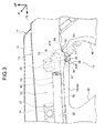
FIG. 3 is a perspective view showing the configuration of a vehicle rear end side including a rear end portion of a curtain airbag device pertaining to the embodiment of the present invention; -
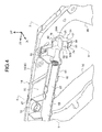
FIG. 4 is a perspective view showing, with a ceiling material being omitted, the configuration of the vehicle rear end side including the rear end portion of the curtain airbag device pertaining to the embodiment of the present invention; -
FIG. 5 is a perspective view showing, as seen obliquely from above in a vehicle rear direction, the configuration of the vehicle rear end side including the rear end portion of the curtain airbag device pertaining to the embodiment of the present invention; -
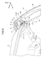
FIG. 6 is a perspective view showing, as seen obliquely from below in the vehicle rear direction, the configuration of the vehicle rear end side including the rear end portion of the curtain airbag device pertaining to the embodiment of the present invention; -
FIG. 7 is a perspective view showing, as seen obliquely from the right in the vehicle rear direction, the configuration of the vehicle rear end side including the rear end portion of the curtain airbag device pertaining to the embodiment of the present invention; -
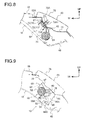
FIG. 8 is an enlarged longitudinal sectional view showing a cross section cut along line 8-8 ofFIG. 4 ; and -
FIG. 9 is an enlarged longitudinal sectional view showing a cross section cut along line 9-9 ofFIG. 4 . - An automobile ceiling material
provisional placement structure 10 and an automobile ceiling material installation method pertaining to an embodiment of the present invention will be described below usingFIG. 1 to FIG. 9 . In the drawings, arrow FR denotes a vehicle front direction, arrow UP denotes a vehicle up direction, and arrow IN denotes inward in a width direction width direction. - As shown in
FIG. 1 , in anautomobile 12 pertaining to the present embodiment, aroof 16 of avehicle body 14 is covered from apassenger compartment 20 side by a roof headlining 18 that is a ceiling material. The roof headlining 18 has a laminate structure in which a cover material comprising cloth is stuck to the surface of a core material comprising a resin material, for example, and the roof headlining 18 is molded and trim cut to a shape corresponding to theroof 16. - As shown in
FIG. 2 , clips 32, 34, 36, 38, and 40 are mounted on the reverse surface side of the roof headlining 18 in positions corresponding to accessories (vehicular parts) such assun visors 22, assist grips 24, arearview mirror 26, a passenger compartmentcentral light 28, and a frontseat illumination light 30. Further,plural clips 42 are lined up in the vehicle width direction and mounted on the vehicle rear side end portion of the roof headlining 18. Theseclips roof 16 and in roof side rails 46. Moreover, the accessories are fastened to theroof 16 and the roof side rails 46 by non-illustrated fasteners (screws, bolts, etc.), whereby the roof headlining 18 is secured to thevehicle body 14 together with the accessories. - As shown in
FIGS. 3 and5 to 9 ,curtain airbag devices 50 are disposed between the roof side rails 46 of thevehicle body 14 and the roof headlining 18. Thecurtain airbag devices 50 are disposed on both the right and left sides of the vehicle body, and other than the fact that they are bilaterally symmetrically formed, thecurtain airbag devices 50 are given basically the same configuration, so here the configuration of the vehicle body right side will be described and description in regard to the configuration of the vehicle body left side will be omitted. - The
curtain airbag devices 50 havecurtain airbags 52. Thecurtain airbags 52 are disposed between the roof side rails 46 and the roof headlining 18 in a state in which thecurtain airbags 52 have been folded into long shapes along the roof side rails 46 by what is called rolling, for example. The front end portions of thecurtain airbags 52 are disposed in the neighborhoods of A-pillars 54 (seeFIG. 1 ) of thevehicle body 14, and the rear end portions of thecurtain airbags 52 are disposed between C-pillars 58 and D-pillars 60 of thevehicle body 14. - Non-illustrated inflators secured to the roof side rails 46 in the vicinities of B-pillars 56 (see
FIG. 1 ) of thevehicle body 14 are connected to thecurtain airbags 52, and thecurtain airbags 52 inflate upon being supplied with gas generated by the inflators. Because of this, thecurtain airbags 52 deploy downward along the side portions of thepassenger compartment 20 while bending the vehicle width direction end sides of the roof headlining 18. - Resin covers 62 formed by a resin material are disposed between the
curtain airbags 52 and the roof side rails 46. The resin covers 62 havecover bodies 64 formed in long shapes along the roof side rails 46. Thecover bodies 64 are formed in cross-sectional C shapes having open portions 66 (seeFIG. 3 andFIG. 4 ) disposed in their vehicle width direction inner sides, and thecover bodies 64 partially cover (house inside) thecurtain airbags 52 in the folded state from theroof side rail 46 sides. For this reason, when the inflators have been actuated, thecurtain airbags 52 inflate and deploy via theopen portions 66 as thecover bodies 64 are subjected to a deployment reaction force of thecurtain airbags 52. Because of this, interference between thecurtain airbags 52 and the roof side rails 46 is prevented and thecurtain airbags 52 are protected. - Plural securing portions including securing
portions cover bodies 64. These securing portions project upward from thecover bodies 64. As shown inFIG. 8 ,attachment pieces 52A disposed on thecurtain airbags 52 are superposed on the vehicle width direction inner sides of the securingportions 67, and theattachment pieces 52A are locked together with the securingportions 67 byclips 71 toinner panels 74 of the roof side rails 46. Theclips 71 are configured bypins 72 andbushes 73. Thebushes 73 havetubular portions 73A, which penetrate the securingportions 67, theattachment pieces 52A, and theinner panels 74, andflange portions 73B, which are formed integrally with thetubular portions 73A, and plural elastic locking pieces 73A1 that elastically project outward in the radial direction of thetubular portions 73A are disposed on the side surfaces of thetubular portions 73A. When thetubular portions 73A are inserted into throughholes 75 in theinner panels 74, these elastic locking pieces 73A1 allow the insertion by elastically deforming inward in the radial direction of thetubular portions 73A, and in a state in which thepins 72 have been inserted inside thetubular portions 73A, the elastic deformation of the elastic locking pieces 73A1 inward in the radial direction of thetubular portions 73A is prevented. In this state, the elastic locking pieces 73A1 catch on the hole edge portions of the throughholes 75, whereby the tubular portions are prevented from slipping out of the throughholes 75, and theattachment pieces 52A and the securingportions 67 are held (secured) between theflange portions 73B and theinner panels 74. This securing structure is also the same for the securingportions 68 and other securing portions, whereby the resin covers 62 are secured together with thecurtain airbags 52 to the roof side rails 46. - In
FIG. 3 andFIG. 4 , for convenience of description, clips for securing the securingportions 68 to the roof side rails 46 are not illustrated. Further, inFIG. 8 and FIG. 9 , 76 denotes an outer panel of theroof side rail 46. Further, thecover bodies 64 are longitudinally divided in two, and their front portions and rear portions are coupled together via thecurtain airbags 52 in the folded state. That is, thecurtain airbags 52 are not covered by thecover bodies 64 at the divided portions, and thecover bodies 64 are bendable at the divided portions. Because of this, the work of carrying thecurtain airbag devices 50 into thepassenger compartment 20 becomes easy. - As shown in
FIG. 3 to FIG. 7 , the vehicle rear side end portions of thecover bodies 64 are disposed in the neighborhoods of the D-pillars 60 of thevehicle body 14, andreinforcement portions 78 formed like shelves are integrally disposed on the vehicle rear side end portions of thecover bodies 64. Thereinforcement portions 78 are disposed in proximity (adjacent) to the securingportions 68 disposed on the vehicle rear side end portions of thecover bodies 64 and configure part of thecover bodies 64. Thereinforcement portions 78 havevertical walls 80, which extend substantially in the vehicle up-and-down direction, andlower walls 82, which integrally project from the lower ends of thevertical walls 80 inward in the vehicle width direction and somewhat obliquely downward, so that thereinforcement portions 78 are formed in cross-sectional L shapes as seen from the vehicle front-and-rear direction. Receivingportions 84 for provisionally placing the roof headlining 18 are integrally connected to thereinforcement portions 78. - The receiving
portions 84 are disposed on the vehicle rear sides of the vehicle rear side end portions of the curtain airbags 52-that is, in the regions of thecover bodies 64 of the resin covers 62 where thecurtain airbags 52 are not housed-and are disposed in proximity to the vehicle rear sides of the securingportions 68. The receivingportions 84 havebody portions 84A, which integrally extend from the vehicle width direction outside sections of thereinforcement portions 78 outward in the vehicle width direction and downward, andprovisional placement claws 84B, which extend from the lower end portions of thebody portions 84A inward in the vehicle width direction. The receivingportions 84 will be described in detail below. - As shown in
FIG. 5 , thebody portions 84A havefront walls 86 andrear walls 88 formed in substantially triangular shapes as seen from the vehicle front-and-rear direction. The upper portions of thefront walls 86 andrear walls 88 are disposed between thereinforcement portions 78 and the roof side rails 46, and the vehicle width direction inside end portions of the upper portions of thefront walls 86 andrear walls 88 are integrally connected to the vehicle width direction outside surfaces of thevertical walls 80 of thereinforcement portions 78 and the vehicle width direction outside sections of the undersurfaces of thelower walls 82 of thereinforcement portions 78. Further, the vehicle width direction outside end portions of the upper portions of thefront walls 86 andrear walls 88 are inclined along theinner panels 74 of the roof side rails 46 and are in contact with theinner panels 74. - The lower portions of the
front walls 86 andrear walls 88 are formed in such a way that their dimension along the vehicle width direction becomes smaller toward their lower end sides, and the vehicle width direction inside end portions of the lower portions of thefront walls 86 andrear walls 88 are integrally coupled together in the vehicle front-and-rear direction byinner walls 90. Because of this, thebody portions 84A are formed in cross-sectional substantial U shapes whose vehicle width direction outer sides are open as seen from the vehicle up-and-down direction. Theinner walls 90 are disposed substantially along the vehicle up-and-down direction, and the upper end portions of theinner walls 90 are integrally connected to the undersurfaces of thelower walls 82 of the reinforcement portions 78 (seeFIG. 9 ). - As shown in
FIG. 4 , theprovisional placement claws 84B are formed as a result of the lower end portions of thefront walls 86 andrear walls 88 projecting further inward in the vehicle width direction than theinner walls 90 and the upper ends of those projecting sections being integrally coupled together byhorizontal walls 92. Thehorizontal walls 92 are disposed substantially horizontally with respect to thevehicle body 14, and the vehicle width direction outside end portions of thehorizontal walls 92 are integrally connected to theinner walls 90. Further, the projecting sections of thefront walls 86 andrear walls 88 are formed in triangular shapes as seen from the vehicle front-and-rear direction, and the vehicle width direction inside end portions of the projecting sections are made to serve asguide portions 94 obliquely inclined downward and outward in the vehicle width direction. - The receiving
portions 84 correspond toengagement pieces 18A (seeFIGS. 2 ,3 ,5 to 7, and 9) disposed on both vehicle width direction end portions of the vehicle rear side end portion of the roof headlining 18. As shown inFIG. 9 , theengagement pieces 18A are formed as a result of the vehicle width direction end portions (portions in contact with roof side inner garnishes 48) of the roof headlining 18 partially extending (being lengthened) outward in the vehicle width direction. InFIG. 5 to FIG. 7 , 18B denotes support pieces that support the middle portions of harnesses connected to the inflators, and 18C denotes looseness prevention pieces (not illustrated inFIG. 2 ) that prevent looseness of the rear end portions of the roof headlining 18. - Here, in the present embodiment, when the roof headlining 18 is to be installed in the
vehicle body 14, first, thecurtain airbag devices 50 are secured to the roof side rails 46 by theclips 71 and so forth. Thereafter, the roof headlining 18 is carried into thepassenger compartment 20 via anopen portion 96 in the front portion of thepassenger compartment 20. Then, the roof headlining 18 is lifted upward inside thepassenger compartment 20, whereby theengagement pieces 18A of the roof headlining 18 slide against theguide portions 94 of theprovisional placement claws 84B. Because of this, theengagement pieces 18A are guided on theguide portions 94 and ride up onto the upper surfaces of thehorizontal walls 92, whereby the rear end side of the roof headlining 18 is provisionally placed (supported) on theprovisional placement claws 84B of the receivingportions 84. Thereafter, theclips roof 16 of thevehicle body 14, whereby the front end side of the roof headlining 18 is supported on thevehicle body 14. In this state, the roof headlining 18 is disposed substantially horizontally in the neighborhood below the normal installation position where the roof headlining 18 is installed in thevehicle body 14. In this state, theother clips roof 16 and the roof side rails 46, andsun visor brackets 23 and so forth are fastened to theroof 16 and the roof side rails 46 by fasteners (screws, bolts, etc.), whereby the roof headlining 18 is secured to thevehicle body 14. - Next, the action and effects of the present embodiment will be described.
- In the present embodiment, the receiving
portions 84 for provisionally placing the roof headlining 18 are disposed on the existing resin covers 62 covering thecurtain airbags 52, so it is not necessary to dispose dedicated receiving portions. Because of this, an increase in cost can be suppressed. Moreover, the resin covers 62 are formed in long shapes along the roof side rails 46, so the degree of freedom of the setting positions of the receivingportions 84 disposed on the resin covers 62 can be improved. Because of this, workability when installing the roof headlining 18 in thevehicle body 14 can be improved. - That is, in the present embodiment, because the degree of freedom of the setting positions of the receiving
portions 84 is improved as described above, the receivingportions 84 are disposed on the vehicle rear side end portions of the resin covers 62. Because of this, theengagement pieces 18A disposed on the rear end side of the roof headlining 18 can be provisionally placed on the receivingportions 84 disposed on the vehicle rear side end portions of the resin covers 62. In this state, when the front end side of the roof headlining 18 is locked to thevehicle body 14 by theclips vehicle body 14. Because of this, the work of attaching (the work of fastening) thesun visor brackets 23 and the assist grips 24 to thevehicle body 14 thereafter-that is, the work of securing the roof headlining 18 to thevehicle body 14 using these members-can be made easy. - Further, in the present embodiment, the receiving
portions 84 of the resin covers 62 are disposed on the vehicle rear sides of the vehicle rear side end portions of thecurtain airbags 52. For this reason, when thecurtain airbags 52 inflate and deploy downward, the receivingportions 84 do not interfere with thecurtain airbags 52, which is preferred. In other words, in a case where the receiving portions have been set in the regions of thecover bodies 64 of the resin covers 62 where thecurtain airbags 52 are housed, restrictions arise on the shape of the receiving portions and the shape of the roof headlining 18 in order to prevent interference between thecurtain airbags 52 and the receiving portions, but in the present embodiment, such restrictions can be avoided. Because of this, interference between thecurtain airbags 52 and the receiving portions can be prevented while making workability when performing the work of provisionally placing the roof headlining 18 good. - Moreover, in the present embodiment, the receiving
portions 84 of the resin covers 62 are disposed in proximity to the securingportions 68 for securing the resin covers 62 to the roof side rails 46. Because of this, when the roof headlining 18 has been provisionally placed on the receivingportions 84, the mass of the roof headlining 18 can be supported well by the roof side rails 46 while suppressing deformation of the resin covers 62. - Furthermore, in the present embodiment, as shown in
FIG. 9 , the receivingportions 84 extend downward from the vehicle width direction outside sections (the sections on theroof side rail 46 sides) of thecover bodies 64 of the resin covers 62. Additionally, theengagement pieces 18A (the vehicle width direction end portions) of the roof headlining 18 are provisionally placed on the upper surfaces of thehorizontal walls 92 of theprovisional placement claws 84B disposed on the lower end sides of the receivingportions 84. Because of this, spaces for disposing the receivingportions 84 can be easily ensured in the limited spaces between the roof side rails 46 and the roof headlining 18. - Further, in the present embodiment, the vehicle width direction outside end portions of the upper portions of the receiving
portions 84 are in contact with theinner panels 74 of the roof side rails 46. Because of this, when the roof side rails 46 have been provisionally placed on the receivingportions 84, the receivingportions 84 can be prevented or suppressed from deforming toward the roof side rails 46. Consequently, by moderately weakening the receivingportions 84, it becomes possible to reduce the weight of the receivingportions 84. - Further, in the present embodiment, the vehicle width direction inside end portions of the
provisional placement claws 84B disposed on the receivingportions 84 are made to serve as theguide portions 94 inclined upward and inward in the vehicle width direction. For this reason, when provisionally placing the roof headlining 18 on the upper surfaces of thehorizontal walls 92 of theprovisional placement claws 84B, theengagement pieces 18A of the roof headlining 18 can be guided to the upper surfaces of theprovisional placement claws 84B by allowing theengagement pieces 18A to slide against the guide portions 94 (seeFIGS. 3 and4 ). That is, even if the direction in which the roof headlining 18 is lifted up varies somewhat, the lift-up direction of the roof headlining 18 can be guided by theguide portions 94, so the work of provisionally placing the roof headlining 18 can be made easy. - Moreover, in the above embodiment, the shelf-
like reinforcement portions 78 are disposed on the vehicle rear side end portions of the resin covers 62, and the receivingportions 84 extend from thereinforcement portions 78, so the resin covers 62 can be prevented or effectively suppressed from deforming due to the load input from the roof headlining 18 to the receivingportions 84. - Further, in the above embodiment, the
body portions 84A of the receivingportions 84 are formed in cross-sectional substantial U shapes whose vehicle width direction outer sides are open as seen from the vehicle up-and-down direction, so a balance between reducing the weight of the receivingportions 84 and ensuring the stiffness of the receivingportions 84 can be achieved. - The above embodiment was given a configuration in which the receiving
portions 84 were disposed in proximity to the vehicle rear sides of the securingportions 68, but the embodiment is not limited to this and may also be given a configuration in which the receivingportions 84 are disposed below the securingportions 68. Because of this, deformation of the resin covers 62 when the roof headlining 18 has been provisionally placed on the receivingportions 84 can be kept to a minimum, so by moderately weakening the sections of the resin covers 62 between the receivingportions 84 and the securingportions 68, the weight of the resin covers 62 can be reduced. - Further, the above embodiment was given a configuration in which the vehicle width direction inside end portions of the
provisional placement claws 84B were made to serve as theguide portions 94 obliquely inclined downward and outward in the vehicle width direction, but the embodiment is not limited to this and may also be given a configuration in which theguide portions 94 are omitted. That is, the embodiment may also be given a configuration in which the vehicle width direction inside end portions of theprovisional placement claws 84B are formed substantially along the vehicle up-and-down direction. - Further, the above embodiment was given a configuration in which the vehicle width direction outside end portions of the receiving
portions 84 were in contact with theinner panels 74 of the roof side rails 46, but the embodiment is not limited to this and may also be given a configuration in which the receivingportions 84 are disposed away from theinner panels 74. - Moreover, the above embodiment was given a configuration in which the receiving
portions 84 extended downward from the vehicle width direction outside end portions of thereinforcement portions 78 configuring part of thecover bodies 64, but the embodiment is not limited to this, and the direction in which the receivingportions 84 extend can be appropriately changed. - Further, the above embodiment was given a configuration in which the
provisional placement claws 84B projecting inward in the vehicle width direction were disposed on the lower end portions of the receivingportions 84 and theengagement pieces 18A (the vehicle width direction end portions) of the roof headlining 18 were provisionally placed on the upper surfaces of theprovisional placement claws 84B, but the embodiment is not limited to this and may also be given a configuration in which theprovisional placement claws 84B are omitted. In this case, for example, the embodiment may be given a configuration in which recessed portions are formed on the lower end sides of the receivingportions 84 and the vehicle width direction end portions of the roof headlining 18 are inserted and provisionally placed in the recessed portions. - Further, the above embodiment was given a configuration in which the
reinforcement portions 78 were disposed on the vehicle rear side end portions of thecover bodies 64, but the embodiment is not limited to this and may also be given a configuration in which thereinforcement portions 78 are omitted. - Moreover, the above embodiment was given a configuration in which the receiving
portions 84 were disposed in proximity to the securingportions 68 for securing the resin covers 62 to the roof side rails 46, but the embodiment is not limited to this and may also be given a configuration in which the receivingportions 84 are disposed away from the securingportions 68. - Further, the above embodiment was given a configuration in which the receiving
portions 84 were disposed on the vehicle rear sides of the vehicle rear side end portions of thecurtain airbags 52 in the folded state on the vehicle rear side end portions of the resin covers 62, but the embodiment is not limited to this, and where the receivingportions 84 are disposed on the resin covers 62 can be appropriately changed. However, even in this case, it is preferred that the receivingportions 84 be disposed in the regions of thecover bodies 64 where thecurtain airbags 52 are not housed. - In addition, the present invention can be changed and implemented in a variety of ways without departing from the gist thereof. Further, it goes without saying that the scope of rights of the present invention is not limited to the above embodiment.
Claims (9)
- An automobile ceiling material provisional placement structure comprising:a ceiling material that configures a lining of a ceiling of a passenger compartment;curtain airbags that are disposed between roof side rails of a vehicle body and the ceiling material in a state in which the curtain airbags are folded in long shapes along the roof side rails, with the curtain airbags inflating upon being supplied with gas generated by inflators, whereby the curtain airbags deploy downward while bending vehicle width direction end sides of the ceiling material; andresin covers that are formed in long shapes along the roof side rails, are disposed between the roof side rails and the curtain airbags, cover the curtain airbags in the folded state from the roof side rail sides, and have disposed thereon receiving portions capable of provisionally placing vehicle width direction end portions of the ceiling material when the ceiling material is installed in the vehicle body.
- The automobile ceiling material provisional placement structure according to claim 1, wherein the receiving portions are disposed on vehicle rear side end portions of the resin covers.
- The automobile ceiling material provisional placement structure according to claim 2, wherein the receiving portions are disposed on vehicle rear sides of vehicle rear side end portions of the curtain airbags in the folded state.
- The automobile ceiling material provisional placement structure according to any one of claim 1 to claim 3, wherein the receiving portions are disposed in proximity to securing portions for securing the resin covers to the roof side rails.
- The automobile ceiling material provisional placement structure according to any one of claim 1 to claim 4, wherein the receiving portions extend downward from vehicle width direction outside sections of cover bodies of the resin covers covering the curtain airbags, provisional placement claws projecting inward in the vehicle width direction are disposed on lower end sides of the receiving portions, and the vehicle width direction end portions of the ceiling material are provisionally placed on upper surfaces of the provisional placement claws.
- The automobile ceiling material provisional placement structure according to any one of claim 1 to claim 5, wherein vehicle width direction outside end portions of the receiving portions are in contact with the roof side rails.
- The automobile ceiling material provisional placement structure according to claim 5, wherein vehicle width direction inside end portions of the provisional placement claws are made to serve as guide portions obliquely inclined downward and outward in the vehicle width direction.
- The automobile ceiling material provisional placement structure according to claim 4, wherein the receiving portions are disposed below the securing portions.
- An automobile ceiling material installation method comprising:attaching long resin covers covering curtain airbags folded in long shapes to roof side rails;thereafter provisionally placing vehicle width direction end portions of a ceiling material of a passenger compartment on receiving portions disposed on the resin covers; andsecuring the ceiling material to a vehicle body via plural vehicular parts including sun visor brackets and assist grips in the provisionally placed state.
Applications Claiming Priority (1)
| Application Number | Priority Date | Filing Date | Title |
|---|---|---|---|
| PCT/JP2011/060555 WO2012150634A1 (en) | 2011-05-02 | 2011-05-02 | Automotive ceiling material temporarily locating structure, and method of assembling automotive ceiling material |
Publications (3)
| Publication Number | Publication Date |
|---|---|
| EP2705987A1 true EP2705987A1 (en) | 2014-03-12 |
| EP2705987A4 EP2705987A4 (en) | 2014-04-23 |
| EP2705987B1 EP2705987B1 (en) | 2015-06-24 |
Family
ID=47107827
Family Applications (1)
| Application Number | Title | Priority Date | Filing Date |
|---|---|---|---|
| EP11864799.9A Not-in-force EP2705987B1 (en) | 2011-05-02 | 2011-05-02 | Automotive ceiling material temporarily locating structure, and method of assembling automotive ceiling material |
Country Status (5)
| Country | Link |
|---|---|
| US (1) | US8833797B2 (en) |
| EP (1) | EP2705987B1 (en) |
| JP (1) | JP5660206B2 (en) |
| CN (1) | CN103476637B (en) |
| WO (1) | WO2012150634A1 (en) |
Cited By (2)
| Publication number | Priority date | Publication date | Assignee | Title |
|---|---|---|---|---|
| WO2021083819A1 (en) * | 2019-10-30 | 2021-05-06 | Man Truck & Bus Se | Lining a roof structure of a driver's cab of a commercial vehicle |
| FR3125499A1 (en) * | 2021-07-23 | 2023-01-27 | Psa Automobiles Sa | INTERFACE PIECE BETWEEN A TRIM AND A VEHICLE PILLAR LINING |
Families Citing this family (11)
| Publication number | Priority date | Publication date | Assignee | Title |
|---|---|---|---|---|
| JP5639131B2 (en) * | 2012-09-07 | 2014-12-10 | 富士重工業株式会社 | Arrangement structure of curtain airbag device |
| JP6107629B2 (en) * | 2013-12-06 | 2017-04-05 | 豊田合成株式会社 | Head protection airbag device |
| US10005508B2 (en) * | 2014-04-24 | 2018-06-26 | Ford Global Technologies, Llc | Flexible headliner assembly table |
| US9475449B2 (en) * | 2014-12-23 | 2016-10-25 | Toyota Motor Engineering & Manufacturing North America, Inc. | Headliner assemblies having tethered support structure |
| JP6158870B2 (en) * | 2015-08-05 | 2017-07-05 | 本田技研工業株式会社 | Airbag device |
| JP6439193B2 (en) * | 2016-07-14 | 2018-12-19 | 本田技研工業株式会社 | Side curtain airbag device |
| JP6954235B2 (en) * | 2018-06-25 | 2021-10-27 | 豊田合成株式会社 | Head protection airbag device |
| JP7390206B2 (en) * | 2020-02-18 | 2023-12-01 | トヨタ紡織株式会社 | Roof lining temporary retention structure and temporary retention member |
| US11878637B2 (en) * | 2021-03-30 | 2024-01-23 | Honda Motor Co., Ltd. | Attachment structure for a vehicle roof lining |
| JP7584345B2 (en) * | 2021-04-05 | 2024-11-15 | トヨタ自動車東日本株式会社 | Vehicle upper structure |
| US11865990B2 (en) * | 2022-05-25 | 2024-01-09 | Autoliv Asp, Inc. | Ramp bracket for a curtain airbag |
Family Cites Families (25)
| Publication number | Priority date | Publication date | Assignee | Title |
|---|---|---|---|---|
| JP2548373Y2 (en) * | 1990-08-02 | 1997-09-17 | オートリブ デベロップメント アクテボラゲット | Airbag device |
| US5941558A (en) * | 1997-06-09 | 1999-08-24 | Textron Automotive Company Inc. | Apparatus for deploying an airbag through a hard panel |
| US6955376B1 (en) * | 1997-06-09 | 2005-10-18 | Collins & Aikman Products Co. | Apparatus for deploying an air bag through a hard panel |
| JPH111147A (en) | 1997-06-13 | 1999-01-06 | Kasai Kogyo Co Ltd | Roof trim for vehicle |
| JP3007070B2 (en) * | 1998-03-19 | 2000-02-07 | 株式会社イノアックコーポレーション | Side rail shock absorber for automobile ceiling |
| JP2001206158A (en) | 2000-01-27 | 2001-07-31 | Piolax Inc | Vehicle roof trim mounting structure and mounting method |
| JP3864703B2 (en) | 2001-01-11 | 2007-01-10 | 豊田合成株式会社 | Airbag and its wrapping method |
| JP2002362248A (en) | 2001-06-06 | 2002-12-18 | Toyota Industries Corp | Ceiling of automobile |
| JP2003063351A (en) * | 2001-06-11 | 2003-03-05 | Honda Motor Co Ltd | Passenger constraint device |
| JP2003137038A (en) | 2001-11-05 | 2003-05-14 | Hino Motors Ltd | Car ceiling structure |
| JP2003226199A (en) * | 2002-02-06 | 2003-08-12 | Honda Motor Co Ltd | Body structure with airbag for head protection |
| JP3849563B2 (en) * | 2002-03-29 | 2006-11-22 | 三菱自動車工業株式会社 | Vehicle occupant protection device |
| JP4458228B2 (en) | 2003-08-21 | 2010-04-28 | 日産自動車株式会社 | Belt type continuously variable transmission |
| US7334309B2 (en) | 2003-09-11 | 2008-02-26 | Inalfa Aftermarket Group B.V. | Method of mounting a roof assembly into the interior of a vehicle; as well as such roof assembly and a vehicle |
| JP2006096076A (en) * | 2004-09-28 | 2006-04-13 | Mazda Motor Corp | Layout structure of curtain airbag |
| JP4389817B2 (en) | 2005-03-15 | 2009-12-24 | トヨタ車体株式会社 | Vehicle ceiling material |
| US20060267315A1 (en) * | 2005-05-26 | 2006-11-30 | Trw Vehicle Safety Systems Inc. | Bracket assembly for an inflatable curtain |
| JP4864660B2 (en) * | 2006-06-23 | 2012-02-01 | 本田技研工業株式会社 | Curtain airbag device and airbag module |
| US7651121B2 (en) * | 2006-09-25 | 2010-01-26 | Gm Global Technology Operations, Inc. | Molding for vehicle headliner |
| JP5034455B2 (en) * | 2006-11-24 | 2012-09-26 | マツダ株式会社 | Interior structure of a vehicle equipped with a curtain airbag device |
| EP1925510B1 (en) | 2006-11-24 | 2012-08-15 | Mazda Motor Corporation | Interior structure of vehicle equipped with curtain airbag device |
| JP5204993B2 (en) * | 2007-06-11 | 2013-06-05 | 本田技研工業株式会社 | Arrangement structure of interior parts of vehicle |
| JP5180554B2 (en) | 2007-10-04 | 2013-04-10 | 本田技研工業株式会社 | Airbag device for vehicle |
| US8096574B2 (en) | 2007-10-04 | 2012-01-17 | Honda Motor Co., Ltd. | Air bag system for vehicle |
| US8033569B2 (en) | 2008-08-08 | 2011-10-11 | Mazda Motor Corporation | Interior structure of vehicle equipped with curtain airbag |
-
2011
- 2011-05-02 WO PCT/JP2011/060555 patent/WO2012150634A1/en not_active Ceased
- 2011-05-02 CN CN201180070053.5A patent/CN103476637B/en not_active Expired - Fee Related
- 2011-05-02 JP JP2013513057A patent/JP5660206B2/en not_active Expired - Fee Related
- 2011-05-02 EP EP11864799.9A patent/EP2705987B1/en not_active Not-in-force
- 2011-05-02 US US14/005,342 patent/US8833797B2/en active Active
Cited By (2)
| Publication number | Priority date | Publication date | Assignee | Title |
|---|---|---|---|---|
| WO2021083819A1 (en) * | 2019-10-30 | 2021-05-06 | Man Truck & Bus Se | Lining a roof structure of a driver's cab of a commercial vehicle |
| FR3125499A1 (en) * | 2021-07-23 | 2023-01-27 | Psa Automobiles Sa | INTERFACE PIECE BETWEEN A TRIM AND A VEHICLE PILLAR LINING |
Also Published As
| Publication number | Publication date |
|---|---|
| CN103476637A (en) | 2013-12-25 |
| JP5660206B2 (en) | 2015-01-28 |
| WO2012150634A1 (en) | 2012-11-08 |
| EP2705987A4 (en) | 2014-04-23 |
| EP2705987B1 (en) | 2015-06-24 |
| US8833797B2 (en) | 2014-09-16 |
| US20140042734A1 (en) | 2014-02-13 |
| CN103476637B (en) | 2016-04-27 |
| JPWO2012150634A1 (en) | 2014-07-28 |
Similar Documents
| Publication | Publication Date | Title |
|---|---|---|
| EP2705987B1 (en) | Automotive ceiling material temporarily locating structure, and method of assembling automotive ceiling material | |
| JP4720449B2 (en) | Mounting structure for interior materials around the front pillar of an automobile | |
| KR100895128B1 (en) | Side curtain airbag unit | |
| US7934746B2 (en) | Motor vehicle with an A-column and airbag incorporated therein | |
| CN214874691U (en) | Airbag for sunroof of vehicle | |
| JP2009078716A (en) | Airbag device | |
| JP2009056873A (en) | Arrangement structure of curtain airbag device | |
| US8727373B2 (en) | Curtain shield airbag mounting structure | |
| JP3879553B2 (en) | Vehicle occupant protection device | |
| JP5046830B2 (en) | Airbag device | |
| JP2011218994A (en) | Curtain air bag device for vehicle | |
| JP4833099B2 (en) | Arrangement structure of airbag device | |
| CN1282567C (en) | occupant protection device | |
| JP4974938B2 (en) | Airbag device | |
| JP5267903B2 (en) | Vehicle pillar trim mounting structure | |
| JP2010095225A (en) | Incorrect attachment prevention structure for front pillar trim | |
| JP2009078717A (en) | Airbag device | |
| JP7189497B2 (en) | Vehicle upper interior structure | |
| JP5166948B2 (en) | Airbag device | |
| JP2008012976A (en) | Airbag device | |
| JP2016120873A (en) | Inflation structure for curtain airbag for vehicle | |
| JP4933929B2 (en) | Airbag cover body and airbag device | |
| JP2009241895A (en) | Airbag device | |
| JP4974933B2 (en) | Airbag device | |
| JP5005408B2 (en) | Airbag device |
Legal Events
| Date | Code | Title | Description |
|---|---|---|---|
| PUAI | Public reference made under article 153(3) epc to a published international application that has entered the european phase |
Free format text: ORIGINAL CODE: 0009012 |
|
| 17P | Request for examination filed |
Effective date: 20130916 |
|
| AK | Designated contracting states |
Kind code of ref document: A1 Designated state(s): AL AT BE BG CH CY CZ DE DK EE ES FI FR GB GR HR HU IE IS IT LI LT LU LV MC MK MT NL NO PL PT RO RS SE SI SK SM TR |
|
| A4 | Supplementary search report drawn up and despatched |
Effective date: 20140320 |
|
| DAX | Request for extension of the european patent (deleted) | ||
| GRAP | Despatch of communication of intention to grant a patent |
Free format text: ORIGINAL CODE: EPIDOSNIGR1 |
|
| RIC1 | Information provided on ipc code assigned before grant |
Ipc: B60R 21/214 20110101ALI20141114BHEP Ipc: B60R 21/213 20110101ALI20141114BHEP Ipc: B60R 21/217 20110101ALI20141114BHEP Ipc: B60R 13/02 20060101AFI20141114BHEP |
|
| INTG | Intention to grant announced |
Effective date: 20141208 |
|
| GRAS | Grant fee paid |
Free format text: ORIGINAL CODE: EPIDOSNIGR3 |
|
| GRAA | (expected) grant |
Free format text: ORIGINAL CODE: 0009210 |
|
| AK | Designated contracting states |
Kind code of ref document: B1 Designated state(s): AL AT BE BG CH CY CZ DE DK EE ES FI FR GB GR HR HU IE IS IT LI LT LU LV MC MK MT NL NO PL PT RO RS SE SI SK SM TR |
|
| REG | Reference to a national code |
Ref country code: GB Ref legal event code: FG4D |
|
| REG | Reference to a national code |
Ref country code: CH Ref legal event code: EP |
|
| REG | Reference to a national code |
Ref country code: AT Ref legal event code: REF Ref document number: 732742 Country of ref document: AT Kind code of ref document: T Effective date: 20150715 |
|
| REG | Reference to a national code |
Ref country code: IE Ref legal event code: FG4D |
|
| REG | Reference to a national code |
Ref country code: DE Ref legal event code: R096 Ref document number: 602011017404 Country of ref document: DE |
|
| PG25 | Lapsed in a contracting state [announced via postgrant information from national office to epo] |
Ref country code: FI Free format text: LAPSE BECAUSE OF FAILURE TO SUBMIT A TRANSLATION OF THE DESCRIPTION OR TO PAY THE FEE WITHIN THE PRESCRIBED TIME-LIMIT Effective date: 20150624 Ref country code: LT Free format text: LAPSE BECAUSE OF FAILURE TO SUBMIT A TRANSLATION OF THE DESCRIPTION OR TO PAY THE FEE WITHIN THE PRESCRIBED TIME-LIMIT Effective date: 20150624 Ref country code: HR Free format text: LAPSE BECAUSE OF FAILURE TO SUBMIT A TRANSLATION OF THE DESCRIPTION OR TO PAY THE FEE WITHIN THE PRESCRIBED TIME-LIMIT Effective date: 20150624 Ref country code: NO Free format text: LAPSE BECAUSE OF FAILURE TO SUBMIT A TRANSLATION OF THE DESCRIPTION OR TO PAY THE FEE WITHIN THE PRESCRIBED TIME-LIMIT Effective date: 20150924 |
|
| REG | Reference to a national code |
Ref country code: AT Ref legal event code: MK05 Ref document number: 732742 Country of ref document: AT Kind code of ref document: T Effective date: 20150624 |
|
| REG | Reference to a national code |
Ref country code: LT Ref legal event code: MG4D |
|
| PG25 | Lapsed in a contracting state [announced via postgrant information from national office to epo] |
Ref country code: BG Free format text: LAPSE BECAUSE OF FAILURE TO SUBMIT A TRANSLATION OF THE DESCRIPTION OR TO PAY THE FEE WITHIN THE PRESCRIBED TIME-LIMIT Effective date: 20150924 Ref country code: LV Free format text: LAPSE BECAUSE OF FAILURE TO SUBMIT A TRANSLATION OF THE DESCRIPTION OR TO PAY THE FEE WITHIN THE PRESCRIBED TIME-LIMIT Effective date: 20150624 Ref country code: GR Free format text: LAPSE BECAUSE OF FAILURE TO SUBMIT A TRANSLATION OF THE DESCRIPTION OR TO PAY THE FEE WITHIN THE PRESCRIBED TIME-LIMIT Effective date: 20150925 Ref country code: RS Free format text: LAPSE BECAUSE OF FAILURE TO SUBMIT A TRANSLATION OF THE DESCRIPTION OR TO PAY THE FEE WITHIN THE PRESCRIBED TIME-LIMIT Effective date: 20150624 |
|
| REG | Reference to a national code |
Ref country code: NL Ref legal event code: MP Effective date: 20150624 |
|
| PG25 | Lapsed in a contracting state [announced via postgrant information from national office to epo] |
Ref country code: EE Free format text: LAPSE BECAUSE OF FAILURE TO SUBMIT A TRANSLATION OF THE DESCRIPTION OR TO PAY THE FEE WITHIN THE PRESCRIBED TIME-LIMIT Effective date: 20150624 |
|
| REG | Reference to a national code |
Ref country code: DE Ref legal event code: R084 Ref document number: 602011017404 Country of ref document: DE |
|
| PG25 | Lapsed in a contracting state [announced via postgrant information from national office to epo] |
Ref country code: RO Free format text: LAPSE BECAUSE OF NON-PAYMENT OF DUE FEES Effective date: 20150624 Ref country code: CZ Free format text: LAPSE BECAUSE OF FAILURE TO SUBMIT A TRANSLATION OF THE DESCRIPTION OR TO PAY THE FEE WITHIN THE PRESCRIBED TIME-LIMIT Effective date: 20150624 Ref country code: ES Free format text: LAPSE BECAUSE OF FAILURE TO SUBMIT A TRANSLATION OF THE DESCRIPTION OR TO PAY THE FEE WITHIN THE PRESCRIBED TIME-LIMIT Effective date: 20150624 Ref country code: PT Free format text: LAPSE BECAUSE OF FAILURE TO SUBMIT A TRANSLATION OF THE DESCRIPTION OR TO PAY THE FEE WITHIN THE PRESCRIBED TIME-LIMIT Effective date: 20151026 Ref country code: AT Free format text: LAPSE BECAUSE OF FAILURE TO SUBMIT A TRANSLATION OF THE DESCRIPTION OR TO PAY THE FEE WITHIN THE PRESCRIBED TIME-LIMIT Effective date: 20150624 Ref country code: PL Free format text: LAPSE BECAUSE OF FAILURE TO SUBMIT A TRANSLATION OF THE DESCRIPTION OR TO PAY THE FEE WITHIN THE PRESCRIBED TIME-LIMIT Effective date: 20150624 Ref country code: SK Free format text: LAPSE BECAUSE OF FAILURE TO SUBMIT A TRANSLATION OF THE DESCRIPTION OR TO PAY THE FEE WITHIN THE PRESCRIBED TIME-LIMIT Effective date: 20150624 Ref country code: IS Free format text: LAPSE BECAUSE OF FAILURE TO SUBMIT A TRANSLATION OF THE DESCRIPTION OR TO PAY THE FEE WITHIN THE PRESCRIBED TIME-LIMIT Effective date: 20151024 |
|
| REG | Reference to a national code |
Ref country code: GB Ref legal event code: 746 Effective date: 20160226 |
|
| REG | Reference to a national code |
Ref country code: DE Ref legal event code: R097 Ref document number: 602011017404 Country of ref document: DE |
|
| REG | Reference to a national code |
Ref country code: FR Ref legal event code: PLFP Year of fee payment: 6 |
|
| PG25 | Lapsed in a contracting state [announced via postgrant information from national office to epo] |
Ref country code: IT Free format text: LAPSE BECAUSE OF FAILURE TO SUBMIT A TRANSLATION OF THE DESCRIPTION OR TO PAY THE FEE WITHIN THE PRESCRIBED TIME-LIMIT Effective date: 20150624 Ref country code: DK Free format text: LAPSE BECAUSE OF FAILURE TO SUBMIT A TRANSLATION OF THE DESCRIPTION OR TO PAY THE FEE WITHIN THE PRESCRIBED TIME-LIMIT Effective date: 20150624 |
|
| PLBE | No opposition filed within time limit |
Free format text: ORIGINAL CODE: 0009261 |
|
| STAA | Information on the status of an ep patent application or granted ep patent |
Free format text: STATUS: NO OPPOSITION FILED WITHIN TIME LIMIT |
|
| 26N | No opposition filed |
Effective date: 20160329 |
|
| PG25 | Lapsed in a contracting state [announced via postgrant information from national office to epo] |
Ref country code: SI Free format text: LAPSE BECAUSE OF FAILURE TO SUBMIT A TRANSLATION OF THE DESCRIPTION OR TO PAY THE FEE WITHIN THE PRESCRIBED TIME-LIMIT Effective date: 20150624 Ref country code: BE Free format text: LAPSE BECAUSE OF NON-PAYMENT OF DUE FEES Effective date: 20160531 |
|
| PG25 | Lapsed in a contracting state [announced via postgrant information from national office to epo] |
Ref country code: BE Free format text: LAPSE BECAUSE OF FAILURE TO SUBMIT A TRANSLATION OF THE DESCRIPTION OR TO PAY THE FEE WITHIN THE PRESCRIBED TIME-LIMIT Effective date: 20150624 Ref country code: LU Free format text: LAPSE BECAUSE OF FAILURE TO SUBMIT A TRANSLATION OF THE DESCRIPTION OR TO PAY THE FEE WITHIN THE PRESCRIBED TIME-LIMIT Effective date: 20160502 |
|
| REG | Reference to a national code |
Ref country code: CH Ref legal event code: PL |
|
| PG25 | Lapsed in a contracting state [announced via postgrant information from national office to epo] |
Ref country code: CH Free format text: LAPSE BECAUSE OF NON-PAYMENT OF DUE FEES Effective date: 20160531 Ref country code: LI Free format text: LAPSE BECAUSE OF NON-PAYMENT OF DUE FEES Effective date: 20160531 |
|
| REG | Reference to a national code |
Ref country code: IE Ref legal event code: MM4A |
|
| REG | Reference to a national code |
Ref country code: FR Ref legal event code: PLFP Year of fee payment: 7 |
|
| PG25 | Lapsed in a contracting state [announced via postgrant information from national office to epo] |
Ref country code: IE Free format text: LAPSE BECAUSE OF NON-PAYMENT OF DUE FEES Effective date: 20160502 |
|
| PG25 | Lapsed in a contracting state [announced via postgrant information from national office to epo] |
Ref country code: NL Free format text: LAPSE BECAUSE OF FAILURE TO SUBMIT A TRANSLATION OF THE DESCRIPTION OR TO PAY THE FEE WITHIN THE PRESCRIBED TIME-LIMIT Effective date: 20150624 Ref country code: SE Free format text: LAPSE BECAUSE OF FAILURE TO SUBMIT A TRANSLATION OF THE DESCRIPTION OR TO PAY THE FEE WITHIN THE PRESCRIBED TIME-LIMIT Effective date: 20150624 |
|
| REG | Reference to a national code |
Ref country code: FR Ref legal event code: PLFP Year of fee payment: 8 |
|
| PG25 | Lapsed in a contracting state [announced via postgrant information from national office to epo] |
Ref country code: HU Free format text: LAPSE BECAUSE OF FAILURE TO SUBMIT A TRANSLATION OF THE DESCRIPTION OR TO PAY THE FEE WITHIN THE PRESCRIBED TIME-LIMIT; INVALID AB INITIO Effective date: 20110502 Ref country code: SM Free format text: LAPSE BECAUSE OF FAILURE TO SUBMIT A TRANSLATION OF THE DESCRIPTION OR TO PAY THE FEE WITHIN THE PRESCRIBED TIME-LIMIT Effective date: 20150624 Ref country code: CY Free format text: LAPSE BECAUSE OF FAILURE TO SUBMIT A TRANSLATION OF THE DESCRIPTION OR TO PAY THE FEE WITHIN THE PRESCRIBED TIME-LIMIT Effective date: 20150624 |
|
| PG25 | Lapsed in a contracting state [announced via postgrant information from national office to epo] |
Ref country code: MC Free format text: LAPSE BECAUSE OF FAILURE TO SUBMIT A TRANSLATION OF THE DESCRIPTION OR TO PAY THE FEE WITHIN THE PRESCRIBED TIME-LIMIT Effective date: 20150624 Ref country code: MT Free format text: LAPSE BECAUSE OF NON-PAYMENT OF DUE FEES Effective date: 20160531 Ref country code: TR Free format text: LAPSE BECAUSE OF FAILURE TO SUBMIT A TRANSLATION OF THE DESCRIPTION OR TO PAY THE FEE WITHIN THE PRESCRIBED TIME-LIMIT Effective date: 20150624 Ref country code: MK Free format text: LAPSE BECAUSE OF FAILURE TO SUBMIT A TRANSLATION OF THE DESCRIPTION OR TO PAY THE FEE WITHIN THE PRESCRIBED TIME-LIMIT Effective date: 20150624 |
|
| PG25 | Lapsed in a contracting state [announced via postgrant information from national office to epo] |
Ref country code: AL Free format text: LAPSE BECAUSE OF FAILURE TO SUBMIT A TRANSLATION OF THE DESCRIPTION OR TO PAY THE FEE WITHIN THE PRESCRIBED TIME-LIMIT Effective date: 20150624 |
|
| PGFP | Annual fee paid to national office [announced via postgrant information from national office to epo] |
Ref country code: FR Payment date: 20210325 Year of fee payment: 11 |
|
| PGFP | Annual fee paid to national office [announced via postgrant information from national office to epo] |
Ref country code: GB Payment date: 20210408 Year of fee payment: 11 |
|
| PGFP | Annual fee paid to national office [announced via postgrant information from national office to epo] |
Ref country code: DE Payment date: 20220322 Year of fee payment: 12 |
|
| GBPC | Gb: european patent ceased through non-payment of renewal fee |
Effective date: 20220502 |
|
| PG25 | Lapsed in a contracting state [announced via postgrant information from national office to epo] |
Ref country code: FR Free format text: LAPSE BECAUSE OF NON-PAYMENT OF DUE FEES Effective date: 20220531 |
|
| PG25 | Lapsed in a contracting state [announced via postgrant information from national office to epo] |
Ref country code: GB Free format text: LAPSE BECAUSE OF NON-PAYMENT OF DUE FEES Effective date: 20220502 |
|
| P01 | Opt-out of the competence of the unified patent court (upc) registered |
Effective date: 20230427 |
|
| REG | Reference to a national code |
Ref country code: DE Ref legal event code: R119 Ref document number: 602011017404 Country of ref document: DE |
|
| PG25 | Lapsed in a contracting state [announced via postgrant information from national office to epo] |
Ref country code: DE Free format text: LAPSE BECAUSE OF NON-PAYMENT OF DUE FEES Effective date: 20231201 |