EP2704192A2 - Leadframes, air-cavity packages, and electronic devices with offset vent holes, and methods of their manufacture - Google Patents
Leadframes, air-cavity packages, and electronic devices with offset vent holes, and methods of their manufacture Download PDFInfo
- Publication number
- EP2704192A2 EP2704192A2 EP13179590.8A EP13179590A EP2704192A2 EP 2704192 A2 EP2704192 A2 EP 2704192A2 EP 13179590 A EP13179590 A EP 13179590A EP 2704192 A2 EP2704192 A2 EP 2704192A2
- Authority
- EP
- European Patent Office
- Prior art keywords
- opening
- vent hole
- leadframe
- offset
- vertical central
- Prior art date
- Legal status (The legal status is an assumption and is not a legal conclusion. Google has not performed a legal analysis and makes no representation as to the accuracy of the status listed.)
- Granted
Links
Images




Classifications
-
- H—ELECTRICITY
- H10—SEMICONDUCTOR DEVICES; ELECTRIC SOLID-STATE DEVICES NOT OTHERWISE PROVIDED FOR
- H10W—GENERIC PACKAGES, INTERCONNECTIONS, CONNECTORS OR OTHER CONSTRUCTIONAL DETAILS OF DEVICES COVERED BY CLASS H10
- H10W76/00—Containers; Fillings or auxiliary members therefor; Seals
- H10W76/60—Seals
-
- H—ELECTRICITY
- H10—SEMICONDUCTOR DEVICES; ELECTRIC SOLID-STATE DEVICES NOT OTHERWISE PROVIDED FOR
- H10W—GENERIC PACKAGES, INTERCONNECTIONS, CONNECTORS OR OTHER CONSTRUCTIONAL DETAILS OF DEVICES COVERED BY CLASS H10
- H10W70/00—Package substrates; Interposers; Redistribution layers [RDL]
- H10W70/40—Leadframes
- H10W70/421—Shapes or dispositions
- H10W70/424—Cross-sectional shapes
-
- H—ELECTRICITY
- H10—SEMICONDUCTOR DEVICES; ELECTRIC SOLID-STATE DEVICES NOT OTHERWISE PROVIDED FOR
- H10W—GENERIC PACKAGES, INTERCONNECTIONS, CONNECTORS OR OTHER CONSTRUCTIONAL DETAILS OF DEVICES COVERED BY CLASS H10
- H10W70/00—Package substrates; Interposers; Redistribution layers [RDL]
- H10W70/40—Leadframes
- H10W70/479—Leadframes on or in insulating or insulated package substrates, interposers, or redistribution layers
Definitions
- Embodiments of the subject matter described herein relate generally to electronic devices with air-cavity packages, leadframes for such devices, and methods of their manufacture.
- Electronic device air-cavity packages include a base and a lid, which together define an enclosed interior cavity within which various types of electronic die may be attached.
- the base comprises a die pad (or "flag") surrounded by a plurality of leads, where the combination is structurally supported by molding compound.
- manufacturing the base involves providing a leadframe (i.e., a conductive structure that includes one or more instances of the die pad/lead combination, held in spatial orientation by sacrificial features), placing the leadframe in a mold, and surrounding side surfaces of the die pad and leads with the molding compound so that top and bottom surfaces of the die pad and leads are exposed.
- a leadframe i.e., a conductive structure that includes one or more instances of the die pad/lead combination, held in spatial orientation by sacrificial features
- one or more dies are attached to the die pad, electrical connections are established between the die and the leads (e.g., using wirebonds and/or other conductive features), and the lid is attached to the base.
- a heat-curably epoxy is typically applied to the mating surface of the lid and/or base, and the assembly is cured at an elevated temperature (e.g., between about 150°C to 175°C) for a cure period (e.g., about an hour).
- an elevated temperature e.g., between about 150°C to 175°C
- a cure period e.g., about an hour
- one or more vent holes are typically provided in the assembly prior to the process. The holes may be later sealed to hermetically or semi-hermetically seal the air cavity, although the holes may be left open, in some packages.
- vent holes reduces the likelihood that the seal between the base and the lid may rupture during the lid attach process (e.g., due to differential pressures between the air cavity and outside environment)
- the use of such holes is not without its issues.
- debris from the outside environment may enter the air cavity through the vent holes when they are unsealed, and this debris could short exposed wirebonds or other conductive features within the air cavity.
- vent holes alleviates some manufacturing issues, the vent holes cause other issues.
- FIG. 1 is a top view of a leadframe with a vent hole formed through a lead;
- FIG. 2 is a cross-sectional view of a lead of the leadframe of FIG. 1 along line 2-2;
- FIG. 3 a top view of a leadframe with an offset vent hole formed through a lead, in accordance with an example embodiment
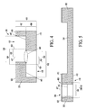
- FIG. 4 is a cross-sectional view of a lead of the leadframe of FIG. 3 along line 4-4;
- FIG. 5 is a cross-sectional view of a lead of the leadframe of FIG. 3 along line 5-5;
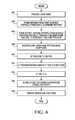
- FIG. 6 illustrates a flowchart of a method of manufacturing a leadframe and an air-cavity package for an electronic device, in accordance with various embodiments.
- FIGs. 7-11 illustrate several stages in the manufacturing process of FIG. 6 , in accordance with various embodiments.
- a “vertical” surface, axis, feature or dimension may be interpreted as a surface, axis, feature or dimension that is approximately perpendicular (e.g., +/- 10 degrees) to a “horizontal" surface, axis, feature or dimension, and vice versa. It is to be understood that the use of the terms is not meant to imply a relative orientation with respect to a fixed coordinate system (e.g., an Earth-based coordinate system).
- Embodiments include leadframes and devices with vent holes through one or more leadframe features (e.g., leads and/or the die pad).
- the vent holes are configured in a manner that reduces the likelihood that debris of sufficient size to short internal conductive structures may enter the air cavity during the lid attach process.
- each vent hole may be constructed so that the minimum cross-sectional area of a vent hole (i.e., a portion of the vent hole between the top and bottom surfaces of the leadframe feature that has the smallest opening area) is significantly narrower than the cross-sectional area of the vent hole at the top or bottom surfaces of the leadframe feature.
- each vent hole includes a constriction (or constricted portion) in the vent hole between the top and bottom surfaces of the leadframe feature.
- FIG. 1 is a top view of a leadframe 100 with a vent hole 136 formed through a lead 122, where the vent hole 136 has a substantially constant, cross-sectional opening area.
- FIG. 1 also depicts an enlarged view of a particular lead 122 of leadframe 100, so that certain features of the lead 122 are more easily visible.
- FIG. 1 illustrates only a single "cell" of a leadframe, it is to be understood that a leadframe may include multiple cells (i.e., multiple iterations of leadframe 100), which are connected together with sacrificial features. Such a configuration facilitates parallel manufacturing of multiple electronic devices (e.g., one electronic device for each leadframe cell).
- the devices may be separated from each other by removing the sacrificial features connecting the leadframe cells (i.e., the devices are singulated).
- FIG. 1 illustrates only one cell of a leadframe without any sacrificial features, and the single cell is referred to as leadframe 100.
- Leadframe 100 includes a substantially planar, conductive die pad 110 and a plurality of conductive leads 120, 121, 122 located around a perimeter of the die pad 110.
- Leads 120-122 may be substantially co-planar with the die pad, although some or all of the leads 120-122 may not be co-planar and/or may be bent, as well.
- Leads 120, 122 are spatially separated from die pad 110, so that the leads 120, 122 may be electrically isolated from the die pad 110 during later manufacturing steps, if desired.
- lead 121 is integrally formed with die pad 110. Accordingly, when it is desired to use die pad 110 as a ground plane for a subsequently manufactured device, lead 121 may be used to electrically connect with the ground plane.
- Leads 120-122 may have an elongated shape, as shown in FIG. 1 , where an inner end of each lead 120-122 is oriented toward die pad 110, and an outer end of each lead 120-122 is oriented away from die pad 110.
- lead 122 includes an inner portion 130 at the inner end, an outer portion 132 at the outer end, and an intermediate portion 134 extending between them.
- the thickness of the intermediate portion 134 may be less than the thickness of the inner and outer portions 130, 132 to accommodate molding compound above the intermediate portion 134.
- the recession defined by intermediate portion 134 may provide a mold lock feature and space for electrical insulation between the intermediate portion 134 of the lead 122 and a lid (perimeter indicated by dashed line 140), once the lid is attached.
- the intermediate portion 134 may not be thinner than the inner and/or outer portions 130, 132.
- the lid may be attached above the intermediate portion 134. After lid attach, the top surface of the inner portion 130 may be exposed within the air cavity defined by the die pad, molding compound, and lid. The bottom surfaces of inner, intermediate, and outer portions 130, 132, 134 may be exposed to the exterior environment.
- FIG. 2 which is a cross-sectional view of a lead 122 of the leadframe 100 of FIG. 1 along line 2-2, a vent hole 136 extends through the inner portion 130 of lead 122.
- the location of the vent hole 136 is within the perimeter of the lid (indicated by dashed box 140), so that the vent hole 136 may allow for pressure regulation (e.g., airflow) between the air cavity and the exterior environment during the lid attach and subsequent cure process.
- pressure regulation e.g., airflow
- Vent hole 136 extends between the top and bottom surfaces 210, 212 of lead 122. Vent hole 136 may be formed, for example, using a stamping, drilling, or etching process (e.g., an isotropic etching process). When an isotropic etching process is used to form vent hole 136, the diameter 222 of the vent hole 136 may be related to the thickness 250 of the lead 122 and the method of performing the etch. More particularly, an isotropic etching process typically removes material at approximately a same rate in all directions. Accordingly, the diameter of an opening formed using an isotropic etch may approximately equal twice the depth of the etch (assuming the opening is not etched all the way through the material).
- vent hole 136 It is desirable to maximize the depth to diameter ratio of vent hole 136, so that relatively large debris cannot enter the air cavity during lid attach and subsequent processes (i.e., debris having dimensions larger than the diameter 222 of the vent hole 136).
- vent hole 136 may be formed by isotropically etching lead 122 from both the top and bottom surfaces 210, 212.
- a first opening 220 may be etched extending from the top surface 210 toward the bottom surface 212 to a first depth 252 that is less than the thickness 250 of the lead 122
- a second opening 230 may be etched extending from the bottom surface 212 toward the top surface 210 to a second depth 254 that is less than the thickness 250 of the lead 122, but that is large enough for the second opening 230 to intersect the first opening 220.
- the vertical central axes 228 i.e., axes that are approximately perpendicular to the top and bottom surfaces 210, 212) of the openings 220, 230 are substantially aligned and co-linear, so that the cross-sectional area of vent hole 136 is substantially constant between the top and bottom surfaces 210, 212.
- a relatively narrow, radial lip may extend into the vent hole 136 at the intersection of the first and second openings 220, 230, but such a feature is not considered to result in a substantially different, cross-sectional area within the vent hole 136.
- the vertical central axes (e.g., axes 228) of two openings may be considered to be “aligned” when the axes are separated by a horizontal distance between 0% and 10% of the diameter of the openings.
- the vertical central axes (e.g., axes 228) of two openings may be considered to be “aligned” when the axes are separated by a horizontal distance between 0% and 25% of the diameter of the openings.
- a horizontal offset between the vertical central axes of up to 10% or up to 25% of the diameter of the openings may occur due to unintentional registration inaccuracies.
- the cross-sectional area of a vent hole may be considered to be "substantially constant” if no two cross-sectional areas along the length of the vent hole differ by more than 10%.
- the cross-sectional area of a vent hole e.g., vent hole 136) may be considered to be “substantially constant” if no two cross-sectional areas along the length of the vent hole differ by more than 25%.
- a "minimum cross-sectional area” refers to the smallest cross-sectional area along the length of a vent hole.
- a leadframe includes an "offset vent hole," which includes a constriction in the vent hole between the top and bottom surfaces of a leadframe feature, where the constriction defines the minimum cross-sectional area of the offset vent hole.
- the minimum cross-sectional area of the offset vent hole is significantly smaller than the minimum cross-sectional area of a vent hole (e.g., vent hole 136) formed using intersecting openings with aligned, vertical central axes.
- FIG. 3 is a top view of a leadframe 300 with an offset vent hole 336 formed through a lead 322, in accordance with an example embodiment.
- FIG. 3 should be viewed in conjunction with FIGs 4 and 5 , where FIG. 4 is a cross-sectional view of a lead of the leadframe of FIG. 3 along line 4-4, and FIG. 5 is a cross-sectional view of a lead of the leadframe of FIG. 3 along line 5-5.
- FIG. 3 also depicts an enlarged view of a particular lead 322 of leadframe 300, so that certain features of the lead 322 are more easily visible.
- FIG. 1 although FIG.
- a leadframe may include multiple cells (i.e., multiple iterations of leadframe 300), which are connected together with sacrificial features that may be subsequently removed during the process of singulating leadframe cells, packages, or devices.
- offset vent hole 336 of leadframe 300 differs from the vent hole 136 ( FIG. 1 ) of leadframe 100 in that offset vent hole 336 does not have a substantially constant cross-sectional area along the length of offset vent hole 336.
- offset vent hole 336 includes a constriction (e.g., constricted portion 460) between the top and bottom surfaces 410, 412 of the lead 322.
- the vertical central axes 429, 429 of opposed openings 420, 430 FIG.
- offset vent hole 336 used to form offset vent hole 336 are intentionally offset and mis-aligned in order to reduce the cross-sectional area of offset vent hole 336 at the constricted portion 460, where the minimum cross-sectional area of the offset vent hole 336 occurs. Accordingly, offset vent hole 336 does not have a substantially constant cross-sectional area along the length of offset vent hole 336.
- leadframe 300 includes a substantially planar, conductive die pad 310 and a plurality of conductive leads 320, 321, 322 located around a perimeter of the die pad 310.
- Leads 320-322 may be substantially co-planar with the die pad, although some or all of the leads 320-322 may not be co-planar and/or may be bent, as well.
- Leads 320, 322 are spatially separated from die pad 310, so that the leads 320, 322 may be electrically isolated from the die pad 310 during later manufacturing steps, if desired.
- lead 321 is integrally formed with die pad 310.
- die pad 310 and leads 320-322 have thicknesses (i.e., the dimension between the top and bottom surfaces) in a range of about 100 micrometers ( ⁇ m) to about 300 ⁇ m (e.g., about 200 ⁇ m), although die pad 310 and/or leads 320-322 may be thicker or thinner, as well.
- Leads 320-322 may have an elongated shape, in an embodiment, where an inner end of each lead 320-322 is oriented toward die pad 310, and an outer end of each lead 320-322 is oriented away from die pad 310.
- lead 322 includes an inner portion 330 at the inner end, an outer portion 332 at the outer end, and an intermediate portion 334 extending between them.
- the inner portion 330 of lead 322 has a width 333 in a range of about 200 ⁇ m to about 400 ⁇ m (e.g., about 300 ⁇ m), and has a length 335 in a range of about 200 ⁇ m to about 400 ⁇ m (e.g., about 300 ⁇ m), although the width 333 and/or length 335 may be larger or smaller, as well.
- the thickness of the intermediate portion 334 may be less than the thickness of the inner and outer portions 330, 332 to accommodate molding compound above the intermediate portion 334.
- the recession defined by intermediate portion 334 may provide a mold lock feature and space for electrical insulation between the intermediate portion 334 of the lead 322 and a lid (perimeter indicated by dashed line 340), once the lid is attached.
- the intermediate portion 334 may not be thinner than the inner and/or outer portions 330, 332.
- the lid may be attached above the intermediate portion 334.
- the top surface of the inner portion 330 may be exposed within the air cavity defined by the die pad 310, molding compound, and lid.
- the bottom surfaces of inner, intermediate, and outer portions 330, 332, 334 may be exposed to the exterior environment.
- the shape(s) of leads 320-322 may be different from that illustrated and described above.
- An offset vent hole 336 is formed in the inner portion 330 of one or more leads 322 or other leadframe features (e.g., die pad 310), in an embodiment.
- offset vent holes 336 are shown in two leads 322 in FIG. 3 , it is to be understood that offset vent holes 336 may be formed in more than two leads 320-322 and/or in as few as a single lead 322.
- an offset vent hole also or alternatively may be formed in die pad 310. Accordingly, the description herein may refer to formation of a vent hole in a "leadframe feature" (i.e., a conductive feature of a leadframe, including a die pad or a lead).
- each offset vent hole 336 is located within the perimeter of the lid (indicated by dashed box 340), so that each offset vent hole 336 is positioned to allow for pressure regulation (e.g., airflow) between the air cavity and the exterior environment during the lid attach process.
- pressure regulation e.g., airflow
- offset vent hole 336 extends between the top and bottom surfaces 410, 412 of lead 322.
- Offset vent hole 336 may be formed, for example, using a drilling or etching process (e.g., an isotropic etching process). According to an embodiment in which offset vent hole 336 is formed using an isotropic etching process, the depth to diameter ratio of offset vent hole 336 is maximized by etching lead 322 from both the top and bottom surfaces 410, 412.
- a first opening 420 may be etched extending from the top surface 410 toward the bottom surface 412 to a first depth 452 that is less than the thickness 450 of the lead 322, and a second opening 430 may be etched extending from the bottom surface 412 toward the top surface 410 to a second depth 454 that is less than the thickness 450 of the lead 322, but that is large enough for the second opening 430 to intersect the first opening 420.
- the first and second depths 452, 454 are approximately equal (e.g., approximately 50% of the thickness 450 of the lead 322), although they may be unequal, as well.
- the cross-sectional areas 338, 432 of openings 420, 430 are approximately equal at surfaces 410, 412, respectively. In other embodiments, the cross-sectional areas 338, 432 at surfaces 410, 412 may not be equal.
- the vertical central axes 428, 429 of the openings 420, 430 formed to produce offset vent hole 336 are intentionally horizontally offset or mis-aligned (i.e., intentionally mis-registered so that they are not aligned or co-linear), so that the cross-sectional area of offset vent hole 336 varies substantially between the top and bottom surfaces 410, 412.
- a substantial offset between the vertical central axes 428, 429 results in a constricted portion 460 of offset vent hole 336 at the intersection of the first and second openings 420, 430.
- the vertical central axis 427 of offset vent hole 336 may be considered to be halfway between the vertical central axes 428, 429 of first and second openings 420, 430. Accordingly, each of the vertical central axes 428, 429 of first and second openings 420 are offset from the vertical central axis 427 of offset vent hole 336 by substantially equal offset distances 426, 436, respectively. In an embodiment, the vertical central axes 428, 429 are offset from each other by a horizontal offset distance 424 in a range between about 10% and about 90% of the diameter 338, 432 of the openings at a top or bottom surfaces 410, 412 of the lead 322 (or the diameter of the smaller opening, if they are not equal in diameter).
- the vertical central axes 428, 429 are offset from each other by a horizontal offset distance 424 in a range between about 25% and about 75% of the diameter 338, 432 of the openings at a top or bottom surfaces 410, 412 of the lead 322 (or the diameter of the smaller opening, if they are not equal in diameter).
- the vertical central axes 428, 429 are offset from each other by a horizontal offset distance 424 in a range between about 50% and about 90% of the diameter 338, 432 of the openings at a top or bottom surfaces 410, 412 of the lead 322 (or the diameter of the smaller opening, if they are not equal in diameter).
- the cross-sectional area of offset vent hole 336 varies substantially along its length.
- the cross-sectional area of offset vent hole 336 at either surface 410, 412 is a function of the diameters 338, 432 of the openings 420, 430 at the surfaces 410, 412.
- the cross sectional area of the offset vent hole 336 at the constricted portion 460 is a function of the degree that openings 420, 430 intersect at the constricted portion 460.
- the "eye-shaped" cross-sectional area at the constricted portion 460 is a function of the major and minor dimensions 350, 360 of the opening at the constricted portion 460.
- the major and minor dimensions of the cross sectional area would be 200 ⁇ m along the entire length of the vent hole.
- both the major and minor dimensions 350, 360 at the constricted portion 460 decrease.
- the major dimension 350 would reduce to about 193.6 ⁇ m, and the minor dimension 360 would reduce to about 150 ⁇ m.
- the major dimension 350 would reduce to about 132.3 ⁇ m, and the minor dimension 360 would reduce to about 50 ⁇ m.
- the cross-sectional area of a vent hole may be considered to "vary substantially” (i.e., not to be “substantially constant") if any two cross-sectional areas along the vertical length of the vent hole differ by more than 10% (e.g., differ by about 10% to about 90%).
- the cross-sectional area of a vent hole e.g., offset vent hole 336) may be considered to "vary substantially” if any two cross-sectional areas along the vertical length of the vent hole differ by more than 25% (e.g., differ by about 25% to about 90%).
- the cross-sectional area of a vent hole may be considered to "vary substantially” if any two cross-sectional areas along the vertical length of the vent hole differ by more than 50% (e.g., differ by about 50% to about 90%).
- the cross-sectional area of a vent hole e.g., offset vent hole 336) may be considered to "vary substantially” if any two cross-sectional areas along the vertical length of the vent hole differ by more than 75% (e.g., differ by about 75% to about 90%).
- each of the openings 420, 430 are partially defined by bottom surfaces 440, 442 (e.g., shelves within the interior of the offset vent hole 336.
- the implementation of offset vertical central axes 428, 429 results in the constricted portion 460 of offset vent hole 336.
- a vent hole is considered to include a "constriction” or “constricted portion” (e.g., constricted portion 460) when the vent hole includes a portion at which the maximum and minimum cross-sectional areas of the vent hole differ by more than 10% (e.g., differ by about 10% to about 90%), where the "constriction” or “constricted portion” occurs at the location along the vent hole with the minimum cross-sectional area.
- a "constriction” or “constricted portion” e.g., constricted portion 460
- a vent hole is considered to include a "constriction” or “constricted portion” (e.g., constricted portion 460) when the vent hole includes a portion at which the maximum and minimum cross-sectional areas of the vent hole differ by more than 25% (e.g., differ by about 25% to about 90%).
- a vent hole is considered to include a "constriction” or “constricted portion” (e.g., constricted portion 460) when the vent hole includes a portion at which the maximum and minimum cross-sectional areas of the vent hole differ by more than 50% (e.g., differ by about 50% to about 90%).
- a vent hole is considered to include a "constriction” or “constricted portion” (e.g., constricted portion 460) when the vent hole includes a portion at which the maximum and minimum cross-sectional areas of the vent hole differ by more than 75% (e.g., differ by about 75% to about 90%).
- offsetting the vertical central axes 428, 429 of openings 420, 430 allows an offset vent hole 336 to be formed, which has a minimum cross-sectional area that is significantly less than the cross-sectional area of a vent hole formed from aligned openings (e.g., vent hole 136), given same diameter openings. Accordingly, implementation of the various embodiments may restrict relatively large debris from entering an air cavity during a lid attach process, where such debris may enter an air cavity when aligned openings are implemented. Accordingly, implementation of the various embodiments may result in a substantial benefit in terms of manufacturing yield and device reliability.
- FIG. 6 illustrates a flowchart of a method of manufacturing a leadframe and an air-cavity package for an electronic device, in accordance with various embodiments.
- FIG. 6 should be viewed in conjunction with FIGs. 7-11 , which illustrate several stages in the manufacturing process.
- the below-described and illustrated leadframes and air-cavity packages correspond to QFN (Quad-Flat-No leads) packages.
- QFN Quad-Flat-No leads
- DFN Dual-Flat-No leads
- the various embodiments may be implemented in other types of packages, as well, including DFN (Dual-Flat-No leads) packages, and other packages in which the top and bottom surfaces of a leadframe feature are not encapsulated in a molding compound.
- the leadframes illustrated and described herein include a conductive die pad, other embodiments may include leadframes or packages without conductive die pads.
- the method may begin, in block 602, by providing a leadframe (e.g., leadframe 300 prior to formation of offset vent holes 336, FIG. 3 ).
- the leadframe may be formed from copper, a copper alloy, or another rigid conductive material.
- the leadframe may include a die pad (e.g., die pad 710, FIG. 7 ) and a plurality of leads surrounding the die pad, where the die pad and the leads are held in a fixed, spatial orientation by sacrificial features.
- the leads may include first leads 720 that will not include vent holes, second leads 721 integrally formed with the die pad 710, and third leads 722 that will include vent holes.
- one or more vent holes 736 are formed in one or more leadframe features by forming first and second openings (e.g., openings 320, 330, FIG. 3 ) partially through the leadframe feature(s).
- first and second openings extend from first and second surfaces (e.g., surfaces 410, 412, FIG. 4 ), respectively, of the leadframe feature(s).
- the first and second openings may be formed through one or more leads (e.g., leads 722, FIG. 7 ) and/or the die pad (e.g., die pad 710, FIG. 7 ).
- the vertical central axes (e.g., axes 428, 429, FIG. 4 ) of the openings are intentionally offset a horizontal distance, so that the resulting vent hole (e.g., vent hole 736, FIG. 7 ) includes a constricted portion (e.g., constricted portion 460, FIG. 4 ) with a relatively small, minimum cross-sectional area.
- vent holes After formation of the vent holes, at least those portions of the leadframe that include the vent holes may be plated with other conductive materials (e.g., gold) and/or a solder plating material (e.g., nickel palladium gold (NiPdAu) solder plating, or some other material) to ensure that the vent holes are solder wettable (e.g., so that the vent holes may later be filled with solder material).
- conductive materials e.g., gold
- a solder plating material e.g., nickel palladium gold (NiPdAu) solder plating, or some other material
- one or more offset vent holes are formed in a leadframe after the leadframe has been fabricated.
- the one or more offset vent holes may be formed in a leadframe simultaneously with fabrication of the leadframe itself.
- the leadframe and the vent hole(s) may be formed sequentially or simultaneously.
- the one or more offset venting holes may be formed simultaneously with forming a leadframe's leads and die pad (e.g., using the same etching steps).
- a package base 700 (with top and bottom surfaces 702, 704) is formed by partially encapsulating the die pad 710 and leads 720, 721, 722 with molding compound 730 (e.g., a thermoplastic material, an epoxy resin molding compound, or other materials).
- molding compound 730 e.g., a thermoplastic material, an epoxy resin molding compound, or other materials.
- the offset vent holes 736 may be protected (e.g., temporarily covered or filled or clamped against a mold tool) so that molding compound does not obstruct or seal the vent holes 736.
- the mold compound is dispensed so that portions of the top surfaces of die pad 710 and leads 720-722 ultimately will be exposed within an air cavity of the package, and the bottom surfaces of die pad 710 and leads 720-722 ultimately will be exposed to the exterior environment at a bottom surface 704 of the package base 700.
- the outward ends of leads 720-722 also may be exposed to the exterior environment, as illustrated.
- one or more die 902, 903 may be attached to the die pad 710, and one or more additional die 904, 905, 906 or other components may be stacked above them.
- wirebonds and/or other electrical connections are coupled between some or all of the die 902-906 and the leads (e.g., leads 720, 722).
- a lid attach process is performed, in order to attach a lid 1002 to the top surface 702 of the package base 700.
- an air cavity within the package is defined by the top surface of the package base 700 and the interior surface of the lid 1002.
- the offset vent hole(s) 736 allow air to flow between the air cavity and the exterior environment.
- the lid 1002 may be a dome shaped lid (as shown in FIG. 10 ).
- the package base may be configured to accept a flat lid.
- lid 1002 may be formed from an organic plastic, liquid crystal polymer, aluminum, ceramic, glass, steel, and so on.
- a heat-curable adhesive or epoxy may be applied to the mating surface(s) of the lid 1002 and/or the package base 700, and the assembly is cured at an elevated temperature (e.g., between about 150°C to 175°C (300°F to 350°F)) for a cure period (e.g., about an hour).
- the package base 700 and lid 1010 may be attached using solder or another material.
- the offset vent holes 736 allow for pressure normalization between the air cavity and the external environment.
- the offset vent hole(s) 736 may be closed, in block 616, although they may remain open, in other embodiments.
- FIG. 11 which is a cross-sectional view of a closed, offset vent hole 1136 (e.g., offset vent hole 336 or 736) through a leadframe feature 1100 (e.g., through lead 322 as in the cross-section of FIG. 4 ).
- solder 1140 may be deposited in the offset vent hole 1136 (e.g., during a solder reflow process) in order to close the offset vent hole 1136.
- a fill material other than solder may be used to close the offset vent hole(s). Closure of the offset vent hole(s) results in a hermetic or semi-hermetic seal between the air cavity and the external environment.
- the sacrificial features of the leadframe may be removed.
- removal of the sacrificial features may result in singulation of the packaged electronic devices.
- the sacrificial features of the leadframe may be removed at an earlier point in the manufacturing process. In any event, completion of the manufacturing process yields an electronic device packaged in an air cavity package, which includes one or more offset vent holes in one or more leadframe features.
- An embodiment of a device includes a leadframe feature having a first surface, a second surface opposed to the first surface, and a vent hole formed between the first surface and the second surface.
- a cross-sectional area of the vent hole varies substantially between the first surface and the second surface.
- the vent hole has a constricted portion between the first surface and the second surface, where a first cross-sectional area of the vent hole at the constricted portion is in a range from 10 to 90 percent of a second cross-sectional area at the first surface.
- the vent hole includes a first opening extending from the first surface toward the second surface to a first depth that is less than a thickness of the leadframe feature, and a second opening extending from the second surface toward the first surface to a second depth that is less than the thickness of the leadframe feature, but that is large enough for the second opening to intersect the first opening.
- a vertical central axis of the first opening and a vertical central axis of the second opening are horizontally offset from each other by a distance in a range from 10 to 90 percent of a diameter of the first opening, and a constricted portion of the vent hole corresponds to an intersection of the first opening and the second opening.
- the vertical central axis of the first opening and the vertical central axis of the second opening are horizontally offset from each other by a distance in a range from 25 to 75 percent of the diameter of the first opening. In yet another embodiment, the vertical central axis of the first opening and the vertical central axis of the second opening are horizontally offset from each other by a distance in a range from 50 to 90 percent of the diameter of the first opening.
- An embodiment of a leadframe includes a leadframe feature having a first surface, a second surface opposed to the first surface, and a vent hole formed between the first surface and the second surface.
- a cross-sectional area of the vent hole varies substantially between the first surface and the second surface.
- the vent hole includes a first opening extending from the first surface toward the second surface to a first depth that is less than a thickness of the leadframe feature, and a second opening extending from the second surface toward the first surface to a second depth that is less than the thickness of the leadframe feature, but that is large enough for the second opening to intersect the first opening.
- a vertical central axis of the first opening and a vertical central axis of the second opening are horizontally offset from each other by a distance in a range from 10 to 90 percent of a diameter of the first opening, and a constricted portion of the vent hole corresponds to an intersection of the first opening and the second opening.
- the vertical central axis of the first opening and the vertical central axis of the second opening are horizontally offset from each other by a distance in a range from 25 to 75 percent of the diameter of the first opening.
- An embodiment of a method includes forming a leadframe that includes a leadframe feature having a first surface and a second surface opposed to the first surface, and forming a vent hole between the first surface and the second surface of the leadframe feature.
- the vent hole is formed so that a cross-sectional area of the vent hole varies substantially between the first surface and the second surface.
- forming the vent hole includes forming a first opening extending from the first surface toward the second surface to a first depth that is less than a thickness of the leadframe feature, and forming a second opening extending from the second surface toward the first surface to a second depth that is less than the thickness of the leadframe feature, but that is large enough for the second opening to intersect the first opening, where a vertical central axis of the first opening and a vertical central axis of the second opening are horizontally offset from each other by a distance in a range from 10 to 90 percent of a diameter of the first opening, and a constricted portion of the vent hole corresponds to an intersection of the first opening and the second opening.
Landscapes
- Lead Frames For Integrated Circuits (AREA)
- Led Device Packages (AREA)
Abstract
Description
- Embodiments of the subject matter described herein relate generally to electronic devices with air-cavity packages, leadframes for such devices, and methods of their manufacture.
- Electronic device air-cavity packages include a base and a lid, which together define an enclosed interior cavity within which various types of electronic die may be attached. In some types of packages, the base comprises a die pad (or "flag") surrounded by a plurality of leads, where the combination is structurally supported by molding compound. Typically, manufacturing the base involves providing a leadframe (i.e., a conductive structure that includes one or more instances of the die pad/lead combination, held in spatial orientation by sacrificial features), placing the leadframe in a mold, and surrounding side surfaces of the die pad and leads with the molding compound so that top and bottom surfaces of the die pad and leads are exposed.
- During the device assembly process, one or more dies are attached to the die pad, electrical connections are established between the die and the leads (e.g., using wirebonds and/or other conductive features), and the lid is attached to the base. When a lid is to be permanently attached to the base, a heat-curably epoxy is typically applied to the mating surface of the lid and/or base, and the assembly is cured at an elevated temperature (e.g., between about 150°C to 175°C) for a cure period (e.g., about an hour). To allow for pressure normalization between the air cavity and the external environment during the lid cure process, one or more vent holes are typically provided in the assembly prior to the process. The holes may be later sealed to hermetically or semi-hermetically seal the air cavity, although the holes may be left open, in some packages.
- Although provision of vent holes reduces the likelihood that the seal between the base and the lid may rupture during the lid attach process (e.g., due to differential pressures between the air cavity and outside environment), the use of such holes is not without its issues. For example, debris from the outside environment may enter the air cavity through the vent holes when they are unsealed, and this debris could short exposed wirebonds or other conductive features within the air cavity. Accordingly, although the use of vent holes alleviates some manufacturing issues, the vent holes cause other issues.
- A more complete understanding of the subject matter may be derived by referring to the detailed description and claims when considered in conjunction with the following figures, wherein like reference numbers refer to similar elements throughout the figures.
-
FIG. 1 is a top view of a leadframe with a vent hole formed through a lead; -
FIG. 2 is a cross-sectional view of a lead of the leadframe ofFIG. 1 along line 2-2; -
FIG. 3 a top view of a leadframe with an offset vent hole formed through a lead, in accordance with an example embodiment; -
FIG. 4 is a cross-sectional view of a lead of the leadframe ofFIG. 3 along line 4-4; -
FIG. 5 is a cross-sectional view of a lead of the leadframe ofFIG. 3 along line 5-5; -
FIG. 6 illustrates a flowchart of a method of manufacturing a leadframe and an air-cavity package for an electronic device, in accordance with various embodiments; and -
FIGs. 7-11 illustrate several stages in the manufacturing process ofFIG. 6 , in accordance with various embodiments. - The following detailed description is merely illustrative in nature and is not intended to limit the embodiments of the subject matter or the application and uses of such embodiments. As used herein, the word "exemplary" means "serving as an example, instance, or illustration." Any implementation described herein as exemplary is not necessarily to be construed as preferred or advantageous over other implementations. Furthermore, there is no intention to be bound by any expressed or implied theory presented in the preceding technical field, background, or the following detailed description.
- For the purpose of indicating the relative orientation of various surfaces, axes, and other features or dimensions with respect to each other, the terms "vertical" and "horizontal" may be used herein. More specifically, a "vertical" surface, axis, feature or dimension may be interpreted as a surface, axis, feature or dimension that is approximately perpendicular (e.g., +/- 10 degrees) to a "horizontal" surface, axis, feature or dimension, and vice versa. It is to be understood that the use of the terms is not meant to imply a relative orientation with respect to a fixed coordinate system (e.g., an Earth-based coordinate system).
- Embodiments include leadframes and devices with vent holes through one or more leadframe features (e.g., leads and/or the die pad). As will be explained in more detail below, the vent holes are configured in a manner that reduces the likelihood that debris of sufficient size to short internal conductive structures may enter the air cavity during the lid attach process. For example, each vent hole may be constructed so that the minimum cross-sectional area of a vent hole (i.e., a portion of the vent hole between the top and bottom surfaces of the leadframe feature that has the smallest opening area) is significantly narrower than the cross-sectional area of the vent hole at the top or bottom surfaces of the leadframe feature. In other words, according to various embodiments, each vent hole includes a constriction (or constricted portion) in the vent hole between the top and bottom surfaces of the leadframe feature.
- For purposes of comparison,
FIG. 1 is a top view of aleadframe 100 with avent hole 136 formed through alead 122, where thevent hole 136 has a substantially constant, cross-sectional opening area.FIG. 1 also depicts an enlarged view of aparticular lead 122 ofleadframe 100, so that certain features of thelead 122 are more easily visible. AlthoughFIG. 1 illustrates only a single "cell" of a leadframe, it is to be understood that a leadframe may include multiple cells (i.e., multiple iterations of leadframe 100), which are connected together with sacrificial features. Such a configuration facilitates parallel manufacturing of multiple electronic devices (e.g., one electronic device for each leadframe cell). After performing some or all processes associated with manufacturing electronic devices using the leadframe cells, the devices may be separated from each other by removing the sacrificial features connecting the leadframe cells (i.e., the devices are singulated). For purposes of simplicity,FIG. 1 illustrates only one cell of a leadframe without any sacrificial features, and the single cell is referred to asleadframe 100. -
Leadframe 100 includes a substantially planar,conductive die pad 110 and a plurality ofconductive leads die pad 110. Leads 120-122 may be substantially co-planar with the die pad, although some or all of the leads 120-122 may not be co-planar and/or may be bent, as well.Leads pad 110, so that theleads die pad 110 during later manufacturing steps, if desired. In contrast,lead 121 is integrally formed with diepad 110. Accordingly, when it is desired to use diepad 110 as a ground plane for a subsequently manufactured device,lead 121 may be used to electrically connect with the ground plane. - Leads 120-122 may have an elongated shape, as shown in
FIG. 1 , where an inner end of each lead 120-122 is oriented toward diepad 110, and an outer end of each lead 120-122 is oriented away from diepad 110. For example,lead 122 includes aninner portion 130 at the inner end, anouter portion 132 at the outer end, and anintermediate portion 134 extending between them. The thickness of theintermediate portion 134 may be less than the thickness of the inner andouter portions intermediate portion 134. The recession defined byintermediate portion 134 may provide a mold lock feature and space for electrical insulation between theintermediate portion 134 of thelead 122 and a lid (perimeter indicated by dashed line 140), once the lid is attached. Alternatively, theintermediate portion 134 may not be thinner than the inner and/orouter portions die pad 110 and leads, the lid may be attached above theintermediate portion 134. After lid attach, the top surface of theinner portion 130 may be exposed within the air cavity defined by the die pad, molding compound, and lid. The bottom surfaces of inner, intermediate, andouter portions - Referring also to
FIG. 2 , which is a cross-sectional view of alead 122 of theleadframe 100 ofFIG. 1 along line 2-2, avent hole 136 extends through theinner portion 130 oflead 122. The location of thevent hole 136 is within the perimeter of the lid (indicated by dashed box 140), so that thevent hole 136 may allow for pressure regulation (e.g., airflow) between the air cavity and the exterior environment during the lid attach and subsequent cure process. -
Vent hole 136 extends between the top andbottom surfaces lead 122.Vent hole 136 may be formed, for example, using a stamping, drilling, or etching process (e.g., an isotropic etching process). When an isotropic etching process is used to formvent hole 136, thediameter 222 of thevent hole 136 may be related to thethickness 250 of thelead 122 and the method of performing the etch. More particularly, an isotropic etching process typically removes material at approximately a same rate in all directions. Accordingly, the diameter of an opening formed using an isotropic etch may approximately equal twice the depth of the etch (assuming the opening is not etched all the way through the material). It is desirable to maximize the depth to diameter ratio ofvent hole 136, so that relatively large debris cannot enter the air cavity during lid attach and subsequent processes (i.e., debris having dimensions larger than thediameter 222 of the vent hole 136). To maximize the depth to diameter ratio,vent hole 136 may be formed by isotropically etchinglead 122 from both the top andbottom surfaces vent hole 136, afirst opening 220 may be etched extending from thetop surface 210 toward thebottom surface 212 to afirst depth 252 that is less than thethickness 250 of thelead 122, and asecond opening 230 may be etched extending from thebottom surface 212 toward thetop surface 210 to asecond depth 254 that is less than thethickness 250 of thelead 122, but that is large enough for thesecond opening 230 to intersect thefirst opening 220. The vertical central axes 228 (i.e., axes that are approximately perpendicular to the top andbottom surfaces 210, 212) of theopenings vent hole 136 is substantially constant between the top andbottom surfaces vent hole 136 at the intersection of the first andsecond openings vent hole 136. - As used herein, the vertical central axes (e.g., axes 228) of two openings may be considered to be "aligned" when the axes are separated by a horizontal distance between 0% and 10% of the diameter of the openings. Alternatively, the vertical central axes (e.g., axes 228) of two openings may be considered to be "aligned" when the axes are separated by a horizontal distance between 0% and 25% of the diameter of the openings. For example, a horizontal offset between the vertical central axes of up to 10% or up to 25% of the diameter of the openings may occur due to unintentional registration inaccuracies. As used herein, the cross-sectional area of a vent hole (e.g., vent hole 136) may be considered to be "substantially constant" if no two cross-sectional areas along the length of the vent hole differ by more than 10%. Alternatively, the cross-sectional area of a vent hole (e.g., vent hole 136) may be considered to be "substantially constant" if no two cross-sectional areas along the length of the vent hole differ by more than 25%. As used herein, a "minimum cross-sectional area" refers to the smallest cross-sectional area along the length of a vent hole.
- As indicated previously, debris may enter an air cavity through
vent hole 136 during and after the lid attach process. The size of the debris that may enter the air cavity through thevent hole 136 is limited by the minimum cross-sectional area along the length of thevent hole 136. Accordingly, ifvent hole 136 has a relatively large, cross-sectional area, relatively large debris may enter the air cavity throughvent hole 136. Conversely, ifvent hole 136 has a relatively small cross-sectional area, only smaller debris may enter the air cavity throughvent hole 136. In various embodiments, a leadframe includes an "offset vent hole," which includes a constriction in the vent hole between the top and bottom surfaces of a leadframe feature, where the constriction defines the minimum cross-sectional area of the offset vent hole. The minimum cross-sectional area of the offset vent hole is significantly smaller than the minimum cross-sectional area of a vent hole (e.g., vent hole 136) formed using intersecting openings with aligned, vertical central axes. - For example,
FIG. 3 is a top view of aleadframe 300 with an offsetvent hole 336 formed through alead 322, in accordance with an example embodiment. For enhanced understanding,FIG. 3 should be viewed in conjunction withFIGs 4 and 5 , whereFIG. 4 is a cross-sectional view of a lead of the leadframe ofFIG. 3 along line 4-4, andFIG. 5 is a cross-sectional view of a lead of the leadframe ofFIG. 3 along line 5-5.FIG. 3 also depicts an enlarged view of aparticular lead 322 ofleadframe 300, so that certain features of thelead 322 are more easily visible. As withFIG. 1 , althoughFIG. 3 illustrates only a single "cell" of a leadframe, it is to be understood that a leadframe may include multiple cells (i.e., multiple iterations of leadframe 300), which are connected together with sacrificial features that may be subsequently removed during the process of singulating leadframe cells, packages, or devices. - As will be discussed in detail below, the offset
vent hole 336 ofleadframe 300 differs from the vent hole 136 (FIG. 1 ) ofleadframe 100 in that offsetvent hole 336 does not have a substantially constant cross-sectional area along the length of offsetvent hole 336. Instead, according to an embodiment, offsetvent hole 336 includes a constriction (e.g., constricted portion 460) between the top andbottom surfaces lead 322. According to an embodiment, the verticalcentral axes opposed openings 420, 430 (FIG. 4 ) used to form offsetvent hole 336 are intentionally offset and mis-aligned in order to reduce the cross-sectional area of offsetvent hole 336 at theconstricted portion 460, where the minimum cross-sectional area of the offsetvent hole 336 occurs. Accordingly, offsetvent hole 336 does not have a substantially constant cross-sectional area along the length of offsetvent hole 336. - Similar to the
leadframe 100 ofFIG. 1 ,leadframe 300 includes a substantially planar,conductive die pad 310 and a plurality ofconductive leads die pad 310. Leads 320-322 may be substantially co-planar with the die pad, although some or all of the leads 320-322 may not be co-planar and/or may be bent, as well.Leads die pad 310, so that theleads die pad 310 during later manufacturing steps, if desired. In contrast, lead 321 is integrally formed withdie pad 310. Accordingly, when it is desired to usedie pad 310 as a ground plane for a subsequently manufactured device, lead 321 may be used to electrically connect with the ground plane. According to an embodiment, diepad 310 and leads 320-322 have thicknesses (i.e., the dimension between the top and bottom surfaces) in a range of about 100 micrometers (µm) to about 300 µm (e.g., about 200 µm), although diepad 310 and/or leads 320-322 may be thicker or thinner, as well. - Leads 320-322 may have an elongated shape, in an embodiment, where an inner end of each lead 320-322 is oriented toward
die pad 310, and an outer end of each lead 320-322 is oriented away fromdie pad 310. For example, lead 322 includes aninner portion 330 at the inner end, anouter portion 332 at the outer end, and anintermediate portion 334 extending between them. According to an embodiment, theinner portion 330 oflead 322 has awidth 333 in a range of about 200 µm to about 400 µm (e.g., about 300 µm), and has alength 335 in a range of about 200 µm to about 400 µm (e.g., about 300 µm), although thewidth 333 and/orlength 335 may be larger or smaller, as well. The thickness of theintermediate portion 334 may be less than the thickness of the inner andouter portions intermediate portion 334. The recession defined byintermediate portion 334 may provide a mold lock feature and space for electrical insulation between theintermediate portion 334 of thelead 322 and a lid (perimeter indicated by dashed line 340), once the lid is attached. Alternatively, theintermediate portion 334 may not be thinner than the inner and/orouter portions die pad 310 and leads 320-322, the lid may be attached above theintermediate portion 334. After lid attach, the top surface of theinner portion 330 may be exposed within the air cavity defined by thedie pad 310, molding compound, and lid. The bottom surfaces of inner, intermediate, andouter portions - An offset
vent hole 336 is formed in theinner portion 330 of one or more leads 322 or other leadframe features (e.g., die pad 310), in an embodiment. Although offset vent holes 336 are shown in twoleads 322 inFIG. 3 , it is to be understood that offset vent holes 336 may be formed in more than two leads 320-322 and/or in as few as asingle lead 322. In still other alternate embodiments, an offset vent hole also or alternatively may be formed indie pad 310. Accordingly, the description herein may refer to formation of a vent hole in a "leadframe feature" (i.e., a conductive feature of a leadframe, including a die pad or a lead). Either way, each offsetvent hole 336 is located within the perimeter of the lid (indicated by dashed box 340), so that each offsetvent hole 336 is positioned to allow for pressure regulation (e.g., airflow) between the air cavity and the exterior environment during the lid attach process. - In the embodiment illustrated in
FIGs 3-5 , offsetvent hole 336 extends between the top andbottom surfaces lead 322. Offsetvent hole 336 may be formed, for example, using a drilling or etching process (e.g., an isotropic etching process). According to an embodiment in which offsetvent hole 336 is formed using an isotropic etching process, the depth to diameter ratio of offsetvent hole 336 is maximized by etchinglead 322 from both the top andbottom surfaces vent hole 336, afirst opening 420 may be etched extending from thetop surface 410 toward thebottom surface 412 to afirst depth 452 that is less than thethickness 450 of thelead 322, and asecond opening 430 may be etched extending from thebottom surface 412 toward thetop surface 410 to asecond depth 454 that is less than thethickness 450 of thelead 322, but that is large enough for thesecond opening 430 to intersect thefirst opening 420. According to an embodiment, the first andsecond depths thickness 450 of the lead 322), although they may be unequal, as well. In addition, according to an embodiment, thecross-sectional areas openings surfaces cross-sectional areas surfaces - In contrast with the
openings FIGs 1 ,2 ), the verticalcentral axes openings vent hole 336 are intentionally horizontally offset or mis-aligned (i.e., intentionally mis-registered so that they are not aligned or co-linear), so that the cross-sectional area of offsetvent hole 336 varies substantially between the top andbottom surfaces central axes constricted portion 460 of offsetvent hole 336 at the intersection of the first andsecond openings - The vertical
central axis 427 of offsetvent hole 336 may be considered to be halfway between the verticalcentral axes second openings central axes second openings 420 are offset from the verticalcentral axis 427 of offsetvent hole 336 by substantially equal offsetdistances central axes distance 424 in a range between about 10% and about 90% of thediameter bottom surfaces central axes distance 424 in a range between about 25% and about 75% of thediameter bottom surfaces central axes distance 424 in a range between about 50% and about 90% of thediameter bottom surfaces - Due to the offset between the vertical
central axes second openings vent hole 336 varies substantially along its length. For example, for the substantiallycylindrical openings vent hole 336 at eithersurface diameters openings surfaces vent hole 336 at theconstricted portion 460 is a function of the degree thatopenings constricted portion 460. Referring toFIG. 3 , the "eye-shaped" cross-sectional area at theconstricted portion 460 is a function of the major andminor dimensions constricted portion 460. For example, if the openings each had a 200 µm diameter and zero offset between their vertical axes (e.g.,openings FIGs 1 ,2 ), the major and minor dimensions of the cross sectional area would be 200 µm along the entire length of the vent hole. However, as the offset between the first andsecond openings minor dimensions constricted portion 460 decrease. For example, givenopenings central axes 428, 429 (e.g., an offset of 25% of the diameter of theopenings 420, 430), themajor dimension 350 would reduce to about 193.6 µm, and theminor dimension 360 would reduce to about 150 µm. As another example, givenopenings central axes 428, 429 (e.g., an offset of 75% of the diameter of theopenings 420, 430), themajor dimension 350 would reduce to about 132.3 µm, and theminor dimension 360 would reduce to about 50 µm. - As used herein, the cross-sectional area of a vent hole (e.g., offset vent hole 336) may be considered to "vary substantially" (i.e., not to be "substantially constant") if any two cross-sectional areas along the vertical length of the vent hole differ by more than 10% (e.g., differ by about 10% to about 90%). Alternatively, the cross-sectional area of a vent hole (e.g., offset vent hole 336) may be considered to "vary substantially" if any two cross-sectional areas along the vertical length of the vent hole differ by more than 25% (e.g., differ by about 25% to about 90%). Alternatively, the cross-sectional area of a vent hole (e.g., offset vent hole 336) may be considered to "vary substantially" if any two cross-sectional areas along the vertical length of the vent hole differ by more than 50% (e.g., differ by about 50% to about 90%). Alternatively, the cross-sectional area of a vent hole (e.g., offset vent hole 336) may be considered to "vary substantially" if any two cross-sectional areas along the vertical length of the vent hole differ by more than 75% (e.g., differ by about 75% to about 90%).
- Because the vertical
central axes openings openings entire thickness 450 of thelead 322, each of theopenings bottom surfaces 440, 442 (e.g., shelves within the interior of the offsetvent hole 336. In addition, the implementation of offset verticalcentral axes constricted portion 460 of offsetvent hole 336. As used herein, a vent hole is considered to include a "constriction" or "constricted portion" (e.g., constricted portion 460) when the vent hole includes a portion at which the maximum and minimum cross-sectional areas of the vent hole differ by more than 10% (e.g., differ by about 10% to about 90%), where the "constriction" or "constricted portion" occurs at the location along the vent hole with the minimum cross-sectional area. Alternatively, a vent hole is considered to include a "constriction" or "constricted portion" (e.g., constricted portion 460) when the vent hole includes a portion at which the maximum and minimum cross-sectional areas of the vent hole differ by more than 25% (e.g., differ by about 25% to about 90%). Alternatively, a vent hole is considered to include a "constriction" or "constricted portion" (e.g., constricted portion 460) when the vent hole includes a portion at which the maximum and minimum cross-sectional areas of the vent hole differ by more than 50% (e.g., differ by about 50% to about 90%). Alternatively, a vent hole is considered to include a "constriction" or "constricted portion" (e.g., constricted portion 460) when the vent hole includes a portion at which the maximum and minimum cross-sectional areas of the vent hole differ by more than 75% (e.g., differ by about 75% to about 90%). - As the Figures and the above description indicate, offsetting the vertical
central axes openings vent hole 336 to be formed, which has a minimum cross-sectional area that is significantly less than the cross-sectional area of a vent hole formed from aligned openings (e.g., vent hole 136), given same diameter openings. Accordingly, implementation of the various embodiments may restrict relatively large debris from entering an air cavity during a lid attach process, where such debris may enter an air cavity when aligned openings are implemented. Accordingly, implementation of the various embodiments may result in a substantial benefit in terms of manufacturing yield and device reliability. -
FIG. 6 illustrates a flowchart of a method of manufacturing a leadframe and an air-cavity package for an electronic device, in accordance with various embodiments.FIG. 6 should be viewed in conjunction withFIGs. 7-11 , which illustrate several stages in the manufacturing process. The below-described and illustrated leadframes and air-cavity packages correspond to QFN (Quad-Flat-No leads) packages. It should be understood that the various embodiments may be implemented in other types of packages, as well, including DFN (Dual-Flat-No leads) packages, and other packages in which the top and bottom surfaces of a leadframe feature are not encapsulated in a molding compound. In addition, although the leadframes illustrated and described herein include a conductive die pad, other embodiments may include leadframes or packages without conductive die pads. - In any event, the method may begin, in
block 602, by providing a leadframe (e.g.,leadframe 300 prior to formation of offset vent holes 336,FIG. 3 ). For example, the leadframe may be formed from copper, a copper alloy, or another rigid conductive material. The leadframe may include a die pad (e.g., diepad 710,FIG. 7 ) and a plurality of leads surrounding the die pad, where the die pad and the leads are held in a fixed, spatial orientation by sacrificial features. For example, the leads may include first leads 720 that will not include vent holes, second leads 721 integrally formed with thedie pad 710, andthird leads 722 that will include vent holes. - In blocks 604 and 606, which may be performed in parallel or sequentially, one or more vent holes 736 (e.g., offset
vent hole 336,FIG. 3 ) are formed in one or more leadframe features by forming first and second openings (e.g.,openings FIG. 3 ) partially through the leadframe feature(s). As discussed previously, the first and second openings extend from first and second surfaces (e.g., surfaces 410, 412,FIG. 4 ), respectively, of the leadframe feature(s). For example, the first and second openings may be formed through one or more leads (e.g., leads 722,FIG. 7 ) and/or the die pad (e.g., diepad 710,FIG. 7 ). As discussed in detail above, the vertical central axes (e.g., axes 428, 429,FIG. 4 ) of the openings are intentionally offset a horizontal distance, so that the resulting vent hole (e.g., venthole 736,FIG. 7 ) includes a constricted portion (e.g.,constricted portion 460,FIG. 4 ) with a relatively small, minimum cross-sectional area. After formation of the vent holes, at least those portions of the leadframe that include the vent holes may be plated with other conductive materials (e.g., gold) and/or a solder plating material (e.g., nickel palladium gold (NiPdAu) solder plating, or some other material) to ensure that the vent holes are solder wettable (e.g., so that the vent holes may later be filled with solder material). - In the above-described embodiment, one or more offset vent holes (e.g., offset vent holes 336, 736) are formed in a leadframe after the leadframe has been fabricated. In an alternate embodiment, the one or more offset vent holes may be formed in a leadframe simultaneously with fabrication of the leadframe itself. In other words, the leadframe and the vent hole(s) may be formed sequentially or simultaneously. For example, in an alternate embodiment, the one or more offset venting holes may be formed simultaneously with forming a leadframe's leads and die pad (e.g., using the same etching steps).
- In
block 608, and as shown inFIGs. 7 (isometric view) and 8 (bottom view), a package base 700 (with top andbottom surfaces 702, 704) is formed by partially encapsulating thedie pad 710 and leads 720, 721, 722 with molding compound 730 (e.g., a thermoplastic material, an epoxy resin molding compound, or other materials). During the encapsulation process, the offset vent holes 736 may be protected (e.g., temporarily covered or filled or clamped against a mold tool) so that molding compound does not obstruct or seal the vent holes 736. In addition, the mold compound is dispensed so that portions of the top surfaces ofdie pad 710 and leads 720-722 ultimately will be exposed within an air cavity of the package, and the bottom surfaces ofdie pad 710 and leads 720-722 ultimately will be exposed to the exterior environment at abottom surface 704 of thepackage base 700. The outward ends of leads 720-722 also may be exposed to the exterior environment, as illustrated. - In
block 610, and as shown inFIG. 9 , one ormore die die pad 710, and one or moreadditional die block 612, wirebonds and/or other electrical connections (not illustrated) are coupled between some or all of the die 902-906 and the leads (e.g., leads 720, 722). - In
block 614, and as shown inFIG. 10 , a lid attach process is performed, in order to attach alid 1002 to thetop surface 702 of thepackage base 700. Once thelid 1002 is attached, an air cavity within the package is defined by the top surface of thepackage base 700 and the interior surface of thelid 1002. At this stage of manufacture, the offset vent hole(s) 736 allow air to flow between the air cavity and the exterior environment. - For example, the
lid 1002 may be a dome shaped lid (as shown inFIG. 10 ). Alternatively, the package base may be configured to accept a flat lid. For example,lid 1002 may be formed from an organic plastic, liquid crystal polymer, aluminum, ceramic, glass, steel, and so on. In order to attach thelid 1002, a heat-curable adhesive or epoxy may be applied to the mating surface(s) of thelid 1002 and/or thepackage base 700, and the assembly is cured at an elevated temperature (e.g., between about 150°C to 175°C (300°F to 350°F)) for a cure period (e.g., about an hour). In alternate embodiments, thepackage base 700 and lid 1010 may be attached using solder or another material. During the lid attach process, the offset vent holes 736 allow for pressure normalization between the air cavity and the external environment. - According to an embodiment, after completion of the lid attach process, the offset vent hole(s) 736 may be closed, in
block 616, although they may remain open, in other embodiments. For example, as shown inFIG. 11 , which is a cross-sectional view of a closed, offset vent hole 1136 (e.g., offsetvent hole 336 or 736) through a leadframe feature 1100 (e.g., throughlead 322 as in the cross-section ofFIG. 4 ),solder 1140 may be deposited in the offset vent hole 1136 (e.g., during a solder reflow process) in order to close the offsetvent hole 1136. In alternate embodiments, a fill material other than solder may be used to close the offset vent hole(s). Closure of the offset vent hole(s) results in a hermetic or semi-hermetic seal between the air cavity and the external environment. - In
block 618, the sacrificial features of the leadframe may be removed. For example, in embodiments in which a leadframe includes multiple cells, removal of the sacrificial features may result in singulation of the packaged electronic devices. Alternatively, the sacrificial features of the leadframe may be removed at an earlier point in the manufacturing process. In any event, completion of the manufacturing process yields an electronic device packaged in an air cavity package, which includes one or more offset vent holes in one or more leadframe features. - An embodiment of a device includes a leadframe feature having a first surface, a second surface opposed to the first surface, and a vent hole formed between the first surface and the second surface. A cross-sectional area of the vent hole varies substantially between the first surface and the second surface. According to a further embodiment, the vent hole has a constricted portion between the first surface and the second surface, where a first cross-sectional area of the vent hole at the constricted portion is in a range from 10 to 90 percent of a second cross-sectional area at the first surface. According to another further embodiment, the vent hole includes a first opening extending from the first surface toward the second surface to a first depth that is less than a thickness of the leadframe feature, and a second opening extending from the second surface toward the first surface to a second depth that is less than the thickness of the leadframe feature, but that is large enough for the second opening to intersect the first opening. A vertical central axis of the first opening and a vertical central axis of the second opening are horizontally offset from each other by a distance in a range from 10 to 90 percent of a diameter of the first opening, and a constricted portion of the vent hole corresponds to an intersection of the first opening and the second opening. In another embodiment, the vertical central axis of the first opening and the vertical central axis of the second opening are horizontally offset from each other by a distance in a range from 25 to 75 percent of the diameter of the first opening. In yet another embodiment, the vertical central axis of the first opening and the vertical central axis of the second opening are horizontally offset from each other by a distance in a range from 50 to 90 percent of the diameter of the first opening.
- An embodiment of a leadframe includes a leadframe feature having a first surface, a second surface opposed to the first surface, and a vent hole formed between the first surface and the second surface. A cross-sectional area of the vent hole varies substantially between the first surface and the second surface. According to a further embodiment, the vent hole includes a first opening extending from the first surface toward the second surface to a first depth that is less than a thickness of the leadframe feature, and a second opening extending from the second surface toward the first surface to a second depth that is less than the thickness of the leadframe feature, but that is large enough for the second opening to intersect the first opening. A vertical central axis of the first opening and a vertical central axis of the second opening are horizontally offset from each other by a distance in a range from 10 to 90 percent of a diameter of the first opening, and a constricted portion of the vent hole corresponds to an intersection of the first opening and the second opening. In another embodiment, the vertical central axis of the first opening and the vertical central axis of the second opening are horizontally offset from each other by a distance in a range from 25 to 75 percent of the diameter of the first opening.
- An embodiment of a method includes forming a leadframe that includes a leadframe feature having a first surface and a second surface opposed to the first surface, and forming a vent hole between the first surface and the second surface of the leadframe feature. The vent hole is formed so that a cross-sectional area of the vent hole varies substantially between the first surface and the second surface. According to a further embodiment, forming the vent hole includes forming a first opening extending from the first surface toward the second surface to a first depth that is less than a thickness of the leadframe feature, and forming a second opening extending from the second surface toward the first surface to a second depth that is less than the thickness of the leadframe feature, but that is large enough for the second opening to intersect the first opening, where a vertical central axis of the first opening and a vertical central axis of the second opening are horizontally offset from each other by a distance in a range from 10 to 90 percent of a diameter of the first opening, and a constricted portion of the vent hole corresponds to an intersection of the first opening and the second opening.
- The connecting lines shown in the various figures contained herein are intended to represent exemplary functional relationships and/or physical couplings between the various elements. It should be noted that many alternative or additional functional relationships or physical connections may be present in an embodiment of the subject matter. In addition, certain terminology may also be used herein for the purpose of reference only, and thus are not intended to be limiting, and the terms "first", "second" and other such numerical terms referring to structures do not imply a sequence or order unless clearly indicated by the context.
- The foregoing description refers to elements or nodes or features being "connected" or "coupled" together. As used herein, unless expressly stated otherwise, "connected" means that one element is directly joined to (or directly communicates with) another element, and not necessarily mechanically. Likewise, unless expressly stated otherwise, "coupled" means that one element is directly or indirectly joined to (or directly or indirectly communicates with) another element, and not necessarily mechanically. Thus, although the schematic shown in the figures depict one exemplary arrangement of elements, additional intervening elements, devices, features, or components may be present in an embodiment of the depicted subject matter.
- While at least one exemplary embodiment has been presented in the foregoing detailed description, it should be appreciated that a vast number of variations exist. It should also be appreciated that the exemplary embodiment or embodiments described herein are not intended to limit the scope, applicability, or configuration of the claimed subject matter in any way. Rather, the foregoing detailed description will provide those skilled in the art with a convenient road map for implementing the described embodiment or embodiments. It should be understood that various changes can be made in the function and arrangement of elements without departing from the scope defined by the claims, which includes known equivalents and foreseeable equivalents at the time of filing this patent application.
Claims (15)
- A device comprising:a leadframe feature (310, 322, 710, 722) having a first surface (410), a second surface (412) opposed to the first surface, and a vent hole (336, 736) formed between the first surface and the second surface, wherein a cross-sectional area of the vent hole varies substantially between the first surface and the second surface.
- The device of claim 1, wherein the vent hole (336, 736) has a constricted portion between the first surface and the second surface, and wherein a first cross-sectional area of the vent hole at the constricted portion (460) is in a range from 10 to 90 percent of a second cross-sectional area at the first surface.
- The device of claim 2, wherein the first cross-sectional area is in a range from 25 to 90 percent of the second cross-sectional area.
- The device of claim 1, wherein the vent hole (336, 736) comprises:a first opening (420) extending from the first surface toward the second surface to a first depth (452) that is less than a thickness (450) of the leadframe feature; anda second opening (430) extending from the second surface toward the first surface to a second depth (454) that is less than the thickness of the leadframe feature, but that is large enough for the second opening to intersect the first opening, wherein a vertical central axis (428) of the first opening and a vertical central axis (429) of the second opening are horizontally offset from each other by a distance in a range from 10 to 90 percent of a diameter (338) of the first opening, and wherein a constricted portion (460) of the vent hole corresponds to an intersection of the first opening and the second opening.
- The device of claim 4, wherein the vertical central axis (428) of the first opening and the vertical central axis (429) of the second opening are horizontally offset from each other by a distance (424) in a range from 25 to 75 percent of the diameter (338) of the first opening.
- The device of claim 1, wherein the leadframe feature is a lead (322) having an elongated shape, and wherein with a first portion (330) of the lead is oriented toward a die pad (310), a second portion (332) of the lead is oriented away from the die pad, and a central portion (334) of the lead extends between the first portion and the second portion, and wherein the vent hole (336, 736) is formed through the first portion of the lead.
- The device of claim 6, further comprising:a lid (1002) having a surface coupled to the device over the central portion of the lead (322), wherein the lid partially defines an air cavity, and wherein the vent hole (336, 736) allows airflow between the air cavity and an exterior of the device during a lid attach process.
- The device of claim 1, wherein the leadframe feature is a die pad (310).
- The device of claim 1, further comprising:fill material (1140) that seals the vent hole (336, 1136).
- The device of claim 9, wherein the fill material (1140) comprises solder.
- A leadframe (300, 700) comprising:a leadframe feature (310, 322, 710, 722) having a first surface (410), a second surface (412) opposed to the first surface, and a vent hole (336, 736) formed between the first surface and the second surface, wherein a cross-sectional area of the vent hole varies substantially between the first surface and the second surface.
- The leadframe of claim 11, wherein the vent hole (336, 736) comprises:a first opening (420) extending from the first surface toward the second surface to a first depth (452) that is less than a thickness (450) of the leadframe feature; anda second opening (430) extending from the second surface toward the first surface to a second depth (454) that is less than the thickness of the leadframe feature, but that is large enough for the second opening to intersect the first opening, wherein a vertical central axis (428) of the first opening and a vertical central axis (429) of the second opening are horizontally offset from each other by a distance (424) in a range from 10 to 90 percent of a diameter (338) of the first opening, and wherein a constricted portion (460) of the vent hole corresponds to an intersection of the first opening and the second opening.
- The leadframe of claim 12, wherein the vertical central axis (428) of the first opening and the vertical central axis (429) of the second opening are horizontally offset from each other by a distance (424) in a range from 25 to 75 percent of the diameter (338) of the first opening.
- A method comprising:forming (604, 606) a vent hole (336, 736) between a first surface (410) and a second surface (412) of a leadframe feature (310, 322, 710, 722), wherein the vent hole is formed so that a cross-sectional area of the vent hole varies substantially between the first surface and the second surface.
- The method of claim 14, wherein forming the vent hole comprises:forming (604) a first opening (420) extending from the first surface toward the second surface to a first depth (452) that is less than a thickness (450) of the leadframe feature; andforming (606) a second opening (430) extending from the second surface toward the first surface to a second depth (454) that is less than the thickness of the leadframe feature, but that is large enough for the second opening to intersect the first opening, wherein a vertical central axis (428) of the first opening and a vertical central axis (429) of the second opening are horizontally offset from each other by a distance (338) in a range from 10 to 90 percent of a diameter (338) of the first opening, and wherein a constricted portion (460) of the vent hole corresponds to an intersection of the first opening and the second opening.
Applications Claiming Priority (1)
| Application Number | Priority Date | Filing Date | Title |
|---|---|---|---|
| US13/600,648 US8884413B2 (en) | 2012-08-31 | 2012-08-31 | Leadframes, air-cavity packages, and electronic devices with offset vent holes, and methods of their manufacture |
Related Parent Applications (1)
| Application Number | Title | Priority Date | Filing Date |
|---|---|---|---|
| US13/600,648 Previously-Filed-Application US8884413B2 (en) | 2012-08-31 | 2012-08-31 | Leadframes, air-cavity packages, and electronic devices with offset vent holes, and methods of their manufacture |
Publications (3)
| Publication Number | Publication Date |
|---|---|
| EP2704192A2 true EP2704192A2 (en) | 2014-03-05 |
| EP2704192A3 EP2704192A3 (en) | 2017-06-14 |
| EP2704192B1 EP2704192B1 (en) | 2019-07-10 |
Family
ID=49303698
Family Applications (1)
| Application Number | Title | Priority Date | Filing Date |
|---|---|---|---|
| EP13179590.8A Active EP2704192B1 (en) | 2012-08-31 | 2013-08-07 | Leadframes, air-cavity packages, and electronic devices with offset vent holes, and methods of their manufacture |
Country Status (4)
| Country | Link |
|---|---|
| US (1) | US8884413B2 (en) |
| EP (1) | EP2704192B1 (en) |
| JP (1) | JP2014049762A (en) |
| CN (1) | CN103681574B (en) |
Families Citing this family (9)
| Publication number | Priority date | Publication date | Assignee | Title |
|---|---|---|---|---|
| JP6825660B2 (en) * | 2013-07-31 | 2021-02-03 | 日亜化学工業株式会社 | Manufacturing method of lead frame, lead frame with resin, resin package, light emitting device and resin package |
| WO2017137880A1 (en) * | 2016-02-08 | 2017-08-17 | Rjr Technologies, Inc. | Electronic packages, housings or packages having one or more apertures |
| US10446454B2 (en) * | 2016-11-14 | 2019-10-15 | Advanced Semiconductor Engineering, Inc. | Semiconductor device package structure |
| IL285950B2 (en) | 2019-03-08 | 2025-07-01 | Siliconix Incorporated | Semiconductor package with coating on the side walls |
| US12224232B2 (en) | 2019-03-08 | 2025-02-11 | Siliconix Incorporated | Semiconductor package having side wall plating |
| JP6839248B1 (en) | 2019-09-30 | 2021-03-03 | 浜松ホトニクス株式会社 | Photodetector |
| CN113035721A (en) | 2019-12-24 | 2021-06-25 | 维谢综合半导体有限责任公司 | Packaging process for plating conductive film on side wall |
| CN113035722A (en) | 2019-12-24 | 2021-06-25 | 维谢综合半导体有限责任公司 | Packaging process for plating with selective molding |
| DE102022116039B4 (en) | 2022-06-28 | 2025-08-14 | Infineon Technologies Ag | Electronic devices with vents and related methods |
Family Cites Families (21)
| Publication number | Priority date | Publication date | Assignee | Title |
|---|---|---|---|---|
| JPS5343477A (en) * | 1976-09-30 | 1978-04-19 | Nec Corp | Semiconductor device |
| US5477008A (en) * | 1993-03-19 | 1995-12-19 | Olin Corporation | Polymer plug for electronic packages |
| JPH07169870A (en) * | 1993-12-13 | 1995-07-04 | Fujitsu Ten Ltd | Method of manufacturing integrated circuit |
| US6254815B1 (en) * | 1994-07-29 | 2001-07-03 | Motorola, Inc. | Molded packaging method for a sensing die having a pressure sensing diaphragm |
| US5943558A (en) * | 1996-09-23 | 1999-08-24 | Communications Technology, Inc. | Method of making an assembly package having an air tight cavity and a product made by the method |
| US6483178B1 (en) * | 2000-07-14 | 2002-11-19 | Siliconware Precision Industries Co., Ltd. | Semiconductor device package structure |
| US6703700B2 (en) * | 2001-10-12 | 2004-03-09 | Cheng-Ho Hsu | Semiconductor packaging structure |
| JP3801025B2 (en) * | 2001-11-16 | 2006-07-26 | ソニー株式会社 | Semiconductor device |
| US6794738B2 (en) * | 2002-09-23 | 2004-09-21 | Texas Instruments Incorporated | Leadframe-to-plastic lock for IC package |
| JP3972360B2 (en) * | 2003-03-04 | 2007-09-05 | セイコーエプソン株式会社 | Package for piezoelectric device and manufacturing method thereof, piezoelectric device using this package, and electronic equipment using this piezoelectric device |
| DE102004003413A1 (en) * | 2004-01-23 | 2005-08-11 | Robert Bosch Gmbh | Method for packaging semiconductor chips and corresponding semiconductor chip arrangement |
| JP4421934B2 (en) * | 2004-04-30 | 2010-02-24 | 株式会社ルネサステクノロジ | Manufacturing method of semiconductor device |
| JP2006073679A (en) * | 2004-08-31 | 2006-03-16 | Citizen Watch Co Ltd | Electronic component sealing body manufacturing method and manufacturing apparatus |
| JP4458260B2 (en) * | 2005-01-13 | 2010-04-28 | ソニー株式会社 | Hollow package manufacturing method and semiconductor package manufacturing method |
| US7550828B2 (en) | 2007-01-03 | 2009-06-23 | Stats Chippac, Inc. | Leadframe package for MEMS microphone assembly |
| US7781899B2 (en) * | 2008-02-27 | 2010-08-24 | Infineon Technologies Ag | Leadframe having mold lock vent |
| JP2011077092A (en) * | 2009-09-29 | 2011-04-14 | New Japan Radio Co Ltd | Lead frame, and method of manufacturing semiconductor device using the same |
| CN102751426B (en) * | 2010-01-20 | 2015-08-12 | 光宝电子(广州)有限公司 | Encapsulating structure and package structure for LED |
| JP2011035436A (en) * | 2010-11-26 | 2011-02-17 | Nec Corp | Method of manufacturing vacuum package |
| CN102486427A (en) * | 2010-12-06 | 2012-06-06 | 飞思卡尔半导体公司 | Pressure sensor and packaging method thereof |
| US8853839B2 (en) * | 2011-10-07 | 2014-10-07 | Analog Devices, Inc. | Air-release features in cavity packages |
-
2012
- 2012-08-31 US US13/600,648 patent/US8884413B2/en active Active
-
2013
- 2013-08-07 EP EP13179590.8A patent/EP2704192B1/en active Active
- 2013-08-28 JP JP2013176871A patent/JP2014049762A/en active Pending
- 2013-08-30 CN CN201310390558.0A patent/CN103681574B/en active Active
Also Published As
| Publication number | Publication date |
|---|---|
| JP2014049762A (en) | 2014-03-17 |
| EP2704192B1 (en) | 2019-07-10 |
| CN103681574B (en) | 2018-05-22 |
| US8884413B2 (en) | 2014-11-11 |
| EP2704192A3 (en) | 2017-06-14 |
| CN103681574A (en) | 2014-03-26 |
| US20140061883A1 (en) | 2014-03-06 |
Similar Documents
| Publication | Publication Date | Title |
|---|---|---|
| US8884413B2 (en) | Leadframes, air-cavity packages, and electronic devices with offset vent holes, and methods of their manufacture | |
| US11552007B2 (en) | Modified leadframe design with adhesive overflow recesses | |
| US10796984B2 (en) | Leadframe having a conductive layer protruding through a lead recess | |
| US9209121B2 (en) | Double-sided package | |
| US9190352B2 (en) | Multi-die sensor device | |
| US9013013B1 (en) | Pressure sensor package having a stacked die arrangement | |
| US20140374848A1 (en) | Semiconductor sensor device with metal lid | |
| US7078271B2 (en) | Leadframe-to-plastic lock for IC package | |
| US9425119B2 (en) | Package structure and fabrication method thereof | |
| CN107265393B (en) | Semiconductor device including MEMS die | |
| CN104134646B (en) | Leadframe strip with supporting member | |
| US20180122731A1 (en) | Plated ditch pre-mold lead frame, semiconductor package, and method of making same | |
| KR20130120762A (en) | Semiconductor package and the method of fabricating the same | |
| US9416002B2 (en) | Packaged semiconductor sensor device with lid | |
| CN110534485A (en) | A packaging method and packaging structure for an integrated antenna | |
| US7235422B2 (en) | Device packages | |
| US11699647B2 (en) | Pre-molded lead frames for semiconductor packages | |
| US8106489B1 (en) | Integrated circuit package and packaging method | |
| US20220051956A1 (en) | Air cavity package with improved connections between components | |
| CN106158810A (en) | Lead frame for the connecting rod with deflection of IC encapsulation | |
| EP4697925A1 (en) | Structure and method to create a port on the edge of a pressure sensor package | |
| US20180025965A1 (en) | WFCQFN (Very-Very Thin Flip Chip Quad Flat No Lead) with Embedded Component on Leadframe and Method Therefor | |
| US11784112B2 (en) | Integrated circuit package and method to manufacture the integrated circuit package to reduce bond wire defects in the integrated circuit package | |
| US9177834B2 (en) | Power bar design for lead frame-based packages |
Legal Events
| Date | Code | Title | Description |
|---|---|---|---|
| AK | Designated contracting states |
Kind code of ref document: A2 Designated state(s): AL AT BE BG CH CY CZ DE DK EE ES FI FR GB GR HR HU IE IS IT LI LT LU LV MC MK MT NL NO PL PT RO RS SE SI SK SM TR |
|
| AX | Request for extension of the european patent |
Extension state: BA ME |
|
| PUAI | Public reference made under article 153(3) epc to a published international application that has entered the european phase |
Free format text: ORIGINAL CODE: 0009012 |
|
| RAP1 | Party data changed (applicant data changed or rights of an application transferred) |
Owner name: NXP USA, INC. |
|
| PUAL | Search report despatched |
Free format text: ORIGINAL CODE: 0009013 |
|
| AK | Designated contracting states |
Kind code of ref document: A3 Designated state(s): AL AT BE BG CH CY CZ DE DK EE ES FI FR GB GR HR HU IE IS IT LI LT LU LV MC MK MT NL NO PL PT RO RS SE SI SK SM TR |
|
| AX | Request for extension of the european patent |
Extension state: BA ME |
|
| RIC1 | Information provided on ipc code assigned before grant |
Ipc: H01L 23/04 20060101ALI20170510BHEP Ipc: H01L 23/498 20060101ALI20170510BHEP Ipc: H01L 23/10 20060101ALI20170510BHEP Ipc: H01L 23/495 20060101AFI20170510BHEP |
|
| STAA | Information on the status of an ep patent application or granted ep patent |
Free format text: STATUS: REQUEST FOR EXAMINATION WAS MADE |
|
| 17P | Request for examination filed |
Effective date: 20171214 |
|
| RBV | Designated contracting states (corrected) |
Designated state(s): AL AT BE BG CH CY CZ DE DK EE ES FI FR GB GR HR HU IE IS IT LI LT LU LV MC MK MT NL NO PL PT RO RS SE SI SK SM TR |
|
| STAA | Information on the status of an ep patent application or granted ep patent |
Free format text: STATUS: EXAMINATION IS IN PROGRESS |
|
| 17Q | First examination report despatched |
Effective date: 20180323 |
|
| GRAP | Despatch of communication of intention to grant a patent |
Free format text: ORIGINAL CODE: EPIDOSNIGR1 |
|
| STAA | Information on the status of an ep patent application or granted ep patent |
Free format text: STATUS: GRANT OF PATENT IS INTENDED |
|
| INTG | Intention to grant announced |
Effective date: 20190305 |
|
| GRAJ | Information related to disapproval of communication of intention to grant by the applicant or resumption of examination proceedings by the epo deleted |
Free format text: ORIGINAL CODE: EPIDOSDIGR1 |
|
| STAA | Information on the status of an ep patent application or granted ep patent |
Free format text: STATUS: EXAMINATION IS IN PROGRESS |
|
| GRAP | Despatch of communication of intention to grant a patent |
Free format text: ORIGINAL CODE: EPIDOSNIGR1 |
|
| STAA | Information on the status of an ep patent application or granted ep patent |
Free format text: STATUS: GRANT OF PATENT IS INTENDED |
|
| GRAS | Grant fee paid |
Free format text: ORIGINAL CODE: EPIDOSNIGR3 |
|
| INTC | Intention to grant announced (deleted) | ||
| GRAA | (expected) grant |
Free format text: ORIGINAL CODE: 0009210 |
|
| STAA | Information on the status of an ep patent application or granted ep patent |
Free format text: STATUS: THE PATENT HAS BEEN GRANTED |
|
| INTG | Intention to grant announced |
Effective date: 20190523 |
|
| AK | Designated contracting states |
Kind code of ref document: B1 Designated state(s): AL AT BE BG CH CY CZ DE DK EE ES FI FR GB GR HR HU IE IS IT LI LT LU LV MC MK MT NL NO PL PT RO RS SE SI SK SM TR |
|
| REG | Reference to a national code |
Ref country code: GB Ref legal event code: FG4D |
|
| REG | Reference to a national code |
Ref country code: CH Ref legal event code: EP Ref country code: AT Ref legal event code: REF Ref document number: 1154443 Country of ref document: AT Kind code of ref document: T Effective date: 20190715 |
|
| REG | Reference to a national code |
Ref country code: DE Ref legal event code: R096 Ref document number: 602013057590 Country of ref document: DE |
|
| REG | Reference to a national code |
Ref country code: IE Ref legal event code: FG4D |
|
| REG | Reference to a national code |
Ref country code: NL Ref legal event code: MP Effective date: 20190710 |
|
| REG | Reference to a national code |
Ref country code: LT Ref legal event code: MG4D |
|
| REG | Reference to a national code |
Ref country code: AT Ref legal event code: MK05 Ref document number: 1154443 Country of ref document: AT Kind code of ref document: T Effective date: 20190710 |
|
| PG25 | Lapsed in a contracting state [announced via postgrant information from national office to epo] |
Ref country code: SE Free format text: LAPSE BECAUSE OF FAILURE TO SUBMIT A TRANSLATION OF THE DESCRIPTION OR TO PAY THE FEE WITHIN THE PRESCRIBED TIME-LIMIT Effective date: 20190710 Ref country code: BG Free format text: LAPSE BECAUSE OF FAILURE TO SUBMIT A TRANSLATION OF THE DESCRIPTION OR TO PAY THE FEE WITHIN THE PRESCRIBED TIME-LIMIT Effective date: 20191010 Ref country code: AT Free format text: LAPSE BECAUSE OF FAILURE TO SUBMIT A TRANSLATION OF THE DESCRIPTION OR TO PAY THE FEE WITHIN THE PRESCRIBED TIME-LIMIT Effective date: 20190710 Ref country code: HR Free format text: LAPSE BECAUSE OF FAILURE TO SUBMIT A TRANSLATION OF THE DESCRIPTION OR TO PAY THE FEE WITHIN THE PRESCRIBED TIME-LIMIT Effective date: 20190710 Ref country code: NO Free format text: LAPSE BECAUSE OF FAILURE TO SUBMIT A TRANSLATION OF THE DESCRIPTION OR TO PAY THE FEE WITHIN THE PRESCRIBED TIME-LIMIT Effective date: 20191010 Ref country code: FI Free format text: LAPSE BECAUSE OF FAILURE TO SUBMIT A TRANSLATION OF THE DESCRIPTION OR TO PAY THE FEE WITHIN THE PRESCRIBED TIME-LIMIT Effective date: 20190710 Ref country code: LT Free format text: LAPSE BECAUSE OF FAILURE TO SUBMIT A TRANSLATION OF THE DESCRIPTION OR TO PAY THE FEE WITHIN THE PRESCRIBED TIME-LIMIT Effective date: 20190710 Ref country code: PT Free format text: LAPSE BECAUSE OF FAILURE TO SUBMIT A TRANSLATION OF THE DESCRIPTION OR TO PAY THE FEE WITHIN THE PRESCRIBED TIME-LIMIT Effective date: 20191111 Ref country code: NL Free format text: LAPSE BECAUSE OF FAILURE TO SUBMIT A TRANSLATION OF THE DESCRIPTION OR TO PAY THE FEE WITHIN THE PRESCRIBED TIME-LIMIT Effective date: 20190710 |
|
| PG25 | Lapsed in a contracting state [announced via postgrant information from national office to epo] |
Ref country code: LV Free format text: LAPSE BECAUSE OF FAILURE TO SUBMIT A TRANSLATION OF THE DESCRIPTION OR TO PAY THE FEE WITHIN THE PRESCRIBED TIME-LIMIT Effective date: 20190710 Ref country code: GR Free format text: LAPSE BECAUSE OF FAILURE TO SUBMIT A TRANSLATION OF THE DESCRIPTION OR TO PAY THE FEE WITHIN THE PRESCRIBED TIME-LIMIT Effective date: 20191011 Ref country code: RS Free format text: LAPSE BECAUSE OF FAILURE TO SUBMIT A TRANSLATION OF THE DESCRIPTION OR TO PAY THE FEE WITHIN THE PRESCRIBED TIME-LIMIT Effective date: 20190710 Ref country code: ES Free format text: LAPSE BECAUSE OF FAILURE TO SUBMIT A TRANSLATION OF THE DESCRIPTION OR TO PAY THE FEE WITHIN THE PRESCRIBED TIME-LIMIT Effective date: 20190710 Ref country code: AL Free format text: LAPSE BECAUSE OF FAILURE TO SUBMIT A TRANSLATION OF THE DESCRIPTION OR TO PAY THE FEE WITHIN THE PRESCRIBED TIME-LIMIT Effective date: 20190710 Ref country code: IS Free format text: LAPSE BECAUSE OF FAILURE TO SUBMIT A TRANSLATION OF THE DESCRIPTION OR TO PAY THE FEE WITHIN THE PRESCRIBED TIME-LIMIT Effective date: 20191110 |
|
| PG25 | Lapsed in a contracting state [announced via postgrant information from national office to epo] |
Ref country code: TR Free format text: LAPSE BECAUSE OF FAILURE TO SUBMIT A TRANSLATION OF THE DESCRIPTION OR TO PAY THE FEE WITHIN THE PRESCRIBED TIME-LIMIT Effective date: 20190710 |
|
| PG25 | Lapsed in a contracting state [announced via postgrant information from national office to epo] |
Ref country code: PL Free format text: LAPSE BECAUSE OF FAILURE TO SUBMIT A TRANSLATION OF THE DESCRIPTION OR TO PAY THE FEE WITHIN THE PRESCRIBED TIME-LIMIT Effective date: 20190710 Ref country code: RO Free format text: LAPSE BECAUSE OF FAILURE TO SUBMIT A TRANSLATION OF THE DESCRIPTION OR TO PAY THE FEE WITHIN THE PRESCRIBED TIME-LIMIT Effective date: 20190710 Ref country code: EE Free format text: LAPSE BECAUSE OF FAILURE TO SUBMIT A TRANSLATION OF THE DESCRIPTION OR TO PAY THE FEE WITHIN THE PRESCRIBED TIME-LIMIT Effective date: 20190710 Ref country code: IT Free format text: LAPSE BECAUSE OF FAILURE TO SUBMIT A TRANSLATION OF THE DESCRIPTION OR TO PAY THE FEE WITHIN THE PRESCRIBED TIME-LIMIT Effective date: 20190710 Ref country code: DK Free format text: LAPSE BECAUSE OF FAILURE TO SUBMIT A TRANSLATION OF THE DESCRIPTION OR TO PAY THE FEE WITHIN THE PRESCRIBED TIME-LIMIT Effective date: 20190710 |
|
| PG25 | Lapsed in a contracting state [announced via postgrant information from national office to epo] |
Ref country code: LI Free format text: LAPSE BECAUSE OF NON-PAYMENT OF DUE FEES Effective date: 20190831 Ref country code: IS Free format text: LAPSE BECAUSE OF FAILURE TO SUBMIT A TRANSLATION OF THE DESCRIPTION OR TO PAY THE FEE WITHIN THE PRESCRIBED TIME-LIMIT Effective date: 20200224 Ref country code: SM Free format text: LAPSE BECAUSE OF FAILURE TO SUBMIT A TRANSLATION OF THE DESCRIPTION OR TO PAY THE FEE WITHIN THE PRESCRIBED TIME-LIMIT Effective date: 20190710 Ref country code: LU Free format text: LAPSE BECAUSE OF NON-PAYMENT OF DUE FEES Effective date: 20190807 Ref country code: SK Free format text: LAPSE BECAUSE OF FAILURE TO SUBMIT A TRANSLATION OF THE DESCRIPTION OR TO PAY THE FEE WITHIN THE PRESCRIBED TIME-LIMIT Effective date: 20190710 Ref country code: CZ Free format text: LAPSE BECAUSE OF FAILURE TO SUBMIT A TRANSLATION OF THE DESCRIPTION OR TO PAY THE FEE WITHIN THE PRESCRIBED TIME-LIMIT Effective date: 20190710 Ref country code: CH Free format text: LAPSE BECAUSE OF NON-PAYMENT OF DUE FEES Effective date: 20190831 Ref country code: MC Free format text: LAPSE BECAUSE OF FAILURE TO SUBMIT A TRANSLATION OF THE DESCRIPTION OR TO PAY THE FEE WITHIN THE PRESCRIBED TIME-LIMIT Effective date: 20190710 |
|
| REG | Reference to a national code |
Ref country code: BE Ref legal event code: MM Effective date: 20190831 |
|
| REG | Reference to a national code |
Ref country code: DE Ref legal event code: R097 Ref document number: 602013057590 Country of ref document: DE |
|
| PLBE | No opposition filed within time limit |
Free format text: ORIGINAL CODE: 0009261 |
|
| STAA | Information on the status of an ep patent application or granted ep patent |
Free format text: STATUS: NO OPPOSITION FILED WITHIN TIME LIMIT |
|
| PG2D | Information on lapse in contracting state deleted |
Ref country code: IS |
|
| PG25 | Lapsed in a contracting state [announced via postgrant information from national office to epo] |
Ref country code: IE Free format text: LAPSE BECAUSE OF NON-PAYMENT OF DUE FEES Effective date: 20190807 |
|
| 26N | No opposition filed |
Effective date: 20200603 |
|
| PG25 | Lapsed in a contracting state [announced via postgrant information from national office to epo] |
Ref country code: BE Free format text: LAPSE BECAUSE OF NON-PAYMENT OF DUE FEES Effective date: 20190831 Ref country code: SI Free format text: LAPSE BECAUSE OF FAILURE TO SUBMIT A TRANSLATION OF THE DESCRIPTION OR TO PAY THE FEE WITHIN THE PRESCRIBED TIME-LIMIT Effective date: 20190710 |
|
| GBPC | Gb: european patent ceased through non-payment of renewal fee |
Effective date: 20191010 |
|
| PG25 | Lapsed in a contracting state [announced via postgrant information from national office to epo] |
Ref country code: GB Free format text: LAPSE BECAUSE OF NON-PAYMENT OF DUE FEES Effective date: 20191010 Ref country code: FR Free format text: LAPSE BECAUSE OF NON-PAYMENT OF DUE FEES Effective date: 20190910 |
|
| PG25 | Lapsed in a contracting state [announced via postgrant information from national office to epo] |
Ref country code: CY Free format text: LAPSE BECAUSE OF FAILURE TO SUBMIT A TRANSLATION OF THE DESCRIPTION OR TO PAY THE FEE WITHIN THE PRESCRIBED TIME-LIMIT Effective date: 20190710 |
|
| PG25 | Lapsed in a contracting state [announced via postgrant information from national office to epo] |
Ref country code: MT Free format text: LAPSE BECAUSE OF FAILURE TO SUBMIT A TRANSLATION OF THE DESCRIPTION OR TO PAY THE FEE WITHIN THE PRESCRIBED TIME-LIMIT Effective date: 20190710 Ref country code: HU Free format text: LAPSE BECAUSE OF FAILURE TO SUBMIT A TRANSLATION OF THE DESCRIPTION OR TO PAY THE FEE WITHIN THE PRESCRIBED TIME-LIMIT; INVALID AB INITIO Effective date: 20130807 |
|
| PG25 | Lapsed in a contracting state [announced via postgrant information from national office to epo] |
Ref country code: MK Free format text: LAPSE BECAUSE OF FAILURE TO SUBMIT A TRANSLATION OF THE DESCRIPTION OR TO PAY THE FEE WITHIN THE PRESCRIBED TIME-LIMIT Effective date: 20190710 |
|
| P01 | Opt-out of the competence of the unified patent court (upc) registered |
Effective date: 20230725 |
|
| PGFP | Annual fee paid to national office [announced via postgrant information from national office to epo] |
Ref country code: DE Payment date: 20250724 Year of fee payment: 13 |
|
| REG | Reference to a national code |
Ref country code: DE Ref legal event code: R079 Ref document number: 602013057590 Country of ref document: DE Free format text: PREVIOUS MAIN CLASS: H01L0023495000 Ipc: H10W0070400000 |