EP2703683A1 - Caliper brake device for vehicle - Google Patents
Caliper brake device for vehicle Download PDFInfo
- Publication number
- EP2703683A1 EP2703683A1 EP12773607.2A EP12773607A EP2703683A1 EP 2703683 A1 EP2703683 A1 EP 2703683A1 EP 12773607 A EP12773607 A EP 12773607A EP 2703683 A1 EP2703683 A1 EP 2703683A1
- Authority
- EP
- European Patent Office
- Prior art keywords
- brake
- pressure chamber
- fluid
- drive pressure
- valve
- Prior art date
- Legal status (The legal status is an assumption and is not a legal conclusion. Google has not performed a legal analysis and makes no representation as to the accuracy of the status listed.)
- Withdrawn
Links
Images



Classifications
-
- B—PERFORMING OPERATIONS; TRANSPORTING
- B60—VEHICLES IN GENERAL
- B60T—VEHICLE BRAKE CONTROL SYSTEMS OR PARTS THEREOF; BRAKE CONTROL SYSTEMS OR PARTS THEREOF, IN GENERAL; ARRANGEMENT OF BRAKING ELEMENTS ON VEHICLES IN GENERAL; PORTABLE DEVICES FOR PREVENTING UNWANTED MOVEMENT OF VEHICLES; VEHICLE MODIFICATIONS TO FACILITATE COOLING OF BRAKES
- B60T15/00—Construction arrangement, or operation of valves incorporated in power brake systems and not covered by groups B60T11/00 or B60T13/00
- B60T15/02—Application and release valves
- B60T15/36—Other control devices or valves characterised by definite functions
- B60T15/54—Other control devices or valves characterised by definite functions for controlling exhaust from triple valve or from brake cylinder
-
- B—PERFORMING OPERATIONS; TRANSPORTING
- B60—VEHICLES IN GENERAL
- B60T—VEHICLE BRAKE CONTROL SYSTEMS OR PARTS THEREOF; BRAKE CONTROL SYSTEMS OR PARTS THEREOF, IN GENERAL; ARRANGEMENT OF BRAKING ELEMENTS ON VEHICLES IN GENERAL; PORTABLE DEVICES FOR PREVENTING UNWANTED MOVEMENT OF VEHICLES; VEHICLE MODIFICATIONS TO FACILITATE COOLING OF BRAKES
- B60T15/00—Construction arrangement, or operation of valves incorporated in power brake systems and not covered by groups B60T11/00 or B60T13/00
- B60T15/02—Application and release valves
- B60T15/18—Triple or other relay valves which allow step-wise application or release and which are actuated by brake-pipe pressure variation to connect brake cylinders or equivalent to compressed air or vacuum source or atmosphere
- B60T15/20—Triple or other relay valves which allow step-wise application or release and which are actuated by brake-pipe pressure variation to connect brake cylinders or equivalent to compressed air or vacuum source or atmosphere controlled by two fluid pressures
- B60T15/22—Triple or other relay valves which allow step-wise application or release and which are actuated by brake-pipe pressure variation to connect brake cylinders or equivalent to compressed air or vacuum source or atmosphere controlled by two fluid pressures with one or more auxiliary valves, for braking, releasing, filling reservoirs
-
- B—PERFORMING OPERATIONS; TRANSPORTING
- B60—VEHICLES IN GENERAL
- B60T—VEHICLE BRAKE CONTROL SYSTEMS OR PARTS THEREOF; BRAKE CONTROL SYSTEMS OR PARTS THEREOF, IN GENERAL; ARRANGEMENT OF BRAKING ELEMENTS ON VEHICLES IN GENERAL; PORTABLE DEVICES FOR PREVENTING UNWANTED MOVEMENT OF VEHICLES; VEHICLE MODIFICATIONS TO FACILITATE COOLING OF BRAKES
- B60T15/00—Construction arrangement, or operation of valves incorporated in power brake systems and not covered by groups B60T11/00 or B60T13/00
- B60T15/02—Application and release valves
- B60T15/18—Triple or other relay valves which allow step-wise application or release and which are actuated by brake-pipe pressure variation to connect brake cylinders or equivalent to compressed air or vacuum source or atmosphere
- B60T15/24—Triple or other relay valves which allow step-wise application or release and which are actuated by brake-pipe pressure variation to connect brake cylinders or equivalent to compressed air or vacuum source or atmosphere controlled by three fluid pressures
- B60T15/30—Triple or other relay valves which allow step-wise application or release and which are actuated by brake-pipe pressure variation to connect brake cylinders or equivalent to compressed air or vacuum source or atmosphere controlled by three fluid pressures with a quick braking action
- B60T15/302—Railway control or brake valves with evacuation of air to a reservoir, to the atmosphere or to the brake cylinder
-
- B—PERFORMING OPERATIONS; TRANSPORTING
- B61—RAILWAYS
- B61H—BRAKES OR OTHER RETARDING DEVICES SPECIALLY ADAPTED FOR RAIL VEHICLES; ARRANGEMENT OR DISPOSITION THEREOF IN RAIL VEHICLES
- B61H5/00—Applications or arrangements of brakes with substantially radial braking surfaces pressed together in axial direction, e.g. disc brakes
-
- F—MECHANICAL ENGINEERING; LIGHTING; HEATING; WEAPONS; BLASTING
- F16—ENGINEERING ELEMENTS AND UNITS; GENERAL MEASURES FOR PRODUCING AND MAINTAINING EFFECTIVE FUNCTIONING OF MACHINES OR INSTALLATIONS; THERMAL INSULATION IN GENERAL
- F16D—COUPLINGS FOR TRANSMITTING ROTATION; CLUTCHES; BRAKES
- F16D55/00—Brakes with substantially-radial braking surfaces pressed together in axial direction, e.g. disc brakes
- F16D55/02—Brakes with substantially-radial braking surfaces pressed together in axial direction, e.g. disc brakes with axially-movable discs or pads pressed against axially-located rotating members
- F16D55/22—Brakes with substantially-radial braking surfaces pressed together in axial direction, e.g. disc brakes with axially-movable discs or pads pressed against axially-located rotating members by clamping an axially-located rotating disc between movable braking members, e.g. movable brake discs or brake pads
- F16D55/224—Brakes with substantially-radial braking surfaces pressed together in axial direction, e.g. disc brakes with axially-movable discs or pads pressed against axially-located rotating members by clamping an axially-located rotating disc between movable braking members, e.g. movable brake discs or brake pads with a common actuating member for the braking members
- F16D55/2245—Brakes with substantially-radial braking surfaces pressed together in axial direction, e.g. disc brakes with axially-movable discs or pads pressed against axially-located rotating members by clamping an axially-located rotating disc between movable braking members, e.g. movable brake discs or brake pads with a common actuating member for the braking members in which the common actuating member acts on two levers carrying the braking members, e.g. tong-type brakes
-
- F—MECHANICAL ENGINEERING; LIGHTING; HEATING; WEAPONS; BLASTING
- F16—ENGINEERING ELEMENTS AND UNITS; GENERAL MEASURES FOR PRODUCING AND MAINTAINING EFFECTIVE FUNCTIONING OF MACHINES OR INSTALLATIONS; THERMAL INSULATION IN GENERAL
- F16D—COUPLINGS FOR TRANSMITTING ROTATION; CLUTCHES; BRAKES
- F16D65/00—Parts or details
- F16D65/005—Components of axially engaging brakes not otherwise provided for
- F16D65/0068—Brake calipers
-
- F—MECHANICAL ENGINEERING; LIGHTING; HEATING; WEAPONS; BLASTING
- F16—ENGINEERING ELEMENTS AND UNITS; GENERAL MEASURES FOR PRODUCING AND MAINTAINING EFFECTIVE FUNCTIONING OF MACHINES OR INSTALLATIONS; THERMAL INSULATION IN GENERAL
- F16D—COUPLINGS FOR TRANSMITTING ROTATION; CLUTCHES; BRAKES
- F16D65/00—Parts or details
- F16D65/005—Components of axially engaging brakes not otherwise provided for
- F16D65/0068—Brake calipers
- F16D65/0075—Brake calipers assembled from a plurality of parts
-
- F—MECHANICAL ENGINEERING; LIGHTING; HEATING; WEAPONS; BLASTING
- F16—ENGINEERING ELEMENTS AND UNITS; GENERAL MEASURES FOR PRODUCING AND MAINTAINING EFFECTIVE FUNCTIONING OF MACHINES OR INSTALLATIONS; THERMAL INSULATION IN GENERAL
- F16D—COUPLINGS FOR TRANSMITTING ROTATION; CLUTCHES; BRAKES
- F16D65/00—Parts or details
- F16D65/14—Actuating mechanisms for brakes; Means for initiating operation at a predetermined position
- F16D65/16—Actuating mechanisms for brakes; Means for initiating operation at a predetermined position arranged in or on the brake
- F16D65/18—Actuating mechanisms for brakes; Means for initiating operation at a predetermined position arranged in or on the brake adapted for drawing members together, e.g. for disc brakes
- F16D65/183—Actuating mechanisms for brakes; Means for initiating operation at a predetermined position arranged in or on the brake adapted for drawing members together, e.g. for disc brakes with force-transmitting members arranged side by side acting on a spot type force-applying member
-
- F—MECHANICAL ENGINEERING; LIGHTING; HEATING; WEAPONS; BLASTING
- F16—ENGINEERING ELEMENTS AND UNITS; GENERAL MEASURES FOR PRODUCING AND MAINTAINING EFFECTIVE FUNCTIONING OF MACHINES OR INSTALLATIONS; THERMAL INSULATION IN GENERAL
- F16K—VALVES; TAPS; COCKS; ACTUATING-FLOATS; DEVICES FOR VENTING OR AERATING
- F16K17/00—Safety valves; Equalising valves, e.g. pressure relief valves
- F16K17/18—Safety valves; Equalising valves, e.g. pressure relief valves opening on surplus pressure on either side
- F16K17/19—Equalising valves predominantly for tanks
- F16K17/196—Equalising valves predominantly for tanks spring-loaded
Definitions
- the present invention relates to a caliper brake device for a vehicle, which applies a friction force to a disk rotating together with a wheel.
- Hydraulic brake devices disclosed in JP08-226469A and JP08-226471A include a pneumatic-hydraulic converter for converting an air pressure generated by air supplied from an air pressure source into a hydraulic pressure, and operate a brake by the hydraulic pressure supplied from the pneumatic-hydraulic converter via a hydraulic piping.
- the weight and cost of the hydraulic brake device increase due to the presence of the pneumatic-hydraulic converter and the hydraulic piping.
- JP2009-162245A discloses a pneumatic brake device for railway vehicle which operates a brake shoe by an air pressure supplied to an actuator using a diaphragm.
- the brake shoe is brought into sliding contact with a disk by supplying air to the diaphragm and pressing a piston by an air pressure when the brake is applied.
- air is discharged from the diaphragm to reduce the air pressure and the piston is moved backward by a biasing force of a return spring.
- the pneumatic caliper brake device reduces the air pressure of the diaphragm when the brake is released, the piston is supported only by a supporting part surrounding the spring and the piston. In this case, there has been a problem that the piston in the caliper brake device vibrates due to vibration generated when the vehicle is in motion and, thereby, abrasion possibly occurs.
- the present invention has been designated in consideration of those problems, and an object thereof is to provide a caliper brake device for vehicle which prevents abrasion caused by vibration without increasing cost and weight.
- a caliper brake device for vehicle for applying a friction force to a disk rotating together with a wheel.
- the caliper brake device includes a brake shoe for exerting a friction force by sliding in contact with the disk; a caliper main body fixed to a vehicle; and an actuator for pressing the brake shoe against the disk; wherein the actuator includes an elastic film that is fixed to the caliper main body, a drive pressure chamber that is defined by the elastic film and to that a fluid is supplied, a valve that introduces the fluid to the drive pressure chamber, and a piston that is interposed between the elastic film and the brake shoe; the fluid is supplied to the drive pressure chamber and the elastic film swells toward the brake shoe when the brake is applied, whereby the piston brings the brake shoe into sliding contact with the disk; the supply of the fluid to the drive pressure chamber is stopped and the elastic film slackens when braking is released, whereby the piston moves the brake shoe away from the disk; and the valve introduces the fluid to the drive pressure chamber when the
- FIG. 1 is a side view of a caliper brake device 1 of an embodiment of the present invention
- FIG. 2 is a sectional view along line II-II of FIG. 1
- the configuration of the caliper brake device 1 is described with three axes X, Y and Z perpendicular to each other set, wherein the X axis extends in a horizontal lateral direction, the Y axis extends in a vertical direction and the Z axis extends in a horizontal front-back direction.
- H is a center line of a wheel 5.
- the caliper brake device 1 mounted in a railway vehicle brakes the rotation of the wheel 5 by sandwiching a disk 6 of the wheel 5 between a pair of brake shoes 7.
- a caliper main body 10 is supported on a supporting frame 20 fixed to an unillustrated carriage (vehicle body) of the railway vehicle in a floating manner so as to be slidable in an X-axis direction by upper and lower slide pins 31, 32.
- the caliper main body 10 includes a pair of caliper arms 12 extending to straddle the disk 6 of the wheel 5 and a yoke portion 13 connecting the left and right caliper arms 12.
- An adjuster 41 is fastened to each of upper and lower end parts of the right caliper arm 12 via anchor bolts 42.
- the upper and lower adjusters 41 include an anchor pin 43 projecting in the X-axis direction. Both end parts of the brake shoe 7 and a supporting plate 8 are respectively supported via the anchor pins 43.
- the brake shoe 7 includes a lining 9 as a friction member which slides in contact with the disk 6 and a lining back plate 19 which is made of metal and to which a back part of the lining 9 is attached.
- the brake shoe 7 is supported by the supporting plate 8 via the anchor pins 43.
- the brake shoe 7 is supported movably back and forth relative to the disk 6 by engaging the upper and lower end parts of the supporting plate 8 with the respective anchor pins 43, and a brake reaction force is supported by engaging upper and lower end parts of the lining back plate 19 with the respective anchor pins 43.
- a rubber boot (not shown) for covering an exposed part of the anchor pin 43 is mounted on the adjuster 41 to protect the adjuster 41 with the boot from dust.
- the adjuster 41 includes a return spring 44 for biasing the brake shoe 7 in a direction away from the disk 6 via the anchor pin 43 and a clearance adjusting mechanism 45 for adjusting a clearance S between the brake shoe 7 and the disk 6 to be substantially constant when the brake is released.
- the unillustrated left caliper arm is integrally formed with a supporting rail.
- the supporting rail is formed with a dovetail groove, and a lining back plate of the left brake shoe is inserted into the dovetail groove.
- the brake shoe is inserted into the supporting rail, and the upper and lower ends thereof are engaged with anchor blocks to be retained and fixed to the left caliper arm.
- the right caliper arm 12 is provided with an actuator 60 for pressing the brake shoe 7 toward the disk 6 via the supporting plate 8.
- the actuator 60 is arranged between the respective adjusters 41.
- Air as a fluid is supplied to a drive pressure chamber 63 of the actuator 60 from an air pressure source mounted in the railway vehicle, and an elastic film 75 presses the brake shoe 7 via a piston 65 by an air pressure as a fluid pressure.
- the actuator 60 includes a housing wall 12b formed in the caliper arm 12, the elastic film 75 mounted on the housing wall 12b, a cover 92 fastened to the housing 12b, the drive pressure chamber 63 defined between the housing wall 12b, the elastic film 75 and the cover 92, and the piston 65 interposed between the elastic film 75 and the brake shoe 7.
- the air pressure is increased by the air introduced to the drive pressure chamber 63 and the elastic film 75 presses the brake shoe 7 in the X-axis direction, whereby the brake shoe 7 is pressed against the disk 6.
- the housing wall 12b is in the form of an elliptical cylindrical surface penetrating through the caliper arm 12.
- the housing wall 12b is formed to have a substantially elliptical cross-section facing the lining 9 over a wide range.
- the housing wall 12b may be shaped to have an arcuate cross-section extending along the lining 9.
- the caliper arm 12 includes an annular mounting seat 12a extending along an opening edge part of the housing wall 12b.
- a plurality of screw holes are formed at predetermined intervals on the mounting seat 12a, and the cover 92 is fastened via bolts 84 screwed into the respective screw holes.
- a peripheral edge portion 76 of the elastic film 75 is sandwiched between the mounting seat 12a and the cover 92.
- the cover 92 has a substantially elliptical outer shape similarly to the mounting seat 12a.
- a part of the cover 92 defining the drive pressure chamber 63 has a concave dish-like shape.
- the elastic film 75 is made of an elastic resin material.
- the elastic film 75 may be formed into bellows using a composite material of an elastic resin material and a reinforcing material, for example, such as carbon fibers or Kepler fibers.
- the elastic film 75 may also be formed using bellows made of a metal thin plate, a rubber tube or a diaphragm.
- the elastic film 75 includes the peripheral edge portion 76 sandwiched between the mounting seat 12a and the cover 92, a bellows portion 77 which extends and contracts along the housing wall 12b, and a pressing portion 79 facing the brake shoe 7.
- the piston 65 is interposed between the pressing portion 79 of the elastic film 75 and the brake shoe 7.
- the piston 65 comes into contact with the brake shoe 7 through an opening formed in the supporting plate 8 to transmit a movement of the elastic film 75 to the brake shoe 7.
- the piston 65 is fastened to the supporting plate 8 via a key 66.
- the caliper arm 12 includes an inlet portion 18.
- An air pressure piping 35 communicating with the unillustrated air pressure source and a residual pressure valve 30 for introducing air supplied from the air pressure piping 35 to the inlet portion 18 are connected to the inlet portion 18.
- Pressurized air from the air pressure source is supplied from the air pressure piping 35 via an unillustrated switching valve to the drive pressure chamber 63 via the residual pressure valve 30 and the inlet portion 18.
- the switching valve operates in response to a command from an unillustrated controller and introduces the pressurized air from the air pressure source to the drive pressure chamber 63 when the brake is applied while introducing an atmospheric pressure to the drive pressure chamber 63 when the brake is released.
- the air pressure is increased by the air introduced from the inlet portion 18 to the drive pressure chamber 63, whereby the elastic film 75 swells toward the brake shoe 7 and presses the brake shoe 7 against the disk 6 via the piston 65. This causes the brake shoe 7 to apply a friction force to the disk 6 to brake the rotation of the wheel 5.
- the air in the drive pressure chamber 63 is discharged from the inlet portion 18 and the air pressure is reduced to a level lower than that when the brake is applied, whereby the elastic film 75 slackens, the bellows portion 77 and the pressing portion 79 contract, and the brake shoe 7 is moved away from the disk 6 by the biasing forces of the return springs 44.
- the clearance S between the brake shoe 7 and the disk 6 is adjusted to be substantially constant by the clearance adjusting mechanisms 45.
- the air in the drive pressure chamber 63 is discharged from the inlet portion 18 and the air pressure of the drive pressure chamber 63 decreases when the brake is released.
- the bellows portion 77 and the pressing portion 79 of the elastic film 75 contract and the piston 65 is released from pressing.
- the piston 65 is moved away from the disk 6 by the biasing forces of the return springs 44.
- the air pressure of the drive pressure chamber 63 becomes substantially equal to an atmospheric pressure and the piston 65 is biased toward a brake release side by the biasing forces of the return springs 44.
- the piston 65 is not pressed by the bellows portion 77 and the pressing portion 79 of the elastic film 75.
- the piston 65 vibrates and constituent components of the caliper brake device 1 including the piston 65 may be abraded or broken.
- the abrasion and breakage of the caliper brake device 1 caused by vibration are prevented without largely increasing cost and weight by a characteristic configuration as described next.
- the residual pressure valve 30 for introducing the air supplied from the air pressure piping 35 to the inlet portion 18 is connected to the caliper arm 12 as shown in FIG. 1 .
- the residual pressure valve 30 limits the discharge of the air from the drive pressure chamber 63 to keep the air pressure of the drive pressure chamber 63 and prevent the vibration of the piston 65 during a brake release period during which no air is supplied from the air pressure piping 35.
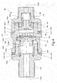
- FIG. 3 is a sectional view showing the residual pressure valve 30 of the embodiment of the present invention.
- the residual pressure valve 30 has a substantially cylindrical outer shape and includes an inlet port 110 connected to the air pressure piping 35 and a caliper side port 120 connected to the inlet portion 18.
- the residual pressure valve 30 is formed by connecting a valve housing 100, the inlet port 110 with a vent hole 110a and the caliper side port 120 with a vent hole 120a in an axial direction.
- the inlet port 110 and the caliper side port 120 are respectively fixed to the valve housing 100 by threadable engagement.
- a seat member 200 and a packing 210 are respectively interposed between the inlet port 110 and the valve housing 100 and between the caliper side port 120 and the valve housing 100 to prevent the leakage of passing air.
- the valve housing 100 has a cylindrical outer shape and is internally formed with a hollow portion.
- the valve housing 100 is formed with a partition wall 101 which divides the hollow portion inside the valve housing 100 into a first hollow portion 100c and a second hollow portion 100d in the axial direction.
- the cylindrical first hollow portion 100c and the cylindrical second hollow portion 100d are respectively formed at the inlet port 100 side and at the caliper side port 120 side of the partition wall 101.
- the first hollow portion 100c is open toward the vent hole 110a.
- the second hollow portion 100d is open toward the vent hole 120a.
- a second vent hole 100a penetrates through the partition wall 101 in the center.
- a plurality of vent holes 100b penetrate around the second vent hole 100a.
- the inlet port 110 with the vent hole 110a is threadably engaged with the valve housing 100.
- An open part of the first hollow portion 100c is sealed by the inlet port 110, whereas the first hollow portion 100c communicates with the vent hole 110a.
- a first valve seat 130 is provided slidably in the axial direction. The first valve seat 130 is biased toward the vent hole 120a by a first spring 160.
- a vent hole 130a penetrates through the first valve seat 130 in a central part thereof.
- the vent hole 130a communicates with the second vent hole 100a.
- the first valve seat 130 includes a seat member 180 in a part facing the first vent hole 100b.
- the seat member 180 closes the first vent hole 1 00b when the first valve seat 130 is closed and held in contact with the partition wall 101.
- the caliper side port 120 with the vent hole 120a is threadably engaged with the valve housing 100.
- An open part of the second hollow portion 100d is sealed by the caliper side port 120, and the second hollow portion 100d communicates with the vent hole 120a.
- a second valve seat 140 is provided slidably in the axial direction. The second valve seat 140 is biased toward the vent hole 110a by a second spring 170.
- a step portion 140a having a diameter smaller than an outer diameter of the second valve seat 140 is formed on the vent hole 120a side of the second valve seat 140.
- a spacer 150 is fitted around the step portion 140a.
- the spacer 150 is mounted in the second hollow portion 100d so that a clearance is formed between the spacer 150 and the inner wall of the valve housing 100.
- a vent hole 150a penetrates through the spacer 150.
- the second valve seat 140 includes a seat member 190 in a part facing the second vent hole 100a.
- the seat member 190 closes the second vent hole 100a when the second valve seat 140 is closed and held in contact with the partition wall 101.
- FIG. 4 is a diagram of the residual pressure valve 30 of the embodiment of the present invention when the brake is applied.
- the air from the unillustrated air pressure source is supplied to the drive pressure chamber 63 of the caliper brake device 1 via the air pressure piping 35 and the residual pressure valve 30 shown in FIG. 1 .
- the air is supplied from the vent hole 110a to the vent hole 120a in the residual pressure valve 30.
- the first valve seat 130 is held in contact with the partition wall 101 by a biasing force of the first spring 160 and the air pressure of the supplied air.
- the air passes from the second vent hole 100a through the clearances between the spacer 150 and the inner wall of the valve housing 100, and between the second valve seat 140 and the valve housing 100, and the vent hole 150a of the spacer 150 and is discharged to the vent hole 120a.
- the air discharged from the vent hole 120a is supplied from the inlet portion 18 shown in FIG. 1 to the drive pressure chamber 63 to press the piston 65, whereby the brake shoe 7 slides in contact with the disk 6 to brake the wheel 5.
- FIG. 5 is a diagram of the residual pressure valve 30 of the embodiment of the present invention when the brake release starts.
- the air pressure piping 35 is opened to the atmospheric pressure and the air in the drive pressure chamber 63 is discharged as described above.
- the air passes from the vent hole 120a toward the vent hole 110a.
- the second valve seat 140 comes into contact with the partition wall 101 by the biasing force of the second spring 170 and the air pressure of the passing air.
- the second hollow portion 100d and the first vent hole 100b communicate and the air passing through the residual pressure valve 30 passes through the first vent hole 100b to press the first valve seat 130 toward the vent hole 110a.
- the first valve seat 130 slides toward the vent hole 120a by the biasing force of the first spring 160 and comes into contact with the partition wall 101 (see FIG. 3 ).
- the first valve seat 130 is brought into contact with the partition wall 101 by the biasing force of the first spring 160, no more air is discharged from the drive pressure chamber 63 and the drive pressure chamber 63 is kept at a constant pressure.
- the air pressure of the drive pressure chamber 63 is set at a pressure which is smaller than the biasing forces of the return springs 44 so as not to cause the piston 65 to vibrate.
- the pressure at this time differs depending on the configuration of the caliper brake device 1, but is set, for example, at about 0.02 to 0.03 [Pa].
- the caliper brake device 1 of the embodiment of the present invention is composed of the brake shoes 7 for applying a friction force by sliding in contact with the disk 6 rotating together with the wheel 5, the caliper arms 12 supported on the vehicle and the actuator 60 for pressing the brake shoe 7 against the disk 6.
- the actuator 60 includes the elastic film 75 which is fixed to the caliper arm 12, the drive pressure chamber 63 which is defined by the elastic film 75 and to which air is supplied when the brake is applied, the residual pressure valve 30 which introduces the air to the drive pressure chamber, and the piston 65 which is interposed between the elastic film 75 and the brake shoe 7.
- the residual pressure valve 30 introduces the air to the drive pressure chamber 63 when the brake is applied while limiting the discharge of the air from the drive pressure chamber 63 when the brake is released.
- the residual pressure valve 30 can leave a certain amount of air in the drive pressure chamber 63 by limiting the discharge of the air from the drive pressure chamber 63 when the brake is released. This can maintain the swell of the elastic film 75 to an extent that the piston 65 does not bring the brake shoe 7 into sliding contact with the disk 6 and the piston 65 is pressed by the remaining air pressure even after the release of the brake. Thus, it is possible to prevent the vibration of the piston 65 in the caliper arm 12 and prevent the abrasion and breakage of the caliper brake device 1 due to vibration.
- the residual pressure valve 30 includes the first valve seat (first valve body) 130 biased toward the vent hole 120a by the first spring 160 and the second valve seat (second valve body) 140 biased toward the vent hole 110a by the second spring 170.
- the air is supplied to the drive pressure chamber 63 when the second valve seat 140 opens the second vent hole 100a, the air is discharged from the drive pressure chamber 63 when the first valve seat 130 opens the first vent hole 100b, and the discharge of the air from the drive pressure chamber 63 is limited when the first valve seat 130 and the second valve seat 140 close both the second vent hole 100a and the first vent hole 100b.
- the residual pressure valve 30 is composed of the first valve seat 130 and the second valve seat 140 biased by the first spring 160 and the second spring 170 in the valve housing 100, and can be formed to have a diameter substantially equal to the diameter of the air pressure piping 35.
- the outer shape of the residual pressure valve 30 is not enlarged, wherefore the discharge of the air from the drive pressure chamber 63 can be limited without changing the existing caliper brake device 1 and other constituent components.
- the first valve seat 130 is opened to discharge the air from the drive pressure chamber 63 if the air pressure by the air discharged from the drive pressure chamber 63 exceeds the biasing force of the first spring 160 when the brake is released.
- the first valve seat 130 is closed to stop the discharge of the air from the drive pressure chamber 63 if the air pressure by the air discharged from the drive pressure chamber 63 falls to or below the biasing force of the first spring 160.
- the discharge of the air from the drive pressure chamber 63 can be limited only by a mechanical movement of the residual pressure valve 30 and the abrasion and breakage of the caliper brake device I due to vibration can be prevented without increasing cost.
- the residual pressure valve 30 is formed with the first vent hole 100b that is closed regardless of whether the second valve seat 140 is open or closed when the first valve seat 130 is closed and the second vent hole 100a that is closed regardless of whether the first valve seat 130 is open or closed when the second valve seat 140 is closed.
- the second valve seat 140 is opened against the biasing force of the second spring 170 due to the air passing through the first vent hole 100b.
- the first valve seat 130 is opened against the biasing force of the first spring 160 due to the air passing through the second vent hole 100a.
- the first and second vent holes 100a, 100b have an orifice structure and can increase the air pressure due to the air passing through an orifice part and open and close the first valve seat 130 and the second valve seat 140. This can prevent the abrasion and breakage of the caliper brake device 1 due to vibration without increasing cost.
- the residual pressure valve 30 is configured to be easily detachable from the caliper arm 12, the usage of the residual pressure valve 30 detached is possible if it is not necessary to leave the air pressure in the drive pressure chamber 63 when the brake is released.
- the vibration of a hydraulic piston may be prevented by applying the residual pressure valve of embodiment to a hydraulic caliper brake device and keeping an internal pressure of a hydraulic piston chamber.
Landscapes
- Engineering & Computer Science (AREA)
- General Engineering & Computer Science (AREA)
- Mechanical Engineering (AREA)
- Transportation (AREA)
- Physics & Mathematics (AREA)
- Fluid Mechanics (AREA)
- Braking Arrangements (AREA)
- Valves And Accessory Devices For Braking Systems (AREA)
Abstract
Description
- The present invention relates to a caliper brake device for a vehicle, which applies a friction force to a disk rotating together with a wheel.
- A hydraulic brake device is used as a brake device used in a railway vehicle or the like. Hydraulic brake devices disclosed in
JP08-226469A JP08-226471A - The weight and cost of the hydraulic brake device increase due to the presence of the pneumatic-hydraulic converter and the hydraulic piping. Thus, it is desired to equip a railway vehicle with a pneumatic brake for operating the brake by an air pressure without using a hydraulic pressure.
-
JP2009-162245A - In the conventional pneumatic caliper brake device, the brake shoe is brought into sliding contact with a disk by supplying air to the diaphragm and pressing a piston by an air pressure when the brake is applied. When the brake is released, air is discharged from the diaphragm to reduce the air pressure and the piston is moved backward by a biasing force of a return spring.
- Since the pneumatic caliper brake device reduces the air pressure of the diaphragm when the brake is released, the piston is supported only by a supporting part surrounding the spring and the piston. In this case, there has been a problem that the piston in the caliper brake device vibrates due to vibration generated when the vehicle is in motion and, thereby, abrasion possibly occurs.
- Against such a problem, it is also conceivable to change an air pressure control system so that a slight amount of air pressure remains in the diaphragm also when the brake is released. However, there has been a problem that this change causes a cost increase and a weight increase.
- The present invention has been designated in consideration of those problems, and an object thereof is to provide a caliper brake device for vehicle which prevents abrasion caused by vibration without increasing cost and weight.
- According to one aspect of the present invention, a caliper brake device for vehicle for applying a friction force to a disk rotating together with a wheel is provided. The caliper brake device includes a brake shoe for exerting a friction force by sliding in contact with the disk; a caliper main body fixed to a vehicle; and an actuator for pressing the brake shoe against the disk; wherein the actuator includes an elastic film that is fixed to the caliper main body, a drive pressure chamber that is defined by the elastic film and to that a fluid is supplied, a valve that introduces the fluid to the drive pressure chamber, and a piston that is interposed between the elastic film and the brake shoe; the fluid is supplied to the drive pressure chamber and the elastic film swells toward the brake shoe when the brake is applied, whereby the piston brings the brake shoe into sliding contact with the disk; the supply of the fluid to the drive pressure chamber is stopped and the elastic film slackens when braking is released, whereby the piston moves the brake shoe away from the disk; and the valve introduces the fluid to the drive pressure chamber when the brake is applied while limiting the discharge of the fluid from the drive pressure chamber when the brake is released.
- An embodiment and advantages of the present invention are described in detail below with reference to the accompanying drawings.
-
-
FIG. 1 is a side view of a caliper brake device of an embodiment of the present invention. -
FIG. 2 is a sectional view of the caliper brake device of the embodiment of the present invention. -
FIG. 3 is a sectional view of a residual pressure valve of embodiment of the present invention. -
FIG. 4 is a sectional view of the residual pressure valve of the embodiment of the present invention when the brake is applied. -
FIG. 5 is a sectional view of the residual pressure valve of the embodiment of the present invention when the brake is released. -
FIG. 1 is a side view of acaliper brake device 1 of an embodiment of the present invention, andFIG. 2 is a sectional view along line II-II ofFIG. 1 . The configuration of thecaliper brake device 1 is described with three axes X, Y and Z perpendicular to each other set, wherein the X axis extends in a horizontal lateral direction, the Y axis extends in a vertical direction and the Z axis extends in a horizontal front-back direction. InFIG. 2 , denoted by H is a center line of awheel 5. - The
caliper brake device 1 mounted in a railway vehicle brakes the rotation of thewheel 5 by sandwiching adisk 6 of thewheel 5 between a pair ofbrake shoes 7. - A caliper
main body 10 is supported on a supportingframe 20 fixed to an unillustrated carriage (vehicle body) of the railway vehicle in a floating manner so as to be slidable in an X-axis direction by upper andlower slide pins - The caliper
main body 10 includes a pair ofcaliper arms 12 extending to straddle thedisk 6 of thewheel 5 and ayoke portion 13 connecting the left andright caliper arms 12. - An
adjuster 41 is fastened to each of upper and lower end parts of theright caliper arm 12 viaanchor bolts 42. The upper andlower adjusters 41 include ananchor pin 43 projecting in the X-axis direction. Both end parts of thebrake shoe 7 and a supportingplate 8 are respectively supported via theanchor pins 43. - The
brake shoe 7 includes alining 9 as a friction member which slides in contact with thedisk 6 and alining back plate 19 which is made of metal and to which a back part of thelining 9 is attached. - The
brake shoe 7 is supported by the supportingplate 8 via theanchor pins 43. Thebrake shoe 7 is supported movably back and forth relative to thedisk 6 by engaging the upper and lower end parts of the supportingplate 8 with therespective anchor pins 43, and a brake reaction force is supported by engaging upper and lower end parts of thelining back plate 19 with therespective anchor pins 43. - A rubber boot (not shown) for covering an exposed part of the
anchor pin 43 is mounted on theadjuster 41 to protect theadjuster 41 with the boot from dust. - The
adjuster 41 includes areturn spring 44 for biasing thebrake shoe 7 in a direction away from thedisk 6 via theanchor pin 43 and aclearance adjusting mechanism 45 for adjusting a clearance S between thebrake shoe 7 and thedisk 6 to be substantially constant when the brake is released. - When the brake is released, the
brake shoe 7 is moved away from thedisk 6 by biasing forces of thereturn springs 44 and the clearance S between thebrake shoe 7 and thedisk 6 is kept substantially constant by theclearance adjusting mechanisms 45. - The unillustrated left caliper arm is integrally formed with a supporting rail. The supporting rail is formed with a dovetail groove, and a lining back plate of the left brake shoe is inserted into the dovetail groove. The brake shoe is inserted into the supporting rail, and the upper and lower ends thereof are engaged with anchor blocks to be retained and fixed to the left caliper arm.
- The
right caliper arm 12 is provided with anactuator 60 for pressing thebrake shoe 7 toward thedisk 6 via the supportingplate 8. Theactuator 60 is arranged between therespective adjusters 41. - Air as a fluid is supplied to a
drive pressure chamber 63 of theactuator 60 from an air pressure source mounted in the railway vehicle, and anelastic film 75 presses thebrake shoe 7 via apiston 65 by an air pressure as a fluid pressure. - The
actuator 60 includes ahousing wall 12b formed in thecaliper arm 12, theelastic film 75 mounted on thehousing wall 12b, acover 92 fastened to thehousing 12b, thedrive pressure chamber 63 defined between thehousing wall 12b, theelastic film 75 and thecover 92, and thepiston 65 interposed between theelastic film 75 and thebrake shoe 7. The air pressure is increased by the air introduced to thedrive pressure chamber 63 and theelastic film 75 presses thebrake shoe 7 in the X-axis direction, whereby thebrake shoe 7 is pressed against thedisk 6. - As shown in
FIG 1 , thehousing wall 12b is in the form of an elliptical cylindrical surface penetrating through thecaliper arm 12. Thehousing wall 12b is formed to have a substantially elliptical cross-section facing thelining 9 over a wide range. - Without being limited to this, the
housing wall 12b may be shaped to have an arcuate cross-section extending along thelining 9. - The
caliper arm 12 includes anannular mounting seat 12a extending along an opening edge part of thehousing wall 12b. A plurality of screw holes are formed at predetermined intervals on themounting seat 12a, and thecover 92 is fastened viabolts 84 screwed into the respective screw holes. Aperipheral edge portion 76 of theelastic film 75 is sandwiched between themounting seat 12a and thecover 92. - The
cover 92 has a substantially elliptical outer shape similarly to themounting seat 12a. A part of thecover 92 defining thedrive pressure chamber 63 has a concave dish-like shape. - The
elastic film 75 is made of an elastic resin material. Theelastic film 75 may be formed into bellows using a composite material of an elastic resin material and a reinforcing material, for example, such as carbon fibers or Kepler fibers. Theelastic film 75 may also be formed using bellows made of a metal thin plate, a rubber tube or a diaphragm. - The
elastic film 75 includes theperipheral edge portion 76 sandwiched between themounting seat 12a and thecover 92, abellows portion 77 which extends and contracts along thehousing wall 12b, and apressing portion 79 facing thebrake shoe 7. - The
piston 65 is interposed between thepressing portion 79 of theelastic film 75 and thebrake shoe 7. Thepiston 65 comes into contact with thebrake shoe 7 through an opening formed in the supportingplate 8 to transmit a movement of theelastic film 75 to thebrake shoe 7. Thepiston 65 is fastened to the supportingplate 8 via akey 66. - The
caliper arm 12 includes aninlet portion 18. An air pressure piping 35 communicating with the unillustrated air pressure source and aresidual pressure valve 30 for introducing air supplied from the air pressure piping 35 to theinlet portion 18 are connected to theinlet portion 18. Pressurized air from the air pressure source is supplied from the air pressure piping 35 via an unillustrated switching valve to thedrive pressure chamber 63 via theresidual pressure valve 30 and theinlet portion 18. The switching valve operates in response to a command from an unillustrated controller and introduces the pressurized air from the air pressure source to thedrive pressure chamber 63 when the brake is applied while introducing an atmospheric pressure to thedrive pressure chamber 63 when the brake is released. - Next, the operation of the
caliper brake device 1 is described. - When the brake is applied, the air pressure is increased by the air introduced from the
inlet portion 18 to thedrive pressure chamber 63, whereby theelastic film 75 swells toward thebrake shoe 7 and presses thebrake shoe 7 against thedisk 6 via thepiston 65. This causes thebrake shoe 7 to apply a friction force to thedisk 6 to brake the rotation of thewheel 5. - When the brake is released, the air in the
drive pressure chamber 63 is discharged from theinlet portion 18 and the air pressure is reduced to a level lower than that when the brake is applied, whereby theelastic film 75 slackens, thebellows portion 77 and thepressing portion 79 contract, and thebrake shoe 7 is moved away from thedisk 6 by the biasing forces of the return springs 44. At this time, the clearance S between thebrake shoe 7 and thedisk 6 is adjusted to be substantially constant by theclearance adjusting mechanisms 45. - In this way, in the
caliper brake device 1, the air in thedrive pressure chamber 63 is discharged from theinlet portion 18 and the air pressure of thedrive pressure chamber 63 decreases when the brake is released. As the air pressure decreases, thebellows portion 77 and thepressing portion 79 of theelastic film 75 contract and thepiston 65 is released from pressing. At this time, thepiston 65 is moved away from thedisk 6 by the biasing forces of the return springs 44. - In the conventional pneumatic brake, the air pressure of the
drive pressure chamber 63 becomes substantially equal to an atmospheric pressure and thepiston 65 is biased toward a brake release side by the biasing forces of the return springs 44. - At this time, the
piston 65 is not pressed by thebellows portion 77 and thepressing portion 79 of theelastic film 75. Thus, if vibration is applied to thecaliper brake device 1, thepiston 65 vibrates and constituent components of thecaliper brake device 1 including thepiston 65 may be abraded or broken. - Against such a problem, it is conceivable to add a mechanism for controlling the air pressure from the air pressure source of the vehicle also when the brake is released. However, the addition of this mechanism requires a drastic change in a brake system and leads to a cost and a weight increase.
- Accordingly, in the embodiment of the present invention, the abrasion and breakage of the
caliper brake device 1 caused by vibration are prevented without largely increasing cost and weight by a characteristic configuration as described next. - In the embodiment of the present invention, the
residual pressure valve 30 for introducing the air supplied from the air pressure piping 35 to theinlet portion 18 is connected to thecaliper arm 12 as shown inFIG. 1 . By a configuration described below, theresidual pressure valve 30 limits the discharge of the air from thedrive pressure chamber 63 to keep the air pressure of thedrive pressure chamber 63 and prevent the vibration of thepiston 65 during a brake release period during which no air is supplied from the air pressure piping 35. -
FIG. 3 is a sectional view showing theresidual pressure valve 30 of the embodiment of the present invention. - The
residual pressure valve 30 has a substantially cylindrical outer shape and includes aninlet port 110 connected to the air pressure piping 35 and acaliper side port 120 connected to theinlet portion 18. - The
residual pressure valve 30 is formed by connecting avalve housing 100, theinlet port 110 with avent hole 110a and thecaliper side port 120 with avent hole 120a in an axial direction. Theinlet port 110 and thecaliper side port 120 are respectively fixed to thevalve housing 100 by threadable engagement. - A
seat member 200 and a packing 210 are respectively interposed between theinlet port 110 and thevalve housing 100 and between thecaliper side port 120 and thevalve housing 100 to prevent the leakage of passing air. - The
valve housing 100 has a cylindrical outer shape and is internally formed with a hollow portion. Thevalve housing 100 is formed with apartition wall 101 which divides the hollow portion inside thevalve housing 100 into a firsthollow portion 100c and a secondhollow portion 100d in the axial direction. The cylindrical firsthollow portion 100c and the cylindrical secondhollow portion 100d are respectively formed at theinlet port 100 side and at thecaliper side port 120 side of thepartition wall 101. The firsthollow portion 100c is open toward thevent hole 110a. The secondhollow portion 100d is open toward thevent hole 120a. - A
second vent hole 100a penetrates through thepartition wall 101 in the center. A plurality ofvent holes 100b penetrate around thesecond vent hole 100a. - The
inlet port 110 with thevent hole 110a is threadably engaged with thevalve housing 100. An open part of the firsthollow portion 100c is sealed by theinlet port 110, whereas the firsthollow portion 100c communicates with thevent hole 110a. In the firsthollow portion 100c, afirst valve seat 130 is provided slidably in the axial direction. Thefirst valve seat 130 is biased toward thevent hole 120a by afirst spring 160. - A
vent hole 130a penetrates through thefirst valve seat 130 in a central part thereof. Thevent hole 130a communicates with thesecond vent hole 100a. - The
first valve seat 130 includes aseat member 180 in a part facing thefirst vent hole 100b. Theseat member 180 closes thefirst vent hole 1 00b when thefirst valve seat 130 is closed and held in contact with thepartition wall 101. - The
caliper side port 120 with thevent hole 120a is threadably engaged with thevalve housing 100. An open part of the secondhollow portion 100d is sealed by thecaliper side port 120, and the secondhollow portion 100d communicates with thevent hole 120a. In the secondhollow portion 100d, asecond valve seat 140 is provided slidably in the axial direction. Thesecond valve seat 140 is biased toward thevent hole 110a by asecond spring 170. - A
step portion 140a having a diameter smaller than an outer diameter of thesecond valve seat 140 is formed on thevent hole 120a side of thesecond valve seat 140. Aspacer 150 is fitted around thestep portion 140a. Thespacer 150 is mounted in the secondhollow portion 100d so that a clearance is formed between thespacer 150 and the inner wall of thevalve housing 100. Avent hole 150a penetrates through thespacer 150. By thevent hole 150a of thespacer 150 or the clearance between thespacer 150 and the inner wall of thevalve housing 100, thefirst vent hole 100b formed in thepartition wall 101 and thevent hole 120a communicate in the secondhollow portion 100d regardless of the position of thesecond valve seat 140. - The
second valve seat 140 includes aseat member 190 in a part facing thesecond vent hole 100a. Theseat member 190 closes thesecond vent hole 100a when thesecond valve seat 140 is closed and held in contact with thepartition wall 101. - Next, the operation of the
residual pressure valve 30 thus configured is described. -
FIG. 4 is a diagram of theresidual pressure valve 30 of the embodiment of the present invention when the brake is applied. - When the brake is applied, the air from the unillustrated air pressure source is supplied to the
drive pressure chamber 63 of thecaliper brake device 1 via the air pressure piping 35 and theresidual pressure valve 30 shown inFIG. 1 . - At this time, the air is supplied from the
vent hole 110a to thevent hole 120a in theresidual pressure valve 30. Thefirst valve seat 130 is held in contact with thepartition wall 101 by a biasing force of thefirst spring 160 and the air pressure of the supplied air. - When the air pressure by the air supplied from the
second vent hole 100a communicating with thevent hole 130a exceeds a biasing force of thesecond spring 170, thesecond valve seat 140 slides toward thevent hole 120a. - The air passes from the
second vent hole 100a through the clearances between thespacer 150 and the inner wall of thevalve housing 100, and between thesecond valve seat 140 and thevalve housing 100, and thevent hole 150a of thespacer 150 and is discharged to thevent hole 120a. The air discharged from thevent hole 120a is supplied from theinlet portion 18 shown inFIG. 1 to thedrive pressure chamber 63 to press thepiston 65, whereby thebrake shoe 7 slides in contact with thedisk 6 to brake thewheel 5. -
FIG. 5 is a diagram of theresidual pressure valve 30 of the embodiment of the present invention when the brake release starts. - When the brake is released, the air pressure piping 35 is opened to the atmospheric pressure and the air in the
drive pressure chamber 63 is discharged as described above. - At this time, in the
residual pressure valve 30, the air passes from thevent hole 120a toward thevent hole 110a. Thesecond valve seat 140 comes into contact with thepartition wall 101 by the biasing force of thesecond spring 170 and the air pressure of the passing air. In this state, the secondhollow portion 100d and thefirst vent hole 100b communicate and the air passing through theresidual pressure valve 30 passes through thefirst vent hole 100b to press thefirst valve seat 130 toward thevent hole 110a. - When the air pressure by the air passing through the
first vent hole 100b exceeds the biasing force of thefirst spring 160, thefirst valve seat 130 slides toward thevent hole 110a. Therefore, the air passes from thevent hole 120a through the clearance between thespacer 150 and the inner wall of thevalve housing 100, thevent hole 150a of thespacer 150, the clearance between thesecond valve seat 140 and thevalve housing 100, thefirst vent hole 100b and thevent hole 130a and is output to thevent hole 110a. In this state, the air pressure of thedrive pressure chamber 63 is reduced by way of theresidual pressure valve 30. - When the air pressure of the
drive pressure chamber 63 is reduced and the air pressure by the air passing through thefirst vent hole 100b falls to or below the biasing force of thefirst spring 160, thefirst valve seat 130 slides toward thevent hole 120a by the biasing force of thefirst spring 160 and comes into contact with the partition wall 101 (seeFIG. 3 ). When thefirst valve seat 130 is brought into contact with thepartition wall 101 by the biasing force of thefirst spring 160, no more air is discharged from thedrive pressure chamber 63 and thedrive pressure chamber 63 is kept at a constant pressure. - At this time, a certain amount of air remains in the
drive pressure chamber 63, whereby a force is applied to thepiston 65 in a direction to press thebrake shoe 7 by the air pressure and, simultaneously, thebrake shoe 7 is biased in a direction away from thedisk 6 by the biasing forces of the return springs 44. Accordingly, thepiston 65 is pressed by a force in a positive and a negative direction on the X axis, wherefore the vibration of thepiston 65 relative to thecaliper arm 12 is suppressed even when thecaliper brake device 1 vibrates. When the air in thedrive pressure chamber 63 is not discharged by theresidual pressure valve 30 after the brake release as shown inFIG. 3 , the air pressure of thedrive pressure chamber 63 is set at a pressure which is smaller than the biasing forces of the return springs 44 so as not to cause thepiston 65 to vibrate. The pressure at this time differs depending on the configuration of thecaliper brake device 1, but is set, for example, at about 0.02 to 0.03 [Pa]. - As described above, the
caliper brake device 1 of the embodiment of the present invention is composed of thebrake shoes 7 for applying a friction force by sliding in contact with thedisk 6 rotating together with thewheel 5, thecaliper arms 12 supported on the vehicle and theactuator 60 for pressing thebrake shoe 7 against thedisk 6. Theactuator 60 includes theelastic film 75 which is fixed to thecaliper arm 12, thedrive pressure chamber 63 which is defined by theelastic film 75 and to which air is supplied when the brake is applied, theresidual pressure valve 30 which introduces the air to the drive pressure chamber, and thepiston 65 which is interposed between theelastic film 75 and thebrake shoe 7. Theresidual pressure valve 30 introduces the air to thedrive pressure chamber 63 when the brake is applied while limiting the discharge of the air from thedrive pressure chamber 63 when the brake is released. - Therefore, the
residual pressure valve 30 can leave a certain amount of air in thedrive pressure chamber 63 by limiting the discharge of the air from thedrive pressure chamber 63 when the brake is released. This can maintain the swell of theelastic film 75 to an extent that thepiston 65 does not bring thebrake shoe 7 into sliding contact with thedisk 6 and thepiston 65 is pressed by the remaining air pressure even after the release of the brake. Thus, it is possible to prevent the vibration of thepiston 65 in thecaliper arm 12 and prevent the abrasion and breakage of thecaliper brake device 1 due to vibration. - The
residual pressure valve 30 includes the first valve seat (first valve body) 130 biased toward thevent hole 120a by thefirst spring 160 and the second valve seat (second valve body) 140 biased toward thevent hole 110a by thesecond spring 170. The air is supplied to thedrive pressure chamber 63 when thesecond valve seat 140 opens thesecond vent hole 100a, the air is discharged from thedrive pressure chamber 63 when thefirst valve seat 130 opens thefirst vent hole 100b, and the discharge of the air from thedrive pressure chamber 63 is limited when thefirst valve seat 130 and thesecond valve seat 140 close both thesecond vent hole 100a and thefirst vent hole 100b. - Therefore, the discharge of the air from the
drive pressure chamber 63 can be limited only by the configuration of theresidual pressure valve 30 without changing thecaliper brake device 1 and the other configuration, and the abrasion and breakage of thecaliper brake device 1 due to vibration can be prevented without increasing cost and weight. Theresidual pressure valve 30 is composed of thefirst valve seat 130 and thesecond valve seat 140 biased by thefirst spring 160 and thesecond spring 170 in thevalve housing 100, and can be formed to have a diameter substantially equal to the diameter of the air pressure piping 35. Thus, the outer shape of theresidual pressure valve 30 is not enlarged, wherefore the discharge of the air from thedrive pressure chamber 63 can be limited without changing the existingcaliper brake device 1 and other constituent components. - In the
residual pressure valve 30, thefirst valve seat 130 is opened to discharge the air from thedrive pressure chamber 63 if the air pressure by the air discharged from thedrive pressure chamber 63 exceeds the biasing force of thefirst spring 160 when the brake is released. Thefirst valve seat 130 is closed to stop the discharge of the air from thedrive pressure chamber 63 if the air pressure by the air discharged from thedrive pressure chamber 63 falls to or below the biasing force of thefirst spring 160. - Therefore, the discharge of the air from the
drive pressure chamber 63 can be limited only by a mechanical movement of theresidual pressure valve 30 and the abrasion and breakage of the caliper brake device I due to vibration can be prevented without increasing cost. - The
residual pressure valve 30 is formed with thefirst vent hole 100b that is closed regardless of whether thesecond valve seat 140 is open or closed when thefirst valve seat 130 is closed and thesecond vent hole 100a that is closed regardless of whether thefirst valve seat 130 is open or closed when thesecond valve seat 140 is closed. When the brake is applied, thesecond valve seat 140 is opened against the biasing force of thesecond spring 170 due to the air passing through thefirst vent hole 100b. When the brake is released, thefirst valve seat 130 is opened against the biasing force of thefirst spring 160 due to the air passing through thesecond vent hole 100a. - Therefore, the discharge of the air from the
drive pressure chamber 63 can be limited only by a mechanical movement of theresidual pressure valve 30. The first andsecond vent holes first valve seat 130 and thesecond valve seat 140. This can prevent the abrasion and breakage of thecaliper brake device 1 due to vibration without increasing cost. - Since the
residual pressure valve 30 is configured to be easily detachable from thecaliper arm 12, the usage of theresidual pressure valve 30 detached is possible if it is not necessary to leave the air pressure in thedrive pressure chamber 63 when the brake is released. - Although the above embodiment of the present invention has been described, taking the pneumatic
caliper brake device 1 as an example, the vibration of a hydraulic piston may be prevented by applying the residual pressure valve of embodiment to a hydraulic caliper brake device and keeping an internal pressure of a hydraulic piston chamber. - Although the embodiment of the present invention has been described above, the above embodiment merely indicates some application examples of the present invention and is not meant to limit the technical scope of the present invention to the specific configuration of the above embodiment.
- The present application claims a priority based on Japanese Patent Application No.
2011-94812 - Exclusive nature or features of the embodiments of this invention are claimed as follows.
Claims (4)
- A caliper brake device for vehicle, which applies a friction force to a disk rotating together with a wheel, comprising:a brake shoe that exerts a friction force by sliding in contact with the disk;a caliper main body that is fixed to a vehicle body; andan actuator that presses the brake shoe against the disk;wherein:the actuator includes:an elastic film that is fixed to the caliper main body,a drive pressure chamber that is defined by the elastic film and to which a fluid is supplied,a valve that introduces the fluid to the drive pressure chamber, anda piston that is interposed between the elastic film and the brake shoe;the fluid is supplied to the drive pressure chamber and the elastic film swells toward the brake shoe when the brake is applied, whereby the piston brings the brake shoe into sliding contact with the disk;the supply of the fluid to the drive pressure chamber is stopped and the elastic film slackens when the brake is released, whereby the piston moves the brake shoe away from the disk; andthe valve introduces the fluid to the drive pressure chamber when the brake is applied and limits the discharge of the fluid from the drive pressure chamber when the brake is released.
- The caliper brake device for vehicle according to claim 1, wherein:the valve includes a hollow portion inside and is formed with a partition wall which divides the hollow portion into a first hollow portion and a second hollow portion in an axial direction and includes a first vent hole and a second vent hole;a first valve body that closes the first vent hole by coming into contact with the partition wall is provided in the first hollow portion;a second valve body that closes the second vent hole by coming into contact with the partition wall is provided in the second hollow portion;the fluid is supplied to the drive pressure chamber via the second vent hole when the second valve body is opened;the fluid is discharged from the drive pressure chamber via the first vent hole when the first valve body is opened; andthe discharge of the fluid from the drive pressure chamber is limited when both the first valve body and the second valve body are closed.
- The caliper brake device for vehicle according to claim 2, wherein:the first valve body is biased toward the partition wall by a spring; andthe valve is configured such that, when the brake is released, the first valve body is opened and the fluid is discharged from the drive pressure chamber if a pressure of the fluid discharged from the drive pressure chamber exceeds a biasing force of the spring and the first valve body is closed and the discharge of the fluid from the drive pressure chamber is stopped if the pressure of the fluid discharged from the drive pressure chamber falls to or below the biasing force of the spring.
- The caliper brake device for vehicle according to claim 3, wherein:the valve is configured such that the first valve body is opened against the biasing force of the spring due to a pressure of the fluid passing through the first vent hole when the brake is released.
Applications Claiming Priority (2)
| Application Number | Priority Date | Filing Date | Title |
|---|---|---|---|
| JP2011094812A JP5656729B2 (en) | 2011-04-21 | 2011-04-21 | Caliper brake device for vehicle |
| PCT/JP2012/060550 WO2012144549A1 (en) | 2011-04-21 | 2012-04-19 | Caliper brake device for vehicle |
Publications (2)
| Publication Number | Publication Date |
|---|---|
| EP2703683A1 true EP2703683A1 (en) | 2014-03-05 |
| EP2703683A4 EP2703683A4 (en) | 2015-12-09 |
Family
ID=47041655
Family Applications (1)
| Application Number | Title | Priority Date | Filing Date |
|---|---|---|---|
| EP12773607.2A Withdrawn EP2703683A4 (en) | 2011-04-21 | 2012-04-19 | CALIPER BRAKE DEVICE FOR VEHICLE |
Country Status (8)
| Country | Link |
|---|---|
| US (1) | US9327702B2 (en) |
| EP (1) | EP2703683A4 (en) |
| JP (1) | JP5656729B2 (en) |
| CN (1) | CN103502676B (en) |
| AU (1) | AU2012246577B2 (en) |
| BR (1) | BR112013025983A2 (en) |
| RU (1) | RU2557097C2 (en) |
| WO (1) | WO2012144549A1 (en) |
Families Citing this family (4)
| Publication number | Priority date | Publication date | Assignee | Title |
|---|---|---|---|---|
| JP6225063B2 (en) * | 2014-04-15 | 2017-11-01 | Kyb株式会社 | Caliper brake device |
| BR112017002552B1 (en) * | 2014-08-15 | 2022-07-19 | New York Air Brake Llc | BRAKE CYLINDER LIMITING VALVE |
| FR3098178B1 (en) | 2019-07-03 | 2021-07-30 | Tallano Tech | Workpiece securing system mounted on sole holder |
| US12479411B2 (en) * | 2022-09-30 | 2025-11-25 | Zf Active Safety Gmbh | Method for operating a vehicle brake system, and vehicle brake system |
Family Cites Families (26)
| Publication number | Priority date | Publication date | Assignee | Title |
|---|---|---|---|---|
| US1832393A (en) * | 1928-12-24 | 1931-11-17 | Hildebrand Wilhelm | Single chamber compressed air brake |
| DE687859C (en) * | 1938-04-03 | 1940-02-07 | Fichtel & Sachs Akt Ges | shock absorbers to equalize the air pressure within a piston rod protecting and centering |
| US2385625A (en) * | 1943-12-18 | 1945-09-25 | Arthur H Hopmans | Hydraulic transmission system |
| US2934080A (en) * | 1958-08-27 | 1960-04-26 | New York Air Brake Co | Valve |
| US3067770A (en) * | 1959-10-29 | 1962-12-11 | Siegler Inc | Two-way pressure responsive flow valve |
| US3526171A (en) * | 1968-09-16 | 1970-09-01 | Bendix Corp | Rolling diaphragm reinforcement |
| US3645362A (en) * | 1970-05-04 | 1972-02-29 | Gen Motors Corp | Kickback control and wear adjustment mechanism for disc brake |
| US3993171A (en) * | 1975-05-21 | 1976-11-23 | Tonn Erwin W | Fluid seal piston and cylinder assembly for a disc brake |
| JPS58166178A (en) * | 1982-03-29 | 1983-10-01 | Hino Motors Ltd | Double check valve |
| DE3326823A1 (en) * | 1983-07-26 | 1985-02-07 | Alfred Teves Gmbh, 6000 Frankfurt | HYDRAULICALLY ACTUATED WHEEL BRAKE |
| JPS6235123A (en) * | 1985-08-07 | 1987-02-16 | Sumitomo Electric Ind Ltd | Disk brake |
| EP0240625A1 (en) * | 1986-04-07 | 1987-10-14 | Tokico Ltd. | Disc brake |
| JP3665098B2 (en) * | 1995-02-23 | 2005-06-29 | 曙ブレーキ工業株式会社 | Caliper brake device for railway vehicles |
| JPH08226471A (en) * | 1995-02-23 | 1996-09-03 | Akebono Brake Ind Co Ltd | Caliper brake device for rolling stock |
| DE19525948A1 (en) * | 1995-07-17 | 1997-01-23 | Schaeffler Waelzlager Kg | Step valve |
| US5950670A (en) * | 1996-12-05 | 1999-09-14 | Rayco Manufacturing Inc. | Vacuum cup safety device |
| JPH11230212A (en) * | 1998-02-10 | 1999-08-27 | Akebono Brake Ind Co Ltd | Air disc brake |
| JP4041214B2 (en) * | 1998-05-26 | 2008-01-30 | 曙ブレーキ工業株式会社 | Unit brake device |
| US20080135110A1 (en) * | 2006-12-08 | 2008-06-12 | Honeywell International, Inc. | Bi-directional positive/negative pressure relief valve |
| JP5156325B2 (en) * | 2007-10-11 | 2013-03-06 | カヤバ工業株式会社 | Caliper brake device for vehicle |
| JP5312784B2 (en) * | 2007-12-28 | 2013-10-09 | カヤバ工業株式会社 | Caliper brake device for vehicle |
| RU2390449C2 (en) * | 2008-01-09 | 2010-05-27 | Открытое акционерное общество "Транспневматика" | Railway rallong stock vehicle disk brake |
| US7997296B2 (en) * | 2008-10-16 | 2011-08-16 | Swo-Chung Chai | Air valve device |
| US8162111B2 (en) * | 2008-12-12 | 2012-04-24 | GM Global Technology Operations LLC | Brake caliper with reduced brake squeal |
| JP5406632B2 (en) | 2009-08-25 | 2014-02-05 | カヤバ工業株式会社 | Caliper brake device |
| JP5330155B2 (en) * | 2009-08-25 | 2013-10-30 | カヤバ工業株式会社 | Caliper brake device |
-
2011
- 2011-04-21 JP JP2011094812A patent/JP5656729B2/en not_active Expired - Fee Related
-
2012
- 2012-04-19 EP EP12773607.2A patent/EP2703683A4/en not_active Withdrawn
- 2012-04-19 AU AU2012246577A patent/AU2012246577B2/en not_active Ceased
- 2012-04-19 BR BR112013025983A patent/BR112013025983A2/en not_active IP Right Cessation
- 2012-04-19 WO PCT/JP2012/060550 patent/WO2012144549A1/en not_active Ceased
- 2012-04-19 US US14/112,729 patent/US9327702B2/en not_active Expired - Fee Related
- 2012-04-19 RU RU2013141252/11A patent/RU2557097C2/en not_active IP Right Cessation
- 2012-04-19 CN CN201280018933.2A patent/CN103502676B/en not_active Expired - Fee Related
Also Published As
| Publication number | Publication date |
|---|---|
| CN103502676A (en) | 2014-01-08 |
| WO2012144549A1 (en) | 2012-10-26 |
| AU2012246577B2 (en) | 2016-02-25 |
| RU2013141252A (en) | 2015-05-27 |
| JP2012225448A (en) | 2012-11-15 |
| RU2557097C2 (en) | 2015-07-20 |
| CN103502676B (en) | 2016-02-24 |
| AU2012246577A1 (en) | 2013-11-07 |
| BR112013025983A2 (en) | 2017-11-07 |
| US9327702B2 (en) | 2016-05-03 |
| US20140054117A1 (en) | 2014-02-27 |
| EP2703683A4 (en) | 2015-12-09 |
| JP5656729B2 (en) | 2015-01-21 |
Similar Documents
| Publication | Publication Date | Title |
|---|---|---|
| JP5312784B2 (en) | Caliper brake device for vehicle | |
| KR101853771B1 (en) | Device for regulate of flex brake pedal feeling | |
| JP5406632B2 (en) | Caliper brake device | |
| US9169883B2 (en) | Caliper brake device for vehicle | |
| US9327702B2 (en) | Caliper brake device for a vehicle | |
| JP2013194917A (en) | Spring brake actuator with caging bolt bearing joining pressure plate and actuator tube | |
| CN101568743B (en) | Caliper brake device for vehicle | |
| US20140216864A1 (en) | Caliper brake apparatus | |
| CN102574519A (en) | Play adjustment in a hydraulic braking system | |
| JP4885109B2 (en) | Caliper brake device for vehicle | |
| JP4879138B2 (en) | Caliper brake device for vehicle | |
| JP5330155B2 (en) | Caliper brake device | |
| JP6663266B2 (en) | Brake equipment | |
| JP5390466B2 (en) | Caliper brake device | |
| JP5622561B2 (en) | Caliper brake device | |
| JP2011047427A (en) | Caliper brake device | |
| JP5484979B2 (en) | Caliper brake device | |
| JP5663636B2 (en) | Caliper brake device | |
| JP2002188669A (en) | Adjuster mechanism for clearance | |
| US10336308B2 (en) | Brake device for vehicle | |
| JP5613803B2 (en) | Caliper brake device | |
| JP2012035672A (en) | Caliper braking device |
Legal Events
| Date | Code | Title | Description |
|---|---|---|---|
| PUAI | Public reference made under article 153(3) epc to a published international application that has entered the european phase |
Free format text: ORIGINAL CODE: 0009012 |
|
| 17P | Request for examination filed |
Effective date: 20130918 |
|
| AK | Designated contracting states |
Kind code of ref document: A1 Designated state(s): AL AT BE BG CH CY CZ DE DK EE ES FI FR GB GR HR HU IE IS IT LI LT LU LV MC MK MT NL NO PL PT RO RS SE SI SK SM TR |
|
| DAX | Request for extension of the european patent (deleted) | ||
| RA4 | Supplementary search report drawn up and despatched (corrected) |
Effective date: 20151105 |
|
| RIC1 | Information provided on ipc code assigned before grant |
Ipc: B60T 15/30 20060101ALI20151030BHEP Ipc: F16D 65/14 20060101ALI20151030BHEP Ipc: B60T 15/22 20060101ALI20151030BHEP Ipc: F16D 65/18 20060101AFI20151030BHEP Ipc: B60T 15/54 20060101ALI20151030BHEP Ipc: B61H 5/00 20060101ALI20151030BHEP |
|
| RAP1 | Party data changed (applicant data changed or rights of an application transferred) |
Owner name: KYB CORPORATION |
|
| STAA | Information on the status of an ep patent application or granted ep patent |
Free format text: STATUS: THE APPLICATION HAS BEEN WITHDRAWN |
|
| 18W | Application withdrawn |
Effective date: 20190104 |