EP2702860A1 - Moissonneuse agricole automatique - Google Patents
Moissonneuse agricole automatique Download PDFInfo
- Publication number
- EP2702860A1 EP2702860A1 EP13170619.4A EP13170619A EP2702860A1 EP 2702860 A1 EP2702860 A1 EP 2702860A1 EP 13170619 A EP13170619 A EP 13170619A EP 2702860 A1 EP2702860 A1 EP 2702860A1
- Authority
- EP
- European Patent Office
- Prior art keywords
- drive
- input shaft
- machine according
- harvesting machine
- shaft
- Prior art date
- Legal status (The legal status is an assumption and is not a legal conclusion. Google has not performed a legal analysis and makes no representation as to the accuracy of the status listed.)
- Granted
Links
- 238000003306 harvesting Methods 0.000 claims abstract description 33
- 239000004459 forage Substances 0.000 claims description 30
- 230000008878 coupling Effects 0.000 claims description 10
- 238000010168 coupling process Methods 0.000 claims description 10
- 238000005859 coupling reaction Methods 0.000 claims description 10
- 240000008042 Zea mays Species 0.000 abstract description 3
- 235000002017 Zea mays subsp mays Nutrition 0.000 abstract description 3
- 235000016383 Zea mays subsp huehuetenangensis Nutrition 0.000 abstract description 2
- 235000009973 maize Nutrition 0.000 abstract description 2
- 230000005540 biological transmission Effects 0.000 description 14
- 238000013461 design Methods 0.000 description 10
- 238000012423 maintenance Methods 0.000 description 6
- 241001124569 Lycaenidae Species 0.000 description 4
- 238000011161 development Methods 0.000 description 3
- 230000000694 effects Effects 0.000 description 3
- 241000196324 Embryophyta Species 0.000 description 2
- 238000009826 distribution Methods 0.000 description 2
- 235000005824 Zea mays ssp. parviglumis Nutrition 0.000 description 1
- 238000004140 cleaning Methods 0.000 description 1
- 238000010276 construction Methods 0.000 description 1
- 235000005822 corn Nutrition 0.000 description 1
- 238000005520 cutting process Methods 0.000 description 1
- 238000010586 diagram Methods 0.000 description 1
- 238000006073 displacement reaction Methods 0.000 description 1
- 238000009434 installation Methods 0.000 description 1
- 230000010354 integration Effects 0.000 description 1
- 239000000463 material Substances 0.000 description 1
- 238000012805 post-processing Methods 0.000 description 1
- 238000003825 pressing Methods 0.000 description 1
- 238000012545 processing Methods 0.000 description 1
- 230000001737 promoting effect Effects 0.000 description 1
- 238000011144 upstream manufacturing Methods 0.000 description 1
- 239000002023 wood Substances 0.000 description 1
Images


Classifications
-
- A—HUMAN NECESSITIES
- A01—AGRICULTURE; FORESTRY; ANIMAL HUSBANDRY; HUNTING; TRAPPING; FISHING
- A01D—HARVESTING; MOWING
- A01D69/00—Driving mechanisms or parts thereof for harvesters or mowers
- A01D69/06—Gearings
Definitions
- the invention relates to a self-propelled agricultural harvester according to the preamble of patent claim 1.
- Self-propelled agricultural harvesters such as in particular forage harvesters, can be equipped with harvesting attachments of various types for harvesting different types of crops.
- the harvesting attachment essentially serves to receive and convey crop material, while the actual processing, in the case of a forage harvester, the pre-pressing, the comminution ("shredding") and possibly the post-processing take place in the forage harvester itself.
- Harvesting attachments are usually attachable to the front of the harvester and are powered by this powered. That is, the drive power of the header is provided in some form by a main propulsion engine of the harvester. In a known manner, this is done, for example, mechanically by means of a drive shaft indirectly driven by the main engine on the machine side, which can be connected to the harvesting attachment via a shaft connection.
- a drive system for a header which has a power split transmission unit.
- a high efficiency mechanical driveline provides the main propulsion power while a hydraulic accessory driveline coupled thereto by the transmission unit provides a variable output speed for the header.
- the aforementioned disadvantages are thus largely eliminated.
- such a drive system is a considerable design effort with associated disadvantages.
- a self-propelled agricultural harvester with the features of claim 1.
- this is characterized in that the input shaft relative to the output shaft can be brought into drive connection and decoupled from it, wherein the drive connection comprises a force acting between input shaft and output shaft variator.
- a drive power driving the (attachable) header is first provided by the drive motor of the harvester.
- a gear arrangement whose input shaft is driven by the drive motor and whose output side output shaft can be brought into drive connection with the header device, serves to transmit the drive power to the header attachment.
- the input shaft relative to the output shaft in drive connection can be brought and decoupled from this, which in particular by a clutch can be implemented, which establishes or dissolves a drive connection between the input shaft and the output shaft.
- the drive connection comprises a variator gear acting between input and output shafts of the gear assembly.
- This can preferably be coupled to the input shaft and executed by this decoupled.
- these features make it possible first of all to be able to vary the rotational speed of the output shaft-and thus the speed of the header attachment-steplessly and during ongoing operation, at least over a certain range, by setting the variator gear to a desired gear ratio.
- the possibility is thus created to adapt the harvesting attachment during the harvesting operation in the speed of the respective conditions, assuming a corresponding drive option of the variator.
- a variator is an efficient way (ie with high efficiency) to transmit mechanical power with infinitely variable during operation adjustable speed.
- coupling capability is also possible to make or break the drive connection between the input and output shaft of the gear assembly.
- a smooth start-up of a mounted header or a drive interruption are thus possible.
- a clutch which is expediently used here can be arranged in different ways on the gear arrangement.
- the coupling is arranged so that the variator can be coupled by means of the clutch relative to the input shaft and decoupled from this. Consequently, the clutch is upstream of the variator transmission "on the drive side” so that the variator is not driven when the clutch is open. Unnecessary friction losses are thus avoided.
- the clutch is upstream of the variator transmission "on the drive side” so that the variator is not driven when the clutch is open. Unnecessary friction losses are thus avoided.
- the variator would always be in driving connection with the input shaft.
- the output shaft of the gear assembly would be drivably separable therefrom by means of the clutch downstream of the variator gearbox. The latter variant could be advantageous for reasons of lack of space in the input shaft, for example.
- the variator has a drive wheel with variable effective diameter, an axially parallel arranged output wheel with variable effective diameter and a traction means that endlessly wraps around the wheels at the respective effective diameter to produce between the wheels a drive connection with variable speed ratio.
- the traction means are in particular a tension belt, for example in the form of a wide V-belt.
- the drive wheel is associated with the input shaft of the transmission assembly and the output gear is associated with the output shaft of the transmission assembly.
- the drive wheel and the input shaft as well as the output gear and the output shaft can advantageously be arranged coaxially in each case. This results in the advantageous effect that the entire gear assembly is mapped with their functional elements by two axes.
- the gear arrangement can be advantageously developed by the drive wheel is rotatably mounted relative to the input shaft, the clutch is rotatably connected to the drive wheel and is operable to drive in a coupling state, the drive wheel to bring with the input shaft, and in a decoupled state, the drive wheel drivingly released from the input shaft.
- the drive wheel and the output gear each comprise two cone-like bodies, which are arranged coaxially with mutually facing tips and axially movable relative to each other, such that their lateral surfaces at least partially serve as a running surface for the traction means.
- This - known per se - design of a variator allows the relative axial mobility of the conical body to each other that the respective wheel is variable in its effective diameter.
- the axial actuation can take place in different ways, for example hydraulically, wherein it is preferable to set a different effective diameter and constructive that only one of the cone-like body is axially moved on a wheel, while the other body is axially immovable.
- a particularly compact design of the gear arrangement can be achieved by the clutch is rotatably connected to an axially immovable body of the drive wheel.
- the coupling is integrated in the drive wheel by this measure.
- the coupling with the drive wheel is designed as a unit which can be mounted on the input shaft.
- An advantageous development of the invention therefore provides that the output shaft of the transmission assembly is associated with a brake which is operable to decelerate the output shaft at least in the decoupled state.
- a brake which is operable to decelerate the output shaft at least in the decoupled state.
- the brake advantageously comprises a non-rotatably connected to the driven wheel friction body such as a disc (disc brake) and a machine side arranged braking device which is operable to be in a non-braking state free from the influence of force on the friction body, and in a Braking on the friction body to exert a rotational movement of the output shaft opposing force.
- a disc or drum could be attached to one of the cone-like bodies of the output gear.
- the brake could also be disposed on another portion of the output shaft (off the output gear), for example in the area of power transmission (e.g., angular gear) to the header drive shaft for the header.
- a useful for the integration into a harvester design of the invention is that the input shaft and the output shaft of the gear assembly are arranged parallel to each other.
- an advantageous development further provides that the input shaft of the gear arrangement corresponds to a drive shaft of a working unit of the harvesting machine, in particular the drive shaft of a chopping unit.
- the drive shaft of the working unit transverse to the machine longitudinal direction and through the working unit to be on a first side of the machine (relative to the machine longitudinal center axis) drivingly connected to the drive motor and on a second, opposite machine side (relative to the machine longitudinal center axis) drive there located gear assembly.
- the output shaft of the gear assembly is mounted on a feed housing of the harvester, which is connected laterally pivotable about an approximately vertical pivot axis with a main frame of the harvester.
- a compact construction and weight balanced development of the invention provides that the output shaft extends transversely to the machine longitudinal direction and through the feeder housing to be drivingly connected to the header on the first machine side and to record on the second, opposite side of the machine the driven gear of the gear assembly , Accordingly, there is a junction of the output shaft with the attachable header on the same side of the harvester as the drive of the working unit (chopper drum).
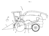
- Fig. 1 shows a schematic side view (seen from the left in the direction of travel FR) a self-propelled agricultural harvester, which is designed according to the single embodiment of the invention as a self-propelled forage harvester 1.
- a self-propelled agricultural harvester which is designed according to the single embodiment of the invention as a self-propelled forage harvester 1.
- the Forage harvester 1 comprises a drive motor 2 arranged at the rear, which serves to drive various units.
- a front side below the driver's cab (unspecified) arranged chopper drum 8 is driven by an endlessly circulating main drive belt 7, which serves in known manner for crushing and promoting crop.
- the main drive belt 7 drives further known manner further (unspecified) units of the forage harvester 1, to which the main drive belt 7 each wraps around the working units associated pulleys.
- the main drive belt 7 extends with respect to the indicated direction of travel FR of the forage harvester 1 on the left side of the machine.
- the forage harvester 1 is based on a machine frame 6. On the front side, based on the forward direction of travel FR of the forage harvester 1, there is a feeder housing 31, to which a header 4 such as a so-called maize header, a corn picker, a pickup, a whole plant cutting plant, a wood cutter or the like can be attached.
- the header 4 is driven by a header drive shaft 9 from the forage harvester 1 in a manner to be described in more detail.
- the forage harvester 1 has a special gear arrangement whose arrangement and function on the forage harvester 1 are based on Fig. 2 and 3 is explained, since essential elements of the gear assembly on the other (right), in Fig. 1 invisible side of the forage harvester.
- FIG. 2 shows Fig. 2 in perspective partial view a forage harvester 1 as from Fig. 1 known from the perspective of obliquely right front, with individual components have been omitted for improved visibility of inventive features.
- the right front wheel has been removed.
- An attachment is not attached to the forage harvester 1 for purposes of illustration.
- the forage harvester 1 has a gear arrangement 3 which, relative to the forward direction of travel FR on the right-hand side of the machine, namely, is arranged on the right side next to the (here concealed) chopper drum and the feeder housing 31.
- the transmission assembly 3 comprises as essential elements an input shaft 10, which is identical to the drive shaft of the cutterhead and is driven together with the cutterhead (see explanation of the cutterhead drive to Fig. 1 ), a parallel output side output shaft 20 and a variator 5, which can be coupled via a clutch 12 to the input shaft 10 and decoupled from this.
- the variator 5 has an input shaft 10 associated drive wheel 11, an output shaft 20 associated output gear 12 and a - Fig.
- - belt 30 (see Fig. 3 ), which endlessly wraps around the wheels 11, 21 for producing a drive connection between the shafts 10, 20. It is preferably a wide V-belt. To explain the closer operation of the gear assembly 3 is now on Fig. 3 directed.
- Fig. 3 shows a schematic representation of the invention essential part of a drive train of a self-propelled forage harvester 1 in section from above.
- the simplified illustrated drive train can be in a forage harvester 1 according to the Fig. 1 and 2 be installed. It should be noted that it is not a full scale or complete representation of the components of a forage harvester 1, but that a simplified representation has been selected for explanatory purposes.
- a forward direction FR equal machine longitudinal direction
- the machine centerline is collinear drawn as a dashed line.
- the machine sides S right and S left have been designated, which denote an area on the right side or left side of the machine center line - with respect to the forward direction FR.
- the forage harvester 1 has a machine frame 6, against which a feeder housing 31 is pivotably mounted about a vertically extending pivot axis 32.
- the pivoting movement of the feeder housing 31 is indicated by double arrows; it serves to the feed housing 31 for maintenance or cleaning purposes in a simple way laterally to fold, to have free access to the underlying chopper drum 8.
- the chopper drum 8 is mounted on a shaft 10, which is identical to the input shaft of the gear assembly 3, rotatably mounted relative to the machine frame 6.
- the shaft 10 driven by the main drive belt 7, which in turn can be brought into drive connection with the drive motor 2 (not shown here).
- Fig. 2 On the main drive belt 7 opposite side of the machine S right there already is too Fig. 2
- a variator gearbox 5 which can be coupled to the input shaft 10 and uncoupled therefrom.
- the variator gear 5 has a drive wheel 11 assigned to the input shaft 10, an output gear 21 arranged axially parallel thereto, and a belt 30 which is disposed between drive gear 11 and Output gear 21 produces a drive connection.
- both drive wheel 11 and driven wheel 21 have a variable effective diameter by the drive wheel 11 and the driven wheel 21 each having two cone-like (based on the outer shape) body 13, 14 and 23, 24, the coaxial arranged with mutually facing tips and are axially movable relative to each other.
- the lateral surfaces of the bodies 13, 14 and 23, 24 at least partially form a running surface for the rotating belt 30.
- the bevel gear 13 is axially immovable, while the bevel gear 14 is axially displaceable.
- the axial actuation of the bevel gear 14 takes place hydraulically, for which purpose an oil feed is incorporated through the input shaft 10, which is supplied via the oil line 18.
- the bevel gear 24 is axially immovable, while the bevel gear 23 is axially displaceable.
- the axial actuation of the bevel gear 23 is also carried out hydraulically, for which purpose an oil feed is incorporated through the output shaft 20, which is supplied via the oil line 28.
- the adjustment of the variator 5 is carried out starting from the drive wheel 11, ie by adjusting the bevel gear 14 via the oil line 18.
- the adjustment of the driven bevel gear 23 is enforced by the changed wrap of the drive wheel 11, wherein the oil line 28 serves in the belt 30 a maintain desired voltage, so hydraulically - regardless of the respectively set axial displacement (or the resulting speed ratio) - to achieve a desired belt bias.
- This can For example, be adapted to the advantageous to be transmitted to the belt 30 drive power to keep its wear low while ensuring a safe torque transmission.
- the input shaft 10 can be brought into driving connection with respect to the output shaft 20 and decoupled therefrom, wherein the drive connection comprises a variator 5 acting between the input shaft 10 and the output shaft 20.
- the drive wheel 11 is first rotatably mounted relative to the input shaft 10.
- a clutch 12 is rotatably connected to the drive wheel 11, which can be actuated between a clutch state and a decoupled state. In the uncoupled state, the drive wheel 11 is drivingly released from the input shaft 10 and thus freely rotatable relative to this.
- the clutch 12 may be of different design, in the embodiment shown is a dry clutch, which has a respect to the input shaft 10 non-rotatable clutch disc 15 and an opposite the clutch disc 15 axially displaceable friction body 16.
- the operation of the friction body 16 is hydraulically via an oil line 17.
- the clutch 12, the housing enclosing the clutch disc 15 and the axially movable friction body 16 is rotatably connected to the cone body 13 of the drive wheel 11.
- the clutch 12 is to - in the clutch state - to transmit torque from the input shaft 10 to the drive wheel 11.
- the clutch 12 is executed in the embodiment shown together with the drive wheel 11 as a structural unit and can be mounted on the input shaft 10 so.
- a comparatively compact design has the output shaft 20 associated brake 22.
- a disc brake other types of brake are conceivable, for example, a band, jaw, drum or disc brake.
- the clutch 12 is opened.
- the brake 22 rotatably connected to the driven gear 21st connected friction body in the form of a brake disc 25 and a machine side arranged braking device in the form of a brake caliper, which has two of the brake disc 25 opposite brake pads 26.
- the brake 22, in particular its brake pads 26 are hydraulically actuated via an oil line 27 to be free of force on the brake disk 25 in a non-braking state, and to exert a braking force on the brake disk 25 in a braking state, the rotational movement of the driven gear 21 or the thus non-rotatably connected output shaft 20 counteracts.
- the output shaft 20 is mounted opposite the feeder housing 31 of the forage harvester 1 and extends from the right side of the machine S right through the feeder housing 31 on the left side of the machine S left . Since the intake housing 31 for maintenance and repair purposes about the vertical pivot axis 32 is laterally pivotable (see double arrows), can be in a laterally pivoted maintenance condition (not shown) of the feed housing 31 of the thus relaxed belt 30 in a relatively simple manner by the wheels 11, 12 remove without tools or attach to these, for example for maintenance or repair purposes.
- FIG. 3 shows Fig. 3 in that the output shaft 20 drives an auxiliary drive shaft 9 projecting in the forward direction FR from the forage harvester 1 via a bevel gearbox.
- auxiliary drive shaft 9 projecting in the forward direction FR from the forage harvester 1 via a bevel gearbox.
- this shaft 9 can be seen in itself known and therefore not explained in more detail way to connect a header 4 drivably.
- the described forage harvester 1 achieves various advantages.
- a drive for an attachable harvest header is provided, which is under achieving a high efficiency even under load continuously adjustable drive speed is possible.
- the drive by means of the proposed clutch is switched on and off, with a corresponding operation advantageous also a smooth start of the header is possible.
- a Schnellstopfunktion is created by the output side brake arranged. Due to the hydraulically preloaded output gear, the belt can also be kept at a desired voltage regardless of the position of the variator.
- clutch and brake are within the scope of the invention.
- the clutch could be assigned to the output shaft of the gearbox assembly, that is, downstream of the variator gearbox.
- brake could be arranged on the opposite (first) machine side, for example in the region of an in Fig. 3 shown gear stage (angle gear) between the output shaft 20 and auxiliary drive shaft.
Landscapes
- Life Sciences & Earth Sciences (AREA)
- Environmental Sciences (AREA)
- Harvester Elements (AREA)
Applications Claiming Priority (1)
| Application Number | Priority Date | Filing Date | Title |
|---|---|---|---|
| DE102012107958.7A DE102012107958A1 (de) | 2012-08-29 | 2012-08-29 | Selbstfahrende landwirtschaftliche Erntemaschine |
Publications (2)
| Publication Number | Publication Date |
|---|---|
| EP2702860A1 true EP2702860A1 (fr) | 2014-03-05 |
| EP2702860B1 EP2702860B1 (fr) | 2017-12-20 |
Family
ID=48576284
Family Applications (1)
| Application Number | Title | Priority Date | Filing Date |
|---|---|---|---|
| EP13170619.4A Active EP2702860B1 (fr) | 2012-08-29 | 2013-06-05 | Moissonneuse agricole autonome |
Country Status (2)
| Country | Link |
|---|---|
| EP (1) | EP2702860B1 (fr) |
| DE (1) | DE102012107958A1 (fr) |
Cited By (1)
| Publication number | Priority date | Publication date | Assignee | Title |
|---|---|---|---|---|
| CN103858610A (zh) * | 2014-03-10 | 2014-06-18 | 郑宇虎 | 一种收割机用驱动桥 |
Citations (6)
| Publication number | Priority date | Publication date | Assignee | Title |
|---|---|---|---|---|
| US2336002A (en) * | 1941-11-21 | 1943-12-07 | Massey Harris Co | Variable speed transmission and clutch |
| US3466854A (en) * | 1966-05-19 | 1969-09-16 | Massey Ferguson Ind Ltd | Ground speed responsive variable drive for crop handling apparatus |
| DE2745564A1 (de) * | 1976-10-26 | 1978-04-27 | Deere & Co | Antriebsvorrichtung fuer antreibbare arbeitsorgane einer erntebergungsvorrichtung |
| DE3048255A1 (de) * | 1980-01-28 | 1981-12-03 | Deere & Co., Niederlassung Deere & Co. European Office 6800 Mannheim, Moline, Ill. | Antriebsvorrichtung fuer eine landwirtschaftlich genutzte maschine, insbesondere maehdrescher |
| US20030109292A1 (en) * | 2001-12-12 | 2003-06-12 | Schroeder Jay D. | Hydro-mechanical variable speed feeder/header drive for an agricultural combine |
| EP2281434A2 (fr) | 2009-07-30 | 2011-02-09 | CLAAS Saulgau GmbH | Appareil doté d'un dispositif de transport transversal et d'une adaptation de couple |
-
2012
- 2012-08-29 DE DE102012107958.7A patent/DE102012107958A1/de not_active Withdrawn
-
2013
- 2013-06-05 EP EP13170619.4A patent/EP2702860B1/fr active Active
Patent Citations (6)
| Publication number | Priority date | Publication date | Assignee | Title |
|---|---|---|---|---|
| US2336002A (en) * | 1941-11-21 | 1943-12-07 | Massey Harris Co | Variable speed transmission and clutch |
| US3466854A (en) * | 1966-05-19 | 1969-09-16 | Massey Ferguson Ind Ltd | Ground speed responsive variable drive for crop handling apparatus |
| DE2745564A1 (de) * | 1976-10-26 | 1978-04-27 | Deere & Co | Antriebsvorrichtung fuer antreibbare arbeitsorgane einer erntebergungsvorrichtung |
| DE3048255A1 (de) * | 1980-01-28 | 1981-12-03 | Deere & Co., Niederlassung Deere & Co. European Office 6800 Mannheim, Moline, Ill. | Antriebsvorrichtung fuer eine landwirtschaftlich genutzte maschine, insbesondere maehdrescher |
| US20030109292A1 (en) * | 2001-12-12 | 2003-06-12 | Schroeder Jay D. | Hydro-mechanical variable speed feeder/header drive for an agricultural combine |
| EP2281434A2 (fr) | 2009-07-30 | 2011-02-09 | CLAAS Saulgau GmbH | Appareil doté d'un dispositif de transport transversal et d'une adaptation de couple |
Cited By (1)
| Publication number | Priority date | Publication date | Assignee | Title |
|---|---|---|---|---|
| CN103858610A (zh) * | 2014-03-10 | 2014-06-18 | 郑宇虎 | 一种收割机用驱动桥 |
Also Published As
| Publication number | Publication date |
|---|---|
| DE102012107958A1 (de) | 2014-06-05 |
| EP2702860B1 (fr) | 2017-12-20 |
Similar Documents
| Publication | Publication Date | Title |
|---|---|---|
| EP1609351B1 (fr) | Entraînement d'une tête de récolte | |
| EP1570724B1 (fr) | Disposition d'actionnement pour actionner la tête de récolte d'une machine de récolte | |
| EP2145524B1 (fr) | Moissonneuse agricole | |
| EP2404496B1 (fr) | Cueilleur à maïs | |
| EP3906770B1 (fr) | Système d'entraînement pour un engin d'abattage-façonnage autonome | |
| EP2281434B1 (fr) | Appareil attaché doté d'un dispositif de transport transversal et d'une adaptation de vitesse de rotation | |
| EP2687079A2 (fr) | Appareil frontal fonctionnant indépendamment des rangées destiné à récolter des produits de récolte à tiges | |
| BE1024973B1 (de) | Antriebsanordnung zum drehzahlveränderbaren Antrieb einer mit zwei Konditionierwalzen ausgestatteten Konditioniereinrichtung eines Feldhäckslers | |
| EP2407022B1 (fr) | Machine destinée à la récolte de plantes de type à tiges avec dispositif de découpe à moteur électrique | |
| EP0860106A1 (fr) | Machine pour faucher du mais et des plantes à tiges similaires | |
| DE102015206845A1 (de) | Schneidwerk zur Ganzpflanzenernte | |
| DE102006030971A1 (de) | Antriebssystem einer landwirtschaftlichen Arbeitsmaschine | |
| BE1026188B1 (de) | Feldhäcksler mit schnittlängenabhängiger Drehzahl der Konditioniereinrichtung | |
| DE102009028094B4 (de) | Selbstfahrende Erntemaschine | |
| EP2132975B1 (fr) | Système d'entraînement pour une moissonneuse | |
| EP2774473B1 (fr) | Moissonneuse automotrice | |
| EP2702860B1 (fr) | Moissonneuse agricole autonome | |
| EP1566090B1 (fr) | Machine pour couper des plantes à tige | |
| DE102006030954B4 (de) | Antriebssystem einer landwirtschaftlichen Arbeitsmaschine | |
| EP0025848B1 (fr) | Véhicule automoteur muni d'instruments de travail, en particulier véhicule agricole | |
| DE202011002195U1 (de) | Selbstfahrende landwirtschaftliche Erntemaschine mit einem elektromotorisch angetriebenen Arbeitsorgan | |
| EP3906769B1 (fr) | Système d'entraînement pour un engin d'abattage-façonnage autonome | |
| BE1023110B1 (de) | Selbstfahrende landwirtschaftliche erntemaschine mit zwei verbrennungsmotoren | |
| EP3639649B1 (fr) | Système pour entraînement à changement de vitesse de rotation d'un agencement de conditionnement équipé de deux rouleaux de conditionnement d'une ramasseuse-hacheuse | |
| DE102013208349B4 (de) | Antriebsanordnung für einen Erntevorsatz einer Erntemaschine |
Legal Events
| Date | Code | Title | Description |
|---|---|---|---|
| AK | Designated contracting states |
Kind code of ref document: A1 Designated state(s): AL AT BE BG CH CY CZ DE DK EE ES FI FR GB GR HR HU IE IS IT LI LT LU LV MC MK MT NL NO PL PT RO RS SE SI SK SM TR |
|
| AX | Request for extension of the european patent |
Extension state: BA ME |
|
| PUAI | Public reference made under article 153(3) epc to a published international application that has entered the european phase |
Free format text: ORIGINAL CODE: 0009012 |
|
| RIN1 | Information on inventor provided before grant (corrected) |
Inventor name: FLOETHMANN, SEBASTIAN Inventor name: BIRKHOFER, STEFAN Inventor name: TILLY, THOMAS |
|
| 17P | Request for examination filed |
Effective date: 20140905 |
|
| RBV | Designated contracting states (corrected) |
Designated state(s): AL AT BE BG CH CY CZ DE DK EE ES FI FR GB GR HR HU IE IS IT LI LT LU LV MC MK MT NL NO PL PT RO RS SE SI SK SM TR |
|
| RAP1 | Party data changed (applicant data changed or rights of an application transferred) |
Owner name: CLAAS SELBSTFAHRENDE ERNTEMASCHINEN GMBH |
|
| GRAP | Despatch of communication of intention to grant a patent |
Free format text: ORIGINAL CODE: EPIDOSNIGR1 |
|
| INTG | Intention to grant announced |
Effective date: 20170926 |
|
| GRAS | Grant fee paid |
Free format text: ORIGINAL CODE: EPIDOSNIGR3 |
|
| GRAA | (expected) grant |
Free format text: ORIGINAL CODE: 0009210 |
|
| AK | Designated contracting states |
Kind code of ref document: B1 Designated state(s): AL AT BE BG CH CY CZ DE DK EE ES FI FR GB GR HR HU IE IS IT LI LT LU LV MC MK MT NL NO PL PT RO RS SE SI SK SM TR |
|
| REG | Reference to a national code |
Ref country code: GB Ref legal event code: FG4D Free format text: NOT ENGLISH |
|
| REG | Reference to a national code |
Ref country code: CH Ref legal event code: EP |
|
| REG | Reference to a national code |
Ref country code: IE Ref legal event code: FG4D Free format text: LANGUAGE OF EP DOCUMENT: GERMAN |
|
| REG | Reference to a national code |
Ref country code: AT Ref legal event code: REF Ref document number: 955497 Country of ref document: AT Kind code of ref document: T Effective date: 20180115 |
|
| REG | Reference to a national code |
Ref country code: DE Ref legal event code: R096 Ref document number: 502013009045 Country of ref document: DE |
|
| REG | Reference to a national code |
Ref country code: NL Ref legal event code: MP Effective date: 20171220 |
|
| PG25 | Lapsed in a contracting state [announced via postgrant information from national office to epo] |
Ref country code: SE Free format text: LAPSE BECAUSE OF FAILURE TO SUBMIT A TRANSLATION OF THE DESCRIPTION OR TO PAY THE FEE WITHIN THE PRESCRIBED TIME-LIMIT Effective date: 20171220 Ref country code: FI Free format text: LAPSE BECAUSE OF FAILURE TO SUBMIT A TRANSLATION OF THE DESCRIPTION OR TO PAY THE FEE WITHIN THE PRESCRIBED TIME-LIMIT Effective date: 20171220 Ref country code: LT Free format text: LAPSE BECAUSE OF FAILURE TO SUBMIT A TRANSLATION OF THE DESCRIPTION OR TO PAY THE FEE WITHIN THE PRESCRIBED TIME-LIMIT Effective date: 20171220 Ref country code: NO Free format text: LAPSE BECAUSE OF FAILURE TO SUBMIT A TRANSLATION OF THE DESCRIPTION OR TO PAY THE FEE WITHIN THE PRESCRIBED TIME-LIMIT Effective date: 20180320 |
|
| REG | Reference to a national code |
Ref country code: LT Ref legal event code: MG4D |
|
| PG25 | Lapsed in a contracting state [announced via postgrant information from national office to epo] |
Ref country code: RS Free format text: LAPSE BECAUSE OF FAILURE TO SUBMIT A TRANSLATION OF THE DESCRIPTION OR TO PAY THE FEE WITHIN THE PRESCRIBED TIME-LIMIT Effective date: 20171220 Ref country code: HR Free format text: LAPSE BECAUSE OF FAILURE TO SUBMIT A TRANSLATION OF THE DESCRIPTION OR TO PAY THE FEE WITHIN THE PRESCRIBED TIME-LIMIT Effective date: 20171220 Ref country code: BG Free format text: LAPSE BECAUSE OF FAILURE TO SUBMIT A TRANSLATION OF THE DESCRIPTION OR TO PAY THE FEE WITHIN THE PRESCRIBED TIME-LIMIT Effective date: 20180320 Ref country code: LV Free format text: LAPSE BECAUSE OF FAILURE TO SUBMIT A TRANSLATION OF THE DESCRIPTION OR TO PAY THE FEE WITHIN THE PRESCRIBED TIME-LIMIT Effective date: 20171220 Ref country code: GR Free format text: LAPSE BECAUSE OF FAILURE TO SUBMIT A TRANSLATION OF THE DESCRIPTION OR TO PAY THE FEE WITHIN THE PRESCRIBED TIME-LIMIT Effective date: 20180321 |
|
| PG25 | Lapsed in a contracting state [announced via postgrant information from national office to epo] |
Ref country code: NL Free format text: LAPSE BECAUSE OF FAILURE TO SUBMIT A TRANSLATION OF THE DESCRIPTION OR TO PAY THE FEE WITHIN THE PRESCRIBED TIME-LIMIT Effective date: 20171220 |
|
| PG25 | Lapsed in a contracting state [announced via postgrant information from national office to epo] |
Ref country code: EE Free format text: LAPSE BECAUSE OF FAILURE TO SUBMIT A TRANSLATION OF THE DESCRIPTION OR TO PAY THE FEE WITHIN THE PRESCRIBED TIME-LIMIT Effective date: 20171220 Ref country code: CY Free format text: LAPSE BECAUSE OF FAILURE TO SUBMIT A TRANSLATION OF THE DESCRIPTION OR TO PAY THE FEE WITHIN THE PRESCRIBED TIME-LIMIT Effective date: 20171220 Ref country code: ES Free format text: LAPSE BECAUSE OF FAILURE TO SUBMIT A TRANSLATION OF THE DESCRIPTION OR TO PAY THE FEE WITHIN THE PRESCRIBED TIME-LIMIT Effective date: 20171220 Ref country code: CZ Free format text: LAPSE BECAUSE OF FAILURE TO SUBMIT A TRANSLATION OF THE DESCRIPTION OR TO PAY THE FEE WITHIN THE PRESCRIBED TIME-LIMIT Effective date: 20171220 Ref country code: SK Free format text: LAPSE BECAUSE OF FAILURE TO SUBMIT A TRANSLATION OF THE DESCRIPTION OR TO PAY THE FEE WITHIN THE PRESCRIBED TIME-LIMIT Effective date: 20171220 |
|
| PG25 | Lapsed in a contracting state [announced via postgrant information from national office to epo] |
Ref country code: PL Free format text: LAPSE BECAUSE OF FAILURE TO SUBMIT A TRANSLATION OF THE DESCRIPTION OR TO PAY THE FEE WITHIN THE PRESCRIBED TIME-LIMIT Effective date: 20171220 Ref country code: IS Free format text: LAPSE BECAUSE OF FAILURE TO SUBMIT A TRANSLATION OF THE DESCRIPTION OR TO PAY THE FEE WITHIN THE PRESCRIBED TIME-LIMIT Effective date: 20180420 Ref country code: RO Free format text: LAPSE BECAUSE OF FAILURE TO SUBMIT A TRANSLATION OF THE DESCRIPTION OR TO PAY THE FEE WITHIN THE PRESCRIBED TIME-LIMIT Effective date: 20171220 Ref country code: SM Free format text: LAPSE BECAUSE OF FAILURE TO SUBMIT A TRANSLATION OF THE DESCRIPTION OR TO PAY THE FEE WITHIN THE PRESCRIBED TIME-LIMIT Effective date: 20171220 Ref country code: IT Free format text: LAPSE BECAUSE OF FAILURE TO SUBMIT A TRANSLATION OF THE DESCRIPTION OR TO PAY THE FEE WITHIN THE PRESCRIBED TIME-LIMIT Effective date: 20171220 |
|
| REG | Reference to a national code |
Ref country code: DE Ref legal event code: R097 Ref document number: 502013009045 Country of ref document: DE |
|
| PG25 | Lapsed in a contracting state [announced via postgrant information from national office to epo] |
Ref country code: MT Free format text: LAPSE BECAUSE OF FAILURE TO SUBMIT A TRANSLATION OF THE DESCRIPTION OR TO PAY THE FEE WITHIN THE PRESCRIBED TIME-LIMIT Effective date: 20171220 |
|
| PLBE | No opposition filed within time limit |
Free format text: ORIGINAL CODE: 0009261 |
|
| STAA | Information on the status of an ep patent application or granted ep patent |
Free format text: STATUS: NO OPPOSITION FILED WITHIN TIME LIMIT |
|
| 26N | No opposition filed |
Effective date: 20180921 |
|
| PG25 | Lapsed in a contracting state [announced via postgrant information from national office to epo] |
Ref country code: DK Free format text: LAPSE BECAUSE OF FAILURE TO SUBMIT A TRANSLATION OF THE DESCRIPTION OR TO PAY THE FEE WITHIN THE PRESCRIBED TIME-LIMIT Effective date: 20171220 |
|
| REG | Reference to a national code |
Ref country code: CH Ref legal event code: PL |
|
| GBPC | Gb: european patent ceased through non-payment of renewal fee |
Effective date: 20180605 |
|
| PG25 | Lapsed in a contracting state [announced via postgrant information from national office to epo] |
Ref country code: SI Free format text: LAPSE BECAUSE OF FAILURE TO SUBMIT A TRANSLATION OF THE DESCRIPTION OR TO PAY THE FEE WITHIN THE PRESCRIBED TIME-LIMIT Effective date: 20171220 |
|
| REG | Reference to a national code |
Ref country code: IE Ref legal event code: MM4A |
|
| PG25 | Lapsed in a contracting state [announced via postgrant information from national office to epo] |
Ref country code: MC Free format text: LAPSE BECAUSE OF FAILURE TO SUBMIT A TRANSLATION OF THE DESCRIPTION OR TO PAY THE FEE WITHIN THE PRESCRIBED TIME-LIMIT Effective date: 20171220 Ref country code: LU Free format text: LAPSE BECAUSE OF NON-PAYMENT OF DUE FEES Effective date: 20180605 |
|
| PG25 | Lapsed in a contracting state [announced via postgrant information from national office to epo] |
Ref country code: FR Free format text: LAPSE BECAUSE OF NON-PAYMENT OF DUE FEES Effective date: 20180630 Ref country code: CH Free format text: LAPSE BECAUSE OF NON-PAYMENT OF DUE FEES Effective date: 20180630 Ref country code: GB Free format text: LAPSE BECAUSE OF NON-PAYMENT OF DUE FEES Effective date: 20180605 Ref country code: LI Free format text: LAPSE BECAUSE OF NON-PAYMENT OF DUE FEES Effective date: 20180630 Ref country code: IE Free format text: LAPSE BECAUSE OF NON-PAYMENT OF DUE FEES Effective date: 20180605 |
|
| REG | Reference to a national code |
Ref country code: AT Ref legal event code: MM01 Ref document number: 955497 Country of ref document: AT Kind code of ref document: T Effective date: 20180605 |
|
| PG25 | Lapsed in a contracting state [announced via postgrant information from national office to epo] |
Ref country code: AT Free format text: LAPSE BECAUSE OF NON-PAYMENT OF DUE FEES Effective date: 20180605 |
|
| PG25 | Lapsed in a contracting state [announced via postgrant information from national office to epo] |
Ref country code: TR Free format text: LAPSE BECAUSE OF FAILURE TO SUBMIT A TRANSLATION OF THE DESCRIPTION OR TO PAY THE FEE WITHIN THE PRESCRIBED TIME-LIMIT Effective date: 20171220 |
|
| PG25 | Lapsed in a contracting state [announced via postgrant information from national office to epo] |
Ref country code: HU Free format text: LAPSE BECAUSE OF FAILURE TO SUBMIT A TRANSLATION OF THE DESCRIPTION OR TO PAY THE FEE WITHIN THE PRESCRIBED TIME-LIMIT; INVALID AB INITIO Effective date: 20130605 Ref country code: PT Free format text: LAPSE BECAUSE OF FAILURE TO SUBMIT A TRANSLATION OF THE DESCRIPTION OR TO PAY THE FEE WITHIN THE PRESCRIBED TIME-LIMIT Effective date: 20171220 |
|
| PG25 | Lapsed in a contracting state [announced via postgrant information from national office to epo] |
Ref country code: MK Free format text: LAPSE BECAUSE OF NON-PAYMENT OF DUE FEES Effective date: 20171220 |
|
| PG25 | Lapsed in a contracting state [announced via postgrant information from national office to epo] |
Ref country code: AL Free format text: LAPSE BECAUSE OF FAILURE TO SUBMIT A TRANSLATION OF THE DESCRIPTION OR TO PAY THE FEE WITHIN THE PRESCRIBED TIME-LIMIT Effective date: 20171220 |
|
| P01 | Opt-out of the competence of the unified patent court (upc) registered |
Effective date: 20230515 |
|
| PGFP | Annual fee paid to national office [announced via postgrant information from national office to epo] |
Ref country code: DE Payment date: 20240619 Year of fee payment: 12 |
|
| PGFP | Annual fee paid to national office [announced via postgrant information from national office to epo] |
Ref country code: BE Payment date: 20240619 Year of fee payment: 12 |