EP2700748A1 - Self-propelled milling machine, and method for steering a self-propelled milling machine - Google Patents
Self-propelled milling machine, and method for steering a self-propelled milling machine Download PDFInfo
- Publication number
- EP2700748A1 EP2700748A1 EP13181254.7A EP13181254A EP2700748A1 EP 2700748 A1 EP2700748 A1 EP 2700748A1 EP 13181254 A EP13181254 A EP 13181254A EP 2700748 A1 EP2700748 A1 EP 2700748A1
- Authority
- EP
- European Patent Office
- Prior art keywords
- conveyor belt
- angle
- steering
- milling machine
- pivotable
- Prior art date
- Legal status (The legal status is an assumption and is not a legal conclusion. Google has not performed a legal analysis and makes no representation as to the accuracy of the status listed.)
- Granted
Links
- 238000003801 milling Methods 0.000 title claims abstract description 107
- 238000000034 method Methods 0.000 title claims abstract description 23
- 238000001514 detection method Methods 0.000 claims description 26
- 239000000463 material Substances 0.000 claims description 18
- 230000033001 locomotion Effects 0.000 description 4
- 230000003287 optical effect Effects 0.000 description 4
- 238000012937 correction Methods 0.000 description 2
- 238000006073 displacement reaction Methods 0.000 description 2
- 230000004807 localization Effects 0.000 description 2
- 240000003517 Elaeocarpus dentatus Species 0.000 description 1
- 238000006243 chemical reaction Methods 0.000 description 1
- 239000012141 concentrate Substances 0.000 description 1
- 238000010276 construction Methods 0.000 description 1
- 230000001419 dependent effect Effects 0.000 description 1
- 238000011161 development Methods 0.000 description 1
- 238000003703 image analysis method Methods 0.000 description 1
- 238000005259 measurement Methods 0.000 description 1
- 238000010008 shearing Methods 0.000 description 1
- 238000002604 ultrasonography Methods 0.000 description 1
Images


Classifications
-
- E—FIXED CONSTRUCTIONS
- E01—CONSTRUCTION OF ROADS, RAILWAYS, OR BRIDGES
- E01C—CONSTRUCTION OF, OR SURFACES FOR, ROADS, SPORTS GROUNDS, OR THE LIKE; MACHINES OR AUXILIARY TOOLS FOR CONSTRUCTION OR REPAIR
- E01C23/00—Auxiliary devices or arrangements for constructing, repairing, reconditioning, or taking-up road or like surfaces
- E01C23/06—Devices or arrangements for working the finished surface; Devices for repairing or reconditioning the surface of damaged paving; Recycling in place or on the road
- E01C23/08—Devices or arrangements for working the finished surface; Devices for repairing or reconditioning the surface of damaged paving; Recycling in place or on the road for roughening or patterning; for removing the surface down to a predetermined depth high spots or material bonded to the surface, e.g. markings; for maintaining earth roads, clay courts or like surfaces by means of surface working tools, e.g. scarifiers, levelling blades
- E01C23/085—Devices or arrangements for working the finished surface; Devices for repairing or reconditioning the surface of damaged paving; Recycling in place or on the road for roughening or patterning; for removing the surface down to a predetermined depth high spots or material bonded to the surface, e.g. markings; for maintaining earth roads, clay courts or like surfaces by means of surface working tools, e.g. scarifiers, levelling blades using power-driven tools, e.g. vibratory tools
- E01C23/088—Rotary tools, e.g. milling drums
-
- B—PERFORMING OPERATIONS; TRANSPORTING
- B65—CONVEYING; PACKING; STORING; HANDLING THIN OR FILAMENTARY MATERIAL
- B65G—TRANSPORT OR STORAGE DEVICES, e.g. CONVEYORS FOR LOADING OR TIPPING, SHOP CONVEYOR SYSTEMS OR PNEUMATIC TUBE CONVEYORS
- B65G41/00—Supporting frames or bases for conveyors as a whole, e.g. transportable conveyor frames
- B65G41/001—Supporting frames or bases for conveyors as a whole, e.g. transportable conveyor frames with the conveyor adjustably mounted on the supporting frame or base
- B65G41/002—Pivotably mounted
-
- E—FIXED CONSTRUCTIONS
- E01—CONSTRUCTION OF ROADS, RAILWAYS, OR BRIDGES
- E01C—CONSTRUCTION OF, OR SURFACES FOR, ROADS, SPORTS GROUNDS, OR THE LIKE; MACHINES OR AUXILIARY TOOLS FOR CONSTRUCTION OR REPAIR
- E01C23/00—Auxiliary devices or arrangements for constructing, repairing, reconditioning, or taking-up road or like surfaces
- E01C23/06—Devices or arrangements for working the finished surface; Devices for repairing or reconditioning the surface of damaged paving; Recycling in place or on the road
- E01C23/12—Devices or arrangements for working the finished surface; Devices for repairing or reconditioning the surface of damaged paving; Recycling in place or on the road for taking-up, tearing-up, or full-depth breaking-up paving, e.g. sett extractor
- E01C23/122—Devices or arrangements for working the finished surface; Devices for repairing or reconditioning the surface of damaged paving; Recycling in place or on the road for taking-up, tearing-up, or full-depth breaking-up paving, e.g. sett extractor with power-driven tools, e.g. oscillated hammer apparatus
- E01C23/127—Devices or arrangements for working the finished surface; Devices for repairing or reconditioning the surface of damaged paving; Recycling in place or on the road for taking-up, tearing-up, or full-depth breaking-up paving, e.g. sett extractor with power-driven tools, e.g. oscillated hammer apparatus rotary, e.g. rotary hammers
-
- E—FIXED CONSTRUCTIONS
- E21—EARTH DRILLING; MINING
- E21C—MINING OR QUARRYING
- E21C27/00—Machines which completely free the mineral from the seam
- E21C27/20—Mineral freed by means not involving slitting
- E21C27/24—Mineral freed by means not involving slitting by milling means acting on the full working face, i.e. the rotary axis of the tool carrier being substantially parallel to the working face
Definitions
- the invention relates to a self-propelled milling machine according to the preamble of claim 1, and to a method for steering a self-propelled milling machine according to the preamble of claim 8.
- the self-propelled milling machine in particular road milling machine or surface miner, has a machine frame with a longitudinal axis, a chassis with wheels or crawler tracks that carry the machine frame, as well as a controller for the driving, steering and milling operation and a height-adjustable work roll on.
- a pivotable last or single conveyor belt of predetermined length is arranged, wherein the conveyor belt at least about a substantially vertically extending first axis laterally pivotable at a pivot angle.
- the milling machine has a control for the driving and milling operation and a work roll for milling z.
- B a road surface.
- a conveyor belt device with at least one conveyor belt.
- the last or only conveyor belt in the transport direction of the conveyor belt device can be pivoted laterally relative to the longitudinal axis of the milling machine at a predefinable pivoting angle to the left or right and over a predefinable elevation angle be height adjustable.
- the conveyor belt device has a discharge end on which the milled material is unloaded on the loading surface of a transport vehicle via a trajectory in the form of a trajectory parcel due to the conveying speed and the elevation angle.
- the milled material is thrown forward onto the preceding transport vehicle.
- the operator for the milling machine must signal to the driver of the transport vehicle, when the transport vehicle should continue to move forward. This causes problems because the operator basically has to focus on the milling operation while avoiding a collision with the preceding transport vehicle.
- Another problem is that the operator for the milling machine and the loading of the loading surface by adjusting the pivot angle, the elevation angle and the conveying speed of the transport direction last or single conveyor belt of the conveyor belt device must take over and thereby deflected by their actual task to perform the milling operation becomes.
- a correction of the swivel angle may be necessary, for example, when changing the direction of travel of the milling machine.
- the conveyor belt can be longer than the actual milling machine and usually has a length of about 5 m to about 8 m.
- the invention is therefore based on the object to provide a self-propelled milling machine, and a method for steering the milling machine, in which the operator of the road milling machine can drive the milling machine during milling or when moving the milling machine without constantly correcting the pivot angle of the conveyor belt when cornering to have to make, regardless of the direction of travel of the milling machine and the arrangement of the conveyor belt in the direction of travel in front of or behind the milling machine.
- the invention advantageously provides that the controller has a detection and control system which detects at least the steering angle of the steering control for the chassis, or at least the steering angle of the steering control and the distance covered or the driving speed, and in dependence of this at least one parameter controls the tilt angle of the conveyor belt. From the steering angle of the current radius of curvature can be determined when cornering and from the current radius of curvature, a possibly necessary adjustment of the swivel angle.
- Such an automatic control of the swivel angle makes it possible for the operator of the milling machine to concentrate on the milling operation and the travel along a predetermined milling track or to move the milling machine to another location as desired without a constant correction of the set swivel angle of the conveyor belt got to.
- the milling machine can be moved in this way in the direction of travel as a vehicle with a pulled uniaxial trailer.
- In the milling operation can also be achieved in this way that the end of the conveyor belt or the discharge point always along the center line of the trajectory trajectory of the milling track or along an equidistant to the center line or within a traction curve (Traktix) of the self-propelled milling machine is held.
- the operator is relieved that they do not have to worry about an adjustment of the swing angle of the conveyor belt, especially when cornering.
- the detection and control system automatically controls the pivoting angle of the conveyor belt in such a way that the pivotable conveyor belt assumes a swivel angle in each steering position when driving forwards or backwards, which essentially corresponds to the swivel angle of the longitudinal axis of a pivotable fictitious linkage to the first axis uniaxial trailer when driving forward corresponds.
- the controller can thus for the conveyor belt a swivel behavior when cornering, both forward and reverse, pretend that corresponds to that of a fictitious uniaxial trailer when driving forward.
- the operator can drive the milling machine also backwards, without the conveyor belt behaves like a trailer when reversing.
- the detection and control system specifies a pivoting angle for the pivotable conveyor belt, which substantially corresponds to the pivoting angle of the longitudinal axis of a hinged to the first axis pivotable trailer when moving forward, the position of the center of rotation about the axis of the fictitious trailer is selectable in the longitudinal direction.
- the center of rotation may have a distance from the first axis in the range between one-third and the entire length of the pivotable conveyor belt or the length to the discharge point, preferably in the range between 40% and 60% of the total length.
- the controller can also calculate the presettable swivel angle from the currently specified steering angle (or averaged over a certain distance) and the constant geometric conditions by calculating the current curvature radius from the steering angle and from the curve radius of the swing angle of the conveyor belt (as secant ) is calculated relative to the longitudinal axis of the milling machine in the circular current traffic lane.
- the conveyor belt about a orthogonal to the first axis extending second axis is pivotable at a predetermined elevation angle, wherein the conveyor belt lays the milled material with a predetermined conveying speed on a loading area of a transport vehicle, and the detection and control system the Position of the cargo area and / or the conveyor belt locates continuously, and performs a continuous control of the angle of elevation of the conveyor belt and / or a continuous speed control for the conveying speed to a point of impact on the loading area always within the loading area or at least along the longitudinal center plane of the loading area or along the Center line of already overrun or still to be driven lane to keep.
- the pivot angle of the conveyor belt device is controlled in dependence on the steering angle of the self-propelled milling machine.
- the detection and control system comprises at least one detector which detects directly or indirectly the predetermined steering angle of the steering control for the chassis or the steering angle and the traveled distance or speed, as well as other detectors that directly or indirectly the swivel angle and detect the elevation angle.
- the detection and control system comprises a distance measuring device with which the distance to a following in the conveying direction of the conveyor belt transport vehicle is detectable, wherein the detection and control system for the Vehicle driver of the transport vehicle recognizable, preferably visible start / stop signals generated for the transport vehicle.
- a programmable or teach-in readable distance range is entered, which is shorter than the maximum length of the bed of the respective transport vehicle, depending on the measured distance when leaving the predetermined distance range the Start or stop signal can be controlled.
- Movement control signals for the transport vehicle are basically in the DE 10 2009 041 842 A1 described.
- the inventive method relates to a method for steering a self-propelled milling machine, in particular road milling machine or surface miner along a predetermined lane, which has a control for the driving, steering, and milling operation.
- the milling machine with a longitudinal axis is carried by a steerable chassis with wheels or crawler tracks, wherein the processed from a work roll milled material is removed in milling with a arranged in the direction of travel of the milling machine in front of or behind the milling machine conveyor belt.
- the last or only conveyor belt can be swiveled laterally.
- At least the steering angle of the steering control for the chassis, or at least the steering angle of the steering control and the distance traveled or the vehicle speed are detected and depending on this at least one parameter, the pivot angle of the conveyor belt is controlled.
- the pivoting angle of the conveyor belt can be continuously controlled in such a way that the pivotable conveyor belt assumes a predetermined pivot angle in each steering position when driving forwards or backwards, which essentially corresponds to the pivoting angle of the longitudinal axis of a fictitious trailer pivoting about the first axis when driving forward.
- the pivoting angle for the pivotable conveyor belt is continuously controlled such that the predetermined pivoting angle substantially corresponds to the pivoting angle of the longitudinal axis of a pivotable about the first axis fictitious trailer when driving forward, the position of the center of rotation of the trailer along the longitudinal axis of the conveyor belt can be freely selected to calculate and set a current swing angle.
- the loading area is located and the elevation angle and / or the conveying speed of the conveyor belt are controlled such that the point of impact is held on the truck bed even when cornering along the median longitudinal plane of the truck bed or on the center line of the lane.
- the following description refers to self-propelled milling machines, especially on road milling machines, and also to surface miners.
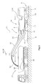
- Fig. 1 shows the example of a back-loader milling machine 1b, in which the transport vehicle 10 travels behind in reverse drive behind the milling machine.
- the transport vehicle 10 can also be moved in forward motion next to the milling machine 1.
- Fig. 2 shows a milling machine using the example of a front-end road milling machine 1a.
- the road construction machine 1 has a machine frame 2, which is supported by an existing example of crawler tracks or wheels chassis 4, which is connected via at least three height adjustment devices in the form of lifting columns 5 with the machine frame 2.
- four lifting columns 5 are provided, with which the machine frame 2 can be brought into a predetermined plane, which preferably runs parallel to the road surface 6, on which the crawler tracks of the chassis 4 are.
- Fig. 2 Road milling machine has a work roll 22 in the longitudinal direction of the milling machine 1a between the crawler tracks of the chassis 4.
- the work roll can be height-adjustable via the lifting frame 5 carrying the machine frame 2 or relative to the machine frame 2.
- the milling machines 1a, 1b may have crawler tracks and / or wheels.
- the milling machines 1a, 1b may have a single steerable axle as a steerable axle, or a steerable front axle in combination with at least one rear steerable wheel or track drive.
- a conveyor belt device with at least one conveyor belt 11, 12 for removal of the milled milled material at the front 7 or rear end 8 of the milling machine 1a, 1b may be arranged.
- the milled material milled by the work roll 22 is loaded onto the loading surface 15 of the transport vehicle 10 via a first stationary conveyor belt 11 of the conveyor belt device, which transfers the milled material 14 to a second pivotable conveyor belt 12. Due to the speed of the conveyor belt 12 of the conveyor belt device, the milled material 14 is not unloaded directly at the end of the conveyor belt 12, but the milled material follows a throw parabola, so that the point of impact 16 is located on the bed 15 at a distance from the free end 13 of the conveyor belt 12.
- the conveyor belt 12 can be pivoted from a central position to the left or to the right via piston-cylinder units 18 to dump the material to be milled 14 even when cornering or when tracked driving the transport vehicle 10 on the bed 15 or to the milling machine during conversion maneuvering to another place better. Furthermore, the operator of the milling machine 1a, 1b adjust the elevation angle of the conveyor belt 12 by means of a piston-cylinder unit 20. The elevation angle as well as the conveying speed of the conveyor belt 12, the parabolas of the milled material 14 and the position of the impact point 16 are influenced.
- the currently set elevation angle about a horizontal axis 21 or pivot angle about a vertical axis 23 and the current steering angle is reported to a detection and control system 24, which may further comprise at least one detector 26, the position of the loading surface 15 and / or of the transport direction last or single conveyor belt 12 of the conveyor belt device continuously detected.
- This detector 26 can either be arranged on the milling machine 1a, 1b at the end facing the conveyor belt 12 or at the free end 13 of the conveyor belt 12.
- the detection and control system 24 may be integrated into the operator-operated control 3 for the driving, steering and milling operation or at least connected to it, possibly also data on the driving speed, the distance covered and / or a detected steering angle the milling machine 1a, 1b and the conveying speed of the conveyor belt 12 to obtain.
- the controller 3 has a detection and control system 24 which detects the steering angle of the steering control for the chassis and automatically controls the pivot angle of the conveyor belt 12 in response to this parameter.
- the steering angle of the steering control and the distance traveled can be detected and controlled in dependence of these parameters, the pivot angle of the conveyor belt 12 automatically.
- the driving speed can be detected and the traveled distance can be calculated from the driving speed.
- Another possibility is to make a change in the swivel angle corresponding to the steering angle only when a minimum speed is exceeded.
- the pivot angle of the conveyor belt 12 thus follows the currently set or the average set over a certain distance traveled steering angle, which can be detected, for example, characterized in that the current steering angle z. B. is permanently detected at the wheels or crawler tracks of the front axle of the chassis or is taken directly from the steering control.
- the detection and control system 24 automatically control the pivoting angle of the conveyor belt 12 in such a way that the pivotable conveyor belt 12 assumes a pivoting angle calculated and predetermined by the control in each steering position during forward or reverse travel.
- the fictional trailer is provided with a wheel axle, which forms a center of rotation.
- the position of the center of rotation can be chosen freely, preferably in the range between one third and the entire length of the pivotable conveyor belt 12, or between one third and the entire length up to the point of impact 16 on a loading surface 15 of the transport vehicle.
- the detection and control system 24 can automatically control the pivoting angle of the conveyor belt 12 continuously such that the pivotable conveyor belt 12 in each steering position during forward or reverse travel assumes a pivot angle at which the end of the conveyor belt 12 or alternatively the point of impact 16 is guided on the loading surface 15 substantially along the center line 34 of the lane 32 which has already been driven over or is still to be driven over.
- the end of the conveyor belt 12 may also be guided along an equidistant to the center line 34 of the lane 32 already crossed or still to be driven over, namely when a transport vehicle 10 is moved next to the lane 32.
- the detection and control system 24 may have a distance measuring device 40, with which the distance to a following in the conveying direction of the conveyor belt 12 transport vehicle 10 is detectable. It can the detection and control system 24 for the driver of the transport vehicle 10 detectable, preferably visible start / stop signals generate.
- a programmable or teach-in readable distance range can be entered into the detection and control system 24 that is shorter than the maximum length of the loading surface 15 of the respective transport vehicle 10.
- the starting distance may depend on the measured distance. or stop signal are displayed.
- Fig. 3 shows a milling machine 1b according to Fig. 1 when cornering along a center line 34 of a lane 32.
- the conveyor belt 12 takes the position shown in dashed lines. It is understood that when starting from such a straight ahead cornering about a center of rotation 36 is initiated, the conveyor belt 12 would far out without a pivot angle control and on the one hand at a displacement of the milling machine with obstacles, such. As masts or traffic lights, could collide on the roadside, or could not unload in milling operation to a desired point of impact 16 on the bed of a transport vehicle 15 if the tilt angle would not be corrected.
- the conveyor belt 12 with a solid line shows the situation with an automatic swivel angle control, in which the free end of the conveyor belt 12 is guided along the center line 34.
- the calculation of the swivel angle by the controller 3, however, can also be such that the free end of the conveyor belt 12 can also follow an equidistant to the center line 34 of the lane 32, for example, to load a moving next to the lane 32 transport vehicle 10 can.
- the detection and control system 24 can also locate the variable position of the loading surface 15 of the transport vehicle 10 and the transport belt in the last or single conveyor belt 12 of the conveyor belt relative to the machine frame 2 and the positioning of the impact point 16 of the material to be milled 14 on the elevation angle and / or the conveying speed the conveyor belt device continuously and automatically control, so that the discarded Milling material 14 strikes at least within the loading area 15.
- the variable position of the loading area 15 of the transport vehicle 10 relative to the transport direction in the last or single conveyor belt 12 can be continuously located to perform the control.
- the detection and control system 24 can continuously detect the position of the loading area 15 and / or the last or single conveyor belt 12 in the transport direction with the aid of an image acquisition system 28 or a non-optical electronic location system, the data for determining the position of the loading area 15 in relation to the machine frame 2 or to the last or single conveyor belt 12 in the transport direction.
- the information of the image acquisition system 28 can be evaluated by known image analysis methods.
- An example of a non-optical electronic positioning system is a radio-frequency identification system (RFID), which additionally allows the possibility of identifying a specific loading area 15 of a specific transport vehicle 10.
- RFID radio-frequency identification system
- stationary RFID tags can be used on the transport vehicle 10, in particular on the loading surface 15.
- sensor nodes distributed in space are used as markers and the signal field strength, which is dependent on the distance, is measured.
- the distance measurement can be realized with the above measuring method, or with conventional measuring methods such. B. by means of ultrasound.
- the desired position data can be determined by a teach-in method by varying the positions of the vehicles 1a, 1b, 10 in accordance with realistic situations and storing the respectively required parameters, namely elevation angle and conveying speed of the conveyor belt 12. In the same way, a loading program can be created. It also variations of the control, the z. B. caused by cornering, are taken into account. The read by the reading data can also distinguish whether the transport vehicle 10 is left or right next to the milling track 32 or in the milling track 32 of the milling machine 1a, 1b.
Abstract
Description
Die Erfindung betrifft eine selbstfahrende Fräsmaschine nach dem Oberbegriff des Anspruchs 1, sowie ein Verfahren zum Lenken einer selbstfahrenden Fräsmaschine nach dem Oberbegriff des Anspruchs 8.The invention relates to a self-propelled milling machine according to the preamble of claim 1, and to a method for steering a self-propelled milling machine according to the preamble of
Die selbstfahrende Fräsmaschine, insbesondere Straßenfräse oder Surface Miner, weist einen Maschinenrahmen mit einer Längsachse, ein Fahrwerk mit Rädern oder Kettenlaufwerken, die den Maschinenrahmen tragen, sowie eine Steuerung für den Fahr-, Lenk- und Fräsbetrieb und eine höhenverstellbare Arbeitswalze auf. In Fahrtrichtung der Fräsmaschine vor oder hinter der Arbeitswalze ist ein schwenkbares letztes oder einziges Transportband vorgegebener Länge angeordnet, wobei das Transportband wenigstens um eine im Wesentlichen vertikal verlaufende erste Achse seitlich unter einem Schwenkwinkel verschwenkbar ist.The self-propelled milling machine, in particular road milling machine or surface miner, has a machine frame with a longitudinal axis, a chassis with wheels or crawler tracks that carry the machine frame, as well as a controller for the driving, steering and milling operation and a height-adjustable work roll on. In the direction of travel of the milling machine in front of or behind the work roll a pivotable last or single conveyor belt of predetermined length is arranged, wherein the conveyor belt at least about a substantially vertically extending first axis laterally pivotable at a pivot angle.
Die Fräsmaschine weist eine Steuerung für den Fahr- und Fräsbetrieb sowie eine Arbeitswalze zum Fräsen z. B. eines Straßenbelages auf. Vor oder hinter der Arbeitswalze - in Fahrtrichtung gesehen - befindet sich eine Transportbandeinrichtung mit mindestens einem Transportband. Das in Transportrichtung letzte oder einzige Transportband der Transportbandeinrichtung kann relativ zur Längsachse der Fräsmaschine seitlich unter einem vorgebbaren Schwenkwinkel nach links oder rechts verschwenkt werden und über einen vorgebbaren Höhenwinkel höhenverstellbar sein. Die Transportbandeinrichtung weist ein Abwurfende auf, an dem das Fräsgut aufgrund der Fördergeschwindigkeit und des Höhenwinkels über eine Flugbahn in Form einer Wurfparabel auf die Ladefläche eines Transportfahrzeugs abgeladen wird.The milling machine has a control for the driving and milling operation and a work roll for milling z. B. a road surface. Before or behind the work roll - seen in the direction of travel - there is a conveyor belt device with at least one conveyor belt. The last or only conveyor belt in the transport direction of the conveyor belt device can be pivoted laterally relative to the longitudinal axis of the milling machine at a predefinable pivoting angle to the left or right and over a predefinable elevation angle be height adjustable. The conveyor belt device has a discharge end on which the milled material is unloaded on the loading surface of a transport vehicle via a trajectory in the form of a trajectory parcel due to the conveying speed and the elevation angle.
Im praktischen Betrieb einer derartigen Fräsmaschine entstehen wegen des weit auskragenden Transportbandes Probleme bei der Lenkung der Fräsmaschine während des Betriebs und beim Versetzen der Fräsmaschine an einen anderen Ort.In practical operation of such a milling machine arise because of the far projecting conveyor belt problems in steering the milling machine during operation and when moving the milling machine to another location.
Beispielsweise wird bei einer Frontlader-Fräsmaschine das Fräsgut nach vorne auf das vorausfahrende Transportfahrzeug abgeworfen. Die Bedienungsperson für die Fräsmaschine muss dem Fahrzeugführer des Transportfahrzeuges signalisieren, wann sich das Transportfahrzeug weiter nach vorne bewegen soll. Dies führt zu Problemen, weil sich die Bedienungsperson im Grunde genommen auf den Fräsbetrieb konzentrieren muss und gleichzeitig eine Kollision mit dem vorausfahrenden Transportfahrzeug vermeiden muss.For example, in a front-end loader milling machine, the milled material is thrown forward onto the preceding transport vehicle. The operator for the milling machine must signal to the driver of the transport vehicle, when the transport vehicle should continue to move forward. This causes problems because the operator basically has to focus on the milling operation while avoiding a collision with the preceding transport vehicle.
Ein weiteres Problem besteht darin, dass die Bedienungsperson für die Fräsmaschine auch die Beladung der Ladefläche durch Verstellung des Schwenkwinkels, des Höhenwinkels und der Fördergeschwindigkeit des in Transportrichtung letzten oder einzigen Transportbandes der Transportbandeinrichtung übernehmen muss und dadurch von ihrer eigentlichen Aufgabe, den Fräsbetrieb durchzuführen, abgelenkt wird. Eine Korrektur des Schwenkwinkels kann beispielsweise bei einem Wechsel der Fahrtrichtung der Fräsmaschine notwendig sein.Another problem is that the operator for the milling machine and the loading of the loading surface by adjusting the pivot angle, the elevation angle and the conveying speed of the transport direction last or single conveyor belt of the conveyor belt device must take over and thereby deflected by their actual task to perform the milling operation becomes. A correction of the swivel angle may be necessary, for example, when changing the direction of travel of the milling machine.
Auch im Falle einer Hinterlader-Fräsmaschine bestehen Probleme bei der Koordination der Fräsmaschine mit dem Transportfahrzeug, zumal das Transportfahrzeug hinter der Fräsmaschine in Rückwärtsfahrt hinterherfahren muss. Für die Bedienungsperson der Fräsmaschine ergibt sich eine noch höhere Belastung, da sie einerseits den Fräsbetrieb in Vorwärtsfahrt steuern muss und andererseits die Beladung des Transportfahrzeugs in Fahrtrichtung hinter der Fräsmaschine beobachten muss, den Schwenkwinkel, den Höhenwinkel und/oder die Fördergeschwindigkeit der Transportbandeinrichtung steuern muss und dem Fahrzeugführer die notwendigen Informationen vermitteln muss.Even in the case of a back-loading milling machine, there are problems with the coordination of the milling machine with the transport vehicle, especially since the transport vehicle must drive behind the milling machine in reverse. For the operator of the milling machine results in an even greater burden, since on the one hand must control the milling operation in forward motion and on the other hand must observe the loading of the transport vehicle in the direction of travel behind the milling machine, the pivot angle, the elevation angle and / or the conveying speed of the conveyor belt device must control and provide the driver with the necessary information.
Beim Versetzen der selbstfahrenden Fräsmaschine an einen anderen Ort muss die Bedienungsperson der Fräsmaschine darauf achten, dass das weit auskragende Transportband, insbesondere bei engen Kurvenfahrten, nicht mit seitlichen Hindernissen, wie z. B. Masten, entlang einer Fahrspur kollidiert. Das Transportband kann länger als die eigentliche Fräsmaschine sein und hat üblicherweise eine Länge von ca. 5 m bis ca. 8 m.When moving the self-propelled milling machine to another location, the operator of the milling machine must make sure that the far projecting conveyor belt, especially in tight cornering, not with lateral obstacles such. As masts, collided along a lane. The conveyor belt can be longer than the actual milling machine and usually has a length of about 5 m to about 8 m.
Der Erfindung liegt daher die Aufgabe zugrunde, eine selbstfahrende Fräsmaschine, sowie ein Verfahren zum Lenken der Fräsmaschine zu schaffen, bei der die Bedienungsperson der Straßenfräsmaschine die Fräsmaschine im Fräsbetrieb oder beim Versetzen der Fräsmaschine fahren kann, ohne bei Kurvenfahrt ständig eine Korrektur des Schwenkwinkels des Transportbandes vornehmen zu müssen, und zwar unabhängig von der Fahrtrichtung der Fräsmaschine und der Anordnung des Transportbandes in Fahrtrichtung vor oder hinter der Fräsmaschine.The invention is therefore based on the object to provide a self-propelled milling machine, and a method for steering the milling machine, in which the operator of the road milling machine can drive the milling machine during milling or when moving the milling machine without constantly correcting the pivot angle of the conveyor belt when cornering to have to make, regardless of the direction of travel of the milling machine and the arrangement of the conveyor belt in the direction of travel in front of or behind the milling machine.
Zur Lösung dieser Aufgabe dienen die Merkmale der Ansprüche 1 bzw. 8.To solve this problem serve the features of
Die Erfindung sieht in vorteilhafter Weise vor, dass die Steuerung ein Erfassungs- und Steuerungssystem aufweist, das zumindest den Lenkeinschlag der Lenkungssteuerung für das Fahrwerk, oder zumindest den Lenkeinschlag der Lenkungssteuerung und die zurückgelegte Fahrstrecke oder die Fahrgeschwindigkeit erfasst, und in Abhängigkeit dieses mindestens einen Parameters den Schwenkwinkel des Transportbandes steuert. Aus dem Lenkeinschlag kann der aktuelle Krümmungsradius bei einer Kurvenfahrt ermittelt werden und aus dem aktuellen Krümmungsradius eine eventuell notwendige Anpassung des Schwenkwinkels.The invention advantageously provides that the controller has a detection and control system which detects at least the steering angle of the steering control for the chassis, or at least the steering angle of the steering control and the distance covered or the driving speed, and in dependence of this at least one parameter controls the tilt angle of the conveyor belt. From the steering angle of the current radius of curvature can be determined when cornering and from the current radius of curvature, a possibly necessary adjustment of the swivel angle.
Eine derartige automatische Steuerung des Schwenkwinkels ermöglicht es, dass sich die Bedienungsperson der Fräsmaschine auf den Fräsbetrieb und die Fahrt entlang einer vorgegebenen Frässpur konzentrieren kann bzw. die Fräsmaschine beliebig an einen anderen Ort versetzen kann, ohne dass eine ständige Korrektur des eingestellten Schwenkwinkels des Transportbandes erfolgen muss. Die Fräsmaschine kann auf diese Weise in Fahrtrichtung wie ein Fahrzeug mit einem gezogenen einachsigen Anhänger bewegt werden. Im Fräsbetrieb kann auf diese Weise auch erreicht werden, dass das Ende des Transportbandes oder die Abwurfstelle stets entlang der Mittellinie der gefahrenen Bahnkurve der Frässpur oder entlang einer Äquidistanten zur Mittellinie oder innerhalb einer Schleppkurve (Traktix) der selbstfahrenden Fräsmaschine gehalten wird. Die Bedienungsperson wird dadurch entlastet, dass sie sich insbesondere bei Kurvenfahrt nicht fortlaufend um eine Anpassung des Schwenkwinkels des Transportbandes kümmern muss.Such an automatic control of the swivel angle makes it possible for the operator of the milling machine to concentrate on the milling operation and the travel along a predetermined milling track or to move the milling machine to another location as desired without a constant correction of the set swivel angle of the conveyor belt got to. The milling machine can be moved in this way in the direction of travel as a vehicle with a pulled uniaxial trailer. In the milling operation can also be achieved in this way that the end of the conveyor belt or the discharge point always along the center line of the trajectory trajectory of the milling track or along an equidistant to the center line or within a traction curve (Traktix) of the self-propelled milling machine is held. The operator is relieved that they do not have to worry about an adjustment of the swing angle of the conveyor belt, especially when cornering.
Vorzugsweise ist vorgesehen, dass das Erfassungs- und Steuerungssystem den Schwenkwinkel des Transportbandes derart fortlaufend automatisch steuert, dass das schwenkbare Transportband in jeder Lenksituation bei Vorwärtsfahrt oder Rückwärtsfahrt einen Schwenkwinkel annimmt, der im Wesentlichen dem Schwenkwinkel der Längsachse eines, an die erste Achse angelenkten schwenkbaren fiktiven einachsigen Anhängers bei Vorwärtsfahrt entspricht.Preferably, it is provided that the detection and control system automatically controls the pivoting angle of the conveyor belt in such a way that the pivotable conveyor belt assumes a swivel angle in each steering position when driving forwards or backwards, which essentially corresponds to the swivel angle of the longitudinal axis of a pivotable fictitious linkage to the first axis uniaxial trailer when driving forward corresponds.
Die Steuerung kann somit für das Transportband ein Schwenkverhalten bei Kurvenfahrt, und zwar sowohl bei Vorwärtsfahrt als auch bei Rückwärtsfahrt, vorgeben, das dem eines fiktiven einachsigen Anhängers bei Vorwärtsfahrt entspricht. Somit kann die Bedienungsperson die Fräsmaschine auch rückwärts fahren, ohne dass sich das Transportband wie ein Anhänger bei Rückwärtsfahrt verhält.The controller can thus for the conveyor belt a swivel behavior when cornering, both forward and reverse, pretend that corresponds to that of a fictitious uniaxial trailer when driving forward. Thus, the operator can drive the milling machine also backwards, without the conveyor belt behaves like a trailer when reversing.
Nach einer Weiterbildung ist vorgesehen, dass das Erfassungs- und Steuerungssystem einen Schwenkwinkel für das schwenkbare Transportband vorgibt, der im Wesentlichen dem Schwenkwinkel der Längsachse eines an die erste Achse angelenkten schwenkbaren Anhängers bei Vorwärtsfahrt entspricht, wobei die Lage des Drehungszentrums um die Achse des fiktive Anhängers in der Längsrichtung wählbar ist.According to a further development, it is provided that the detection and control system specifies a pivoting angle for the pivotable conveyor belt, which substantially corresponds to the pivoting angle of the longitudinal axis of a hinged to the first axis pivotable trailer when moving forward, the position of the center of rotation about the axis of the fictitious trailer is selectable in the longitudinal direction.
Substituiert man gedanklich das Transportband durch einen Anhänger entsprechender Länge, so ist die Lage des Drehungszentrums des fiktiven Anhängers bei einem Anhänger mit einer einzigen Achse dort, wo die Radachse die Längsachse des Anhängers kreuzt. Mit Hilfe der Steuerung kann die Lage des Drehungszentrums vorgegeben werden, indem der Abstand des Drehungszentrums von der ersten vertikalen Achse in die Steuerung eingegeben wird.Substituted mentally the conveyor belt by a trailer of appropriate length, so is the location of the center of rotation of the fictitious trailer in a trailer with a single axis where the wheel axle crosses the longitudinal axis of the trailer. With the help of the controller, the position of the center of rotation can be specified by the distance of the center of rotation is entered from the first vertical axis in the controller.
Das Drehungszentrum kann einen Abstand von der ersten Achse im Bereich zwischen einem Drittel und der gesamten Länge des schwenkbaren Transportbandes oder der Länge bis zur Abwurfstelle aufweisen, vorzugsweise im Bereich zwischen 40 % und 60 % der gesamten Länge. Das Drehungszentrum auf einen Wert von ca. 50 % der Länge L zu setzen, ist vorteilhaft bei einem Versetzen der Fräsmaschine, da das seitliche Ausscheren des Transportbandes dann minimiert ist.The center of rotation may have a distance from the first axis in the range between one-third and the entire length of the pivotable conveyor belt or the length to the discharge point, preferably in the range between 40% and 60% of the total length. To set the center of rotation to a value of about 50% of the length L, is advantageous in a displacement of the milling machine, since the lateral shearing of the conveyor belt is then minimized.
Für den Fräsbetrieb könnte auch ein davon abweichender Wert verwendet werden. Es besteht auch die Möglichkeit, dass die Bedienungsperson die Lage des Drehungszentrums während der Fahrt verändert oder auch in Abhängigkeit der Art einer Kurvenfahrt (wie z. B. Kreisverkehr oder rechtwinkliges Abbiegen).For the milling operation also a deviating value could be used. There is also the possibility of the operator changing the position of the center of rotation while driving or depending on the type of cornering (such as roundabout or right-angle turning).
Die Steuerung kann den vorzugebenden Schwenkwinkel auch aus dem aktuell vorgegebenen Lenkwinkel (bzw. einem über eine bestimmte Fahrstrecke gemittelten) und den konstanten geometrischen Verhältnissen berechnen, indem der aktuell gefahrene Kurvenradius aus dem Lenkwinkel berechnet wird und aus dem Kurvenradius der Schwenkwinkel des Transportbandes (als Sekante) relativ zu der Längsachse der Fräsmaschine in der kreisförmigen aktuellen Fahrspur berechnet wird.The controller can also calculate the presettable swivel angle from the currently specified steering angle (or averaged over a certain distance) and the constant geometric conditions by calculating the current curvature radius from the steering angle and from the curve radius of the swing angle of the conveyor belt (as secant ) is calculated relative to the longitudinal axis of the milling machine in the circular current traffic lane.
Der Zusammenhang zwischen Kurvenradius r und Länge L des Transportbandes geht beispielsweise aus folgender Beziehung hervor:
- L=2 r sin (α/2), wobei α der Winkel zwischen den Radien ist, die auf die Enden der Länge L gerichtet sind. Der Schwenkwinkel beträgt dann α/2 in Relation zur Längsachse der Fräsmaschine. So ist eine Vorgabe eines Schwenkwinkels von α/2 mit einem Variationsbereich von bis zu ± 30 % möglich. Die Länge L kann sich auch über die Länge des Transportbandes hinaus auf die Länge des Transportbandes bis zur Auftreffstelle des Fräsgutes auf einer Ladefläche eines Transportfahrzeuges beziehen.
- Vorzugsweise ist vorgesehen, dass das Erfassungs- und Steuerungssystem den Schwenkwinkel des schwenkbaren Transportbandes derart fortlaufend automatisch steuert, dass das schwenkbare Transportband in jeder Lenksituation bei Vorwärtsfahrt oder Rückwärtsfahrt einen vorgegebenen Schwenkwinkel annimmt, bei dem das Ende des Transportbandes im Wesentlichen entlang der Mittellinie oder einer Äquidistante zur Mittellinie der bereits überfahrenen oder noch zu überfahrenden Fahrspur geführt ist.
- L = 2 r sin (α / 2), where α is the angle between the radii directed to the ends of the length L. The swivel angle is then α / 2 in relation to the longitudinal axis of the milling machine. Thus, a specification of a swivel angle of α / 2 with a variation range of up to ± 30% is possible. The length L may also relate to the length of the conveyor belt on the length of the conveyor belt to the point of impact of the material to be milled on a loading surface of a transport vehicle over the length of the conveyor belt.
- Preferably, it is provided that the detection and control system continuously controls the pivot angle of the pivotable conveyor belt in such a way that the pivotable conveyor belt in each steering situation Moving forward or reversing assumes a predetermined pivoting angle at which the end of the conveyor belt is guided substantially along the center line or an equidistant to the center line of the lane already overrun or still to be traveled over.
Bei einer besonders bevorzugten Weiterbildung ist vorgesehen, dass das Transportband um eine orthogonal zur ersten Achse verlaufende zweite Achse unter einem vorgegebenen Höhenwinkel verschwenkbar ist, wobei das Transportband das Fräsgut mit einer vorgegebenen Fördergeschwindigkeit auf eine Ladefläche eines Transportfahrzeugs abwirft, und das Erfassungs- und Steuerungssystem die Lage der Ladefläche und/oder des Transportbandes fortlaufend ortet, und eine fortlaufende Steuerung des Höhenwinkels des Transportbandes und/oder eine fortlaufende Geschwindigkeitssteuerung für die Fördergeschwindigkeit durchführt, um eine Auftreffstelle auf der Ladefläche stets innerhalb der Ladefläche oder zumindest entlang der Längsmittenebene der Ladefläche oder entlang der Mittellinie der bereits überfahrenen oder noch zu überfahrenden Fahrspur zu halten.In a particularly preferred embodiment, it is provided that the conveyor belt about a orthogonal to the first axis extending second axis is pivotable at a predetermined elevation angle, wherein the conveyor belt lays the milled material with a predetermined conveying speed on a loading area of a transport vehicle, and the detection and control system the Position of the cargo area and / or the conveyor belt locates continuously, and performs a continuous control of the angle of elevation of the conveyor belt and / or a continuous speed control for the conveying speed to a point of impact on the loading area always within the loading area or at least along the longitudinal center plane of the loading area or along the Center line of already overrun or still to be driven lane to keep.
Auf diese Weise ist ein automatischer Abladevorgang realisiert, der auch bei Kurvenfahrt für eine automatische Koordination des Abladevorgangs mit der Bewegung der Fräsmaschine und des Transportfahrzeugs sorgt. Dabei ist der Schwenkwinkel der Transportbandeinrichtung in Abhängigkeit vom Lenkwinkel der selbstfahrenden Fräsmaschine gesteuert.In this way, an automatic unloading process is realized, which ensures even during cornering for an automatic coordination of the unloading process with the movement of the milling machine and the transport vehicle. In this case, the pivot angle of the conveyor belt device is controlled in dependence on the steering angle of the self-propelled milling machine.
Vorzugsweise ist vorgesehen, dass das Erfassungs- und Steuerungssystem mindestens einen Detektor aufweist, der direkt oder indirekt den vorgegebenen Lenkeinschlag der Lenksteuerung für das Fahrwerk detektiert oder den Lenkeinschlag und die zurückgelegte Fahrstrecke oder Fahrgeschwindigkeit, sowie weitere Detektoren aufweist, die direkt oder indirekt den Schwenkwinkel und den Höhenwinkel detektieren.Preferably, it is provided that the detection and control system comprises at least one detector which detects directly or indirectly the predetermined steering angle of the steering control for the chassis or the steering angle and the traveled distance or speed, as well as other detectors that directly or indirectly the swivel angle and detect the elevation angle.
Bei einem vorteilhaften Ausführungsbeispiel ist vorgesehen, dass das Erfassungs- und Steuerungssystem eine Abstandsmesseinrichtung aufweist, mit der der Abstand zu einem in Förderrichtung des Transportbandes folgenden Transportfahrzeug detektierbar ist, wobei das Erfassungs- und Steuerungssystem für den Fahrzeugführer des Transportfahrzeugs erkennbare, vorzugsweise sichtbare Start-/ Stoppsignale für das Transportfahrzeug erzeugt.In an advantageous embodiment, it is provided that the detection and control system comprises a distance measuring device with which the distance to a following in the conveying direction of the conveyor belt transport vehicle is detectable, wherein the detection and control system for the Vehicle driver of the transport vehicle recognizable, preferably visible start / stop signals generated for the transport vehicle.
Dabei kann vorgehen sein, dass in das Erfassungs- und Steuerungssystem ein programmierbarer oder durch teach-in einlesbarer Abstandsbereich eingebbar ist, der kürzer ist als die maximale Länge der Ladefläche des jeweiligen Transportfahrzeugs, wobei in Abhängigkeit von dem gemessenen Abstand beim Verlassen des vorgegebenen Abstandsbereichs das Start- oder Stoppsignal ansteuerbar ist.It can proceed that in the detection and control system, a programmable or teach-in readable distance range is entered, which is shorter than the maximum length of the bed of the respective transport vehicle, depending on the measured distance when leaving the predetermined distance range the Start or stop signal can be controlled.
Fortbewegungs-Steuerungssignale für das Transportfahrzeug sind grundsätzlich in der
Zur Lösung der Aufgabe dienen auch die Merkmale des Anspruchs 8.To solve the problem, the features of
Das erfindungsgemäße Verfahren betrifft ein Verfahren zum Lenken einer selbstfahrenden Fräsmaschine, insbesondere Straßenfräsmaschine oder Surface Miner, entlang einer vorgegebenen Fahrspur, die für den Fahr-, Lenk-, und Fräsbetrieb eine Steuerung aufweist. Die Fräsmaschine mit einer Längsachse wird von einem lenkbaren Fahrwerk mit Rädern oder Kettenlaufwerken getragen, wobei das von einer Arbeitswalze abgearbeitete Fräsgut im Fräsbetrieb mit einer in Fahrtrichtung der Fräsmaschine vor oder hinter der Fräsmaschine angeordneten Transportband abtransportiert wird. Das letzte oder einzige Transportband kann seitlich verschwenkt werden. Zumindest der Lenkeinschlag der Lenkungssteuerung für das Fahrwerk, oder zumindest der Lenkeinschlag der Lenkungssteuerung und die zurückgelegte Fahrstrecke oder die Fahrgeschwindigkeit werden erfasst und in Abhängigkeit dieses mindestens einen Parameters wird der Schwenkwinkel des Transportbandes gesteuert.The inventive method relates to a method for steering a self-propelled milling machine, in particular road milling machine or surface miner along a predetermined lane, which has a control for the driving, steering, and milling operation. The milling machine with a longitudinal axis is carried by a steerable chassis with wheels or crawler tracks, wherein the processed from a work roll milled material is removed in milling with a arranged in the direction of travel of the milling machine in front of or behind the milling machine conveyor belt. The last or only conveyor belt can be swiveled laterally. At least the steering angle of the steering control for the chassis, or at least the steering angle of the steering control and the distance traveled or the vehicle speed are detected and depending on this at least one parameter, the pivot angle of the conveyor belt is controlled.
Dabei kann der Schwenkwinkel des Transportbandes derart fortlaufend automatisch gesteuert werden, dass das schwenkbare Transportband in jeder Lenksituation bei Vorwärtsfahrt oder Rückwärtsfahrt einen vorgegebenen Schwenkwinkel annimmt, der im Wesentlichen dem Schwenkwinkel der Längsachse eines, um die erste Achse schwenkbaren fiktiven Anhängers bei Vorwärtsfahrt entspricht. Vorzugsweise ist vorgesehen, dass der Schwenkwinkel für das schwenkbare Transportband derart fortlaufend automatisch gesteuert wird, dass der vorgegebene Schwenkwinkel im Wesentlichen dem Schwenkwinkel der Längsachse eines, um die erste Achse schwenkbaren fiktiven Anhängers bei Vorwärtsfahrt entspricht, wobei die Lage des Drehungszentrums des Anhängers entlang der Längsachse des Transportbandes frei ausgewählt werden kann, um einen aktuellen Schwenkwinkel zu berechnen und einzustellen.In this case, the pivoting angle of the conveyor belt can be continuously controlled in such a way that the pivotable conveyor belt assumes a predetermined pivot angle in each steering position when driving forwards or backwards, which essentially corresponds to the pivoting angle of the longitudinal axis of a fictitious trailer pivoting about the first axis when driving forward. Preferably, it is provided that the pivoting angle for the pivotable conveyor belt is continuously controlled such that the predetermined pivoting angle substantially corresponds to the pivoting angle of the longitudinal axis of a pivotable about the first axis fictitious trailer when driving forward, the position of the center of rotation of the trailer along the longitudinal axis of the conveyor belt can be freely selected to calculate and set a current swing angle.
Es kann vorgesehen sein, dass die Ladefläche geortet wird und der Höhenwinkel und/oder die Fördergeschwindigkeit des Transportbandes derart geregelt werden, dass die Auftreffstelle auf der Ladefläche auch bei Kurvenfahrt entlang der Längsmittelebene der Ladefläche oder auf der Mittellinie der Fahrspur gehalten wird.It can be provided that the loading area is located and the elevation angle and / or the conveying speed of the conveyor belt are controlled such that the point of impact is held on the truck bed even when cornering along the median longitudinal plane of the truck bed or on the center line of the lane.
Weitere vorteilhafte Merkmale sind der Beschreibung zu entnehmen.Further advantageous features are described in the description.
Im Folgenden werden unter Bezugnahme auf die Zeichnungen Ausführungsbeispiele der Erfindung näher erläutert.In the following, embodiments of the invention will be explained in more detail with reference to the drawings.
Es zeigen:
- Fig. 1
- eine Hinterlader-Straßenfräsmaschine,
- Fig. 2
- eine Frontlader-Straßenfräsmaschine, und
- Fig. 3
- eine schematische Darstellung der Schwenkwinkelsteuerung in Abhängigkeit von dem Lenkwinkel bei einer Straßenfräsmaschine gemäß
Fig. 1 .
- Fig. 1
- a backloader road milling machine,
- Fig. 2
- a front loader road milling machine, and
- Fig. 3
- a schematic representation of the swivel angle control in dependence on the steering angle in a road milling machine according to
Fig. 1 ,
Die nachfolgende Beschreibung bezieht sich auf selbstfahrende Fräsmaschinen, und zwar insbesondere auf Straßenfräsmaschinen, und auch auf Surface Miner.The following description refers to self-propelled milling machines, especially on road milling machines, and also to surface miners.
Sofern seitlich neben der Fräsmaschine 1a, 1b ausreichend Platz zur Verfügung steht, kann das Transportfahrzeug 10 auch in Vorwärtsfahrt neben der Fräsmaschine 1 bewegt werden.If there is sufficient space available laterally next to the
Die in
Die Arbeitswalze kann über die den Maschinenrahmen 2 tragenden Hubsäulen 5 oder relativ zu dem Maschinenrahmen 2 höhenverstellbar sein.The work roll can be height-adjustable via the
Die Fräsmaschinen 1a, 1b können Kettenlaufwerke und/oder Räder aufweisen.The
Andere Bauformen einer Fräsmaschine 1b können die Arbeitswalze 22 beispielsweise auch in Höhe der hinteren Kettenlaufwerke oder Räder des Fahrwerks 4 aufweisen, wie in der
Die Fräsmaschinen 1a, 1b können eine einzige lenkbare Achse als eine lenkbare Achse aufweisen, oder eine lenkbare Vorderachse in Kombination mit mindestens einem hinteren lenkbaren Rad- oder Kettenlaufwerk.The
Ebenso kann eine Transportbandeinrichtung mit mindestens einem Transportband 11, 12 zum Abtransport des abgefrästen Fräsgutes am vorderen 7 oder hinteren Ende 8 der Fräsmaschine 1a, 1b angeordnet sein.Likewise, a conveyor belt device with at least one
Die Fahrtrichtungen der jeweiligen Fahrzeuge sind in den
Bei dem Ausführungsbeispiel der
Der aktuell eingestellte Höhenwinkel um eine horizontale Achse 21 bzw. Schwenkwinkel um eine vertikale Achse 23 sowie der aktuelle Lenkwinkel wird an ein Erfassungs- und Steuerungssystem 24 gemeldet, das des Weiteren mindestens einen Detektor 26 aufweisen kann, der die Lage der Ladefläche 15 und/oder des in Transportrichtung letzten oder einzigen Transportbandes 12 der Transportbandeinrichtung fortlaufend detektiert. Dieser Detektor 26 kann entweder an der Fräsmaschine 1a, 1b an dem dem Transportband 12 zugewandten Ende oder an dem freien Ende 13 des Transportbandes 12 angeordnet sein.The currently set elevation angle about a
Das Erfassungs- und Steuerungssystem 24 kann in die von der Bedienungsperson betätigte Steuerung 3 für den Fahr-, Lenk- und Fräsbetrieb integriert sein oder mit dieser zumindest verbunden sein, um ggf. auch Daten über die Fahrgeschwindigkeit, die zurückgelegte Fahrstrecke und/oder einen detektierten Lenkwinkel der Fräsmaschine 1a, 1b und die Fördergeschwindigkeit des Transportbandes 12 zu erhalten.The detection and control system 24 may be integrated into the operator-operated control 3 for the driving, steering and milling operation or at least connected to it, possibly also data on the driving speed, the distance covered and / or a detected steering angle the
Die Steuerung 3 weist ein Erfassungs- und Steuerungssystem 24 auf, das den Lenkeinschlag der Lenksteuerung für das Fahrwerk erfasst und in Abhängigkeit dieses Parameters den Schwenkwinkel des Transportbandes 12 automatisch steuert.The controller 3 has a detection and control system 24 which detects the steering angle of the steering control for the chassis and automatically controls the pivot angle of the
Alternativ können der Lenkeinschlag der Lenkungssteuerung und die zurückgelegte Fahrstrecke erfasst werden und in Abhängigkeit dieser Parameter der Schwenkwinkel des Transportbandes 12 automatisch gesteuert werden. Durch das zusätzliche Erfassen der zurückgelegten Fahrstrecke lassen sich zu starke Änderungen des Schwenkwinkels bei schnellen Änderungen des Lenkwinkels vermeiden. Es kann auch alternativ die Fahrgeschwindigkeit detektiert werden und die zurückgelegte Fahrstrecke aus der Fahrgeschwindigkeit berechnet werden.Alternatively, the steering angle of the steering control and the distance traveled can be detected and controlled in dependence of these parameters, the pivot angle of the
Eine weitere Möglichkeit besteht darin, eine Änderung des Schwenkwinkels entsprechend dem Lenkwinkel erst dann vorzunehmen, wenn eine Mindestgeschwindigkeit überschritten ist.Another possibility is to make a change in the swivel angle corresponding to the steering angle only when a minimum speed is exceeded.
Der Schwenkwinkel des Transportbandes 12 folgt demzufolge dem aktuell eingestellten oder dem durchschnittlich über eine bestimmte zurückgelegte Fahrstrecke eingestellten Lenkeinschlag, der beispielsweise dadurch erfasst werden kann, dass der aktuelle Lenkwinkel z. B. an den Rädern oder Kettenlaufwerken der vorderen Achse des Fahrwerks permanent erfasst wird oder direkt von der Lenksteuerung übernommen wird.The pivot angle of the
Dabei kann das Erfassungs- und Steuerungssystem 24 den Schwenkwinkel des Transportbandes 12 derart fortlaufend automatisch steuern, dass das schwenkbare Transportband 12 in jeder Lenksituation bei Vorwärts- oder Rückwärtsfahrt einen von der Steuerung berechneten und vorgegebenen Schwenkwinkel annimmt.In this case, the detection and control system 24 automatically control the pivoting angle of the
Die Folge davon ist, dass die Bedienungsperson der Fräsmaschine sich nicht darum kümmern muss, den Schwenkwinkel des Transportbandes bei Kurvenfahrt, sei es im Fräsbetrieb oder beim Versetzen der Maschine an einen anderen Ort, ständig zu beobachten und bei Bedarf anzupassen. Vielmehr wird durch die automatische Steuerung des Schwenkwinkels zuverlässig erreicht, dass sich das Transportband 12 im Wesentlichen wie ein nachlaufender Anhänger an der Fräsmaschine bei Vorwärtsfahrt verhält. Dabei ist angenommen, dass ein solcher fiktiver Anhänger um die erste Schwenkachse 23 verschwenkbar ist und der Schwenkwinkel, den der Anhänger bei einer Kurvenfahrt in Vorwärtsrichtung annehmen würde, wird sowohl für die Vorwärtsfahrt als auch für die Rückwärtsfahrt als einzustellender vorgegebener Schwenkwinkel für das Transportband 12 verwendet.The consequence of this is that the operator of the milling machine does not have to worry about constantly observing the swivel angle of the conveyor belt when cornering, be it while milling or when moving the machine to another location, and adjust it as needed. Rather, it is reliably achieved by the automatic control of the swivel angle that the
Der fiktive Anhänger ist mit einer Radachse versehen, die ein Drehungszentrum bildet. Zur Berechnung des Schwenkwinkels durch die Steuerung 3 bzw. das Erfassungs- und Steuerungssystem 24 kann die Lage des Drehungszentrums frei gewählt werden, und zwar vorzugsweise im Bereich zwischen einem Drittel und der gesamten Länge des schwenkbaren Transportbandes 12, oder zwischen einem Drittel und der gesamten Länge bis zur Auftreffstelle 16 auf einer Ladefläche 15 des Transportfahrzeugs. Bei einem bevorzugten Ausführungsbeispiel kann das Erfassungs- und Steuerungssystem 24 den Schwenkwinkel des Transportbandes 12 derart fortlaufend automatisch steuern, dass das schwenkbare Transportband 12 in jeder Lenksituation bei Vorwärts- oder Rückwärtsfahrt einen Schwenkwinkel annimmt, bei dem das Ende des Transportbandes 12 oder auch alternativ die Auftreffstelle 16 auf der Ladefläche 15 im Wesentlichen entlang der Mittellinie 34 der bereits überfahrenen oder noch zu überfahrenden Fahrspur 32 geführt ist.The fictional trailer is provided with a wheel axle, which forms a center of rotation. For calculating the pivot angle by the controller 3 and the detection and control system 24, the position of the center of rotation can be chosen freely, preferably in the range between one third and the entire length of the
Nach einer weiteren Alternative kann das Ende des Transportbandes 12 auch entlang einer Äquidistanten zur Mittellinie 34 der bereits überfahrenen oder noch zu überfahrenden Fahrspur 32 geführt sein, nämlich dann, wenn ein Transportfahrzeug 10 neben der Fahrspur 32 bewegt wird.According to a further alternative, the end of the
Desweiteren kann das Erfassungs- und Steuerungssystem 24 eine Abstandmesseinrichtung 40 aufweisen, mit der der Abstand zu einem in Förderrichtung des Transportbandes 12 folgenden Transportfahrzeug 10 detektierbar ist. Dabei kann das Erfassungs- und Steuerungssystem 24 für den Fahrzeugführer des Transportfahrzeugs 10 erkennbare, vorzugsweise sichtbare Start-/Stoppsignale erzeugen.Furthermore, the detection and control system 24 may have a
In das Erfassung- und Steuerungssystem 24 kann ein programmierbarer oder durch teach-in einlesbarer Abstandsbereich eingebbar sein, der kürzer ist als die maximale Länge der Ladefläche 15 des jeweiligen Transportfahrzeugs 10. Beim Verlassen des vorgegebenen Abstandsbereichs kann in Abhängigkeit von dem gemessenen Abstand das Start- oder Stoppsignal angezeigt werden.A programmable or teach-in readable distance range can be entered into the detection and control system 24 that is shorter than the maximum length of the
Das Transportband 12 mit ausgezogener Linie zeigt die Situation bei einer automatischen Schwenkwinkelsteuerung, bei der das freie Ende des Transportbandes 12 entlang der Mittellinie 34 geführt ist. Die Berechnung des Schwenkwinkels durch die Steuerung 3 kann allerdings auch so erfolgen, dass das freie Ende des Transportbandes 12 auch einer Äquidistanten zur Mittellinie 34 der Fahrspur 32 folgen kann, um beispielsweise ein neben der Fahrspur 32 fahrendes Transportfahrzeug 10 beladen zu können.The
Das Erfassung- und Steuerungssystem 24 kann auch die veränderliche Lage der Ladefläche 15 des Transportfahrzeugs 10 und des in Transportrichtung letzten oder einzigen Transportbandes 12 der Transportbandeinrichtung relativ zum Maschinenrahmen 2 orten und die Positionierung der Auftreffstelle 16 des Fräsgutes 14 über den Höhenwinkel und/oder die Fördergeschwindigkeit der Transportbandeinrichtung fortlaufend und automatisch steuern, so dass das abgeworfene Fräsgut 14 zumindest innerhalb der Ladefläche 15 auftrifft. Alternativ kann auch die veränderliche Lage der Ladefläche 15 des Transportfahrzeugs 10 relativ zu dem in Transportrichtung letzten oder einzigen Transportband 12 fortlaufend geortet werden, um die Steuerung durchzuführen.The detection and control system 24 can also locate the variable position of the
Das Erfassungs- und Steuerungssystem 24 kann die Lage der Ladefläche 15 und/oder des in Transportrichtung letzten oder einzigen Transportbandes 12 fortlaufend mit Hilfe eines Bildaufnahmesystems 28 oder eines nicht optischen elektronischen Ortungssystems erfassen, das Daten zur Lagebestimmung der Ladefläche 15 in Relation zu dem Maschinenrahmen 2 oder zu dem in Transportrichtung letzten oder einzigen Transportbandes 12 liefert. Die Informationen des Bildaufnahmesystems 28 kann durch für sich bekannte Bildanalysemethoden ausgewertet werden. Ein Beispiel für ein nicht optisches elektronisches Ortungssystems ist ein Radiofrequenz-Identifikationssystem (RFID), das zusätzlich noch die Möglichkeit der Identifikation einer bestimmten Ladefläche 15 eines bestimmten Transportfahrzeugs 10 ermöglicht.The detection and control system 24 can continuously detect the position of the
Bei der Lokalisierung der Ladefläche 15 mit RFID können stationäre RFID-Tags an dem Transportfahrzeug 10 insbesondere an der Ladefläche 15 verwendet werden.When localizing the
Bei einer Lokalisierung mit Bluetooth-Sensorknoten als weiteres nicht optisches Lokalisierungsverfahren werden im Raum verteilte Sensorknoten als Markierungen verwendet und die Signalfeldstärke, die abhängig von der Entfernung ist, gemessen.When localized with Bluetooth sensor nodes as another non-optical localization method, sensor nodes distributed in space are used as markers and the signal field strength, which is dependent on the distance, is measured.
Selbstverständlich besteht auch die Möglichkeit, unterschiedliche Lokalisierungsverfahren in Kombination zu verwenden.Of course, it is also possible to use different localization methods in combination.
Generell kann mit optischen und quasi-optischen (Funk-) Messmethoden für Länge und Winkel, sowie mit verschiedenen Zeitmessverfahren für Zeitdifferenzen und Laufzeitdifferenzen gearbeitet werden.In general, it is possible to work with optical and quasi-optical (radio) measuring methods for length and angle, as well as with different timing methods for time differences and propagation time differences.
Auch die Abstandsmessung kann mit obigen Messverfahren realisiert werden, oder aber mit konventionellen Messverfahren, wie z. B. mittels Ultraschall.The distance measurement can be realized with the above measuring method, or with conventional measuring methods such. B. by means of ultrasound.
Die Soll-Lagedaten können durch ein Teach-in-Verfahren ermittelt werden, indem die Positionen der Fahrzeuge 1a, 1b, 10 entsprechend realistischen Situationen variiert werden und die jeweils hierfür notwendigen Parameter, nämlich Höhenwinkel und Fördergeschwindigkeit des Transportbandes 12 gespeichert werden. In gleicher Weise kann auch ein Beladungsprogramm erstellt werden. Dabei können auch Variationen der Steuerung, die z. B. durch Kurvenfahrt entstehen, berücksichtigt werden. Die durch den Lesevorgang eingelesenen Daten können dabei auch unterscheiden, ob das Transportfahrzeug 10 links oder rechts neben der Frässpur 32 fährt oder in der Frässpur 32 der Fräsmaschine 1a, 1b.The desired position data can be determined by a teach-in method by varying the positions of the
Claims (15)
dadurch gekennzeichnet,dass
die Steuerung (3) ein Erfassungs- und Steuerungssystem (24) aufweist,
das zumindest den Lenkeinschlag der Lenkungssteuerung für das Fahrwerk, oder zumindest den Lenkeinschlag der Lenkungssteuerung und die zurückgelegte Fahrstrecke oder die Fahrgeschwindigkeit erfasst und in Abhängigkeit dieses mindestens einen Parameters den Schwenkwinkel des Transportbandes (12) steuert.
characterized in that
the controller (3) has a detection and control system (24),
which detects at least the steering angle of the steering control for the chassis, or at least the steering angle of the steering control and the distance covered or the driving speed and controls the pivot angle of the conveyor belt (12) in dependence on this at least one parameter.
wobei das Transportband (12) das Fräsgut (14) mit einer vorgegebenen Fördergeschwindigkeit auf eine Ladefläche (15) eines Transportfahrzeugs (10) abwirft, und
das Erfassungs- und Steuerungssystem (24) die Lage der Ladefläche (15) und/oder des Transportbandes (12) fortlaufend ortet, und eine fortlaufende Steuerung des Höhenwinkels des Transportbandes (12) und/oder eine fortlaufende Geschwindigkeitssteuerung für die Fördergeschwindigkeit durchführt, um eine Auftreffstelle (16) auf der Ladefläche (15) stets innerhalb der Ladefläche (15) oder zumindest entlang der Längsmittenebene der Ladefläche (15) oder entlang der Mittellinie (34) in der Mitte der bereits überfahrenen oder noch zu überfahrenden Fahrspur (32) zu halten.Device according to one of claims 1 to 5, characterized in that the conveyor belt (12) about a orthogonal to the first axis (23) extending second axis (21) is pivotable at a predetermined elevation angle,
wherein the conveyor belt (12) drops the milled material (14) at a predetermined conveying speed onto a loading surface (15) of a transport vehicle (10), and
the detection and control system (24) continuously locates the position of the bed (15) and / or the conveyor (12), and continuous control of the elevation angle of the conveyor (12) and / or a continuous speed control for the conveyor speed is carried out to an impact point (16) on the loading surface (15) always within the loading area (15) or at least along the longitudinal center plane of the loading area (15) or along the center line (34) in the middle of the already traveled or still to be traveled lane ( 32).
dadurch gekennzeichnet, dass
zumindest der Lenkeinschlag der Lenkungssteuerung für das Fahrwerk, oder zumindest der Lenkeinschlag der Lenkungssteuerung und die zurückgelegte Fahrstrecke oder Fahrgeschwindigkeit erfasst werden und in Abhängigkeit dieses mindestens einen Parameters der Schwenkwinkel des Transportbandes (12) gesteuert wird.
characterized in that
at least the steering angle of the steering control for the chassis, or at least the steering angle of the steering control and the traveled distance or travel speed are detected and in dependence of this at least one parameter, the pivot angle of the conveyor belt (12) is controlled.
Applications Claiming Priority (1)
| Application Number | Priority Date | Filing Date | Title |
|---|---|---|---|
| DE102012215005.6A DE102012215005A1 (en) | 2012-08-23 | 2012-08-23 | Self-propelled milling machine, as well as method for steering a self-propelled milling machine |
Publications (2)
| Publication Number | Publication Date |
|---|---|
| EP2700748A1 true EP2700748A1 (en) | 2014-02-26 |
| EP2700748B1 EP2700748B1 (en) | 2016-03-16 |
Family
ID=49028941
Family Applications (1)
| Application Number | Title | Priority Date | Filing Date |
|---|---|---|---|
| EP13181254.7A Active EP2700748B1 (en) | 2012-08-23 | 2013-08-21 | Self-propelled milling machine, and method for steering a self-propelled milling machine |
Country Status (4)
| Country | Link |
|---|---|
| US (3) | US9234319B2 (en) |
| EP (1) | EP2700748B1 (en) |
| CN (2) | CN203654144U (en) |
| DE (1) | DE102012215005A1 (en) |
Cited By (6)
| Publication number | Priority date | Publication date | Assignee | Title |
|---|---|---|---|---|
| EP2987911A1 (en) * | 2014-08-22 | 2016-02-24 | Wirtgen GmbH | Self-propelled milling machine, and method for unloading milled goods |
| EP2987910A1 (en) * | 2014-08-21 | 2016-02-24 | Wirtgen GmbH | Self-propelled milling machine, and method for unloading milled goods |
| CN105386399A (en) * | 2015-10-13 | 2016-03-09 | 长安大学 | Road milling machine and milling flatness auxiliary control method |
| DE102016222589A1 (en) | 2016-11-16 | 2018-05-17 | Wirtgen Gmbh | Self-propelled milling machine, as well as method for controlling a self-propelled milling machine |
| US10927515B2 (en) | 2017-11-22 | 2021-02-23 | Wirtgen Gmbh | Self-propelled milling machine, method for automatically loading a means of transport with milling material, as well as road or ground working unit |
| US11318941B2 (en) | 2019-02-19 | 2022-05-03 | Wirtgen Gmbh | Working combination encompassing an earth working machine and a further vehicle, and an automatic spacing monitoring system |
Families Citing this family (19)
| Publication number | Priority date | Publication date | Assignee | Title |
|---|---|---|---|---|
| DE102009041842A1 (en) | 2009-09-18 | 2011-09-01 | Wirtgen Gmbh | Self-propelled road milling machine |
| DE102013009361B4 (en) * | 2013-06-04 | 2018-07-12 | Bomag Gmbh | Floor milling machine with an attached conveyor belt control, attached conveyor belt control for a ground milling machine and method for controlling a crop conveyor belt of a ground milling machine |
| FR3010805A1 (en) * | 2013-09-13 | 2015-03-20 | Airbus Operations Sas | METHOD AND DEVICE FOR AIDING THE CONTROL OF AN AIRCRAFT ON A PARABOLIC FLIGHT TO GENERATE AN IMPERATIVE IN THE AIRCRAFT. |
| DE102014216763B4 (en) | 2014-08-22 | 2018-07-26 | Wirtgen Gmbh | Self-propelled milling machine, as well as method for unloading milled material |
| US9464391B2 (en) * | 2014-08-29 | 2016-10-11 | Caterpillar Paving Products Inc. | Cold planer having independently controlled conveyors |
| US10380529B2 (en) * | 2015-08-17 | 2019-08-13 | Caterpillar Paving Products Inc. | Cold planer material transport management system |
| US20170130405A1 (en) | 2015-11-05 | 2017-05-11 | Caterpillar Paving Products Inc. | Truck position control system for milling operations |
| CN108473260B (en) | 2016-01-21 | 2022-08-12 | 维特根有限公司 | System comprising a construction machine, a transport vehicle with a loading space and an image recording device, and method for displaying an image stream during loading or unloading of a transport vehicle |
| US10927513B2 (en) | 2016-11-11 | 2021-02-23 | Wirtgen Gmbh | System and method for the tracking of milling material |
| DE102016222145A1 (en) | 2016-11-11 | 2018-05-17 | Wirtgen Gmbh | System and method for tracking milled material |
| DE102016223454A1 (en) | 2016-11-25 | 2018-05-30 | Wirtgen Gmbh | System and method for tracking milled material |
| CN108278981A (en) * | 2018-02-11 | 2018-07-13 | 北京主线科技有限公司 | Detect the device and its detection method of unmanned trailer axle drift angle |
| CN108221610A (en) * | 2018-03-14 | 2018-06-29 | 徐州徐工筑路机械有限公司 | A kind of milling machine automatically transporting materials system of view-based access control model identification |
| DE102018119962A1 (en) * | 2018-08-16 | 2020-02-20 | Wirtgen Gmbh | Self-propelled construction machine and method for controlling a self-propelled construction machine |
| US10982397B2 (en) * | 2019-06-12 | 2021-04-20 | Caterpillar Paving Products Inc. | Milling rotor |
| CN111926666A (en) * | 2020-07-02 | 2020-11-13 | 丁丽丽 | High-efficient patching device of bituminous paving for municipal works |
| CN112065384B (en) * | 2020-09-02 | 2022-05-17 | 山东中煤工矿物资集团有限公司 | Carrier equipment with excavation function |
| US20220267967A1 (en) | 2021-02-23 | 2022-08-25 | Ligchine International Corporation | Swing Boom Concrete Screeding Apparatus |
| CN114455249A (en) * | 2022-01-05 | 2022-05-10 | 中国电建集团华东勘测设计研究院有限公司 | Arrangement method of long-distance large-traffic-capacity space curve belt conveyor |
Citations (5)
| Publication number | Priority date | Publication date | Assignee | Title |
|---|---|---|---|---|
| DE202007005756U1 (en) * | 2007-04-19 | 2008-08-28 | Wirtgen Gmbh | Self-propelled construction machine |
| EP2100495A1 (en) * | 2008-03-13 | 2009-09-16 | CLAAS Selbstfahrende Erntemaschinen GmbH | Agricultural harvester with a transfer device |
| DE102009041842A1 (en) | 2009-09-18 | 2011-09-01 | Wirtgen Gmbh | Self-propelled road milling machine |
| EP2452551A2 (en) * | 2010-11-12 | 2012-05-16 | Deere & Company | Control assembly for controlling the transfer of harvested agricultural goods from a harvester to a transport vehicle |
| EP2573267A1 (en) * | 2011-09-22 | 2013-03-27 | BOMAG GmbH | Maintenance train with a milling device and a transport device and a sensor device for distance monitoring, milling device having a sensor device and method for distance monitoring in a maintenance train |
Family Cites Families (30)
| Publication number | Priority date | Publication date | Assignee | Title |
|---|---|---|---|---|
| US3608968A (en) | 1969-04-03 | 1971-09-28 | Christensen Diamond Prod Co | Pavement cutting and water and cutting pickup apparatus |
| US4376609A (en) * | 1980-03-31 | 1983-03-15 | Sperry Corporation | Automatic spout control for agricultural machines |
| DD155157A1 (en) | 1980-12-09 | 1982-05-19 | Bernd Kaempfe | POSITIONING DEVICE, IN PARTICULAR BETWEEN RE-ESTATE MACHINERY AND TRANSPORT VEHICLES |
| US4863009A (en) | 1988-11-14 | 1989-09-05 | Alberta Energy Company Ltd. | Control system for an endless belt conveyor train |
| DE4403893A1 (en) | 1994-02-08 | 1995-08-10 | Claas Ohg | Device for the automatic filling of loading containers with a stream of material |
| DE19628420C2 (en) | 1996-07-15 | 1999-07-29 | Krupp Foerdertechnik Gmbh | Process for material degradation using a bucket wheel excavator |
| WO1999052068A1 (en) | 1998-04-03 | 1999-10-14 | Koninklijke Philips Electronics N.V. | Image processing method and system involving contour detection steps |
| DE19848127A1 (en) * | 1998-10-19 | 2000-04-20 | Claas Selbstfahr Erntemasch | Device for controlling a transfer device |
| US6682416B2 (en) * | 2000-12-23 | 2004-01-27 | Claas Selbstfahrende Erntemaschinen Gmbh | Automatic adjustment of a transfer device on an agricultural harvesting machine |
| DE10203732A1 (en) | 2002-01-30 | 2003-08-21 | Wirtgen Gmbh | Construction machinery |
| US6943824B2 (en) * | 2002-03-13 | 2005-09-13 | Deere & Company | Image processing spout control system |
| DE10223819B4 (en) * | 2002-05-28 | 2005-05-12 | Wirtgen Gmbh | Milling machine for processing soil surfaces, and method for disposing of generated during milling dust and vapors on a milling machine |
| CN1209530C (en) * | 2003-05-16 | 2005-07-06 | 长沙中联重工科技发展股份有限公司 | Method and device for realizing adaptive control of discharging speed of milling and planning machine |
| DE10357074B3 (en) * | 2003-12-04 | 2005-05-19 | Wirtgen Gmbh | Self-propelled road surfacing machine with direct mechanical drive of working roller from drive take-off shaft of internal combustion engine |
| CN2697144Y (en) * | 2004-02-10 | 2005-05-04 | 三一重工股份有限公司 | Television monitor controller for transfer vehicle |
| DE102004007716B3 (en) * | 2004-02-16 | 2005-06-16 | Wirtgen Gmbh | Road construction asphalt milling machine has dust suction unit located well away from rotating milling tool |
| DE102004011789A1 (en) | 2004-03-09 | 2005-09-29 | Claas Selbstfahrende Erntemaschinen Gmbh | Device for detecting a loading wagon |
| US20060045621A1 (en) | 2004-08-27 | 2006-03-02 | Caterpillar Paving Products Inc. | Asphalt-removing work machine having a storage bin |
| DE102005035480A1 (en) | 2005-07-26 | 2007-02-01 | Cft Gmbh Compact Filter Technic | Milling machine for road coverings comprises a dust box arranged in front of a ventilator and assigned to a suction channel having an outlet for passing clean waste air directly into the atmosphere |
| FI120191B (en) | 2005-10-03 | 2009-07-31 | Sandvik Tamrock Oy | A method for driving mining vehicles in a mine and a transportation system |
| DE102007009666A1 (en) | 2007-02-22 | 2008-08-28 | Carl Zeiss Microimaging Gmbh | Arrangement for filling a container with bulk material |
| US8408838B2 (en) | 2007-03-20 | 2013-04-02 | Volvo Construction Equipment Ab | Milling machine with cutter drum speed control |
| EP2020174B1 (en) * | 2007-08-03 | 2012-02-29 | AGROCOM GmbH & Co. Agrarsystem KG | Agricultural working machine |
| DE102008008260B4 (en) | 2008-02-08 | 2010-09-09 | Wirtgen Gmbh | Control of a mining machine and mining machine |
| CN102015417B (en) * | 2008-04-25 | 2013-02-27 | 株式会社小松制作所 | Steering controller and steering control method of working vehicle |
| DE102008021484B4 (en) * | 2008-04-29 | 2010-01-28 | Wirtgen Gmbh | Bendable conveyor belt for a construction machine, self-propelled construction machine and method for pivoting a conveyor belt |
| PL2256246T3 (en) | 2009-05-20 | 2018-11-30 | Joseph Vögele AG | Paving machines for applying a cover layer of a road surface |
| EP2301318B1 (en) | 2009-09-07 | 2011-11-16 | CLAAS Agrosystems GmbH & Co. KG | A control system of an agricultural vehicle with a goods carrier, an agricultural vehicle and a method of controlling a goods carrier of the agricultural vehicle |
| PL2311307T3 (en) | 2009-09-07 | 2012-09-28 | Claas E Systems Gmbh | A filling degree gauge, an agricultural vehicle comprising such gauge, and a method of controlling filling of a target area |
| DE102011114183A1 (en) | 2011-09-22 | 2013-03-28 | Bomag Gmbh | Method for controlling a loading process of a transport vehicle with milled material, device for carrying out such a method and milling device |
-
2012
- 2012-08-23 DE DE102012215005.6A patent/DE102012215005A1/en not_active Withdrawn
-
2013
- 2013-08-13 US US13/965,936 patent/US9234319B2/en active Active
- 2013-08-21 EP EP13181254.7A patent/EP2700748B1/en active Active
- 2013-08-23 CN CN201320520735.8U patent/CN203654144U/en not_active Expired - Lifetime
- 2013-08-23 CN CN201310373198.3A patent/CN103628397B/en active Active
-
2016
- 2016-01-05 US US14/987,811 patent/US9873993B2/en active Active
-
2018
- 2018-01-16 US US15/872,160 patent/US10378163B2/en active Active
Patent Citations (5)
| Publication number | Priority date | Publication date | Assignee | Title |
|---|---|---|---|---|
| DE202007005756U1 (en) * | 2007-04-19 | 2008-08-28 | Wirtgen Gmbh | Self-propelled construction machine |
| EP2100495A1 (en) * | 2008-03-13 | 2009-09-16 | CLAAS Selbstfahrende Erntemaschinen GmbH | Agricultural harvester with a transfer device |
| DE102009041842A1 (en) | 2009-09-18 | 2011-09-01 | Wirtgen Gmbh | Self-propelled road milling machine |
| EP2452551A2 (en) * | 2010-11-12 | 2012-05-16 | Deere & Company | Control assembly for controlling the transfer of harvested agricultural goods from a harvester to a transport vehicle |
| EP2573267A1 (en) * | 2011-09-22 | 2013-03-27 | BOMAG GmbH | Maintenance train with a milling device and a transport device and a sensor device for distance monitoring, milling device having a sensor device and method for distance monitoring in a maintenance train |
Cited By (20)
| Publication number | Priority date | Publication date | Assignee | Title |
|---|---|---|---|---|
| EP2987910A1 (en) * | 2014-08-21 | 2016-02-24 | Wirtgen GmbH | Self-propelled milling machine, and method for unloading milled goods |
| RU2620675C2 (en) * | 2014-08-21 | 2017-05-29 | Виртген Гмбх | Self-powered milling machine, and the way to remove milled off material |
| US10697135B2 (en) | 2014-08-21 | 2020-06-30 | Wirtgen Gmbh | Automotive milling machine, as well as method for discharging milled material |
| US10100470B2 (en) | 2014-08-21 | 2018-10-16 | Wirtgen Gmbh | Automotive milling machine, as well as method for discharging milled material |
| US10590613B2 (en) | 2014-08-22 | 2020-03-17 | Wirtgen Gmbh | Automotive milling machine, as well as method for discharging milled material |
| RU2611802C2 (en) * | 2014-08-22 | 2017-03-01 | Виртген Гмбх | Self-propelled milling machine and method of milled material unloading |
| US11015306B2 (en) | 2014-08-22 | 2021-05-25 | Wirtgen Gmbh | Automotive milling machine, as well as method for discharging milled material |
| US10196784B2 (en) | 2014-08-22 | 2019-02-05 | Wirtgen Gmbh | Automotive milling machine, as well as method for discharging milled material |
| EP2987911A1 (en) * | 2014-08-22 | 2016-02-24 | Wirtgen GmbH | Self-propelled milling machine, and method for unloading milled goods |
| CN105386399A (en) * | 2015-10-13 | 2016-03-09 | 长安大学 | Road milling machine and milling flatness auxiliary control method |
| CN105386399B (en) * | 2015-10-13 | 2018-03-09 | 长安大学 | A kind of pavement milling machine and milling flatness auxiliary control method |
| US10323365B2 (en) | 2016-11-16 | 2019-06-18 | Wirtgen Gmbh | Self-propelled milling machine, as well as method for controlling a self-propelled milling machine |
| DE102016222589B4 (en) | 2016-11-16 | 2020-01-16 | Wirtgen Gmbh | Self-propelled milling machine and method for controlling a self-propelled milling machine |
| EP3323940A1 (en) | 2016-11-16 | 2018-05-23 | Wirtgen GmbH | Self-propelled milling machine and method for controlling a self-propelled milling machine |
| US10753052B2 (en) | 2016-11-16 | 2020-08-25 | Wirtgen Gmbh | Self-propelled milling machine, as well as method for controlling a self-propelled milling machine |
| DE102016222589A1 (en) | 2016-11-16 | 2018-05-17 | Wirtgen Gmbh | Self-propelled milling machine, as well as method for controlling a self-propelled milling machine |
| US11466412B2 (en) | 2016-11-16 | 2022-10-11 | Wirtgen Gmbh | Self-propelled milling machine, as well as method for controlling a self-propelled milling machine |
| US11761155B2 (en) | 2016-11-16 | 2023-09-19 | Wirtgen Gmbh | Self-propelled milling machine, as well as method for controlling a self-propelled milling machine |
| US10927515B2 (en) | 2017-11-22 | 2021-02-23 | Wirtgen Gmbh | Self-propelled milling machine, method for automatically loading a means of transport with milling material, as well as road or ground working unit |
| US11318941B2 (en) | 2019-02-19 | 2022-05-03 | Wirtgen Gmbh | Working combination encompassing an earth working machine and a further vehicle, and an automatic spacing monitoring system |
Also Published As
| Publication number | Publication date |
|---|---|
| US9873993B2 (en) | 2018-01-23 |
| CN103628397B (en) | 2017-04-12 |
| CN103628397A (en) | 2014-03-12 |
| DE102012215005A1 (en) | 2014-02-27 |
| US20160194840A1 (en) | 2016-07-07 |
| CN203654144U (en) | 2014-06-18 |
| US9234319B2 (en) | 2016-01-12 |
| EP2700748B1 (en) | 2016-03-16 |
| US20140054949A1 (en) | 2014-02-27 |
| US20180202116A1 (en) | 2018-07-19 |
| US10378163B2 (en) | 2019-08-13 |
Similar Documents
| Publication | Publication Date | Title |
|---|---|---|
| EP2700748B1 (en) | Self-propelled milling machine, and method for steering a self-propelled milling machine | |
| EP2888409B1 (en) | Automotive milling machine, and a method for unloading milled material | |
| EP2987911B1 (en) | Self-propelled milling machine, and method for unloading milled goods | |
| EP2987912B1 (en) | Self-propelled milling machine, and method for unloading milled material | |
| EP2987910B1 (en) | Self-propelled milling machine, and method for unloading milled goods | |
| DE112012000466B4 (en) | System and method for maneuvering a vehicle-trailer combination when reversing | |
| EP3323940B1 (en) | Self-propelled milling machine and method for controlling a self-propelled milling machine | |
| EP2621257B1 (en) | Combination of a tractor and an implement | |
| DE102016011324A1 (en) | A method of controlling a towing vehicle as it approaches and hitches to a trailer vehicle | |
| DE102008043675A1 (en) | Target-steering angle determining method for multi-part vehicle combination used as e.g. tractor-trailer combination, involves determining target-steering angle based on momentary driving speed of combination and effective length | |
| EP3351451B1 (en) | Method and driver assistance system for determining dynamic driving states in a commercial vehicle | |
| DE102005043466A1 (en) | Reversing aid system for assisting driver of towing vehicle-trailer-combination, has image displaying device displaying movement path of towing vehicle-trailer-combination and movement path of trailer in common image | |
| DE112013001746T5 (en) | Control for cornering operations of a motor grader | |
| DE112015004823T5 (en) | Vehicle object detection device | |
| DE102007046677A1 (en) | Device and method for coupling a trailer to an agricultural towing vehicle | |
| EP3401442A1 (en) | Road finisher with steering compensation and control method | |
| EP3536857A1 (en) | Slipform paver and method for operating a slipform paver | |
| EP3489415B1 (en) | Self-propelled milling machine and method for automatically loading a means of transport with milled material | |
| DE3806568A1 (en) | Device for adjusting the proximity of a trailer to a tractor | |
| DE102016222549B4 (en) | Method for determining trailer information and motor vehicle | |
| DE102014217549A1 (en) | Initiate a rolling moment when leaving a lane unintentionally | |
| WO2014166827A2 (en) | Tunnel boring machine and method for moving a tunnel boring machine |
Legal Events
| Date | Code | Title | Description |
|---|---|---|---|
| PUAI | Public reference made under article 153(3) epc to a published international application that has entered the european phase |
Free format text: ORIGINAL CODE: 0009012 |
|
| AK | Designated contracting states |
Kind code of ref document: A1 Designated state(s): AL AT BE BG CH CY CZ DE DK EE ES FI FR GB GR HR HU IE IS IT LI LT LU LV MC MK MT NL NO PL PT RO RS SE SI SK SM TR |
|
| AX | Request for extension of the european patent |
Extension state: BA ME |
|
| 17P | Request for examination filed |
Effective date: 20140816 |
|
| RBV | Designated contracting states (corrected) |
Designated state(s): AL AT BE BG CH CY CZ DE DK EE ES FI FR GB GR HR HU IE IS IT LI LT LU LV MC MK MT NL NO PL PT RO RS SE SI SK SM TR |
|
| 17Q | First examination report despatched |
Effective date: 20141222 |
|
| GRAP | Despatch of communication of intention to grant a patent |
Free format text: ORIGINAL CODE: EPIDOSNIGR1 |
|
| INTG | Intention to grant announced |
Effective date: 20150907 |
|
| GRAS | Grant fee paid |
Free format text: ORIGINAL CODE: EPIDOSNIGR3 |
|
| GRAA | (expected) grant |
Free format text: ORIGINAL CODE: 0009210 |
|
| AK | Designated contracting states |
Kind code of ref document: B1 Designated state(s): AL AT BE BG CH CY CZ DE DK EE ES FI FR GB GR HR HU IE IS IT LI LT LU LV MC MK MT NL NO PL PT RO RS SE SI SK SM TR |
|
| REG | Reference to a national code |
Ref country code: GB Ref legal event code: FG4D Free format text: NOT ENGLISH |
|
| REG | Reference to a national code |
Ref country code: CH Ref legal event code: EP |
|
| REG | Reference to a national code |
Ref country code: IE Ref legal event code: FG4D Free format text: LANGUAGE OF EP DOCUMENT: GERMAN |
|
| REG | Reference to a national code |
Ref country code: AT Ref legal event code: REF Ref document number: 781385 Country of ref document: AT Kind code of ref document: T Effective date: 20160415 |
|
| REG | Reference to a national code |
Ref country code: DE Ref legal event code: R096 Ref document number: 502013002178 Country of ref document: DE |
|
| REG | Reference to a national code |
Ref country code: SE Ref legal event code: TRGR |
|
| REG | Reference to a national code |
Ref country code: NL Ref legal event code: MP Effective date: 20160316 |
|
| REG | Reference to a national code |
Ref country code: LT Ref legal event code: MG4D |
|
| PG25 | Lapsed in a contracting state [announced via postgrant information from national office to epo] |
Ref country code: NO Free format text: LAPSE BECAUSE OF FAILURE TO SUBMIT A TRANSLATION OF THE DESCRIPTION OR TO PAY THE FEE WITHIN THE PRESCRIBED TIME-LIMIT Effective date: 20160616 Ref country code: HR Free format text: LAPSE BECAUSE OF FAILURE TO SUBMIT A TRANSLATION OF THE DESCRIPTION OR TO PAY THE FEE WITHIN THE PRESCRIBED TIME-LIMIT Effective date: 20160316 Ref country code: GR Free format text: LAPSE BECAUSE OF FAILURE TO SUBMIT A TRANSLATION OF THE DESCRIPTION OR TO PAY THE FEE WITHIN THE PRESCRIBED TIME-LIMIT Effective date: 20160617 Ref country code: FI Free format text: LAPSE BECAUSE OF FAILURE TO SUBMIT A TRANSLATION OF THE DESCRIPTION OR TO PAY THE FEE WITHIN THE PRESCRIBED TIME-LIMIT Effective date: 20160316 |
|
| REG | Reference to a national code |
Ref country code: FR Ref legal event code: PLFP Year of fee payment: 4 |
|
| PG25 | Lapsed in a contracting state [announced via postgrant information from national office to epo] |
Ref country code: LT Free format text: LAPSE BECAUSE OF FAILURE TO SUBMIT A TRANSLATION OF THE DESCRIPTION OR TO PAY THE FEE WITHIN THE PRESCRIBED TIME-LIMIT Effective date: 20160316 Ref country code: NL Free format text: LAPSE BECAUSE OF FAILURE TO SUBMIT A TRANSLATION OF THE DESCRIPTION OR TO PAY THE FEE WITHIN THE PRESCRIBED TIME-LIMIT Effective date: 20160316 Ref country code: RS Free format text: LAPSE BECAUSE OF FAILURE TO SUBMIT A TRANSLATION OF THE DESCRIPTION OR TO PAY THE FEE WITHIN THE PRESCRIBED TIME-LIMIT Effective date: 20160316 Ref country code: LV Free format text: LAPSE BECAUSE OF FAILURE TO SUBMIT A TRANSLATION OF THE DESCRIPTION OR TO PAY THE FEE WITHIN THE PRESCRIBED TIME-LIMIT Effective date: 20160316 |
|
| PG25 | Lapsed in a contracting state [announced via postgrant information from national office to epo] |
Ref country code: EE Free format text: LAPSE BECAUSE OF FAILURE TO SUBMIT A TRANSLATION OF THE DESCRIPTION OR TO PAY THE FEE WITHIN THE PRESCRIBED TIME-LIMIT Effective date: 20160316 Ref country code: IS Free format text: LAPSE BECAUSE OF FAILURE TO SUBMIT A TRANSLATION OF THE DESCRIPTION OR TO PAY THE FEE WITHIN THE PRESCRIBED TIME-LIMIT Effective date: 20160716 Ref country code: PL Free format text: LAPSE BECAUSE OF FAILURE TO SUBMIT A TRANSLATION OF THE DESCRIPTION OR TO PAY THE FEE WITHIN THE PRESCRIBED TIME-LIMIT Effective date: 20160316 |
|
| PG25 | Lapsed in a contracting state [announced via postgrant information from national office to epo] |
Ref country code: RO Free format text: LAPSE BECAUSE OF FAILURE TO SUBMIT A TRANSLATION OF THE DESCRIPTION OR TO PAY THE FEE WITHIN THE PRESCRIBED TIME-LIMIT Effective date: 20160316 Ref country code: SM Free format text: LAPSE BECAUSE OF FAILURE TO SUBMIT A TRANSLATION OF THE DESCRIPTION OR TO PAY THE FEE WITHIN THE PRESCRIBED TIME-LIMIT Effective date: 20160316 Ref country code: CZ Free format text: LAPSE BECAUSE OF FAILURE TO SUBMIT A TRANSLATION OF THE DESCRIPTION OR TO PAY THE FEE WITHIN THE PRESCRIBED TIME-LIMIT Effective date: 20160316 Ref country code: PT Free format text: LAPSE BECAUSE OF FAILURE TO SUBMIT A TRANSLATION OF THE DESCRIPTION OR TO PAY THE FEE WITHIN THE PRESCRIBED TIME-LIMIT Effective date: 20160718 Ref country code: SK Free format text: LAPSE BECAUSE OF FAILURE TO SUBMIT A TRANSLATION OF THE DESCRIPTION OR TO PAY THE FEE WITHIN THE PRESCRIBED TIME-LIMIT Effective date: 20160316 Ref country code: ES Free format text: LAPSE BECAUSE OF FAILURE TO SUBMIT A TRANSLATION OF THE DESCRIPTION OR TO PAY THE FEE WITHIN THE PRESCRIBED TIME-LIMIT Effective date: 20160316 |
|
| REG | Reference to a national code |
Ref country code: DE Ref legal event code: R097 Ref document number: 502013002178 Country of ref document: DE |
|
| PG25 | Lapsed in a contracting state [announced via postgrant information from national office to epo] |
Ref country code: BE Free format text: LAPSE BECAUSE OF NON-PAYMENT OF DUE FEES Effective date: 20160831 |
|
| PLBE | No opposition filed within time limit |
Free format text: ORIGINAL CODE: 0009261 |
|
| STAA | Information on the status of an ep patent application or granted ep patent |
Free format text: STATUS: NO OPPOSITION FILED WITHIN TIME LIMIT |
|
| PG25 | Lapsed in a contracting state [announced via postgrant information from national office to epo] |
Ref country code: DK Free format text: LAPSE BECAUSE OF FAILURE TO SUBMIT A TRANSLATION OF THE DESCRIPTION OR TO PAY THE FEE WITHIN THE PRESCRIBED TIME-LIMIT Effective date: 20160316 |
|
| 26N | No opposition filed |
Effective date: 20161219 |
|
| PG25 | Lapsed in a contracting state [announced via postgrant information from national office to epo] |
Ref country code: BG Free format text: LAPSE BECAUSE OF FAILURE TO SUBMIT A TRANSLATION OF THE DESCRIPTION OR TO PAY THE FEE WITHIN THE PRESCRIBED TIME-LIMIT Effective date: 20160616 |
|
| PG25 | Lapsed in a contracting state [announced via postgrant information from national office to epo] |
Ref country code: MC Free format text: LAPSE BECAUSE OF FAILURE TO SUBMIT A TRANSLATION OF THE DESCRIPTION OR TO PAY THE FEE WITHIN THE PRESCRIBED TIME-LIMIT Effective date: 20160316 |
|
| REG | Reference to a national code |
Ref country code: CH Ref legal event code: PL |
|
| PG25 | Lapsed in a contracting state [announced via postgrant information from national office to epo] |
Ref country code: CH Free format text: LAPSE BECAUSE OF NON-PAYMENT OF DUE FEES Effective date: 20160831 Ref country code: LI Free format text: LAPSE BECAUSE OF NON-PAYMENT OF DUE FEES Effective date: 20160831 |
|
| PG25 | Lapsed in a contracting state [announced via postgrant information from national office to epo] |
Ref country code: SI Free format text: LAPSE BECAUSE OF FAILURE TO SUBMIT A TRANSLATION OF THE DESCRIPTION OR TO PAY THE FEE WITHIN THE PRESCRIBED TIME-LIMIT Effective date: 20160316 |
|
| REG | Reference to a national code |
Ref country code: IE Ref legal event code: MM4A |
|
| PG25 | Lapsed in a contracting state [announced via postgrant information from national office to epo] |
Ref country code: IE Free format text: LAPSE BECAUSE OF NON-PAYMENT OF DUE FEES Effective date: 20160821 |
|
| REG | Reference to a national code |
Ref country code: FR Ref legal event code: PLFP Year of fee payment: 5 |
|
| PG25 | Lapsed in a contracting state [announced via postgrant information from national office to epo] |
Ref country code: LU Free format text: LAPSE BECAUSE OF NON-PAYMENT OF DUE FEES Effective date: 20160821 |
|
| PG25 | Lapsed in a contracting state [announced via postgrant information from national office to epo] |
Ref country code: HU Free format text: LAPSE BECAUSE OF FAILURE TO SUBMIT A TRANSLATION OF THE DESCRIPTION OR TO PAY THE FEE WITHIN THE PRESCRIBED TIME-LIMIT; INVALID AB INITIO Effective date: 20130821 Ref country code: CY Free format text: LAPSE BECAUSE OF FAILURE TO SUBMIT A TRANSLATION OF THE DESCRIPTION OR TO PAY THE FEE WITHIN THE PRESCRIBED TIME-LIMIT Effective date: 20160316 |
|
| PG25 | Lapsed in a contracting state [announced via postgrant information from national office to epo] |
Ref country code: TR Free format text: LAPSE BECAUSE OF FAILURE TO SUBMIT A TRANSLATION OF THE DESCRIPTION OR TO PAY THE FEE WITHIN THE PRESCRIBED TIME-LIMIT Effective date: 20160316 Ref country code: MT Free format text: LAPSE BECAUSE OF FAILURE TO SUBMIT A TRANSLATION OF THE DESCRIPTION OR TO PAY THE FEE WITHIN THE PRESCRIBED TIME-LIMIT Effective date: 20160316 Ref country code: MK Free format text: LAPSE BECAUSE OF FAILURE TO SUBMIT A TRANSLATION OF THE DESCRIPTION OR TO PAY THE FEE WITHIN THE PRESCRIBED TIME-LIMIT Effective date: 20160316 |
|
| REG | Reference to a national code |
Ref country code: FR Ref legal event code: PLFP Year of fee payment: 6 |
|
| PG25 | Lapsed in a contracting state [announced via postgrant information from national office to epo] |
Ref country code: AL Free format text: LAPSE BECAUSE OF FAILURE TO SUBMIT A TRANSLATION OF THE DESCRIPTION OR TO PAY THE FEE WITHIN THE PRESCRIBED TIME-LIMIT Effective date: 20160316 |
|
| REG | Reference to a national code |
Ref country code: AT Ref legal event code: MM01 Ref document number: 781385 Country of ref document: AT Kind code of ref document: T Effective date: 20180821 |
|
| PG25 | Lapsed in a contracting state [announced via postgrant information from national office to epo] |
Ref country code: AT Free format text: LAPSE BECAUSE OF NON-PAYMENT OF DUE FEES Effective date: 20180821 |
|
| P01 | Opt-out of the competence of the unified patent court (upc) registered |
Effective date: 20230525 |
|
| PGFP | Annual fee paid to national office [announced via postgrant information from national office to epo] |
Ref country code: IT Payment date: 20230831 Year of fee payment: 11 Ref country code: GB Payment date: 20230824 Year of fee payment: 11 |
|
| PGFP | Annual fee paid to national office [announced via postgrant information from national office to epo] |
Ref country code: SE Payment date: 20230823 Year of fee payment: 11 Ref country code: FR Payment date: 20230821 Year of fee payment: 11 Ref country code: DE Payment date: 20230822 Year of fee payment: 11 |