EP2699374B1 - Dämpfungsrolle - Google Patents
Dämpfungsrolle Download PDFInfo
- Publication number
- EP2699374B1 EP2699374B1 EP12724850.8A EP12724850A EP2699374B1 EP 2699374 B1 EP2699374 B1 EP 2699374B1 EP 12724850 A EP12724850 A EP 12724850A EP 2699374 B1 EP2699374 B1 EP 2699374B1
- Authority
- EP
- European Patent Office
- Prior art keywords
- band saw
- saw blade
- damping roller
- band
- saw device
- Prior art date
- Legal status (The legal status is an assumption and is not a legal conclusion. Google has not performed a legal analysis and makes no representation as to the accuracy of the status listed.)
- Not-in-force
Links
- 238000013016 damping Methods 0.000 title claims description 64
- 239000012530 fluid Substances 0.000 claims description 8
- 239000012528 membrane Substances 0.000 claims description 7
- 239000007788 liquid Substances 0.000 claims description 3
- 239000013013 elastic material Substances 0.000 claims description 2
- 239000000463 material Substances 0.000 claims description 2
- 229920001971 elastomer Polymers 0.000 claims 2
- 239000000806 elastomer Substances 0.000 claims 2
- 238000005303 weighing Methods 0.000 claims 1
- 238000005520 cutting process Methods 0.000 description 13
- 239000013536 elastomeric material Substances 0.000 description 3
- 238000000034 method Methods 0.000 description 3
- 241001494479 Pecora Species 0.000 description 2
- 230000006835 compression Effects 0.000 description 2
- 238000007906 compression Methods 0.000 description 2
- 238000011156 evaluation Methods 0.000 description 2
- 238000003780 insertion Methods 0.000 description 2
- 230000037431 insertion Effects 0.000 description 2
- 239000002184 metal Substances 0.000 description 2
- 238000003825 pressing Methods 0.000 description 2
- 230000036346 tooth eruption Effects 0.000 description 2
- 206010038743 Restlessness Diseases 0.000 description 1
- 230000006978 adaptation Effects 0.000 description 1
- 239000000853 adhesive Substances 0.000 description 1
- 230000001070 adhesive effect Effects 0.000 description 1
- 238000010276 construction Methods 0.000 description 1
- 230000003247 decreasing effect Effects 0.000 description 1
- 238000009434 installation Methods 0.000 description 1
- 238000004519 manufacturing process Methods 0.000 description 1
- 238000000926 separation method Methods 0.000 description 1
- 230000003068 static effect Effects 0.000 description 1
Images


Classifications
-
- B—PERFORMING OPERATIONS; TRANSPORTING
- B23—MACHINE TOOLS; METAL-WORKING NOT OTHERWISE PROVIDED FOR
- B23D—PLANING; SLOTTING; SHEARING; BROACHING; SAWING; FILING; SCRAPING; LIKE OPERATIONS FOR WORKING METAL BY REMOVING MATERIAL, NOT OTHERWISE PROVIDED FOR
- B23D55/00—Sawing machines or sawing devices working with strap saw blades, characterised only by constructional features of particular parts
- B23D55/08—Sawing machines or sawing devices working with strap saw blades, characterised only by constructional features of particular parts of devices for guiding or feeding strap saw blades
- B23D55/082—Devices for guiding strap saw blades
Definitions
- the invention relates to a band saw according to the preambles of the independent claims 1 and 10.
- Such a Bandägevoroplasty is the WO 91/12937 A1 refer to.
- the DE 10 2006 037 705 A describes a sawing device with a sawing tool with a bearing in which the sawing tool is mounted. Furthermore, drive means are provided for generating a movement of the sawing tool relative to the bearing. That's it the sawing tool bearing designed as a fluid bearing. To create the fluid bearing, a fluid cushion is built up between the bearing and the sawing tool.
- the disadvantage here is especially the complicated structure, and that not in all applications due to the supplied fluid use is possible.
- a bandsaw device of the type mentioned is also from the WO 91/12937 Altru become.
- Another device is for example also from the JP 2008/229742 known.
- the last-mentioned device has a damping roller, in which magnets are arranged on its front-side circumferential surface. The magnets act on an edge of the band saw and pull them in the direction of the front side ("running surface") of the damping roller.
- a disadvantage of the known embodiment is, in particular, that by means of the damping roller no feed force can be exerted in the direction of the cutting edge of the band saw blade on the band back and no reliable lateral guidance of the band saw blade is given.
- the present invention has for its object fen sheep band device to sheep, with which an improved surface quality with increased accuracy in the cutting area and increased productivity can be achieved already at the beginning of the gating process.
- the damping roller at leastein an insert element of an elastomeric, in particular rubber-elastic, material which is pressed against a flank of the band saw blade. Due to the frictional connection between the band saw blade and the damping roller, there is a entrainment of the damping roller in the direction of movement of the band saw band. The adhesive limit between band saw blade and damping roller is not exceeded here. Thus, the roller is rotated as soon as the band saw belt moves, whereby an uncontrolled slipping of the band back can be prevented on a tracking of the roller. Slip between damping roller and band saw blade can be completely prevented or reduced to a very low level (less than 10%) due to the invention.
- the at least one insert element may be pressed against a caused by the elastomeric material restoring force against the edge of the band saw blade.
- the at least one insert element is designed as an O-ring.
- the damping roller has at least two insert elements which rest on opposite flanks of the band saw blade, and a normal distance between the insert elements is smaller than a normal distance between the edges of the band saw blade, the band saw blade backlash is held between and from the insert elements.
- This variant of the invention is characterized by a structure which allows a simple and reliable arrangement of the band back of the band saw blade in the damping roller.
- a further advantageous variant of the invention which allows adaptation of the frictional force to changing conditions, provides that the at least one insert element is designed as a membrane, which can be acted upon by means of a fluid, in particular air or a liquid, and against the flank of the band saw blade. is pressable
- the at least one damping roller is arranged rotatable about a normal to a cutting plane axis and a safety switch for switching off the band saw machine is provided, which is actuated by pivoting the damping roller to a predetermined deflection.
- a safety switch for switching off the band saw machine is provided, which is actuated by pivoting the damping roller to a predetermined deflection.
- the damping roller can be rotatably mounted on at least one loaded with a spring force arm, wherein the arm can be arranged to be rotatable about the normal to the cutting plane extending axis.
- a force measuring sensor connected to the arm for example a load cell or load cell
- a force measuring sensor connected to the arm, for example a load cell or load cell
- This embodiment has the advantage that the band is always held approximately in the same position.
- a load cell for example, about 2-4 mm may be necessary, while using a load cell, a distance of much less than 0.1mm is covered.
- the tool is always in the same ideal position and the tooth feed of the band saw blade is always constant.
- the at least one damping roller can be arranged on the base frame.
- the at least one damping roller may also be driven in accordance with a further preferred embodiment of the invention.
- the object of the present invention is achieved with a bandsaw device of the type mentioned also according to the invention that the damping roller has at least one magnet to pull or press the band saw blade in the region of the damping roller against an edge of the damping roller, wherein the magnet on a inner edge of the damping roller is arranged.
- this alternative of the invention can be achieved in a simple way a very good damping of the band saw blade.
- a band saw apparatus 1 has a base frame 2 and two deflecting wheels 3, 4 arranged at a distance from each other. Furthermore, a drive means 5 is provided which is in drive connection with one of the deflection wheels 3, 4. To the guide wheels 3, 4 an endlessly circulating band saw blade 6 is provided. In the region of a sawing side of the band saw blade 6 located between the two deflection rollers, the band saw blade 6 is in a frictional connection with its band back or lateral flanks with one or more damping rollers 7. In the embodiment shown here, two damping rollers 7 and 8 are provided. The damping roller 7, 8 can be arranged on the base frame 2.
- the damping rollers 7 and 8 each have a tracking guide 9, 10 for the band back and adjoining lateral regions of the band saw blade 6.
- Fig. 2 provided with the reference numerals 11, 12 insert elements made of an elastomeric, in particular rubber-elastic material.
- the insert elements 11, 12 are pressed against the flanks 13, 14 of the band saw blade 6 to produce a frictional connection with the band saw blade 6.
- the pressing force with which the insert elements 11 and 12 are pressed against the band saw blade 6 or against its flanks 13, 14 may be a restoring force caused by compression of the elastomeric material of the insert elements 11 and 12.
- a normal distance between the insert elements 11, 12, which may be formed as O-rings, is smaller than a normal distance between the edges of the band saw blade 6.
- the free distance between the two insert elements 11 and 12 is less than the thickness of Band saw blade 6.
- the damping roller 7 or 8 may have an inner Röllenanalysis 15 which has on its front side two circumferential insertion grooves 16, 17 for the formed as O-rings insert elements 11 and 12. In the middle between the insertion grooves 16, 17 may also be provided around the front side of the roller body 15 circumferential track guide 18 for the band back 19 of the band saw blade 6. Furthermore, the roller body 15 can be penetrated by an opening through which an axis of rotation 20 of the damping roller 7 can be performed. On the lateral flanks of the roller body 15, two cover shells 21, 22 may be attached, for example by screwing with the roller body 15. The two cover shells 21 and 22 overlap in the illustrated embodiment, at least in sections, the two insert elements 11 and 12 to an unwanted removal of the O. To prevent rings from the reel body 15 during operation.
- the insert member may be formed as a membrane 23, which by means of a fluid, in particular air or a liquid, acted upon and against the edge 13, 14 of the band saw blade 6 can be pressed.
- a damping roller may have a cover shell 24, in which openings covered by the membrane 23 are provided. By applying pressure to the membrane 23, it can be pressed against one of the flanks 13, 14 of the band saw blade 6.
- a fan may be installed, which presses the diaphragm 23 by means of the generated fluid flow against the band saw blade 6 in advance of the diaphragm 23 in front of the blower.
- at least two openings covered by the membranes 23 are provided on the cover shell 24 are, so that a permanent pressure on the band saw blade 6 and a continuous frictional engagement between the damping roller is ensured with the band saw blade 6.
- FIG. 4 embodiment shown may be to suck the band saw blade 6 via suction holes 25 in a cover 26, wherein the insert element is also arranged in this case between bandsaw blade 6 and cover 26.
- the insert element or the insert elements may in this embodiment, for example, as O-ring, as on the flanks 13, 14 of the band saw blade 6 adjacent extensions or as a flat insert element with holes which correspond to the suction holes 25 of the cover 26 may be formed.
- damping roller is driven.
- the at least one damping roller 8 is pivotably arranged about an axis c extending normal to a cutting or sawing plane and a safety switch 27 is provided for switching off the band saw device 1, which by a pivoting of the damping roller 8 by a predetermined deflection to the axis c is actuated.
- the damping roller 8 may be rotatably mounted on an arm 28 loaded with a spring force.
- a pneumatic, hydropneumatic or coil spring may be provided to generate the spring force on the arm.
- the arm 28 in turn may be rotatable about the normal to the cutting plane extending axis c.
- sectional plane is understood to mean the plane in which the band saw blade 6 lies and in which a separation of the workpiece to be sawn takes place. The feed force required for the sawing process increases with decreasing sharpness of the cutting teeth of the band saw blade 6.
- the band saw blade 6 can be pushed out of its set position and come into contact with its cutting teeth with a machine part of the band saw device 1, for example with one of the deflection wheels 3, 4. This can result in damage to the band cutting device to have.
- the pivotally arranged damping roller 8 can be as far as a predetermined value for the feed force is exceeded be pushed back that the safety switch 27 is actuated by the damping roller 8 and the arm 28 or a further component connected to the damping roller 8 or the arm 28.
- the spring also connected to the arm force sensor, such as a load cell or load cell, may be provided to detect wear of the cutting edge of the band saw blade.
- a signal generated by the force sensor can be forwarded to an evaluation unit, which actuates a safety switch and causes a shutdown of the band saw device when a predetermined limit value is exceeded.
- the evaluation unit can be realized, for example, as a microprocessor, signal processor or as an electronic circuit, in particular as an integrated circuit. It can also be provided that the sensor is designed such that a signal is generated only when a predeterminable value of the absorbed force is exceeded. This signal can for example be forwarded directly to the safety switch and bring the switch in a switching state, which has a shutdown of Bandägevorraum 1 result.
- magnets 29 may be arranged on at least one side of the damping roller.
- the magnets 29 need not be located on the surface of an inner edge of the damping roller. They can also be arranged entirely below the surface, ie within the damping roller. By the magnets 29 a substantially transverse to the direction of movement of the band saw blade 6 force is exerted on the band saw blade 6, through which the band saw blade 6 is pulled or pressed against an edge of the damping roller.
- magnets 29 Although a plurality of magnets 29 are shown here, it is also possible that only a single magnet 29 arranged annularly about an axis of the damping roller is used.
- the magnets 29 may be permanent magnets but also electromagnets. Permanent magnets have the advantage that they are very maintenance-free and their installation require only a small structural complexity.
- Electromagnets, such as current-carrying coils, have the advantage that the generated magnetic field can be changed with them, so that a control of the force acting on the band saw blade 6 magnetic field is possible and therefore the strength of the damping of the band saw blade 6 can be adjusted during operation.
Landscapes
- Engineering & Computer Science (AREA)
- Mechanical Engineering (AREA)
- Sawing (AREA)
Description
- Die Erfindung betrifft eine Bandsägevorrichtung gemäß den Oberbegriften der unabhängigen Ansprüche 1 und 10. Eine solche Bandsägevorrichtung ist der
WO 91/12 937 A1 - Beim Sägevorgang, insbesondere am Beginn des Anschnittvorganges in das zu sägende Werkstück kommt es häufig zu einer unruhigen und schwingenden Lage des Bandsägeblattes. Dies führt zu Formabweichungen sowie einem größeren Wert der Rautiefe im Anschnittbereich. Aus diesem Grund sind zumeist Führungen vorgesehen, um das Sägeband definiert laufen zu lassen. Durch ein Spiel in den Führungen wird jedoch eine gewisse Bewegungsfreiheit des Bandsägeblattes ermöglicht. Diese bekannten Führungen, welche auch als Metallrollen ausgebildet sein können, dämpfen jedoch das Schwingungsverhalten des Sägebandes während dem Anschnitt nicht. Sind die Führungen als Metallrollen ausgebildet, kann es auf grund mangelnder Haftreibung zwischen Rolle und Bandsägeband zu einem Abgleiten des Bandsägebandes auf diesen Rollen kommen. Was zu einer einseitigen und unkontrollierten Abflachung der Rollen führen kann. Um die Schwingungen selbst zu dämpfen, wurden bislang sogenannte Anschnittsrampen eingesetzt. Unter einer Anscbnittsrampe wird hierbei die Steigerung der Schnittgeschwindigkeit und des Vorschubes des Bandsägeblattes von einem geringeren Wert hin zu einem dazu höheren Wert verstanden. Somit ergibt sich im Anschnittbereich eine verminderte Vorschub- und Schnittgeschwindigkeit des Bandsägeblattes gegenüber einer im Block befindlichen Position des Sägeblattes. Dies führt zu einer erhöhten Produktionszeit, da nicht von Beginn an mit maximaler Vorschub- und Schnittgeschwindigkeit gearbeitet werden kann. Darüber hinaus kann es dabei auch zu einer hohen Gerauschentwicklung während des Sägevorganges kommen.
- Die
DE 10 2006 037 705 A beschreibt eine Sägevorrichtung mit einem Sägewerkzeug mit einem Lager, in dem das Sägewerkzeug gelagert ist. Weiters sind Antriebsmittel zur Erzeugung einer Bewegung des Sägewerkzeuges relativ zu dem Lager vorgesehen. Dabei ist das das Sägewerkzeug führende Lager als Fluidlager ausgebildet. Zur Erzeugung des Flüidlagers wird ein Flüssigkeitspolster zwischen dem Lager und dem Sägewerkzeug aufgebaut. Nachteilig dabei ist vor allem der komplizierte Aufbau, und dass nicht in allen Anwendungsfällen aufgrund des zugeführten Fluides ein Einsatz möglich ist. - Eine Bandsägevorrichtung der eingangs genannten Art ist auch aus der
WO 91/12937 JP 2008/229742 - Der vorliegenden Erfindung liegt die Aufgabe zugrunde, eine Bandsägevorrichtung zu schaf fen, mit welcher bereits beim Beginn des Anschnittvorganges eine verbesserte Oberflächenqualität bei erhöhter Formgenauigkeit im Schnittbereich und eine erhöhte Produktivität erzielbar ist.
- Diese Aufgabe wird mit einer Bandsägevorrichtung der eingangs genannten Art erfindungsgemäß dadurch gelöst, dass die Dämpfungsrolle zumindestein ein Einlageelement aus einem elastomeren, insbesondere gummielastischen, Material aufweist, welches gegen eine Flanke des Bandsägeblattes gepresst-ist. Aufgrund der reibungsschlüssigen Verbindung zwischen dem Bandsägeblatt und der Dämpfungsrolle kommt es zu einer Mitnahme der Dämpfungsrolle in Bewegungsrichtung des Bandsägebandes. Die Haftgrenze zwischen Bandsägeblatt und Dämpfungsrolle wird hierbei nicht überschritten. Somit wird die Rolle in Drehung versetzt, sobald sich das Bandsägeband bewegt, wodurch ein unkontrolliertes Abrutschen des Bandrückens auf einer Spurführung der Rolle verhindert werden kann. Ein Schlupf zwischen Dämpfungsrolle und Bandsägeblatt kann aufgrund der Erfindung gänzlich unterbunden bzw. auf ein sehr geringes Maß (kleiner als 10%) reduziert werden.
- Um eine möglichst spielfreie Anordnung der Bandsäge in der Dämpfungsrolle zu erzielen, kann das zumindest eine Einlageelement gegen eine von dem elastomeren Material hervorgerufene Rückstellkraft gegen die Flanke des Bandsägeblattes gepresst sein.
- Eine einfach zu realisierende und einen sehr guten Reibschluss gewährleistende bevorzugte Variante der Erfindung sieht vor, dass das zumindest eine Einlageelement als O-Ring ausgebildet ist. Gemäß einer vorteilhaften Weiterbildung der Erfindung kann es vorgesehen sein, dass die Dämpfungsrolle zumindest zwei Einlageelemente aufweist, welche an einander gegenüberliegenden Flanken des Bandsägeblattes anliegen, und ein normal Abstand zwischen den Einlagelementen kleiner ist als ein Normalabstand zwischen den Flanken des Bandsägeblattes, wobei das Bandsägeblatt spielfrei zwischen und von den Einlageelementen gehalten ist. Diese Variante der Erfindung zeichnet sich durch einen Aufbau aus, der eine einfache und zuverlässige Anordnung des Bandrücken des Bandsägeblattes in der Dämpfungsrolle ermöglicht.
- Eine weitere vorteilhafte Variante der Erfindung, welche eine Anpassung der Reibungskraft an sich ändernde Rahmenbedingungen ermöglicht, sieht vor, dass das zumindest eine Einlageelement als Membran ausgebildet ist, welche mittels eines Fluids, insbesondere Luft oder einer Flüssigkeit, beaufschlagbar und gegen die Flanke des Bandsägeblattes, pressbar ist
- Gemäß einer vorteilhaften Weiterbildung der Erfindung kann es vorgesehen sein, dass die zumindest eine Dämpfungsrolle um eine normal zu einer Schnittebene verlaufende Achse drehbar angeordnet ist und ein Sicherheitsschalter zum Abschalten der Bandsägemaschine vorgesehen ist, der durch ein Verschwenken der Dämpfungsrolle um eine vorgebbare Auslenkung betätigt ist. Auf diese Weise lässt sich ein unkontrolliertes Verhalten des Bandsägeblattes und eine daraus resultierende Beschädigung der Bandschneidevorrichtung verhindern, da es bei einer vordefinierten Auslenkung des Bandsägeblattes aus einer Solllage zu einer automatischen Abschaltung der Bandsägevorrichtung kommt.
- Darüber hinaus kann die Dämpfungsrolle auf zumindest einem mit einer Federkraft belasteten Arm drehbar gelagert sein, wobei der Arm um die normal zu der Schnittebene verlaufende Achse drehbar angeordnet sein kann.
- Gemäß einer weiteren vorteilhaften Variante der Erfindung kann es auch vorgesehen sein, anstelle der Feder einen mit dem Arm verbundenen Kraftmesssensor, beispielsweise eine Kraftmessdose oder Wägezelle, einzusetzen, um einen Verschleiß der Schneide des Bandsägeblattes zu detektierten. Diese Ausführungsform hat den Vorteil, dass das Band stets annähernd in derselben Position gehalten wird. Beim Zurückdrücken des Arms auf eine Feder können beispielsweise ca. 2-4 mm notwendig sein, während bei Verwendung einer Kraftmessdose ein Weg von wesentlich weniger als 0.1mm zurückgelegt wird. Dadurch ist das Werkzeug immer in derselben idealen Position und der Zahnvorschub des Bandsägeblattes immer konstant.
- Gemäß einer vorteilhaften Variante der Erfindung kann die zumindest eine Dämpfungsrolle an dem Grundrahmen angeordnet sein.
- Alternativ zu einer rein passiven Mitnahme der Dämpfungsrolle durch das Bandsägeblatt kann die zumindest eine Dämpfungsrolle gemäß einer weiteren bevorzugten Ausführungsform der Erfindung auch angetrieben sein.
- Die Aufgabe der vorliegenden Erfindung wird mit einer Bandsägevorrichtung der eingangs genannten Art erfindungsgemäß auch dadurch gelöst, dass die Dämpfungsrolle zumindest einen Magnet aufweist, um das Bandsägeblatt im Bereich der Dämpfungsrolle gegen eine Flanke der Dämpfungsrolle zu ziehen bzw. zu pressen, wobei der Magnet an einer inneren Flanke der Dämpfungsrolle angeordnet ist. Mit dieser Alternative der Erfindung lässt sich auf einfache Weise eine sehr gute Dämpfung des Bandsägeblattes erzielen.
- Die Erfindung samt weiteren Vorteilen wird im Folgenden anhand einiger nicht einschränkender Ausführungsbeispiele, welche in den Figuren dargestellt sind, näher erläutert.
- Es zeigen jeweils in stark schematisch vereinfachter Darstellung:
- Fig. 1
- eine perspektivische Darstellung einer erfindungsgemäßen Bandsägevorrichtung;
- Fig. 2
- einen Schnitt durch einen Abschnitt eines Grundrahmens und einer Dämpfungsrolle der Bandsägevorrichtung aus
Fig. 1 ; - Fig. 3
- eine seitliche Ansicht einer weitere Ausführungsform einer erfindungsgemäßen Dämpfungsrollen;
- Fig. 4
- eine seitliche Ansicht einer weiteren Variante einer erfindungsgemäßen Dämpfungsrolle und
- Fig. 5
- eine seitliche Ansicht einer Hälfte einer erfindungsgemäßen Dämpfungsrolle, bei welcher Magnete eingesetzt sind.
- Einführend sei festgehalten, dass in den unterschiedlich beschriebenen Ausführungsformen gleiche Teile mit gleichen Bezugszeichen bzw. gleichen Bauteilbezeichnungen versehen werden, wobei die in der gesamten Beschreibung enthaltenen Offenbarungen sinngemäß auf gleiche Teile mit gleichen Bezugszeichen bzw. gleichen Bauteilbezeichnungen übertragen werden können. Auch sind die in der Beschreibung gewählten Lageangaben, wie z.B. oben, unten, seitlich usw. auf die unmittelbar beschriebene sowie dargestellte Figur bezogen und sind bei einer Lageänderung sinngemäß auf die neue Lage zu übertragen.
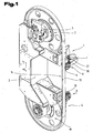
- Gemäß
Fig. 1 weist eine erfindungsgemäße Bandsägevorrichtung 1 einen Grundrahmen 2 und zwei voneinander distanziert angeordnete Umlenkräder 3, 4 auf. Weiters ist ein Antriebsmittel 5 vorgesehen, welches mit einem der Umlenkräder 3, 4 in einer Antriebsverbindung steht. Um die Umlenkräder 3, 4 ist ein endlos umlaufendes Bandsägeblatt 6 vorgesehen. Im Bereich einer zwischen den beiden Umlenkrollen gelegenen Sägeseite des Bandsägeblattes 6 steht das Bandsägeblatt 6 erfindungsgemäß mit seinem Bandrücken bzw. seitlichen Flanken mit einer oder mehreren Dämpfungsrollen 7 in einer reibschlüssigen Verbindung. In der hier dargestellten Ausführungsform sind zwei Dämpfungsrollen 7 und 8 vorgesehen. Die Dämpfungsrolle 7, 8 können an dem Grundrahmen 2 angeordnet sein. - Darüber hinaus weisen die Dämpfungsrollen 7 und 8 je eine Spurführung 9, 10 für den Bandrücken und daran anschließende seitliche Bereiche des Bandsägeblattes 6 auf. Weiters sind ein oder mehrere in
Fig. 2 mit den Bezugszeichen 11, 12 versehene Einlageelemente aus einem elastomeren, insbesondere gummielastischen Material vorgesehen. Die Einlageelemente 11, 12 werden zur Erzeugung eines Reibungsschlusses mit dem Bandsägeblatt 6 gegen die Flanken 13, 14 des Bandsägeblattes 6 gepresst. Die Presskraft, mit welcher die Einlageelemente 11 und 12 gegen das Bandsägeblatt 6 bzw. gegen dessen Flanken 13, 14 gepresst werden, kann eine durch Kompression des elastomeren Materials der Einlageelemente 11 und 12 hervorgerufene Rückstellkraft sein. - Zu einer Kompression des elastomeren Materials kann es beispielsweise dadurch kommen, dass wie in
Fig. 2 dargestellt, ein Normalabstand zwischen den Einlageelementen 11, 12, welche als O-Ringe ausgebildet sein können, kleiner ist als ein Normalabstand zwischen den Flanken des Bandsägeblattes 6. Anders gesagt ist der freie Abstand zwischen den beiden Einlageelementen 11 und 12 geringer als die Dicke des Bandsägeblattes 6. Durch Einsetzen des Bandsägeblattes 6 in die Dämpfungsrollen 7, 8 werden die Einlageelemente 11 und 12 dann komprimiert, sodass das Bandsägeblatt 6 spielfrei zwischen und von den Einlägeelementen 11, 12 gehalten ist. - Wie aus
Fig. 2 weiters ersichtlich ist, kann die Dämpfungsrolle 7 oder 8 einen Inneren Röllenkörper 15 aufweisen, der an seiner Stirnseite zwei umlaufende Einlagenuten 16, 17 für die als O-Ringe ausgebildeten Einlageelemente 11 und 12 aufweist. In der Mitte zwischen den Einlagenuten 16, 17 kann eine ebenfalls um die Stirnseite des Rollenkörpers 15 umlaufende Spurführung 18 für den Bandrücken 19 des Bandsägeblattes 6 vorgesehen sein. Weiters kann der Rollenkörper 15 von einer Öffnung durchsetzt sein, durch welche eine Drehachse 20 der Dämpfungsrolle 7 geführt sein kann. An den seitlichen Flanken des Rollenkörpers 15 können zwei Abdeckschalen 21, 22 befestigt sein, beispielsweise durch Verschrauben mit dem Rollenkörper 15. Die beiden Abdeckschalen 21 und 22 übergreifen in der dargestellten Ausführungsform zumindest abschnittsweise die beiden Einlageelemente 11 und 12, um ein ungewolltes Entfernen der O-Ringe von dem Rollenkörper 15 während des Betriebes zu verhindern. - Gemäß einer weiteren in
Fig. 3 dargestellten Ausführungsform der Erfindung kann das Einlageelement als Membran 23 ausgebildet sein, welches mittels eines Fluids, insbesondere Luft oder einer Flüssigkeit, beaufschlagbar und gegen die Flanke 13, 14 des Bandsägeblattes 6 pressbar ist. Hierzu kann eine Dämpfungsrolle eine Abdeckschale 24 aufweisen, in welcher von der Membran 23 abgedeckte Öffnungen vorgesehen sind. Durch Beaufschlagung der Membran 23 mit Druck kann diese gegen eine der Flanken 13, 14 des Bandsägeblattes 6 gedrückt werden. So kann beispielsweise ein Gebläse installiert sein, welches bei einem Vorbeidrehen der Membran 23 vor dem Gebläse die Membran 23 mittels des Erzeugten Fluidstroms gegen das Bandsägeblatt 6 presst. In diesem Fall ist es besonders vorteilhaft, wenn an der Abdeckschale 24 zumindest zwei von den Membranen 23 abgedeckte Öffnungen vorgesehen sind, sodass eine permanente Druckausübung auf das Bandsägeblatt 6 und ein durchgehender Reibungsschluss zwischen der Dämpfungsrolle mit dem Bandsägeblatt 6 gewährleistet ist. - Eine weitere alternative, in
Fig. 4 dargestellte Ausführungsform kann darin bestehen, das Bandsägeblatt 6 über Absauglöcher 25 in einer Abdeckschale 26 anzusaugen, wobei das Einlageelement in diesem Fall ebenfalls zwischen Bandsägeblatt 6 und Abdeckschale 26 angeordnet ist. Das Einlageelement bzw. die Einlageelemente können bei dieser Ausführungsform beispielsweise als O-Ring, als an den Flanken 13, 14 des Bandsägeblattes 6 anliegende Fortsätze oder als flächiges Einlageelement mit Löchern, welche mit den Absauglöchern 25 der Abdeckschale 26 korrespondieren, ausgebildet sein. - Insbesondere bei den in
Fig. 3 und 4 dargestellten Ausführungsformen kann es von Vorteil sein, wenn die Dämpfungsrolle angetrieben ist. - Aus
Fig. 1 ist ferner ersichtlich, dass die zumindest eine Dämpfungsrolle 8 um eine normal zu einer Schnitt- bzw. Sägeebene verlaufende Achse c verschwenkbar angeordnet ist und ein Sicherheitsschalter 27 zum Abschalten der Bandsägevorrichtung 1 vorgesehen ist, der durch ein Verschwenken der Dämpfungsrolle 8 um eine vorgebbare Auslenkung um die Achse c betätigt ist. - Die Dämpfungsrolle 8 kann auf einem mit einer Federkraft belasteten Arm 28 drehbar gelagert sein. Zur Erzeugung der Federkraft auf den Arm kann beispielsweise eine pneumatische, hydropneumatische oder Schraubenfeder vorgesehen sein. Der Arm 28 wiederum kann um die normal zu der Schnittebene verlaufende Achse c drehbar angeordnet sein. Unter dem Begriff Schnittebene wird in dem vorliegenden Zusammenhang die Ebene verstanden, in welcher das Bandsägeblatt 6 liegt und in der eine Trennung des zu zersägenden Werkstückes erfolgt. Die für den Sägevorgang erforderliche Vorschubkraft nimmt mit abnehmender Schärfe der Schneidezähne der Bandsägeblattes 6 zu. Überschreitet die erforderliche Vorschubkraft einen bestimmten Wert, so kann das Bandsägeblatt 6 aus seiner Sollposition gedrückt werden und mit seinen Schneidezähnen mit einem Maschinenteil der Bandsägevorrichtung 1 in Berührung kommen, beispielsweise mit einem der Umlenkräder 3, 4. Dies kann zu einer Beschädigung der Bandschneidevorrichtung zur Folge haben. Die verschwenkbar angeordnete Dämpfungsrolle 8 kann bei Überschreiten eines vorgebbaren Wert für die Vorschubkraft soweit zurück gedrängt werden, dass der Sicherheitsschalter 27 von der Dämpfungsrolle 8 bzw. dem Arm 28 oder einem mit der Dämpfungsrolle 8 oder dem Arm 28 verbundenen weiteren Bauteil betätigt wird.
- Anstelle der Feder kann auch eine mit dem Arm verbundener Kraftsensor, beispielsweise eine Kraftmessdose oder Wägezelle, vorgesehen sein, um einen Verschleiß der Schneide des Bandsägeblattes zu detektierten. Ein von dem Kraftsensor erzeugtes Signal kann an eine Auswerteeinheit, weitergeleitet werden welche einen Sicherheitsschalter betätigt und eine Abschaltung der Bandsägevorrichtung bei Überschreiten eines vorgegebenen Grenzwertes bewirkt. Die Auswerteeinheit kann beispielsweise als Mikroprozessor, Signalprozessor oder als elektronische Schaltung, insbesondere als integrierter Schaltkreis, realisiert sein. Auch kann es vorgesehen sein, dass der Sensor so ausgebildet ist, dass nur bei Überschreiten eines vorgebbaren Wertes der aufgenommenen Kraft ein Signal generiert wird. Dieses Signal kann beispielsweise direkt an den Sicherheitsschalter weitergeleitet werden und den Schalter in einen Schaltzustand bringen, welcher eine Abschaltung der Bandsägevorrichtung 1 zur Folge hat.
- Wie aus
Fig. 5 ersichtlich ist, können auf mindestens einer Seite der Dämpfungsrolle auch Magnete 29 angeordnet sein. Die Magnete 29 müssen sich hierbei nicht an der Oberfläche einer inneren Flanke der Dämpfungsrolle befinden. Sie können auch zur Gänze unterhalb der Oberfläche, d.h. innerhalb der Dämpfungsrolle angeordnet sein. Durch die Magnete 29 wird eine im Wesentlichen quer zu Bewegungsrichtung des Bandsägeblattes 6 verlaufende Kraft auf das Bandsägeblatt 6 ausgeübt, durch die das Bandsägeblatt 6 gegen eine Flanke der Dämpfungsrolle gezogen bzw. gepresst wird. - Obwohl hier mehrere Magnete 29 dargestellt sind, ist es auch möglich, dass nur ein einziger ringförmig um eine Achse der Dämpfungsrolle angeordneter Magnet 29 verwendet wird. Bei den Magneten 29 kann es sich um Permanentmagnete aber auch um Elektromagnete handeln. Permanentmagnete haben den Vorteil, dass sie sehr wartungsfrei sind und deren Einbau nur einen geringen baulichen Aufwand erfordern. Elektromagnete, wie beispielsweise stromdurchflossene Spulen, haben den Vorteil, dass mit ihnen das erzeugte Magnetfeld verändert werden kann, sodass eine Steuerung des auf das Bandsägeblatt 6 wirkenden Magnetfeldes möglich ist und daher die Stärke der Dämpfung des Bandsägeblattes 6 auch im laufenden Betrieb eingestellt werden kann.
- Der Ordnung halber sei abschließend auch darauf hingewiesen, dass zum besseren Verständnis des Aufbaus der erfindungsgemäßen Bandsägevorrichtung diese bzw. deren Bestandteile teilweise unmaßstäblich und/oder vergrößert und/oder verkleinert dargestellt wurden.
-
- 1
- Bandsägevorrichtung
- 2
- Grundrahinen
- 3
- Umlenkrad
- 4
- Umlenkrad
- 5
- Antriebsmittel
- 6
- Bandsägeblatt
- 7
- Dämpfungsrolle
- 8
- Dämpfungsrolle
- 9
- Spurführung
- 10
- Spurführung
- 11
- Einlageelement
- 12
- Einlageelement
- 13
- Flanke
- 14
- Flanke
- 15
- Rollenkörper
- 16
- Einlagenut
- 17
- Einlagenut
- 18
- Spurführung
- 19
- Bandrücken
- 20
- Drehachse
- 21
- Abdeckschale
- 22
- Abdeckschale
- 23
- Membran
- 24
- Abdeckschale
- 25
- Absauglöcher
- 26
- Abdeckschale
- 27
- Sicherheitsschalter
- 28
- Arm
- 29
- Magnet
Claims (10)
- Bandsägevorrichtung (1) umfassend einen Grundrahmen (2), zumindest zwei voneinander distanziert angeordnete Umlenkräder (3, 4), ein Antriebsmittel (5), welches mit zumindest einem der Umlenkräder (3,4) in Antriebsverbindung steht und ein um die Umlenkräder (3, 4) endlos umlaufendes Bandsägeblatt (6), wobei das Bandsägeblatt (6) im Bereich einer zwischen den beiden Umlenkrollen gelegenen Sägeseite mit zumindest einer Dämpfungsrolle (7, 8) in einer reibschlüssigen Verbindung steht und wobei die Dämpfungsrolle (7, 8) eine Spurführung (9, 10) für Bandrücken und daran anschließende seitliche Bereiche des Bandsägeblattes (6) aufweist, dadurch gekennzeichnet, dass die Dämpfungsrolle (7, 8) zumindest ein Einlageelement (11, 12) aus einem elastomeren, insbesondere gummielastischen, Material aufweist, welches gegen eine Flanke des Bandsägeblattes (6) gepresst ist.
- Bandsägevorrichtung nach Anspruch 1, dadurch gekennzeichnet, dass das zumindest eine Einlageelement (11, 12) durch eine von dem elastomeren Material hervorgerufene Rückstellkraft gegen die Flanke des Bandsägeblattes (6) gepresst ist.
- Bandsägevorrichtung nach Anspruch 2, dadurch gekennzeichnet, dass das zumindest eine Einlageelement als O-Ring ausgebildet ist.
- Bandsägevorrichtung nach Anspruch 2 oder 3, dadurch gekennzeichnet, dass die Dämpfungsrolle (7, 8) zumindest zwei Einlageelemente (11,12) aufweist, welche an einander gegenüberliegenden Flanken (13,14) des Bandsägeblattes (6) anliegen, und ein Normalabstand zwischen den Einlageelementen (11, 12) kleiner ist als ein Normalabstand zwischen den Flanken des Bandsägeblattes (6), wobei das Bandsägeblatt (6) spielfrei zwischen und von den Einlageelementen (11,12) gehalten ist.
- Bandsägevorrichtung nach einem der Ansprüche 2 oder 4, dadurch gekennzeichnet, dass das zumindest eine Einlageelement als Membran (23) ausgebildet ist, welche mittels eines Fluids, insbesondere Luft oder einer Flüssigkeit, beaufschlagbar und gegen die Flanke (13, 14) des Bandsägeblattes (6), pressbar ist.
- Bandsägevorrichtung nach einem der Ansprüche 1 bis 5, dadurch gekennzeichnet, dass die zumindest eine Dämpfungsrolle (8) um eine normal zu einer Schnittebene verlaufende Achse (c) verschwenkbar angeordnet ist und ein Sicherheitsschalter (27) zum Abschalten der Band- I. sägevomchtung (1) vorgesehen ist, der durch ein Verschwenken der Dämpfungsrolle (8) um eine vorgebbare Auslenkung betätigt ist und/oder dass ein mit einem Arm (28) verbundener Kraftaufnehmer, beispielsweise eine Wägezelle oder Kraftmessdose, vorgesehen ist, um einen Verschleiß des Bandsägeblatte zu detektieren.
- Bandsägevorrichtung nach Anspruch 6, dadurch gekennzeichnet, dass die Dämpfungsrolle (8) auf zumindest einem mit einer Federkraft belasteten Arm (28) drehbar gelagert ist, wobei der Arm (28) um die normal zu der Schnittebene verlaufende Achse (c) drehbar angeordnet ist.
- Bandsägevorrichtung nach einem der Ansprüche 1 bis 7, dadurch gekennzeichnet, dass die zumindest eine Dämpfungsrolle (7, 8) an dem Grundrahmen (2) angeordnet ist.
- Bandsägevorrichtung nach einem der Ansprüche 1 bis 8, dadurch gekennzeichnet, dass die zumindest eine Dämpfungsrolle (7, 8) angetrieben ist.
- Bandsägevoirichtung (1) umfassend einen Grundrahmen (2), zumindest zwei voneinander distanziert angeordnete Umlenkräder (3, 4), ein Antriebsmittel (5), welches mit zumindest einem der Umlenkräder (3, 4) in Antriebsverbindung steht und ein um die Umlenkräder (3, 4) endlos umlaufendes Bandsägeblatt (6), wobei das Bandsägeblatt (6) im Bereich einer zwischen den beiden Umlenkrollen gelegenen Sägeseite mit zumindest einer Dämpfungsrolle (7, 8) in einer reibschlüssigen Verbindung steht, wobei die Dämpfungsrolle (7, 8) eine Spurführung (9, 10) für den Bandrücken und daran anschließende seitliche Bereiche des Bandsägeblattes (6) aufweist dadurch gekennzeichnet, dass wobei die zumindest eine Dämpfungsrolle (7, 8) zumindest einen Magnet (29) aufweist und der Magnet (29) an einer inneren Flanke der Dämpfungsrolle angeordnet ist.
Priority Applications (1)
| Application Number | Priority Date | Filing Date | Title |
|---|---|---|---|
| PL12724850T PL2699374T3 (pl) | 2011-04-20 | 2012-04-18 | Wałek tłumiący |
Applications Claiming Priority (4)
| Application Number | Priority Date | Filing Date | Title |
|---|---|---|---|
| AT5672011A AT511063B1 (de) | 2011-04-20 | 2011-04-20 | Bandsägevorrichtung |
| AT11922011 | 2011-08-18 | ||
| ATA1380/2011A AT511468B1 (de) | 2011-04-20 | 2011-09-23 | Dämpfungsrolle |
| PCT/AT2012/050052 WO2012142644A2 (de) | 2011-04-20 | 2012-04-18 | Dämpfungsrolle |
Publications (2)
| Publication Number | Publication Date |
|---|---|
| EP2699374A2 EP2699374A2 (de) | 2014-02-26 |
| EP2699374B1 true EP2699374B1 (de) | 2015-08-12 |
Family
ID=46201033
Family Applications (1)
| Application Number | Title | Priority Date | Filing Date |
|---|---|---|---|
| EP12724850.8A Not-in-force EP2699374B1 (de) | 2011-04-20 | 2012-04-18 | Dämpfungsrolle |
Country Status (6)
| Country | Link |
|---|---|
| EP (1) | EP2699374B1 (de) |
| CN (1) | CN103547400B (de) |
| AT (1) | AT511468B1 (de) |
| HU (1) | HUE025781T2 (de) |
| PL (1) | PL2699374T3 (de) |
| WO (1) | WO2012142644A2 (de) |
Cited By (1)
| Publication number | Priority date | Publication date | Assignee | Title |
|---|---|---|---|---|
| DE102024106030A1 (de) * | 2024-03-01 | 2025-09-04 | Albrecht Bäumer GmbH & Co.KG Spezialmaschinenfabrik | Vorrichtung zum Messerschneiden oder Sägen von Werkstücken mit einer Überwachung der Bandschädigung, Verfahren zur Überwachung des Schädigungszustandes eines Bandmessers bzw. einer Bandsäge |
Families Citing this family (4)
| Publication number | Priority date | Publication date | Assignee | Title |
|---|---|---|---|---|
| CN108437075A (zh) * | 2018-03-09 | 2018-08-24 | 佛山市顺德区林粲机械设备有限公司 | 立式带锯机 |
| CN113059234A (zh) * | 2021-03-29 | 2021-07-02 | 江苏奕骏重工机械制造有限公司 | 一种带有锯条自清洁功能的带锯床 |
| CN117245143A (zh) * | 2023-09-20 | 2023-12-19 | 浙江奥林发机床有限公司 | 一种带夹紧防偏移机构的带锯床 |
| CN118989456B (zh) * | 2024-08-27 | 2025-05-13 | 扬州中辉机电有限公司 | 一种带有自润滑锯带导块的立式锯床 |
Family Cites Families (16)
| Publication number | Priority date | Publication date | Assignee | Title |
|---|---|---|---|---|
| US537576A (en) * | 1895-04-16 | Stephen lounsberry | ||
| US365441A (en) * | 1887-06-28 | Guide for band-saws | ||
| US334175A (en) * | 1886-01-12 | Half to tilghman schadt | ||
| DE160229C (de) * | ||||
| US2602987A (en) * | 1947-03-05 | 1952-07-15 | Wells Mfg Company | Band saw |
| US2783793A (en) * | 1953-06-03 | 1957-03-05 | Solar Aircraft Co | Linear saw blade guide |
| US3680417A (en) * | 1970-04-27 | 1972-08-01 | W F Wells And Sons Inc | Sensor for determining band saw blade deflection |
| DK164312C (da) * | 1990-02-20 | 1992-11-02 | Hovmoeller Hyldig J M | Styr for et skaerebaand til baandskaeremaskine |
| CN1187402A (zh) * | 1997-01-04 | 1998-07-15 | 张圣玉 | 带锯机 |
| DE29918249U1 (de) * | 1999-10-18 | 2000-03-02 | Hans Kaltenbach Maschinenfabrik GmbH & Co. KG, 79539 Lörrach | Bandsägemaschine mit einem zum Führen des Bandrückens dienenden Führungselement |
| DE102004020990B4 (de) * | 2004-04-23 | 2008-05-21 | Schott Ag | Vorrichtung und Verfahren zur Erzeugung von Mikrostrukturen |
| DE102006037705A1 (de) * | 2006-08-11 | 2008-02-14 | Carl Zeiss Smt Ag | Sägevorrichtung |
| JP2008229742A (ja) * | 2007-03-16 | 2008-10-02 | Nicotec Co Ltd | 帯鋸盤 |
| CN101125382A (zh) * | 2007-09-29 | 2008-02-20 | 卢建飞 | 数控纵横锯切金属带锯床 |
| DE102008018443A1 (de) * | 2008-04-08 | 2009-10-15 | Esterer Wd Gmbh | Bandsäge |
| DE202009009839U1 (de) * | 2009-07-18 | 2009-10-01 | Messner, Britta | Führungssystem aus Kunststoff für Bandsägen |
-
2011
- 2011-09-23 AT ATA1380/2011A patent/AT511468B1/de not_active IP Right Cessation
-
2012
- 2012-04-18 HU HUE12724850A patent/HUE025781T2/en unknown
- 2012-04-18 WO PCT/AT2012/050052 patent/WO2012142644A2/de not_active Ceased
- 2012-04-18 CN CN201280019019.XA patent/CN103547400B/zh not_active Expired - Fee Related
- 2012-04-18 EP EP12724850.8A patent/EP2699374B1/de not_active Not-in-force
- 2012-04-18 PL PL12724850T patent/PL2699374T3/pl unknown
Cited By (1)
| Publication number | Priority date | Publication date | Assignee | Title |
|---|---|---|---|---|
| DE102024106030A1 (de) * | 2024-03-01 | 2025-09-04 | Albrecht Bäumer GmbH & Co.KG Spezialmaschinenfabrik | Vorrichtung zum Messerschneiden oder Sägen von Werkstücken mit einer Überwachung der Bandschädigung, Verfahren zur Überwachung des Schädigungszustandes eines Bandmessers bzw. einer Bandsäge |
Also Published As
| Publication number | Publication date |
|---|---|
| HUE025781T2 (en) | 2016-05-30 |
| WO2012142644A3 (de) | 2012-12-13 |
| EP2699374A2 (de) | 2014-02-26 |
| AT511468B1 (de) | 2012-12-15 |
| CN103547400B (zh) | 2016-06-22 |
| CN103547400A (zh) | 2014-01-29 |
| WO2012142644A2 (de) | 2012-10-26 |
| PL2699374T3 (pl) | 2016-01-29 |
| AT511468A4 (de) | 2012-12-15 |
Similar Documents
| Publication | Publication Date | Title |
|---|---|---|
| EP2024122B1 (de) | Bandsäge und verfahren zum positionieren eines bandsägeblatts im raum | |
| AT511468B1 (de) | Dämpfungsrolle | |
| DE202009001440U1 (de) | Kraftgetriebenes Handwerkzeug mit Spanneinrichtung für ein Werkzeug | |
| EP3260228B1 (de) | Sägemaschine und führungseinrichtung für ein sägeband oder sägeblatt einer sägemaschine | |
| EP3597300A1 (de) | Walzenpakete für vermahlungsvorrichtungen, vermahlungsvorrichtungen und verfahren | |
| EP3710325B1 (de) | Elektromechanisch schaltbare bremse mit integraler dämpferstruktur | |
| EP2772338A1 (de) | Bearbeitungsanordnung mit einer Tasteinrichtung | |
| EP0277260B1 (de) | Vorrichtung zum Schneiden von folienartigen Werkstoffen | |
| DE29918249U1 (de) | Bandsägemaschine mit einem zum Führen des Bandrückens dienenden Führungselement | |
| AT509858B1 (de) | Verfahren und vorrichtung zum führen eines sägewerkzeugs | |
| EP1985419B1 (de) | Schneidvorrichtung zum Kürzen von Bauelementgurten, Zuführeinrichtung und Bestückautomat | |
| DE4306087C2 (de) | Vorschubspindelmechanismus mit einer Schwingungsdämpfungsvorrichtung | |
| DE102008033425A1 (de) | Stranggranulator mit Schneidspaltverstellung | |
| AT511063B1 (de) | Bandsägevorrichtung | |
| AT518348A1 (de) | Bearbeitungsanlage zum Bearbeiten von Rundmaterial | |
| EP1216122A1 (de) | Messerhalter mit stossabsorber für eine einrichtung zum längsteilen einer materialbahn | |
| EP1615759A1 (de) | Antriebseinheit für einen granulator | |
| EP2730427B1 (de) | Vorrichtung zur Aufnahme einer Überlast in einer Rückenbearbeitungsstation einer Buchbindemaschine | |
| DE202008002323U1 (de) | Vorrichtung zum Aufteilen großformatiger plattenförmiger Werkstücke | |
| DE4423605B4 (de) | Lagerung für einen Offenend-Spinnrotor | |
| EP1155789B1 (de) | Perforiergerät mit Feineinstellung | |
| EP1116680A2 (de) | Spulmaschine | |
| DE102013221349A1 (de) | Antriebseinheit | |
| DE69215249T2 (de) | Präzisions-Überlastkupplungsvorrichtung für automatisierte Maschinen | |
| EP1985420A1 (de) | Schneidvorrichtung zum Kürzen von Bauelementgurten, Zuführeinrichtung und Bestückautomat |
Legal Events
| Date | Code | Title | Description |
|---|---|---|---|
| PUAI | Public reference made under article 153(3) epc to a published international application that has entered the european phase |
Free format text: ORIGINAL CODE: 0009012 |
|
| 17P | Request for examination filed |
Effective date: 20131119 |
|
| AK | Designated contracting states |
Kind code of ref document: A2 Designated state(s): AL AT BE BG CH CY CZ DE DK EE ES FI FR GB GR HR HU IE IS IT LI LT LU LV MC MK MT NL NO PL PT RO RS SE SI SK SM TR |
|
| DAX | Request for extension of the european patent (deleted) | ||
| GRAP | Despatch of communication of intention to grant a patent |
Free format text: ORIGINAL CODE: EPIDOSNIGR1 |
|
| INTG | Intention to grant announced |
Effective date: 20150313 |
|
| GRAS | Grant fee paid |
Free format text: ORIGINAL CODE: EPIDOSNIGR3 |
|
| GRAA | (expected) grant |
Free format text: ORIGINAL CODE: 0009210 |
|
| AK | Designated contracting states |
Kind code of ref document: B1 Designated state(s): AL AT BE BG CH CY CZ DE DK EE ES FI FR GB GR HR HU IE IS IT LI LT LU LV MC MK MT NL NO PL PT RO RS SE SI SK SM TR |
|
| REG | Reference to a national code |
Ref country code: GB Ref legal event code: FG4D Free format text: NOT ENGLISH |
|
| REG | Reference to a national code |
Ref country code: CH Ref legal event code: EP |
|
| REG | Reference to a national code |
Ref country code: AT Ref legal event code: REF Ref document number: 741682 Country of ref document: AT Kind code of ref document: T Effective date: 20150815 |
|
| REG | Reference to a national code |
Ref country code: IE Ref legal event code: FG4D Free format text: LANGUAGE OF EP DOCUMENT: GERMAN |
|
| REG | Reference to a national code |
Ref country code: DE Ref legal event code: R096 Ref document number: 502012004134 Country of ref document: DE |
|
| REG | Reference to a national code |
Ref country code: LT Ref legal event code: MG4D |
|
| REG | Reference to a national code |
Ref country code: NL Ref legal event code: MP Effective date: 20150812 |
|
| PG25 | Lapsed in a contracting state [announced via postgrant information from national office to epo] |
Ref country code: LV Free format text: LAPSE BECAUSE OF FAILURE TO SUBMIT A TRANSLATION OF THE DESCRIPTION OR TO PAY THE FEE WITHIN THE PRESCRIBED TIME-LIMIT Effective date: 20150812 Ref country code: GR Free format text: LAPSE BECAUSE OF FAILURE TO SUBMIT A TRANSLATION OF THE DESCRIPTION OR TO PAY THE FEE WITHIN THE PRESCRIBED TIME-LIMIT Effective date: 20151113 Ref country code: FI Free format text: LAPSE BECAUSE OF FAILURE TO SUBMIT A TRANSLATION OF THE DESCRIPTION OR TO PAY THE FEE WITHIN THE PRESCRIBED TIME-LIMIT Effective date: 20150812 Ref country code: NO Free format text: LAPSE BECAUSE OF FAILURE TO SUBMIT A TRANSLATION OF THE DESCRIPTION OR TO PAY THE FEE WITHIN THE PRESCRIBED TIME-LIMIT Effective date: 20151112 Ref country code: LT Free format text: LAPSE BECAUSE OF FAILURE TO SUBMIT A TRANSLATION OF THE DESCRIPTION OR TO PAY THE FEE WITHIN THE PRESCRIBED TIME-LIMIT Effective date: 20150812 |
|
| PG25 | Lapsed in a contracting state [announced via postgrant information from national office to epo] |
Ref country code: ES Free format text: LAPSE BECAUSE OF FAILURE TO SUBMIT A TRANSLATION OF THE DESCRIPTION OR TO PAY THE FEE WITHIN THE PRESCRIBED TIME-LIMIT Effective date: 20150812 Ref country code: RS Free format text: LAPSE BECAUSE OF FAILURE TO SUBMIT A TRANSLATION OF THE DESCRIPTION OR TO PAY THE FEE WITHIN THE PRESCRIBED TIME-LIMIT Effective date: 20150812 Ref country code: PT Free format text: LAPSE BECAUSE OF FAILURE TO SUBMIT A TRANSLATION OF THE DESCRIPTION OR TO PAY THE FEE WITHIN THE PRESCRIBED TIME-LIMIT Effective date: 20151214 Ref country code: HR Free format text: LAPSE BECAUSE OF FAILURE TO SUBMIT A TRANSLATION OF THE DESCRIPTION OR TO PAY THE FEE WITHIN THE PRESCRIBED TIME-LIMIT Effective date: 20150812 Ref country code: SE Free format text: LAPSE BECAUSE OF FAILURE TO SUBMIT A TRANSLATION OF THE DESCRIPTION OR TO PAY THE FEE WITHIN THE PRESCRIBED TIME-LIMIT Effective date: 20150812 Ref country code: IS Free format text: LAPSE BECAUSE OF FAILURE TO SUBMIT A TRANSLATION OF THE DESCRIPTION OR TO PAY THE FEE WITHIN THE PRESCRIBED TIME-LIMIT Effective date: 20151212 |
|
| PG25 | Lapsed in a contracting state [announced via postgrant information from national office to epo] |
Ref country code: NL Free format text: LAPSE BECAUSE OF FAILURE TO SUBMIT A TRANSLATION OF THE DESCRIPTION OR TO PAY THE FEE WITHIN THE PRESCRIBED TIME-LIMIT Effective date: 20150812 |
|
| PG25 | Lapsed in a contracting state [announced via postgrant information from national office to epo] |
Ref country code: EE Free format text: LAPSE BECAUSE OF FAILURE TO SUBMIT A TRANSLATION OF THE DESCRIPTION OR TO PAY THE FEE WITHIN THE PRESCRIBED TIME-LIMIT Effective date: 20150812 Ref country code: SK Free format text: LAPSE BECAUSE OF FAILURE TO SUBMIT A TRANSLATION OF THE DESCRIPTION OR TO PAY THE FEE WITHIN THE PRESCRIBED TIME-LIMIT Effective date: 20150812 Ref country code: DK Free format text: LAPSE BECAUSE OF FAILURE TO SUBMIT A TRANSLATION OF THE DESCRIPTION OR TO PAY THE FEE WITHIN THE PRESCRIBED TIME-LIMIT Effective date: 20150812 Ref country code: CZ Free format text: LAPSE BECAUSE OF FAILURE TO SUBMIT A TRANSLATION OF THE DESCRIPTION OR TO PAY THE FEE WITHIN THE PRESCRIBED TIME-LIMIT Effective date: 20150812 Ref country code: IT Free format text: LAPSE BECAUSE OF FAILURE TO SUBMIT A TRANSLATION OF THE DESCRIPTION OR TO PAY THE FEE WITHIN THE PRESCRIBED TIME-LIMIT Effective date: 20150812 |
|
| REG | Reference to a national code |
Ref country code: DE Ref legal event code: R097 Ref document number: 502012004134 Country of ref document: DE |
|
| REG | Reference to a national code |
Ref country code: HU Ref legal event code: AG4A Ref document number: E025781 Country of ref document: HU |
|
| PG25 | Lapsed in a contracting state [announced via postgrant information from national office to epo] |
Ref country code: RO Free format text: LAPSE BECAUSE OF FAILURE TO SUBMIT A TRANSLATION OF THE DESCRIPTION OR TO PAY THE FEE WITHIN THE PRESCRIBED TIME-LIMIT Effective date: 20150812 |
|
| PLBE | No opposition filed within time limit |
Free format text: ORIGINAL CODE: 0009261 |
|
| STAA | Information on the status of an ep patent application or granted ep patent |
Free format text: STATUS: NO OPPOSITION FILED WITHIN TIME LIMIT |
|
| 26N | No opposition filed |
Effective date: 20160513 |
|
| PG25 | Lapsed in a contracting state [announced via postgrant information from national office to epo] |
Ref country code: SI Free format text: LAPSE BECAUSE OF FAILURE TO SUBMIT A TRANSLATION OF THE DESCRIPTION OR TO PAY THE FEE WITHIN THE PRESCRIBED TIME-LIMIT Effective date: 20150812 Ref country code: BE Free format text: LAPSE BECAUSE OF NON-PAYMENT OF DUE FEES Effective date: 20160430 |
|
| REG | Reference to a national code |
Ref country code: CH Ref legal event code: PL |
|
| GBPC | Gb: european patent ceased through non-payment of renewal fee |
Effective date: 20160418 |
|
| PG25 | Lapsed in a contracting state [announced via postgrant information from national office to epo] |
Ref country code: LU Free format text: LAPSE BECAUSE OF FAILURE TO SUBMIT A TRANSLATION OF THE DESCRIPTION OR TO PAY THE FEE WITHIN THE PRESCRIBED TIME-LIMIT Effective date: 20160418 |
|
| REG | Reference to a national code |
Ref country code: IE Ref legal event code: MM4A |
|
| REG | Reference to a national code |
Ref country code: FR Ref legal event code: ST Effective date: 20161230 |
|
| PG25 | Lapsed in a contracting state [announced via postgrant information from national office to epo] |
Ref country code: CH Free format text: LAPSE BECAUSE OF NON-PAYMENT OF DUE FEES Effective date: 20160430 Ref country code: LI Free format text: LAPSE BECAUSE OF NON-PAYMENT OF DUE FEES Effective date: 20160430 Ref country code: GB Free format text: LAPSE BECAUSE OF NON-PAYMENT OF DUE FEES Effective date: 20160418 Ref country code: FR Free format text: LAPSE BECAUSE OF NON-PAYMENT OF DUE FEES Effective date: 20160502 |
|
| PG25 | Lapsed in a contracting state [announced via postgrant information from national office to epo] |
Ref country code: IE Free format text: LAPSE BECAUSE OF NON-PAYMENT OF DUE FEES Effective date: 20160418 |
|
| PG25 | Lapsed in a contracting state [announced via postgrant information from national office to epo] |
Ref country code: CY Free format text: LAPSE BECAUSE OF FAILURE TO SUBMIT A TRANSLATION OF THE DESCRIPTION OR TO PAY THE FEE WITHIN THE PRESCRIBED TIME-LIMIT Effective date: 20150812 Ref country code: SM Free format text: LAPSE BECAUSE OF FAILURE TO SUBMIT A TRANSLATION OF THE DESCRIPTION OR TO PAY THE FEE WITHIN THE PRESCRIBED TIME-LIMIT Effective date: 20150812 |
|
| PG25 | Lapsed in a contracting state [announced via postgrant information from national office to epo] |
Ref country code: MT Free format text: LAPSE BECAUSE OF FAILURE TO SUBMIT A TRANSLATION OF THE DESCRIPTION OR TO PAY THE FEE WITHIN THE PRESCRIBED TIME-LIMIT Effective date: 20150812 Ref country code: TR Free format text: LAPSE BECAUSE OF FAILURE TO SUBMIT A TRANSLATION OF THE DESCRIPTION OR TO PAY THE FEE WITHIN THE PRESCRIBED TIME-LIMIT Effective date: 20150812 Ref country code: MC Free format text: LAPSE BECAUSE OF FAILURE TO SUBMIT A TRANSLATION OF THE DESCRIPTION OR TO PAY THE FEE WITHIN THE PRESCRIBED TIME-LIMIT Effective date: 20150812 Ref country code: MK Free format text: LAPSE BECAUSE OF FAILURE TO SUBMIT A TRANSLATION OF THE DESCRIPTION OR TO PAY THE FEE WITHIN THE PRESCRIBED TIME-LIMIT Effective date: 20150812 |
|
| REG | Reference to a national code |
Ref country code: DE Ref legal event code: R082 Ref document number: 502012004134 Country of ref document: DE Representative=s name: ABP BURGER RECHTSANWALTSGESELLSCHAFT MBH, DE |
|
| PG25 | Lapsed in a contracting state [announced via postgrant information from national office to epo] |
Ref country code: BG Free format text: LAPSE BECAUSE OF FAILURE TO SUBMIT A TRANSLATION OF THE DESCRIPTION OR TO PAY THE FEE WITHIN THE PRESCRIBED TIME-LIMIT Effective date: 20150812 |
|
| PG25 | Lapsed in a contracting state [announced via postgrant information from national office to epo] |
Ref country code: AL Free format text: LAPSE BECAUSE OF FAILURE TO SUBMIT A TRANSLATION OF THE DESCRIPTION OR TO PAY THE FEE WITHIN THE PRESCRIBED TIME-LIMIT Effective date: 20150812 |
|
| PGFP | Annual fee paid to national office [announced via postgrant information from national office to epo] |
Ref country code: PL Payment date: 20190426 Year of fee payment: 13 |
|
| PGFP | Annual fee paid to national office [announced via postgrant information from national office to epo] |
Ref country code: HU Payment date: 20190412 Year of fee payment: 8 |
|
| PGFP | Annual fee paid to national office [announced via postgrant information from national office to epo] |
Ref country code: AT Payment date: 20190411 Year of fee payment: 8 |
|
| PGFP | Annual fee paid to national office [announced via postgrant information from national office to epo] |
Ref country code: DE Payment date: 20200327 Year of fee payment: 9 |
|
| REG | Reference to a national code |
Ref country code: AT Ref legal event code: MM01 Ref document number: 741682 Country of ref document: AT Kind code of ref document: T Effective date: 20200418 |
|
| PG25 | Lapsed in a contracting state [announced via postgrant information from national office to epo] |
Ref country code: HU Free format text: LAPSE BECAUSE OF NON-PAYMENT OF DUE FEES Effective date: 20200419 Ref country code: AT Free format text: LAPSE BECAUSE OF NON-PAYMENT OF DUE FEES Effective date: 20200418 |
|
| REG | Reference to a national code |
Ref country code: DE Ref legal event code: R119 Ref document number: 502012004134 Country of ref document: DE |
|
| PG25 | Lapsed in a contracting state [announced via postgrant information from national office to epo] |
Ref country code: DE Free format text: LAPSE BECAUSE OF NON-PAYMENT OF DUE FEES Effective date: 20211103 |
|
| PG25 | Lapsed in a contracting state [announced via postgrant information from national office to epo] |
Ref country code: PL Free format text: LAPSE BECAUSE OF NON-PAYMENT OF DUE FEES Effective date: 20200418 |