EP2695027B1 - Safety in dynamic 3d healthcare environment - Google Patents
Safety in dynamic 3d healthcare environment Download PDFInfo
- Publication number
- EP2695027B1 EP2695027B1 EP12715199.1A EP12715199A EP2695027B1 EP 2695027 B1 EP2695027 B1 EP 2695027B1 EP 12715199 A EP12715199 A EP 12715199A EP 2695027 B1 EP2695027 B1 EP 2695027B1
- Authority
- EP
- European Patent Office
- Prior art keywords
- free space
- space model
- movement
- depth information
- arrangement
- Prior art date
- Legal status (The legal status is an assumption and is not a legal conclusion. Google has not performed a legal analysis and makes no representation as to the accuracy of the status listed.)
- Active
Links
Images


Classifications
-
- A—HUMAN NECESSITIES
- A61—MEDICAL OR VETERINARY SCIENCE; HYGIENE
- A61B—DIAGNOSIS; SURGERY; IDENTIFICATION
- A61B6/00—Apparatus or devices for radiation diagnosis; Apparatus or devices for radiation diagnosis combined with radiation therapy equipment
- A61B6/10—Safety means specially adapted therefor
- A61B6/102—Protection against mechanical damage, e.g. anti-collision devices
-
- G—PHYSICS
- G05—CONTROLLING; REGULATING
- G05B—CONTROL OR REGULATING SYSTEMS IN GENERAL; FUNCTIONAL ELEMENTS OF SUCH SYSTEMS; MONITORING OR TESTING ARRANGEMENTS FOR SUCH SYSTEMS OR ELEMENTS
- G05B19/00—Program-control systems
- G05B19/02—Program-control systems electric
- G05B19/18—Numerical control [NC], i.e. automatically operating machines, in particular machine tools, e.g. in a manufacturing environment, so as to execute positioning, movement or co-ordinated operations by means of program data in numerical form
- G05B19/406—Numerical control [NC], i.e. automatically operating machines, in particular machine tools, e.g. in a manufacturing environment, so as to execute positioning, movement or co-ordinated operations by means of program data in numerical form characterised by monitoring or safety
- G05B19/4061—Avoiding collision or forbidden zones
-
- A—HUMAN NECESSITIES
- A61—MEDICAL OR VETERINARY SCIENCE; HYGIENE
- A61B—DIAGNOSIS; SURGERY; IDENTIFICATION
- A61B6/00—Apparatus or devices for radiation diagnosis; Apparatus or devices for radiation diagnosis combined with radiation therapy equipment
- A61B6/54—Control of apparatus or devices for radiation diagnosis
- A61B6/547—Control of apparatus or devices for radiation diagnosis involving tracking of position of the device or parts of the device
-
- B—PERFORMING OPERATIONS; TRANSPORTING
- B25—HAND TOOLS; PORTABLE POWER-DRIVEN TOOLS; MANIPULATORS
- B25J—MANIPULATORS; CHAMBERS PROVIDED WITH MANIPULATION DEVICES
- B25J9/00—Program-controlled manipulators
- B25J9/16—Program controls
- B25J9/1656—Program controls characterised by programming, planning systems for manipulators
- B25J9/1664—Program controls characterised by programming, planning systems for manipulators characterised by motion, path, trajectory planning
- B25J9/1666—Avoiding collision or forbidden zones
-
- G—PHYSICS
- G05—CONTROLLING; REGULATING
- G05B—CONTROL OR REGULATING SYSTEMS IN GENERAL; FUNCTIONAL ELEMENTS OF SUCH SYSTEMS; MONITORING OR TESTING ARRANGEMENTS FOR SUCH SYSTEMS OR ELEMENTS
- G05B19/00—Program-control systems
- G05B19/02—Program-control systems electric
- G05B19/18—Numerical control [NC], i.e. automatically operating machines, in particular machine tools, e.g. in a manufacturing environment, so as to execute positioning, movement or co-ordinated operations by means of program data in numerical form
- G05B19/406—Numerical control [NC], i.e. automatically operating machines, in particular machine tools, e.g. in a manufacturing environment, so as to execute positioning, movement or co-ordinated operations by means of program data in numerical form characterised by monitoring or safety
-
- G—PHYSICS
- G06—COMPUTING OR CALCULATING; COUNTING
- G06T—IMAGE DATA PROCESSING OR GENERATION, IN GENERAL
- G06T19/00—Manipulating three-dimensional [3D] models or images for computer graphics
-
- H—ELECTRICITY
- H04—ELECTRIC COMMUNICATION TECHNIQUE
- H04N—PICTORIAL COMMUNICATION, e.g. TELEVISION
- H04N7/00—Television systems
- H04N7/18—Closed-circuit television [CCTV] systems, i.e. systems in which the video signal is not broadcast
- H04N7/183—Closed-circuit television [CCTV] systems, i.e. systems in which the video signal is not broadcast for receiving images from a single remote source
-
- G—PHYSICS
- G05—CONTROLLING; REGULATING
- G05B—CONTROL OR REGULATING SYSTEMS IN GENERAL; FUNCTIONAL ELEMENTS OF SUCH SYSTEMS; MONITORING OR TESTING ARRANGEMENTS FOR SUCH SYSTEMS OR ELEMENTS
- G05B2219/00—Program-control systems
- G05B2219/30—Nc systems
- G05B2219/37—Measurements
- G05B2219/37567—3-D vision, stereo vision, with two cameras
-
- G—PHYSICS
- G05—CONTROLLING; REGULATING
- G05B—CONTROL OR REGULATING SYSTEMS IN GENERAL; FUNCTIONAL ELEMENTS OF SUCH SYSTEMS; MONITORING OR TESTING ARRANGEMENTS FOR SUCH SYSTEMS OR ELEMENTS
- G05B2219/00—Program-control systems
- G05B2219/30—Nc systems
- G05B2219/39—Robotics, robotics to robotics hand
- G05B2219/39082—Collision, real time collision avoidance
-
- G—PHYSICS
- G05—CONTROLLING; REGULATING
- G05B—CONTROL OR REGULATING SYSTEMS IN GENERAL; FUNCTIONAL ELEMENTS OF SUCH SYSTEMS; MONITORING OR TESTING ARRANGEMENTS FOR SUCH SYSTEMS OR ELEMENTS
- G05B2219/00—Program-control systems
- G05B2219/30—Nc systems
- G05B2219/39—Robotics, robotics to robotics hand
- G05B2219/39091—Avoid collision with moving obstacles
-
- G—PHYSICS
- G05—CONTROLLING; REGULATING
- G05B—CONTROL OR REGULATING SYSTEMS IN GENERAL; FUNCTIONAL ELEMENTS OF SUCH SYSTEMS; MONITORING OR TESTING ARRANGEMENTS FOR SUCH SYSTEMS OR ELEMENTS
- G05B2219/00—Program-control systems
- G05B2219/30—Nc systems
- G05B2219/40—Robotics, robotics mapping to robotics vision
- G05B2219/40607—Fixed camera to observe workspace, object, workpiece, global
-
- G—PHYSICS
- G05—CONTROLLING; REGULATING
- G05B—CONTROL OR REGULATING SYSTEMS IN GENERAL; FUNCTIONAL ELEMENTS OF SUCH SYSTEMS; MONITORING OR TESTING ARRANGEMENTS FOR SUCH SYSTEMS OR ELEMENTS
- G05B2219/00—Program-control systems
- G05B2219/30—Nc systems
- G05B2219/45—Nc applications
- G05B2219/45117—Medical, radio surgery manipulator
-
- G—PHYSICS
- G06—COMPUTING OR CALCULATING; COUNTING
- G06T—IMAGE DATA PROCESSING OR GENERATION, IN GENERAL
- G06T2210/00—Indexing scheme for image generation or computer graphics
- G06T2210/21—Collision detection, intersection
-
- G—PHYSICS
- G06—COMPUTING OR CALCULATING; COUNTING
- G06T—IMAGE DATA PROCESSING OR GENERATION, IN GENERAL
- G06T2210/00—Indexing scheme for image generation or computer graphics
- G06T2210/41—Medical
Definitions
- the present invention relates to safety in dynamic 3D healthcare environments.
- the invention in particular relates to a medical safety-system for dynamic 3D healthcare environments, a medical examination system with motorized equipment, an image acquisition arrangement, a method for providing safe movements in dynamic 3D healthcare environments, a computer program element and a computer readable medium.
- US 2008/003341 A1 describes an automated laser treatment system with real-time integrated 3D vision system for laser debridement.
- a modeling system is provided with a camera and the modeling system is provided for modeling an identified area of the skin of a patient, which skin is to be treated.
- a laser system has a laser head for directing a laser to at least a portion of the identified area of the skin to be treated.
- a 3D map of the determined part of the surface of the patient body is developed. The actual position of the laser is compared with a plant positioning and a shutdown of the treatment process is provided for safe operation of the system.
- the 3D vision system provides a high-resolution 3D surface shape measurement and mapping for generating the 3D map of the patient's surface.
- EP 1 717 757 A1 describes a method for graphically representing the surrounding of a vehicle.
- a medical safety-system for dynamic 3D healthcare environments comprising a detection system, a processing unit, and an interface unit.
- the detection system comprises at least one sensor arrangement adapted to provide depth information of at least a part of an observed scene.
- the processing unit comprises a correlation unit adapted to correlate the depth information.
- the processing unit comprises a generation unit adapted to generate a 3D free space model.
- the interface unit is adapted to provide the 3D free space model.
- 3D free space model refers to spatial or volumetric data defining a space which is free of objects and structures and which can thus be used for movement, for example of a component or an element.
- the detection system comprises at least one time-of-flight camera as sensor arrangement.
- a plurality of sensors is placed in such a way that objects can be seen by multiple sensors from multiple angles.
- a medical examination system with motorized equipment comprising a motorized functional system and a medical safety-system according to one of the above described aspects or embodiments.
- the motorized functional system comprises a movable arrangement to perform at least one task.
- An adaptable movement restriction device is provided, which is adapted to restrict the movement of the arrangement to movements inside the 3D free space model provided by the interface unit.
- the motorized functional system of the medical examination system is an image acquisition arrangement with a movable arrangement to acquire image data of an object from different projections.
- the image acquisition arrangement comprises a movable C-arm structure with an X-ray source and an X-ray detector arranged on opposing ends of the C-arm structure.
- the movement possibilities of the C-arm structure are limited to the 3D free space model.
- a method for providing safe movements in dynamic 3D healthcare environments comprising the following steps: In a provision step, depth information of at least a part of an observed scene is provided. The depth information is correlated in a correlation step. A 3D free space model is generated in a generation step. In a second provision step, the 3D free space model is provided.
- the 3D free space model is provided to a movable arrangement of a medical examination system with motorized equipment, and the movable arrangement can move freely within the 3D free space model. For example, movement is restricted to take place inside the volume defined by the 3D free space model.
- a calculation step is provided, in which a movement path of a movable arrangement is calculated to be positioned inside the 3D free space model.
- free space is detected and a 3D free space model is generated therefrom.
- the 3D free space model can then be used as the possible space in which a movement can be arranged.
- no external information about objects probably hindering a possible movement is needed, since the detection system only detects free space as such.
- the detection system is not coupled to any movable devices and therefore provides an improved adaptability in case of changes of the 3D healthcare environment.
- the generation of a 3D free space model also allows environments where movements are also influenced by external parameters, for example humanly controlled movements, and where the trajectories of a movable element are therefore not completely known beforehand.
- Fig. 1 shows a medical safety-system 10 for dynamic 3D healthcare environments.
- the medical safety-system 10 comprises a detection system 12, a processing unit 14, and an interface unit 16.
- the detection system 12 comprises at least one sensor arrangement 18 which is adapted to provide depth information of at least a part of an observed scene.
- the observation is schematically illustrated with two dotted lines 20 directed towards a reference numeral 22 representing the scene to be observed.
- the processing unit 14 comprises a correlation unit 24 and a generation unit 26.
- the correlation unit 24 is adapted to correlate the depth information.
- the generation unit 26 is adapted to generate a 3D free space model 32.
- the interface unit 16 is adapted to provide the 3D free space model.
- the at least one sensor arrangement 18 thus provides depth information to the detection system 12, indicated with a first connection line 28.
- the depth information is then provided to the processing unit, as indicated with second connection line 30.
- connection lines are schematically shown, and can be provided as wireless connection or as wired connection.
- the processing unit 14 is using the depth information in the correlation unit 24 and correlates depth information, for example a number of depth information from different space segments.
- the generation unit then generates the 3D free space model from the correlated depth information.
- the 3D free space model is schematically indicated with reference numeral 32 inside the box representing the generation unit 26.
- correlation unit 24 and the generation unit 26 are schematically shown and can be provided as separate computing units or as an integrated part of the processing unit 14. It must be noted further, that the detection system 12 and the at least one sensor arrangement 18 can also be provided as an integrated component, for example also integrated with the processing unit 14 into an integrated safety unit. Similar applies to the interface unit 16, which can also be provided in an integrated manner with the processing unit 14.
- the sensor arrangement 18 provides information of a free space, i.e. a space without any material occupancy of any object, between the sensor and the detected depth.
- the correlation unit 24 reconstructs free space based on the depth information and the generation unit 26 merges the free space into the 3D free space model 32.
- the 3D free space model comprises spatial or volumetric data defining a space which is free of objects and structures and which can thus be used for movement, for example of a component or an element (see below, for example Figs. 5 to 8 ).
- the generation unit 26 can generate so-to-speak virtual depth data for the missing portions such that a complete volume is covered with free depth data to generate a 3D free space volume.
- the missing portions can be achieved by interpolation.
- assumptions can be provided for certain space areas in which the arrangement of equipment must be expected and such areas where additional equipment is not provided with a high probability. For example, an area above table level and distinctly low enough below the ceiling will probably not show any further table arrangement or lighting arrangement.
- the at least one sensor or sensor arrangement is adapted to measure the free 3D depth structure of at least a part of a volume which is free for movement.
- the environment may be an undefined or not predefined environment, such as in the case of an operation theatre of a hospital.
- An undefined or not predefined environment can also be any other situation in a healthcare environment, in which the current medical environment constantly changes in an unplanable and/or unpredictable manner.
- the medical safety-system 10 is adapted to provide real-time 3D reconstruction of the free space available for movement in form of the 3D free space model 32.
- 3D free space model 32 Once a 3D free space model 32 has been generated, it is also possible to verify and update the depth information and to adapt the 3D free space model, for example by providing a respective update loop in the processing unit triggering the sensor to provide the respective update information and to provide a respectively updated 3D free space model to further processing steps, for example via the interface unit 16.
- the senor is adapted to provide the depth information as temporal depth information and the generation unit 26 is adapted to provide a 4D free space model.
- the interface unit can then provide the 4D free space model.
- the sensor also provides a time signal coupled to the depth information such that the processing unit gets the information when the respective depth information is available.
- the temporal information can be used for repetitive movement cycles in the environment itself, for example due to other movable components.
- the detection system 12 comprises at least one time-of-flight camera 34 as sensor arrangement, which time-of-flight camera obtains and provides depth images.
- the depth images are then processed, for example, by a ray-tracing algorithm, where the space between the camera and the detected depth is declared as free space. With the cameras calibrated to the origin, these free spaces can be converted to a full free space model of the scene, as described above.
- time-of-flight camera 34 emits modulated light 36 and measures the phase shift with its receiver as indicated with return arrows 40, which is reflected by object 38.
- a respective signal 42 is provided from the light emitting unit 44 to the light receiving unit 46. This is of course provided for a number of points in space, such that a respective free volume 48 between the time-of-flight camera 34 and the object 38 can be determined.
- the time-of-flight camera 34 uses infrared light.
- the time-of-flight camera 34 is adapted to provide depth images and the processing unit 14 is adapted to combine a plurality of such depth images in order to be able to generate the 3D free space model 32 or the 4D free space model as mentioned above.
- the processing unit 14 may be adapted to transfer the 3D free space model 32 to global space data of an examination laboratory, or a construction site or any other spatial situation, for example.
- the detection system 12 comprises at least one stereovision setup as sensor arrangement in order to provide the respective depth information.
- the detection system 12 comprises at least one structured light setup as sensor arrangement.
- the detection system 12 comprises at least one laser setup as sensor arrangement.
- Fig. 3 shows a further exemplary embodiment, in which the detection system 12 comprises a plurality 50 of sensors 52 placed in such a way that objects can be seen by multiple sensors from multiple angles.
- an object 54 is seen from the left side with sensor 52a, from the upper side with sensors 52b and 52c, and at least partially from the right side from sensor 52d.
- the sensors are provided as plurality of time-of flight cameras that can be placed in such a way that objects can be seen by multiple cameras from multiple angles.
- the sensors are fixedly arranged and calibrated to their position in order to provide the respective depth data facilitating the generation of the 3D free space model by the processing unit 14.
- Fig. 4 shows a further exemplary embodiment of a medical safety-system wherein the sensors are movably mounted, for example on a rail construction 56.
- the movement possibility is indicated with arrows 58.
- rail construction 56 is only an example.
- any other movable mounting supports, such as rotational movements or combination of movements, are also possible.
- a sensor could be mounted to a ceiling or other upper structure with a number of movable wire constructions in order to cover a larger area of a volume arrangement underneath, i.e. to allow movement in the horizontal direction, as well as being able to be lowered to low heights in order to provide respective depth information also for areas hidden behind obstacles.
- the movement of the at least one sensor is detected, as indicated with a detection unit 60.
- the depth information provided by the sensor is then adjusted on behalf of the detected sensor position. This is indicated by an adjustment arrow 62 entering the detection system box 12.
- an adjustment arrow 62 entering the detection system box 12.
- At least a part of the area of reach of the moving apparatus is covered by at least one sensor.
- the whole area of reach of the moving apparatus is covered by a number of sensors.
- the moving apparatus is a motorized equipment, for example a C-arm in a medical examination system, which will be explained further below.
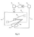
- the processing unit 14 can also be adapted to calculate a movement path 66 for a moving apparatus 68, which movement path is located inside the 3D free space model 32 (see also Fig. 5 ).
- the moving apparatus 68 is only schematically illustrated in a very simplified manner.
- the detection system 12 detects the dotted outer frame 32 as areas in which free space is available for movement such that this free space can be generated as the 3D free space model 32.
- Only schematically indicated is, for example, an object line 70 on the left side of the drawing.
- the object 70 for example, is not in particular necessary for defining the 3D free space model. It is rather only necessary to detect certain areas with depth information representing free volume in which a movement can take place. Thus, for example on the right side of the figure, a respective object corresponding to the one on the left side is not shown. However, free space was only detected up to the particular boundary of the 3D free space model, and thus the 3D free space model only extends across the shown area. However, this does not mean that a particular object is actually being arranged here, it just means that this is the actual space free for movement.
- the interface unit 16 provides the respective information for the movement path 66 which is calculated by the processing unit 14 to the moving apparatus 68.
- the movement path 66 is provided in addition to the 3D free space model 32, which 3D free space model acts as a basis for the calculation of the movement path 66 itself.
- the 3D free space model 32 is not further shown in the calculation box as is the case in Fig. 1 .
- the provision of the movement path 66 is indicated with an arrow 72.
- the restriction device is indicated with reference numeral 74, arranged in parentheses.
- the restriction device 74 can be provided as an actual adaptable hardware component restricting the movement of respective parts, and as such acting as limit stops or catches.
- the restriction device 74 can also be provided in form of an electronic control device limiting movement commands sent to the movement components such that the commands only result in movements inside the 3D free space model.
- This can also be provided in form of software, such as a plug-in module for an existing movement control software.
- the 3D free space model can be provided to a movable arrangement, such as the moving apparatus 68, and an adaptable movement restriction device can be provided, which is not further shown, which restriction device is adapted to restrict the movement of the movable arrangement to movements inside the 3D free space model.
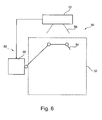
- Fig. 6 schematically describes an exemplary embodiment of a medical examination system 80 with motorized equipment according to the invention.
- the medical examination system 80 comprised a motorized functional system 82, and a medical safety-system 10 according to one of the above described embodiments.
- the motorized functional system 82 comprises a movable arrangement 84 to perform at least one task.
- An adaptable movement restriction device 86 is provided (not further shown), which is adapted to restrict the movement of the arrangement to movements inside the 3D free space model provided by the medical safety-system 10.
- the motorized functional system is shown with a three segments' movable arm structure as an example for illustrational purposes only.
- the medical safety-system 10 is shown in a simplified manner with a rectangular box only and with two dotted lines 88 indicating the above described detection of depth information. It must be noted that the medical safety-system 10 can be provided as any of the above described examples, or in a combination of two or more of the above described examples.
- the motorized functional system may be an image acquisition device with a movable arrangement to acquire image data of an object from different projections.
- a medical examination system with motorized equipment can for example be a robot in a healthcare environment with unknown objects which may have unknown movements, too. Without the medical safety system according to the invention, this would mostly result in collisions.
- a medical system with motorized equipment can be a C-arm arrangement or C-arch in an operation theatre in relation with medical interventions.
- the C-arch can collide with other equipments or with the staff members, such as the doctors performing an operation.
- a medical safety-system for example using time-of-flight cameras, is provided to find the free space in which the robot or the C-arch can move.
- Time-of-flight cameras can give depth information of the observed scene. By using multiple time-of-flight cameras in a scene and correlating the obtained depth information, the free space in the scene can be reconstructed, which finally can be converted into a 3D model of the free space. Using the information of the position of free spaces, movements with robotic arms or C-arches can be made in the observed scene, without colliding with any objects. Time-of-flight cameras also have the advantage that there is no limitation on the structure of the objects which surface is being detected, and they also work in real-time.
- a further advantage is that the system according to the invention also provides a corporation between the moving equipment and the fixed equipment in relation with the movable components of the system or motorized equipment, and also in relation with the user, moving in the scene.
- the movement of speed is also not limited, as is the case with, for example, capacitive and pressure sensors.
- time-of-flight cameras In case of using an infrared light for time-of-flight cameras, the system operates independently of light conditions. Further, since time-of-flight cameras are capable of capturing depth of at least 25 frames per second, it is possible to provide real-time 3D reconstruction.
- a further advantage is that, according to the inventive system, no object information is needed; the system does in particular not need any information about the volume of an object.
- the sensors can be freely arranged in the surrounding of the operation site, a large visible range with respect to detection of free space is provided. Therewith, path planning of larger path distances is possible, since the operation is not limited to a line of sight of a robot, for example. In case of the plurality of sensors, the system can look around objects and calculate a valid path even for those areas which, from the point of view of a robot, are not visible in the beginning of the path.
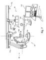
- Fig. 7 shows an example for an examination system 90, for example for an operation theatre in a hospital.
- the motorized functional system is an image acquisition arrangement 92 with a movable arrangement 94 to acquire image data of an object 96, for example a patient, from different projections.
- the image acquisition arrangement 92 comprises a C-arm structure 98 with an X-ray source 100 and an X-ray detector 102 arranged on opposing ends of the C-arm structure.
- the movement possibilities of the C-arm structure are limited to the 3D free space model 32, which is not further shown in Fig. 7 .
- a patient table 104 is shown to support the object of interest 96. Still further, a display arrangement 106 is shown in the vicinity of the table 104 as well as a lighting device 108. Further, a control station 110 is indicated in the foreground with displays and interface devices for controlling the examination system 90.
- a medical safety-system according to one of the above described examples is provided, of which only the sensors are shown as a plurality of sensors 112 arranged above and at the sides of the examination table 104.
- the sensors provide depth information of at least a part of the observed scene.
- the processing unit of the detection system can be provided in an integrated manner with the control station 110 of the examination system 90.
- a number of the sensors, indicated with index f is shown in a fixedly arranged manner at fixed points in the area of the ceiling.
- movable detectors indicated with index m are provided, for example on moving parts such as the C-arm or the display arrangement. They also provide depth information, however in combination with their current situation in space, which is provided, for example, by position detection systems which are arranged anyway in order to provide information about the current status of the C-arm, or also the display arrangement.
- the 3D free space model is generated as described above and then supplied to the C-arm structure.
- the movement possibilities of the C-arm structure are limited to the 3D free space model in order to avoid collision of the C-arm structure with any of the above described components.
- the update can be provided continuously or with a predetermined time interval.
- the update can also be triggered manually.
- the 3D free space model can be used, for example, for determining a movement path in space, such as when acquiring three-dimensional X-ray image information from a patient 96.
- the 3D free space model can be used also for a free movement of the C-arm structure, for example by an operational staff, for example a surgeon, trying to find a specific view of a patient. Therefore, the user can control the movement of the C-arm structure in a free manner, however, the movement is then automatically restricted to the available space in form of the 3D free space model.
- the user is provided with a facilitated way of handling the C-arm, since it is no longer necessary to especially look for possible collision situations. Rather, the user can move the C-arm as he or she wants, since it is assured that a collision is avoided, due to limiting the movement possibilities to the generated 3D free space model.
- restriction of the movement possibilities can be provided, as mentioned above, in form of hardware components, actually limiting the movement, or in form of software means, restricting the respective movement commands to lie inside the 3D free space model.
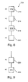
- Fig. 8 schematically describes a method 200 for providing safe movements in dynamic 3D healthcare environments.
- the following steps are provided:
- depth information 212 of at least a part of an observed scene is provided.
- the depth information is correlated.
- a generation step 216 a 3D free space model 218 is generated.
- the 3D free space model 218 is provided. It is noted that above, the 3D free space model 218 has also been referred to with reference numeral 32.
- the first provision step 210 is also referred to as step a), the correlation step 214 as step b), the generation step 216 as step c), and the second provision step 220 as step d).
- the 3D free space model 218 can be provided to a movable arrangement, and the movable arrangement can then move freely within the 3D free space model.
- a step e) is provided as calculation step 222, in which a movement path 224 of a movable arrangement is calculated to be positioned inside the 3D free space model 218.
- the movement path 224 may be, for example, the movement path 66 in Fig. 5 .
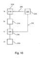
- Fig. 10 shows a further exemplary embodiment of the method according to the invention, in which depth information is provided as temporal depth information 212t, wherein the provision step is indicated with reference numeral 210t.
- a time signal 226 is provided by a time provision sub-step 228.
- the time signal 226 can be provided directly to the first provision step 210t, as indicated with first provision arrow 230 in a straight line.
- step b) comprises the correlation of the temporal depth information, which is why the correlation step is indicated with reference numeral 214t.
- step c) a 4D free space model 234 is generated, i.e. the step c) is a temporal generation step 236.
- the 4D free space model 234 is then provided in a provision step, referred to as provision step 220t.
- step c) i.e. in the generation step 236, the above mentioned steps a) and b) are of course referred to as provision step 210 and correlation step 214, i.e. without the index t.
- the term "healthcare” relates to all fields in which medical examination, medical treatment, medical intervention and the like are provided, for example in hospitals, doctor's practice etc.. Healthcare relates also to diagnostic, as well as to the treatment and the prevention of injury, disease, or illness.
- the term “medical” defines the relation to the field of medicine.
- a computer program or a computer program element is provided that is characterized by being adapted to execute the method steps of the method according to one of the preceding embodiments, on an appropriate system.
- the computer program element might therefore be stored on a computer unit, which might also be part of an embodiment of the present invention.
- This computing unit may be adapted to perform or induce a performing of the steps of the method described above. Moreover, it may be adapted to operate the components of the above described apparatus.
- the computing unit can be adapted to operate automatically and/or to execute the orders of a user.
- a computer program may be loaded into a working memory of a data processor.
- the data processor may thus be equipped to carry out the method of the invention.
- This exemplary embodiment of the invention covers both, a computer program that right from the beginning uses the invention and a computer program that by means of an up-date turns an existing program into a program that uses the invention.
- the computer program element might be able to provide all necessary steps to fulfil the procedure of an exemplary embodiment of the method as described above.
- a computer readable medium such as a CD-ROM
- the computer readable medium has a computer program element stored on it which computer program element is described by the preceding section.
- a computer program may be stored and/or distributed on a suitable medium, such as an optical storage medium or a solid state medium supplied together with or as part of other hardware, but may also be distributed in other forms, such as via the internet or other wired or wireless telecommunication systems.
- a suitable medium such as an optical storage medium or a solid state medium supplied together with or as part of other hardware, but may also be distributed in other forms, such as via the internet or other wired or wireless telecommunication systems.
- the computer program may also be presented over a network like the World Wide Web and can be downloaded into the working memory of a data processor from such a network.
- a medium for making a computer program element available for downloading is provided, which computer program element is arranged to perform a method according to one of the previously described embodiments of the invention.
Landscapes
- Engineering & Computer Science (AREA)
- Health & Medical Sciences (AREA)
- Life Sciences & Earth Sciences (AREA)
- Physics & Mathematics (AREA)
- Medical Informatics (AREA)
- General Physics & Mathematics (AREA)
- Veterinary Medicine (AREA)
- Animal Behavior & Ethology (AREA)
- Optics & Photonics (AREA)
- Pathology (AREA)
- Radiology & Medical Imaging (AREA)
- Biomedical Technology (AREA)
- Heart & Thoracic Surgery (AREA)
- Molecular Biology (AREA)
- Surgery (AREA)
- Biophysics (AREA)
- General Health & Medical Sciences (AREA)
- Public Health (AREA)
- High Energy & Nuclear Physics (AREA)
- Nuclear Medicine, Radiotherapy & Molecular Imaging (AREA)
- Automation & Control Theory (AREA)
- Human Computer Interaction (AREA)
- Manufacturing & Machinery (AREA)
- Computer Hardware Design (AREA)
- Mechanical Engineering (AREA)
- Computer Graphics (AREA)
- Robotics (AREA)
- General Engineering & Computer Science (AREA)
- Software Systems (AREA)
- Theoretical Computer Science (AREA)
- Signal Processing (AREA)
- Multimedia (AREA)
- Apparatus For Radiation Diagnosis (AREA)
- Image Processing (AREA)
- Measuring And Recording Apparatus For Diagnosis (AREA)
- Image Analysis (AREA)
Priority Applications (1)
| Application Number | Priority Date | Filing Date | Title |
|---|---|---|---|
| EP12715199.1A EP2695027B1 (en) | 2011-04-06 | 2012-03-30 | Safety in dynamic 3d healthcare environment |
Applications Claiming Priority (4)
| Application Number | Priority Date | Filing Date | Title |
|---|---|---|---|
| EP11305396 | 2011-04-06 | ||
| EP11305493 | 2011-04-27 | ||
| PCT/IB2012/051550 WO2012137116A1 (en) | 2011-04-06 | 2012-03-30 | Safety in dynamic 3d healthcare environment |
| EP12715199.1A EP2695027B1 (en) | 2011-04-06 | 2012-03-30 | Safety in dynamic 3d healthcare environment |
Publications (2)
| Publication Number | Publication Date |
|---|---|
| EP2695027A1 EP2695027A1 (en) | 2014-02-12 |
| EP2695027B1 true EP2695027B1 (en) | 2015-08-12 |
Family
ID=45976460
Family Applications (1)
| Application Number | Title | Priority Date | Filing Date |
|---|---|---|---|
| EP12715199.1A Active EP2695027B1 (en) | 2011-04-06 | 2012-03-30 | Safety in dynamic 3d healthcare environment |
Country Status (6)
| Country | Link |
|---|---|
| US (2) | US11372391B2 (enExample) |
| EP (1) | EP2695027B1 (enExample) |
| JP (1) | JP6499863B2 (enExample) |
| CN (1) | CN103582851B (enExample) |
| RU (1) | RU2013149272A (enExample) |
| WO (1) | WO2012137116A1 (enExample) |
Cited By (1)
| Publication number | Priority date | Publication date | Assignee | Title |
|---|---|---|---|---|
| US11953908B2 (en) | 2021-10-12 | 2024-04-09 | Google Llc | Deployable safety fence for mobile robots |
Families Citing this family (20)
| Publication number | Priority date | Publication date | Assignee | Title |
|---|---|---|---|---|
| DE102012208037A1 (de) * | 2012-05-14 | 2013-11-14 | Siemens Aktiengesellschaft | Patientenlagerungsvorrichtung, eine medizinischen Bildgebungsvorrichtung mit der Patientenlagerungsvorrichtung sowie ein Verfahren zu einer Markierung einer maximalen Aufenthaltsfläche |
| CN104936522B (zh) | 2013-01-17 | 2020-06-16 | 皇家飞利浦有限公司 | 天花板悬架系统 |
| KR20140141186A (ko) * | 2013-05-31 | 2014-12-10 | 삼성전자주식회사 | 엑스선 촬영 장치 및 그 제어 방법 |
| WO2015017639A1 (en) * | 2013-07-31 | 2015-02-05 | The Uab Research Foundation | Assessing machine trajectories for collision avoidance |
| US9348337B2 (en) * | 2014-05-14 | 2016-05-24 | Swissray Asia Healthcare Co., Ltd. | Environment recognition guide system for movable medical equipment and method |
| DE102015201070B4 (de) * | 2015-01-22 | 2020-04-23 | Siemens Healthcare Gmbh | Röntgenaufnahmesystem |
| CN105147311B (zh) * | 2015-08-12 | 2018-10-30 | 深圳安科高技术股份有限公司 | 用于ct系统中的可视化设备辅助扫描定位方法和系统 |
| CN110494900A (zh) * | 2017-02-07 | 2019-11-22 | 韦奥机器人股份有限公司 | 工作空间安全监控和设备控制 |
| US11820025B2 (en) | 2017-02-07 | 2023-11-21 | Veo Robotics, Inc. | Safe motion planning for machinery operation |
| DE102017214919A1 (de) * | 2017-08-25 | 2019-02-28 | Siemens Healthcare Gmbh | Bildgebende medizinische Einrichtung und Verfahren zum Betrieb einer bildgebenden medizinischen Einrichtung |
| EP3483839B1 (en) * | 2017-11-08 | 2025-09-10 | Siemens Healthineers AG | Dynamic generation of a medical scene model |
| US11114199B2 (en) | 2018-01-25 | 2021-09-07 | Mako Surgical Corp. | Workflow systems and methods for enhancing collaboration between participants in a surgical procedure |
| US11407111B2 (en) * | 2018-06-27 | 2022-08-09 | Abb Schweiz Ag | Method and system to generate a 3D model for a robot scene |
| EP3662834A1 (en) * | 2018-12-07 | 2020-06-10 | Koninklijke Philips N.V. | Positioning a medical x-ray imaging apparatus |
| EP3693137A1 (de) * | 2019-02-05 | 2020-08-12 | Siemens Healthcare GmbH | Verfahren zum herstellen eines pfadplanungsmoduls und zum betreiben eines roboters, pfadplanungsmodul und roboter |
| EP4034350A1 (en) * | 2019-09-26 | 2022-08-03 | Auris Health, Inc. | Systems and methods for collision avoidance using object models |
| EP4034349A1 (en) | 2019-09-26 | 2022-08-03 | Auris Health, Inc. | Systems and methods for collision detection and avoidance |
| JP7314091B2 (ja) | 2020-03-31 | 2023-07-25 | 富士フイルム株式会社 | 情報処理装置、情報処理方法、及び情報処理プログラム |
| CN112168192A (zh) * | 2020-09-30 | 2021-01-05 | 上海联影医疗科技股份有限公司 | 一种医学设备的运动控制方法及系统 |
| CN116548988B (zh) * | 2022-01-28 | 2025-11-28 | 上海西门子医疗器械有限公司 | 一种x射线成像中定位可运动部件的方法和装置 |
Family Cites Families (24)
| Publication number | Priority date | Publication date | Assignee | Title |
|---|---|---|---|---|
| SE456048B (sv) | 1982-02-24 | 1988-08-29 | Philips Norden Ab | Sett och anordning for att bestemma kollisionsrisken for tva inbordes rorliga kroppar |
| US5050204A (en) * | 1989-05-04 | 1991-09-17 | Siczek Bernard W | C-arm diagnostic equipment |
| US5325468A (en) * | 1990-10-31 | 1994-06-28 | Sanyo Electric Co., Ltd. | Operation planning system for robot |
| US5485502A (en) * | 1994-07-26 | 1996-01-16 | Lunar Corporation | Radiographic gantry with software collision avoidance |
| DE29724767U1 (de) * | 1997-10-01 | 2004-01-08 | Siemens Ag | Medizinische Einrichtung mit einer Vorrichtung zum Erfassen der Position zumindest eines sich in einem Raum befindenden Objektes |
| US7149262B1 (en) * | 2000-07-06 | 2006-12-12 | The Trustees Of Columbia University In The City Of New York | Method and apparatus for enhancing data resolution |
| JP4355341B2 (ja) | 2003-05-29 | 2009-10-28 | 本田技研工業株式会社 | 深度データを用いたビジュアルトラッキング |
| US10354224B2 (en) | 2003-11-07 | 2019-07-16 | Sysmex Corporation | Clinical laboratory systems, methods and computer programs for managing clinical laboratory work, management devices, and terminal devices |
| EP2273449A3 (en) * | 2004-06-11 | 2012-07-25 | Lyyn Ab | Method and Apparatus for Image Processing using Histogram Equalization |
| WO2006013829A1 (ja) * | 2004-08-02 | 2006-02-09 | Matsushita Electric Industrial Co., Ltd. | 物品運搬用ロボット、物品運搬システム、及び物品運搬方法 |
| DE102005009437A1 (de) | 2005-03-02 | 2006-09-07 | Kuka Roboter Gmbh | Verfahren und Vorrichtung zum Einblenden von AR-Objekten |
| EP1717757A1 (de) * | 2005-04-28 | 2006-11-02 | Bayerische Motoren Werke Aktiengesellschaft | Verfahren zur grafischen Darstellung der Umgebung eines Kraftfahrzeugs |
| US8384763B2 (en) * | 2005-07-26 | 2013-02-26 | Her Majesty the Queen in right of Canada as represented by the Minster of Industry, Through the Communications Research Centre Canada | Generating a depth map from a two-dimensional source image for stereoscopic and multiview imaging |
| JP4506685B2 (ja) * | 2006-02-17 | 2010-07-21 | トヨタ自動車株式会社 | 移動型ロボット |
| US9084622B2 (en) * | 2006-08-02 | 2015-07-21 | Omnitek Partners Llc | Automated laser-treatment system with real-time integrated 3D vision system for laser debridement and the like |
| DE102007013299A1 (de) * | 2007-03-06 | 2008-09-11 | Cedes Ag | Sensorvorrichtung sowie Anlage mit einem Förderer und einer Sensorvorrichtung |
| JP4576445B2 (ja) | 2007-04-12 | 2010-11-10 | パナソニック株式会社 | 自律移動型装置および自律移動型装置用プログラム |
| CN201060195Y (zh) * | 2007-07-31 | 2008-05-14 | 天津九安医疗电子股份有限公司 | 女性生理状态电子检测仪 |
| ITVI20070299A1 (it) * | 2007-11-14 | 2009-05-15 | Antoine Assaf | Apparato e metodo per il rilevamento di tessuti adiposi. |
| US20100091909A1 (en) | 2008-10-10 | 2010-04-15 | Harris Corporation | Systems and methods for unequal error protection and soft decision calculations |
| CN101518661B (zh) * | 2009-04-03 | 2013-02-27 | 北京工业大学 | 基于生理信号的心室辅助系统 |
| CN102460205A (zh) | 2009-06-23 | 2012-05-16 | 皇家飞利浦电子股份有限公司 | 位置确定系统 |
| US8918209B2 (en) * | 2010-05-20 | 2014-12-23 | Irobot Corporation | Mobile human interface robot |
| US8570320B2 (en) * | 2011-01-31 | 2013-10-29 | Microsoft Corporation | Using a three-dimensional environment model in gameplay |
-
2012
- 2012-03-30 RU RU2013149272/08A patent/RU2013149272A/ru unknown
- 2012-03-30 CN CN201280027727.8A patent/CN103582851B/zh active Active
- 2012-03-30 EP EP12715199.1A patent/EP2695027B1/en active Active
- 2012-03-30 WO PCT/IB2012/051550 patent/WO2012137116A1/en not_active Ceased
- 2012-03-30 JP JP2014503249A patent/JP6499863B2/ja active Active
- 2012-03-30 US US14/007,654 patent/US11372391B2/en active Active
-
2022
- 2022-05-23 US US17/750,588 patent/US12085915B2/en active Active
Cited By (1)
| Publication number | Priority date | Publication date | Assignee | Title |
|---|---|---|---|---|
| US11953908B2 (en) | 2021-10-12 | 2024-04-09 | Google Llc | Deployable safety fence for mobile robots |
Also Published As
| Publication number | Publication date |
|---|---|
| US11372391B2 (en) | 2022-06-28 |
| JP2014511731A (ja) | 2014-05-19 |
| RU2013149272A (ru) | 2015-05-20 |
| WO2012137116A1 (en) | 2012-10-11 |
| CN103582851B (zh) | 2016-05-11 |
| EP2695027A1 (en) | 2014-02-12 |
| JP6499863B2 (ja) | 2019-04-10 |
| US20220283563A1 (en) | 2022-09-08 |
| US12085915B2 (en) | 2024-09-10 |
| CN103582851A (zh) | 2014-02-12 |
| US20140022353A1 (en) | 2014-01-23 |
Similar Documents
| Publication | Publication Date | Title |
|---|---|---|
| US12085915B2 (en) | Safety in dynamic 3D healthcare environment | |
| US9795357B2 (en) | Positioning distance control for X-ray imaging systems | |
| CN110650704B (zh) | 用于检测图像捕获装置的视野内的物体的系统和方法 | |
| EP2887876B1 (en) | Patient-specific and automatic x-ray system adjustment based on optical 3d scene detection and interpretation | |
| EP2831841B1 (en) | Multicamera tracking | |
| JP2021007739A (ja) | 医用イメージングシステムにおいて対象3dポイントクラウドを生成するための方法及びシステム | |
| US20240389966A1 (en) | Interventional system | |
| US20190139300A1 (en) | Medical scene model | |
| JPWO2013141155A1 (ja) | 画像内遮蔽領域の画像補完システム、画像処理装置及びそのプログラム | |
| EP3086734A2 (en) | Object tracking device | |
| US20140301625A1 (en) | Image processing apparatus and radiographic apparatus having the same | |
| EP3854307A1 (en) | Skin dose mapping | |
| CN116350359A (zh) | 引导影像设备的位置调整的方法、存储介质及医疗系统 | |
| EP4593712B1 (en) | Medical device movement control apparatus | |
| EP4480421A1 (en) | Radiation information for a current situation | |
| CA3063693C (en) | Systems and methods for detection of objects within a field of view of an image capture device | |
| Cardan | Consumer-Grade Cameras and Other Approaches to Surface Imaging | |
| WO2015091159A2 (en) | Method and imaging system for combined x-ray and optical three-dimensional modeling of at least one interventional device | |
| WO2020240653A1 (ja) | X線撮影装置およびx線撮影装置の障害物接触回避方法 |
Legal Events
| Date | Code | Title | Description |
|---|---|---|---|
| PUAI | Public reference made under article 153(3) epc to a published international application that has entered the european phase |
Free format text: ORIGINAL CODE: 0009012 |
|
| 17P | Request for examination filed |
Effective date: 20131106 |
|
| AK | Designated contracting states |
Kind code of ref document: A1 Designated state(s): AL AT BE BG CH CY CZ DE DK EE ES FI FR GB GR HR HU IE IS IT LI LT LU LV MC MK MT NL NO PL PT RO RS SE SI SK SM TR |
|
| DAX | Request for extension of the european patent (deleted) | ||
| GRAP | Despatch of communication of intention to grant a patent |
Free format text: ORIGINAL CODE: EPIDOSNIGR1 |
|
| RIC1 | Information provided on ipc code assigned before grant |
Ipc: H04N 7/18 20060101ALI20150217BHEP Ipc: G06T 17/00 20060101ALI20150217BHEP Ipc: A61B 6/10 20060101ALI20150217BHEP Ipc: B25J 9/16 20060101ALI20150217BHEP Ipc: G05B 19/406 20060101AFI20150217BHEP Ipc: G05B 19/4061 20060101ALI20150217BHEP Ipc: A61B 6/00 20060101ALI20150217BHEP Ipc: G06T 19/00 20110101ALI20150217BHEP |
|
| INTG | Intention to grant announced |
Effective date: 20150305 |
|
| GRAS | Grant fee paid |
Free format text: ORIGINAL CODE: EPIDOSNIGR3 |
|
| GRAA | (expected) grant |
Free format text: ORIGINAL CODE: 0009210 |
|
| AK | Designated contracting states |
Kind code of ref document: B1 Designated state(s): AL AT BE BG CH CY CZ DE DK EE ES FI FR GB GR HR HU IE IS IT LI LT LU LV MC MK MT NL NO PL PT RO RS SE SI SK SM TR |
|
| REG | Reference to a national code |
Ref country code: GB Ref legal event code: FG4D |
|
| REG | Reference to a national code |
Ref country code: CH Ref legal event code: EP |
|
| REG | Reference to a national code |
Ref country code: AT Ref legal event code: REF Ref document number: 742681 Country of ref document: AT Kind code of ref document: T Effective date: 20150815 |
|
| REG | Reference to a national code |
Ref country code: IE Ref legal event code: FG4D |
|
| REG | Reference to a national code |
Ref country code: DE Ref legal event code: R096 Ref document number: 602012009535 Country of ref document: DE |
|
| REG | Reference to a national code |
Ref country code: LT Ref legal event code: MG4D |
|
| REG | Reference to a national code |
Ref country code: AT Ref legal event code: MK05 Ref document number: 742681 Country of ref document: AT Kind code of ref document: T Effective date: 20150812 |
|
| REG | Reference to a national code |
Ref country code: NL Ref legal event code: MP Effective date: 20150812 |
|
| PG25 | Lapsed in a contracting state [announced via postgrant information from national office to epo] |
Ref country code: LV Free format text: LAPSE BECAUSE OF FAILURE TO SUBMIT A TRANSLATION OF THE DESCRIPTION OR TO PAY THE FEE WITHIN THE PRESCRIBED TIME-LIMIT Effective date: 20150812 Ref country code: GR Free format text: LAPSE BECAUSE OF FAILURE TO SUBMIT A TRANSLATION OF THE DESCRIPTION OR TO PAY THE FEE WITHIN THE PRESCRIBED TIME-LIMIT Effective date: 20151113 Ref country code: NO Free format text: LAPSE BECAUSE OF FAILURE TO SUBMIT A TRANSLATION OF THE DESCRIPTION OR TO PAY THE FEE WITHIN THE PRESCRIBED TIME-LIMIT Effective date: 20151112 Ref country code: FI Free format text: LAPSE BECAUSE OF FAILURE TO SUBMIT A TRANSLATION OF THE DESCRIPTION OR TO PAY THE FEE WITHIN THE PRESCRIBED TIME-LIMIT Effective date: 20150812 Ref country code: LT Free format text: LAPSE BECAUSE OF FAILURE TO SUBMIT A TRANSLATION OF THE DESCRIPTION OR TO PAY THE FEE WITHIN THE PRESCRIBED TIME-LIMIT Effective date: 20150812 |
|
| PG25 | Lapsed in a contracting state [announced via postgrant information from national office to epo] |
Ref country code: RS Free format text: LAPSE BECAUSE OF FAILURE TO SUBMIT A TRANSLATION OF THE DESCRIPTION OR TO PAY THE FEE WITHIN THE PRESCRIBED TIME-LIMIT Effective date: 20150812 Ref country code: PT Free format text: LAPSE BECAUSE OF FAILURE TO SUBMIT A TRANSLATION OF THE DESCRIPTION OR TO PAY THE FEE WITHIN THE PRESCRIBED TIME-LIMIT Effective date: 20151214 Ref country code: AT Free format text: LAPSE BECAUSE OF FAILURE TO SUBMIT A TRANSLATION OF THE DESCRIPTION OR TO PAY THE FEE WITHIN THE PRESCRIBED TIME-LIMIT Effective date: 20150812 Ref country code: ES Free format text: LAPSE BECAUSE OF FAILURE TO SUBMIT A TRANSLATION OF THE DESCRIPTION OR TO PAY THE FEE WITHIN THE PRESCRIBED TIME-LIMIT Effective date: 20150812 Ref country code: PL Free format text: LAPSE BECAUSE OF FAILURE TO SUBMIT A TRANSLATION OF THE DESCRIPTION OR TO PAY THE FEE WITHIN THE PRESCRIBED TIME-LIMIT Effective date: 20150812 Ref country code: IS Free format text: LAPSE BECAUSE OF FAILURE TO SUBMIT A TRANSLATION OF THE DESCRIPTION OR TO PAY THE FEE WITHIN THE PRESCRIBED TIME-LIMIT Effective date: 20151212 Ref country code: SE Free format text: LAPSE BECAUSE OF FAILURE TO SUBMIT A TRANSLATION OF THE DESCRIPTION OR TO PAY THE FEE WITHIN THE PRESCRIBED TIME-LIMIT Effective date: 20150812 Ref country code: HR Free format text: LAPSE BECAUSE OF FAILURE TO SUBMIT A TRANSLATION OF THE DESCRIPTION OR TO PAY THE FEE WITHIN THE PRESCRIBED TIME-LIMIT Effective date: 20150812 |
|
| PG25 | Lapsed in a contracting state [announced via postgrant information from national office to epo] |
Ref country code: NL Free format text: LAPSE BECAUSE OF FAILURE TO SUBMIT A TRANSLATION OF THE DESCRIPTION OR TO PAY THE FEE WITHIN THE PRESCRIBED TIME-LIMIT Effective date: 20150812 |
|
| REG | Reference to a national code |
Ref country code: FR Ref legal event code: PLFP Year of fee payment: 5 |
|
| PG25 | Lapsed in a contracting state [announced via postgrant information from national office to epo] |
Ref country code: CZ Free format text: LAPSE BECAUSE OF FAILURE TO SUBMIT A TRANSLATION OF THE DESCRIPTION OR TO PAY THE FEE WITHIN THE PRESCRIBED TIME-LIMIT Effective date: 20150812 Ref country code: SK Free format text: LAPSE BECAUSE OF FAILURE TO SUBMIT A TRANSLATION OF THE DESCRIPTION OR TO PAY THE FEE WITHIN THE PRESCRIBED TIME-LIMIT Effective date: 20150812 Ref country code: DK Free format text: LAPSE BECAUSE OF FAILURE TO SUBMIT A TRANSLATION OF THE DESCRIPTION OR TO PAY THE FEE WITHIN THE PRESCRIBED TIME-LIMIT Effective date: 20150812 Ref country code: IT Free format text: LAPSE BECAUSE OF FAILURE TO SUBMIT A TRANSLATION OF THE DESCRIPTION OR TO PAY THE FEE WITHIN THE PRESCRIBED TIME-LIMIT Effective date: 20150812 Ref country code: EE Free format text: LAPSE BECAUSE OF FAILURE TO SUBMIT A TRANSLATION OF THE DESCRIPTION OR TO PAY THE FEE WITHIN THE PRESCRIBED TIME-LIMIT Effective date: 20150812 |
|
| REG | Reference to a national code |
Ref country code: DE Ref legal event code: R097 Ref document number: 602012009535 Country of ref document: DE |
|
| PG25 | Lapsed in a contracting state [announced via postgrant information from national office to epo] |
Ref country code: RO Free format text: LAPSE BECAUSE OF FAILURE TO SUBMIT A TRANSLATION OF THE DESCRIPTION OR TO PAY THE FEE WITHIN THE PRESCRIBED TIME-LIMIT Effective date: 20150812 |
|
| PLBE | No opposition filed within time limit |
Free format text: ORIGINAL CODE: 0009261 |
|
| STAA | Information on the status of an ep patent application or granted ep patent |
Free format text: STATUS: NO OPPOSITION FILED WITHIN TIME LIMIT |
|
| 26N | No opposition filed |
Effective date: 20160513 |
|
| PG25 | Lapsed in a contracting state [announced via postgrant information from national office to epo] |
Ref country code: BE Free format text: LAPSE BECAUSE OF NON-PAYMENT OF DUE FEES Effective date: 20160331 Ref country code: SI Free format text: LAPSE BECAUSE OF FAILURE TO SUBMIT A TRANSLATION OF THE DESCRIPTION OR TO PAY THE FEE WITHIN THE PRESCRIBED TIME-LIMIT Effective date: 20150812 |
|
| PG25 | Lapsed in a contracting state [announced via postgrant information from national office to epo] |
Ref country code: MC Free format text: LAPSE BECAUSE OF FAILURE TO SUBMIT A TRANSLATION OF THE DESCRIPTION OR TO PAY THE FEE WITHIN THE PRESCRIBED TIME-LIMIT Effective date: 20150812 Ref country code: LU Free format text: LAPSE BECAUSE OF FAILURE TO SUBMIT A TRANSLATION OF THE DESCRIPTION OR TO PAY THE FEE WITHIN THE PRESCRIBED TIME-LIMIT Effective date: 20160330 |
|
| REG | Reference to a national code |
Ref country code: CH Ref legal event code: PL |
|
| GBPC | Gb: european patent ceased through non-payment of renewal fee |
Effective date: 20160330 |
|
| REG | Reference to a national code |
Ref country code: IE Ref legal event code: MM4A |
|
| PG25 | Lapsed in a contracting state [announced via postgrant information from national office to epo] |
Ref country code: BE Free format text: LAPSE BECAUSE OF FAILURE TO SUBMIT A TRANSLATION OF THE DESCRIPTION OR TO PAY THE FEE WITHIN THE PRESCRIBED TIME-LIMIT Effective date: 20150812 |
|
| PG25 | Lapsed in a contracting state [announced via postgrant information from national office to epo] |
Ref country code: LI Free format text: LAPSE BECAUSE OF NON-PAYMENT OF DUE FEES Effective date: 20160331 Ref country code: GB Free format text: LAPSE BECAUSE OF NON-PAYMENT OF DUE FEES Effective date: 20160330 Ref country code: CH Free format text: LAPSE BECAUSE OF NON-PAYMENT OF DUE FEES Effective date: 20160331 Ref country code: IE Free format text: LAPSE BECAUSE OF NON-PAYMENT OF DUE FEES Effective date: 20160330 |
|
| REG | Reference to a national code |
Ref country code: FR Ref legal event code: PLFP Year of fee payment: 6 |
|
| PG25 | Lapsed in a contracting state [announced via postgrant information from national office to epo] |
Ref country code: MT Free format text: LAPSE BECAUSE OF FAILURE TO SUBMIT A TRANSLATION OF THE DESCRIPTION OR TO PAY THE FEE WITHIN THE PRESCRIBED TIME-LIMIT Effective date: 20150812 |
|
| REG | Reference to a national code |
Ref country code: FR Ref legal event code: PLFP Year of fee payment: 7 |
|
| PG25 | Lapsed in a contracting state [announced via postgrant information from national office to epo] |
Ref country code: SM Free format text: LAPSE BECAUSE OF FAILURE TO SUBMIT A TRANSLATION OF THE DESCRIPTION OR TO PAY THE FEE WITHIN THE PRESCRIBED TIME-LIMIT Effective date: 20150812 Ref country code: CY Free format text: LAPSE BECAUSE OF FAILURE TO SUBMIT A TRANSLATION OF THE DESCRIPTION OR TO PAY THE FEE WITHIN THE PRESCRIBED TIME-LIMIT Effective date: 20150812 Ref country code: HU Free format text: LAPSE BECAUSE OF FAILURE TO SUBMIT A TRANSLATION OF THE DESCRIPTION OR TO PAY THE FEE WITHIN THE PRESCRIBED TIME-LIMIT; INVALID AB INITIO Effective date: 20120330 |
|
| PG25 | Lapsed in a contracting state [announced via postgrant information from national office to epo] |
Ref country code: MK Free format text: LAPSE BECAUSE OF FAILURE TO SUBMIT A TRANSLATION OF THE DESCRIPTION OR TO PAY THE FEE WITHIN THE PRESCRIBED TIME-LIMIT Effective date: 20150812 Ref country code: TR Free format text: LAPSE BECAUSE OF FAILURE TO SUBMIT A TRANSLATION OF THE DESCRIPTION OR TO PAY THE FEE WITHIN THE PRESCRIBED TIME-LIMIT Effective date: 20150812 Ref country code: MT Free format text: LAPSE BECAUSE OF FAILURE TO SUBMIT A TRANSLATION OF THE DESCRIPTION OR TO PAY THE FEE WITHIN THE PRESCRIBED TIME-LIMIT Effective date: 20160331 |
|
| PG25 | Lapsed in a contracting state [announced via postgrant information from national office to epo] |
Ref country code: BG Free format text: LAPSE BECAUSE OF FAILURE TO SUBMIT A TRANSLATION OF THE DESCRIPTION OR TO PAY THE FEE WITHIN THE PRESCRIBED TIME-LIMIT Effective date: 20150812 |
|
| PG25 | Lapsed in a contracting state [announced via postgrant information from national office to epo] |
Ref country code: AL Free format text: LAPSE BECAUSE OF FAILURE TO SUBMIT A TRANSLATION OF THE DESCRIPTION OR TO PAY THE FEE WITHIN THE PRESCRIBED TIME-LIMIT Effective date: 20150812 |
|
| PGFP | Annual fee paid to national office [announced via postgrant information from national office to epo] |
Ref country code: DE Payment date: 20260320 Year of fee payment: 15 |
|
| PGFP | Annual fee paid to national office [announced via postgrant information from national office to epo] |
Ref country code: FR Payment date: 20260323 Year of fee payment: 15 |