EP2694182B1 - Method and system for filtration and filtration cake layer formation - Google Patents
Method and system for filtration and filtration cake layer formation Download PDFInfo
- Publication number
- EP2694182B1 EP2694182B1 EP12713866.7A EP12713866A EP2694182B1 EP 2694182 B1 EP2694182 B1 EP 2694182B1 EP 12713866 A EP12713866 A EP 12713866A EP 2694182 B1 EP2694182 B1 EP 2694182B1
- Authority
- EP
- European Patent Office
- Prior art keywords
- filtration
- filtration cake
- activated sludge
- cake
- mixed liquor
- Prior art date
- Legal status (The legal status is an assumption and is not a legal conclusion. Google has not performed a legal analysis and makes no representation as to the accuracy of the status listed.)
- Active
Links
- 238000001914 filtration Methods 0.000 title claims description 279
- 238000000034 method Methods 0.000 title claims description 67
- 230000015572 biosynthetic process Effects 0.000 title description 2
- 239000010802 sludge Substances 0.000 claims description 125
- 239000002245 particle Substances 0.000 claims description 93
- 239000007788 liquid Substances 0.000 claims description 85
- 239000007787 solid Substances 0.000 claims description 49
- 239000006228 supernatant Substances 0.000 claims description 46
- 239000000706 filtrate Substances 0.000 claims description 40
- 230000008569 process Effects 0.000 claims description 36
- 238000000926 separation method Methods 0.000 claims description 26
- 125000004122 cyclic group Chemical group 0.000 claims description 3
- 238000011010 flushing procedure Methods 0.000 claims description 3
- 239000010842 industrial wastewater Substances 0.000 claims description 3
- 239000010841 municipal wastewater Substances 0.000 claims description 3
- 238000004065 wastewater treatment Methods 0.000 description 10
- 239000012528 membrane Substances 0.000 description 8
- 239000002028 Biomass Substances 0.000 description 7
- 230000009471 action Effects 0.000 description 7
- 239000000126 substance Substances 0.000 description 7
- 230000004907 flux Effects 0.000 description 6
- XLYOFNOQVPJJNP-UHFFFAOYSA-N water Substances O XLYOFNOQVPJJNP-UHFFFAOYSA-N 0.000 description 6
- 230000007246 mechanism Effects 0.000 description 5
- 241000894006 Bacteria Species 0.000 description 4
- 239000012530 fluid Substances 0.000 description 4
- 238000005273 aeration Methods 0.000 description 3
- 238000007906 compression Methods 0.000 description 3
- 230000008021 deposition Effects 0.000 description 3
- 238000009434 installation Methods 0.000 description 3
- 239000000203 mixture Substances 0.000 description 3
- 239000011148 porous material Substances 0.000 description 3
- 230000001105 regulatory effect Effects 0.000 description 3
- 238000011001 backwashing Methods 0.000 description 2
- 238000005119 centrifugation Methods 0.000 description 2
- 238000004140 cleaning Methods 0.000 description 2
- 230000006835 compression Effects 0.000 description 2
- 238000011118 depth filtration Methods 0.000 description 2
- 230000000694 effects Effects 0.000 description 2
- 239000007789 gas Substances 0.000 description 2
- 238000004519 manufacturing process Methods 0.000 description 2
- 239000000463 material Substances 0.000 description 2
- 238000005259 measurement Methods 0.000 description 2
- 230000002250 progressing effect Effects 0.000 description 2
- 238000005086 pumping Methods 0.000 description 2
- 238000007790 scraping Methods 0.000 description 2
- 238000000527 sonication Methods 0.000 description 2
- 238000001179 sorption measurement Methods 0.000 description 2
- 238000002604 ultrasonography Methods 0.000 description 2
- 238000011144 upstream manufacturing Methods 0.000 description 2
- OKTJSMMVPCPJKN-UHFFFAOYSA-N Carbon Chemical compound [C] OKTJSMMVPCPJKN-UHFFFAOYSA-N 0.000 description 1
- QVGXLLKOCUKJST-UHFFFAOYSA-N atomic oxygen Chemical compound [O] QVGXLLKOCUKJST-UHFFFAOYSA-N 0.000 description 1
- 230000001580 bacterial effect Effects 0.000 description 1
- 238000006065 biodegradation reaction Methods 0.000 description 1
- 239000010796 biological waste Substances 0.000 description 1
- 229910052799 carbon Inorganic materials 0.000 description 1
- 230000008859 change Effects 0.000 description 1
- 238000005352 clarification Methods 0.000 description 1
- 238000005345 coagulation Methods 0.000 description 1
- 230000015271 coagulation Effects 0.000 description 1
- 230000001276 controlling effect Effects 0.000 description 1
- 238000010908 decantation Methods 0.000 description 1
- 230000003247 decreasing effect Effects 0.000 description 1
- 238000011161 development Methods 0.000 description 1
- 230000018109 developmental process Effects 0.000 description 1
- 230000002255 enzymatic effect Effects 0.000 description 1
- 239000000835 fiber Substances 0.000 description 1
- 238000011049 filling Methods 0.000 description 1
- 238000005189 flocculation Methods 0.000 description 1
- 230000016615 flocculation Effects 0.000 description 1
- 239000003292 glue Substances 0.000 description 1
- 239000010954 inorganic particle Substances 0.000 description 1
- 230000014759 maintenance of location Effects 0.000 description 1
- 238000005374 membrane filtration Methods 0.000 description 1
- 239000002184 metal Substances 0.000 description 1
- 238000001471 micro-filtration Methods 0.000 description 1
- 230000000813 microbial effect Effects 0.000 description 1
- 239000004745 nonwoven fabric Substances 0.000 description 1
- 229910052760 oxygen Inorganic materials 0.000 description 1
- 239000001301 oxygen Substances 0.000 description 1
- 230000035515 penetration Effects 0.000 description 1
- 230000008929 regeneration Effects 0.000 description 1
- 238000011069 regeneration method Methods 0.000 description 1
- 229910001220 stainless steel Inorganic materials 0.000 description 1
- 239000010935 stainless steel Substances 0.000 description 1
- 230000008719 thickening Effects 0.000 description 1
- 238000000108 ultra-filtration Methods 0.000 description 1
- 239000011800 void material Substances 0.000 description 1
- 239000002351 wastewater Substances 0.000 description 1
- 239000002759 woven fabric Substances 0.000 description 1
Images


Classifications
-
- C—CHEMISTRY; METALLURGY
- C02—TREATMENT OF WATER, WASTE WATER, SEWAGE, OR SLUDGE
- C02F—TREATMENT OF WATER, WASTE WATER, SEWAGE, OR SLUDGE
- C02F3/00—Biological treatment of water, waste water, or sewage
- C02F3/006—Regulation methods for biological treatment
-
- B—PERFORMING OPERATIONS; TRANSPORTING
- B01—PHYSICAL OR CHEMICAL PROCESSES OR APPARATUS IN GENERAL
- B01D—SEPARATION
- B01D29/00—Filters with filtering elements stationary during filtration, e.g. pressure or suction filters, not covered by groups B01D24/00 - B01D27/00; Filtering elements therefor
- B01D29/01—Filters with filtering elements stationary during filtration, e.g. pressure or suction filters, not covered by groups B01D24/00 - B01D27/00; Filtering elements therefor with flat filtering elements
- B01D29/03—Filters with filtering elements stationary during filtration, e.g. pressure or suction filters, not covered by groups B01D24/00 - B01D27/00; Filtering elements therefor with flat filtering elements self-supporting
-
- B—PERFORMING OPERATIONS; TRANSPORTING
- B01—PHYSICAL OR CHEMICAL PROCESSES OR APPARATUS IN GENERAL
- B01D—SEPARATION
- B01D29/00—Filters with filtering elements stationary during filtration, e.g. pressure or suction filters, not covered by groups B01D24/00 - B01D27/00; Filtering elements therefor
- B01D29/62—Regenerating the filter material in the filter
- B01D29/64—Regenerating the filter material in the filter by scrapers, brushes, nozzles, or the like, acting on the cake side of the filtering element
-
- B—PERFORMING OPERATIONS; TRANSPORTING
- B01—PHYSICAL OR CHEMICAL PROCESSES OR APPARATUS IN GENERAL
- B01D—SEPARATION
- B01D29/00—Filters with filtering elements stationary during filtration, e.g. pressure or suction filters, not covered by groups B01D24/00 - B01D27/00; Filtering elements therefor
- B01D29/76—Handling the filter cake in the filter for purposes other than for regenerating
- B01D29/80—Handling the filter cake in the filter for purposes other than for regenerating for drying
- B01D29/82—Handling the filter cake in the filter for purposes other than for regenerating for drying by compression
-
- C—CHEMISTRY; METALLURGY
- C02—TREATMENT OF WATER, WASTE WATER, SEWAGE, OR SLUDGE
- C02F—TREATMENT OF WATER, WASTE WATER, SEWAGE, OR SLUDGE
- C02F3/00—Biological treatment of water, waste water, or sewage
- C02F3/02—Aerobic processes
- C02F3/12—Activated sludge processes
- C02F3/1205—Particular type of activated sludge processes
- C02F3/121—Multistep treatment
-
- C—CHEMISTRY; METALLURGY
- C02—TREATMENT OF WATER, WASTE WATER, SEWAGE, OR SLUDGE
- C02F—TREATMENT OF WATER, WASTE WATER, SEWAGE, OR SLUDGE
- C02F3/00—Biological treatment of water, waste water, or sewage
- C02F3/02—Aerobic processes
- C02F3/12—Activated sludge processes
- C02F3/1205—Particular type of activated sludge processes
- C02F3/1215—Combinations of activated sludge treatment with precipitation, flocculation, coagulation and separation of phosphates
-
- C—CHEMISTRY; METALLURGY
- C02—TREATMENT OF WATER, WASTE WATER, SEWAGE, OR SLUDGE
- C02F—TREATMENT OF WATER, WASTE WATER, SEWAGE, OR SLUDGE
- C02F2209/00—Controlling or monitoring parameters in water treatment
- C02F2209/03—Pressure
-
- C—CHEMISTRY; METALLURGY
- C02—TREATMENT OF WATER, WASTE WATER, SEWAGE, OR SLUDGE
- C02F—TREATMENT OF WATER, WASTE WATER, SEWAGE, OR SLUDGE
- C02F2209/00—Controlling or monitoring parameters in water treatment
- C02F2209/08—Chemical Oxygen Demand [COD]; Biological Oxygen Demand [BOD]
-
- C—CHEMISTRY; METALLURGY
- C02—TREATMENT OF WATER, WASTE WATER, SEWAGE, OR SLUDGE
- C02F—TREATMENT OF WATER, WASTE WATER, SEWAGE, OR SLUDGE
- C02F2209/00—Controlling or monitoring parameters in water treatment
- C02F2209/10—Solids, e.g. total solids [TS], total suspended solids [TSS] or volatile solids [VS]
-
- C—CHEMISTRY; METALLURGY
- C02—TREATMENT OF WATER, WASTE WATER, SEWAGE, OR SLUDGE
- C02F—TREATMENT OF WATER, WASTE WATER, SEWAGE, OR SLUDGE
- C02F2209/00—Controlling or monitoring parameters in water treatment
- C02F2209/11—Turbidity
-
- C—CHEMISTRY; METALLURGY
- C02—TREATMENT OF WATER, WASTE WATER, SEWAGE, OR SLUDGE
- C02F—TREATMENT OF WATER, WASTE WATER, SEWAGE, OR SLUDGE
- C02F2209/00—Controlling or monitoring parameters in water treatment
- C02F2209/20—Total organic carbon [TOC]
-
- C—CHEMISTRY; METALLURGY
- C02—TREATMENT OF WATER, WASTE WATER, SEWAGE, OR SLUDGE
- C02F—TREATMENT OF WATER, WASTE WATER, SEWAGE, OR SLUDGE
- C02F2209/00—Controlling or monitoring parameters in water treatment
- C02F2209/44—Time
-
- Y—GENERAL TAGGING OF NEW TECHNOLOGICAL DEVELOPMENTS; GENERAL TAGGING OF CROSS-SECTIONAL TECHNOLOGIES SPANNING OVER SEVERAL SECTIONS OF THE IPC; TECHNICAL SUBJECTS COVERED BY FORMER USPC CROSS-REFERENCE ART COLLECTIONS [XRACs] AND DIGESTS
- Y02—TECHNOLOGIES OR APPLICATIONS FOR MITIGATION OR ADAPTATION AGAINST CLIMATE CHANGE
- Y02W—CLIMATE CHANGE MITIGATION TECHNOLOGIES RELATED TO WASTEWATER TREATMENT OR WASTE MANAGEMENT
- Y02W10/00—Technologies for wastewater treatment
- Y02W10/10—Biological treatment of water, waste water, or sewage
Definitions
- the present invention relates to a method of filtering a feed and waste water treatment system using the filtration method.
- the method utilizes a filtration cake for the filtration, which filtration cake is formed by elements contained in a liquid having a different composition than the feed to the filtered.
- the invention relates in particular to a method for filtering a liquid containing solid particles of different sizes which utilizes a filtration cake formed at least partly and preferably only from particles contained in said liquid containing solid particles of different sizes.
- the particles of the filtration cake are deposited on a filtration cake support and the method involves separation of the liquid containing solid particles of different sizes into two fractions: one fraction containing solid particles above a certain size and one containing smaller particles, and filtering the fraction containing smaller particles through the filtration cake.
- the feed to be filtered is activated sludge supernatant and the filtration cake is formed from flocs of an activated sludge mixed liquor.
- filters in a waste water treatment process carried out in e.g. a Membrane Bio Reactor suffer from the drawbacks of fouling and clogging leading to limited and even no flow through the filters.
- Filtering is often provided by micro- or ultra-filtration membranes having very high production costs, and at the same time quite fragile filter designs.
- the high production costs stipulate regeneration of the membrane, which is provided by back-flushing, chemical or enzymatic cleaning.
- JP 2004167393 disclose a system in which a filter surface is exposed to gas bubbles by use of a diffuser arranged below a filter element to keep the filter elements clean.
- US2008/0087607A1 discloses an effluent treatment installation which can be used to improve the filtration capacity of membranes and to reduce water losses without increasing the floor area thereof.
- the invention comprises a pulsed sludge blanket settling tank containing membrane filtration modules which are submerged in or above the sludge blanket, and the system for extracting the treated effluents is connected upstream of said filtration modules.
- the invention also relates to a method for clarification by means of coagulation/flocculation/decantation and for filtration using said installation.
- a first aspect relates to a method for filtering a liquid containing solid particles of different sizes.
- the method utilizing a filtration cake formed only from particles contained in the liquid containing solid particles of different sizes and these solid particles are deposited on a filtration cake support being a porous member as a porous layer forming the filtration cake.
- the filtration cake and support allow liquid to flow through the filtration cake to provide a filtrate, and the method comprising establishment of the filtration cake (18), the establishment comprising providing
- Solid particles of different sizes is preferably used to mean particles of activated sludge mixed liquor which range in size from approximately 1 micrometer (single bacteria cells) to above 1 millimetre (aggregates of activated sludge flocs, large inorganic particles).
- the "size” is typically used in a manner being ordinary to definitions of particles' sizes, such as e.g. a diameter in a conventional manner such as a volume based particle size which equals the diameter of a sphere that has same volume as a given particle.
- “Particle” is preferably used to include activated sludge flocs and aggregates thereof and other solid elements present in a fluid.
- Solid is preferably used to mean a substance which is not a liquid or a gas.
- Porous preferably used to mean a property of a material that allows it to pass a fluid through, if a pressure difference is applied.
- a certain size is preferably used to mean the larger particles of activated sludge mixed liquor which settle significantly faster that the small particles found in the activated sludge supernatant.
- the limit of "a certain size” typically and preferably is defined by e.g. the separation technique, where the distinction is made between e.g. settling and unsettling particles, the limit may be preselected. A typical value for the limit may be 10 micrometers.
- Activated sludge floes is preferably used to mean microbial aggregates forming majority of activated sludge mixed liquor suspended solids.
- Activated sludge floes is also preferably used to mean bacterial aggregates constituting the settleable fraction of the activated sludge mixed liquor, made up by bacteria, protozoa and other particles held together (like glue) by extracellular polymeric substances produced by bacteria.
- Activated sludge mixed liquor is preferably used to mean mixture of activated sludge flocs and activated sludge supernatant present in the process tank or tanks of an installation performing wastewater treatment according to the activated sludge process.
- activated sludge mixed liqour is preferably a mixture of liquid, typically being water, and mass of biological flocs.
- Activated sludge supernatant is preferably used to mean the top fraction of the activated sludge mixed liquor remaining after settling of the activated sludge flocs, containing the unsettleable particles and few activated sludge flocs. The settling is typically and preferably carried out until a top fraction of activated sludge supernatant is distinct, such as visually distinct. Accordingly, Activated sludge supernatant is preferably the water phase resulting from settling, centrifugation or in general separation of activated sludge mixed liqour, by separating out e.g. flocs and/or other solid elements contained in the activated sludge mixed liquor. The separation provides an activated sludge mixed liquor bottom fraction, which can be characterised as having a higher concentration of flocs than the unseparated active sludge mixed liquor.
- Cake particle removal mechanism is preferably used to mean the mechanism of removing particles by the filtration cake.
- a filtration cake is typically composed of activated sludge flocs capable of removing the particles present in activated sludge supernatant through a process of depth filtration. Small particles from the activated sludge supernatant enter the porous filtration cake and get adsorbed to the surface of the activated sludge flocs forming the cake. Adsorption of these particles contributes to the decrease of the internal porosity of the filtration cake and therefore the increase of the pressure drop across the cake. The pressure drop across the cake is additionally increased by the progressing collapse of the filtration cake caused by the compressible nature of the activated sludge flocs (cf. also fig. 3 herein).
- the fraction comprising the smaller particles may preferably be activated sludge supernatant, and wherein the solid particles above a certain size may preferably be activated sludge flocs.
- the activated sludge mixed liquor may preferably be activated sludge mixed liquor from a biological waste water treatment process.
- the activated sludge supernatant may be provided by settling an activated sludge mixed liquor, preferably being biologically treated municipial or industrial waster water present in a system treating municipal or industrial wasterwaster.
- the filtration cake may be formed on a backing layer on the cake support.
- the backing layer may preferably comprise paper, a net or similar, having pore sizes allowing filtrate to pass through while allowing build-up of the filtration cake, and wherein the cake is removed together with the backing layer.
- Methods according to the present invention may further comprise removal of the filtration cake.
- Such removal may preferably comprise the step of providing a flow of liquid through the cake support directed towards the filtration cake (18) which in many cases removes the filtration cake from the cake support.
- the removal of filtration cake or residues thereof may further comprise removal mechanical actions such as scraping, a chemical action, a flow of air bubbles , thermal action, sonication with ultrasound or any other means designed to separate the cake from the support.
- Methods according to the invention may further comprise returning the removed filtration cake to a process tank containing activated sludge mixed liquor.
- Establishment of a filtration cake according to the present invention may further comprise flushing a region in front of the filtration cake by the fraction containing smaller particles thereby removing the liquid used during establishment of the filtration cake.
- the pressure difference across the filtration cake support and the flocs when deposited thereon during establishment of filtration cake may be below 1 bar, such as below 0.5 bar, or even lower than 0.1 bar, and even more preferably between 0 and 200 mbar.
- the pressure difference during the establishemt of filtration cake varies according to a specified profile, e.g. such that allows the flow across the filter support to be constant during cake establishment.
- the pressure difference during the establishemt of filtration cake may constant over time, or the flow of liquid through the filtration cake and filtration cake support during the establishemt of filtration cake is constant over time, or both flow and pressure change over time according to a predefined profile.
- the filtration cake may be defined to have been formed when the mass of solids per unit area of the cake support has reached a preselected level.
- the preselected level may be selected within 0.05 to 10 kg dry solids per square meter.
- the pressure difference across the filtration cake support and the flocs when deposited thereon during the establishiment of filtration cake is increased over time.
- the filtration cake is defined to have been formed, when the pressure difference has reached a preselected level.
- Preferred embodiments of the invention may further comprise determining one or more parameters, such as turbidity, suspended solids concentration, total bacteria count, total organic carbon concentration, chemical oxygen demand (COD) of the liquid having passed through the cake support and the filtration cake, the determining being done by measuring and/or calculating.
- determining one or more parameters such as turbidity, suspended solids concentration, total bacteria count, total organic carbon concentration, chemical oxygen demand (COD) of the liquid having passed through the cake support and the filtration cake, the determining being done by measuring and/or calculating.
- the method may further comprise capturing the filtration cake or the particles thereof after it has been used for filtering the fraction containing smaller solid particles.
- a filtration cake captured after it has been used represents dewatered sludge and the present invention thereby provides the effects of dewatering sludge and removing the used filtration cake from the wastewater treatment system as surplus activated sludge.
- the method of filtration comprises a cyclic repetition of
- the invention preferably relates to a filtration system comprising
- the system may further comprise a backing layer on the cake support, the backing layer preferably comprises paper, a net or similar, having pore sizes allowing filtrate to pass through while allowing build-up of the filtration cake.
- the activated sludge mixed liquor is separated into fractions: one fraction which is thickened activated sludge mixed liquor containing solid particles above a certain size and one is activated sludge supernatant containing smaller solid particles.
- these two fractions are the only two fractions into which the liquid is separated although the liqud may be separated into further fractions.
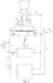
- Fig. 1 discloses in a schematical manner a waste water treatment system I.
- the system I comprises a process tank 1, a separation unit 2, a filtration unit 3 and a filtrate tank 7.
- Waste water such as municipal or industrial waste water, is treated biologically in the process tank 1 and activated sludge mixed liquor is thereby present in the tank 1.
- the activated sludge mixed liquor may flow to the separation unit 2 by use of the pump 9 in the liquid connection line 33 between the process tank 1 and the separation unit 2.
- the flow into the separation unit 2 may be cut off by use of the valve 12.
- the liquid connection line 33 comprising a bifurcation 34 with a liquid connection line 25 with shut off valve 16.
- the liquid connection line 25 enables activated sludge mixed liquor to flow to cavity 5 of the filtration unit 3 by use of the pump 9.
- Inflow of activated sludge mixed liquor to the filtration unit 3 may be cut off by use of the shut off valve 16.
- the separation unit 2 is typically embodied as a settling tank in which the activated sludge mixed liquor is separated by settling into activated sludge mixed liquor with a higher concentration of flocs and activated sludge supernatant above the activated sludge mixed liquor with higher concentration. It is noted that although the embodimement of fig. 1 uses a separation technique involving settling, other separation techniques, such as centrifugation, filtering or the like, may be applied.
- the embodiment disclosed in fig. 1 relates to an example where a liquid containing solid particles of different sizes is activated sludge mixed liquor being contained in the process tank. Further, the liquid containing solid particles of different sizes is separated into two fractions by the separation unit 2:
- the filtration unit 3 is embodied as a container having a filtration cake support 4 which divides the interior of the filtration unit 3 into a cavity 5 receiving activated sludge mixed liquor or activated sludge supernatant (via liquid connection line 31 as will be disclosed in details below), and a cavity 6 receiving filtrate through a filtration cake 18 formed on the filtration cake support 4. It is noted that the liquid passing through the cake support 4 and into the cavity 6 is termed filtrate irrespective of whether a filtration cake 18 is present on the cake support 4 or not. Pressure difference between the cavity 5 and cavity 6 may be measured by the pressure sensor 17.
- Filtration cake support 4 is a porous member in which the porosity is provided by a net supported by a frame or similar support structure to keep the net stretched.
- the net could be a frabric, wire mesh or similar which provides openings to allow liquid to pass through, while preventing flocs and/or particles from going through.
- the net has a mesh size sufficient to prevent particles and/or flocs of a certain size to pass through.
- the mesh size is preferably in the order of 1-100 micron times 1-100 micron and the net is preferably made as a woven or nonwoven fabric produced from paper, synthetic or natural fibers or metal, such as stainless steel mesh.
- the filtration cake support 4 may be provided by a structure with a coarse mesh and the mesh size being sufficient to prevent particles and/or flocs to go through is provided by arranging a backing layer on the coarse mesh structure.
- the backing layer preferably comprises paper, a net or similar, having pore sizes allowing filtrate to pass through while allowing build-up of the filtration cake.
- the outlet 13 is connected to the process tank 1 via liquid connection line 26 so that liquid may flow from the cavity 5 to the process tank 1.
- the outlet 14 is connected via liquid connection line 27 to a reservoir 20, typically being a reservoir for storing liquid, so that liquid may flow from the cavity 5 to the reservoir 20.
- a liquid connection line 28 between the cavity 6 and the filtrate tank 7 is provided.
- the liquid connection line 28 comprising a three way valve 15, whereby filtrate may flow from the cavity 6 to a three way valve 15 which leads the filtrate to either a filtrate tank 7 or back to the process tank 1 through liquid connection line 29 - the purpose of the three way 15 valve will be disclosed in further details below.
- the amount of filtrate flowing out of the filtrate unit 3 is detemined by the flow meter 21 and the turbidity of the filtrate is determined by the turbidity sensor 19. It is noted that the position of the flow meter 21 and the turbidity sensor 19 may be selected different from the indicated position in the liquid connection line 28 between the filtration unit 3 and the three way valve 15.
- the liquid connection line 28 further comprising a shut off valve 23 situated upstream of the three way valve 15 to prevent backflow, that is liquid flowing from the filtrate tank 7 or process tank 1 (via liquid connection line 29) to the cavity 6 of the filtration unit 3 through liquid connection line 28.
- the shut off valve 23 is a proportioning valve (or other kind of adjustable valve) and the control of its rate and extent of its opening is performed by the control system 8; the specific function of the proportioning valve 23 is typically exploided in the establishment of a filtration cake 18 when a constant flow or pressure profile is utilized as will be disclosed in further details below.
- the filtrate tank 7 comprises a liquid connection line 30 with a pump 11 between the filtrate tank 7 and the cavity 6 of the filtration unit 3 whereby filtrate in the filtrate tank 7 may flow to the cavity 6.
- the liquid connection line 30 further comprising a shut off valve 24 to avoid back flow, that is liquid flowing from the cavity 6 and to the filtrate tank 7 through liquid connection line 30. The purpose of moving filtrate back to the cavity 6 will be disclosed below.
- a liquid connection line 31 comprising a pump 10 is provided to feed supernatant or mixed liquor of higher concentration produced in the separation unit 2 into the cavity 5 of the filtration unit 3.
- the liquid connection line 31 further comprises a shut off valve 22 to prevent back flow, that is flow of liquid from the cavity 5 to separation unit 2 through the liquid connection line 31.
- a liquid connection line 32 is provided at an outlet of the separation unit 2 for outletting activated sludge mixed liquour contained in the separation unit 2.
- the liquid connection 32 connects the separation unit 2 with the process tank 1 so that activated sludge mixed liquor of higher concentration may flow to the process tank 1 through a separate liquid connection line (not shown in fig. 1 ) or by the liquid connection line 32 connecting an outlet of the separation unit for activated sludge mixed liquor with the liquid connection 29 as shown in fig. 1 .
- Thickening of the activated sludge supernatant in the separation unit 2 will take place and the liquid connection line 32 is typically designed to and performs transport of the thickened activated sludge mixed liquor back to the tank 1.
- This liquid is termed R eturn A ctivated S ludge mixed liquor (RAS).
- the liquid connection lines between the units are typically embodied as pipes and the flow of liquids between the units is controlled by a control system 8 controlling the operation of pumps 9, 10 and 11 and the valves 12, 13, 14 , 15, 16, 22, 23, 24.
- a control system 8 controlling the operation of pumps 9, 10 and 11 and the valves 12, 13, 14 , 15, 16, 22, 23, 24.
- readouts from the pressure sensor 17, the flow meter 21 and the turbidity sensor 19 is received by the control system 8 and used in the control of the system I.
- valve 16 in open state
- the valves are in the following states: Valve 12 13 14 15 16 22 23 24 State Closed Open Closed To 1 Open Closed Closed Closed
- valves provide a flow of of activated sludge mixed liquor into the cavity 5.
- the valves are arranged in the following states: Valve 12 13 14 15 16 22 23 24 State Closed Closed Closed To 1 Open Closed Regulated Closed
- Pump 9 pumps activated sludge mixed liquor from the process tank 1 into the cavity 5 and the only way to release the pressure is for the liquid to pass the cake support 4 and escape through the liquid connection line 28 and the valve 23. Flocs, which are sufficiently large to be entrapped on the cake support, form the filtration cake 18.
- the valve 23 can be 100% open and then the cake establishment proceeds according to the constant pressure mode, where the pressure is decided by pump 9.
- the valve can be regulated by the control system 8 based on the readings from the flowmeter 21, so that as the filtration cake 18 grows in thickness and creates more hydraulic resistance, the valve 23 gradually opens to maintain constant flow through the cake support 4. The process ends when the cake has achieved the desired thickness, indirectly indicated by the pressure sensor 17.
- valve 13 is opened and the excess activated sludge mixed liquor is pushed out of the cavity 5 by the inflow of supernatant to the cavity 5 through the valve 22 and liquid connection line 31 and back into the process tank 1.
- the valves are in the following states: Valve 12 13 14 15 16 22 23 24 State Open Open Closed To 1 Closed Open Closed Closed
- Filtration of activated sludge supernatant takes place by pumping activated sludge supernatant from the separation unit 2 and through the filtration cake 18 by means of pump 10.
- the quality of the filtrate is monitored by a turbidity sensor 19. If the quality is acceptable, typically meaning that the turbidity being smaller that a pre-set number, the filtrate is directed into the filtrate tank 7 through the 3-way valve 15. If the quality is not acceptable, the filtrate is directed to the process tank 1 through the 3-way valve 15.
- the valves are in the following states during filtration mode: Valve 12 13 14 15 16 22 23 24 State Open Closed Closed - Closed Open Open Closed
- the first regime of the exchange of filtration cake stage comprising removing the filtration cake 18 present on the filtration cake support 4. This is done by pumping filtrate from the filtrate tank 7 by use of pump 11 into cavity 6 of filtration unit 3.
- the valves are in the following states during this first regime: Valve 12 13 14 15 16 22 23 24 State Closed Open Closed To 7 Closed Closed Closed Open
- Filtrate is then pumped from the filtrate tank 7 through pump 11 and into the cavity 6 of the filtration unit 3 creating flow through and pressure difference across the filtration cake 18 and filtration cake support 4, separating the filtration cake from the filtration cake support 4.
- the released cake is then either flushed through valve 13 and back into the process tank 1 (as indicated in the above table) or through valve 14 into the reservoir for further treatment as surplus sludge.
- removal of the filtration cake 18 is typically carried out by what can be characterized as back washing including a reversed liquid flow as disclosed above.
- back washing including a reversed liquid flow as disclosed above.
- removal - or in combination thereto - filtration cake 18 or remaining elements thereof may be removed by mechanical actions such as scraping, a chemical action, a thermal action, sonication with ultrasound or other.
- the stage of establishment of a filtration cake 18 is executed out - as outlined above - resulting in that a new filtration cake is established on the filtration cake support 4.
- a filtration is typically carried out by a cyclic repetition of the stages: establishment of filtration cake, filtration of supernatant and removal of filtration cake.
- Fig. 2a and b each shows schematically profiles for pressure, P, across the filtration cake 18 (when present) and the cake support 4, flow, Q, through the filtration cake 18 (when present) and cake support 4 and filtration cake amount in terms of dry matter, ⁇ , (measured in kilograms of cake dry matter / unit area) (kg/m2).
- dry matter amount refers to the content of flocs deposited on the filtration cake support 4.
- Figure 2a shows profiles for constant pressure mode during establishment of filtration cake and figure 2b shows profiles for constant flow mode during establishment of filtration cake.
- the filtration cake dry matter amount ⁇ may be indirectly translated into the filtration cake thickness.
- Fig. 2a and b are just two examples, any combination in between is possible, in the sense that both pressure and flow can vary according to a specified profile.
- the volume flow, Q, of filtrate is decreasing as function of time during the establishment of filtration cake mode A.
- the pressure difference, P, across the filtration cake support 4 and the filtration cake 18 (when being established) is kept constant. This is due to the way the filtration cake is established namely by operating the pump 9 to fill the cavity 5 with activated sludge mixed liquor and feed of activated sludge supernatant into the cavity 5.
- the amounts of dry matter deposited on the filtration cake support 4 increases resulting in an increase in flow resistance in the filtration cake 18.
- the volume flow, Q drops over time.When the cake amount reaches a pre-defined level, the filtration cake establishment stage A is terminated and the filtration stage B initiated.
- the pump 10 is operated to provide a constant flow of mixed liquour supernatant to the cavity and thereby a constant flow of filtrate out of the the cavity 6.
- particles contained in the mixed liquour supernatant are filtered off in the filtration cake 18 and are deposited inside the filtration cake 18.
- the increasing clogging of the filtration cake 18 increases the pressure difference over of the filtration cake 18 with filtration cake support 4 which is shown in fig. 2a as an substantial increase in pressure P at the end of filtration mode B.
- the end of filtration mode B is typically selected to be when the pressure P reaches a certain predefined level.
- the removal of filtration cake C is initiated. This involves as disclosed above a reversal of the flow through the filtration cake support so that the filtration cake 18 is removed from the filtration cake support 4 by the action of the liquid flowing through the filtration cake support 4 from cavity 6 to cavity 5.
- this reversed flow is shown as a negative liquid flow Q, a reversed pressure difference and a decrease of dry matter ⁇ deposited on the filtration cake support 4. It is noted that in general, the dry matter amount deposited on the filtration cake support 4 is not determined by a direct measurement and the termination of the exchange of filtration cake C is performed when the pressure difference P reaches a certain level such as less than 10 mbar. It is important to notice that backwashing the cake is only one of many ways to remove the cake from the support and clean the support - any other technique can be applied.
- Fig. 2b shows similarly to fig. 2a the various stages A, B and C.
- the operation of the system in fig. 2b involves a constant flow rate during the establishment of filtration cake mode A.
- This constant flow rate is provided by operating the pump 9, so as to produce a gradually increasing pressure difference P as shown in fig. 2b , mode A. (or maintaining the constant speed of pump 9 and regulating the valve 23).
- the result compared to the embodiment of fig. 2a is that the increase rates of dry matter amount deposited on the filtration cake support 4 are different.
- the deposition rate changes as a function of time, whereas the deposition rate is virtually constant as function of time when the flow is kept constant ( fig. 2b ).
- the filtration mechanism is schematically disclosed as well as the clogging of the filtration cake 18.
- the dry matter, that is activated sludge flocs, deposited on the filtration cake support 4 is shown as larger elements 36 compared to smaller elements 37 contained in the activated sludge supernatant to be filtered through the filtration cake 18.
- the filtration cake 18 is a porous member some of the smaller particles will be trapped in the void left in between the flocs 36 and adsorbed to their surfaces, and some will go through the filtration cake 18. Ideally, all smaller particles will be trapped in the filtration cake.
- the amount of trapped particles 37 depends on the thickness of the filtration cake, as well as the porosity of the filtration cake 18 and may also depend on whether the filtration cake 18 is compressed or not; a compression of the filtration cake 18 may be performed by a increasing the pressure difference over the filtration cake and the filtration cake support.
- a filtration cake 18 composed of activated sludge flocs is capable of removing the particles present in activated sludge supernatant through a process of depth filtration.
- Small particles 37 from the activated sludge supernatant enter the porous filtration cake 18 and get adsorbed to the surface of the activated sludge flocs forming the filtration cake 18. Adsorption of these particles contributes to the decrease of the internal porosity of the filtration cake and therefore the increase of the pressure drop across the filtration cake 18.
- the pressure drop P across the filtration cake 18 is additionally increased by the progressing collapse of the filtration cake caused by the compressible nature of the activated sludge flocs.
- the quality of filtrate i.e. the concentration of particles in the filtrate, noted as Cf in figure 4
- the turbidity sensor is one way of achieving the online quality measurement.
- a constraint on the filtrate quality (maximum concentration of particles in the filtrate denoted by a horizontal dashed line in figure 4 ) can be set (e.g. as a turbidity less than 1 NTU, or as suspended solids concentration of less than 1 mg per liter), and a way to satisfy the constraint is to compress the cake according to a specific profile (gradually or step-wise) by increasing the flowrate through the filtration cake, which will result in gradual (or step-wise) increase in the pressure drop across the cake. This pressure drop increase will modify the filtration cake 18's porosity, and therefore its efficiency in removing the particles from the feed.
- the flowrate (flux) through the cake can be returned to the original value - the quality will remain higher due to the high degree of irreversibility of the compression process.
- the result will also be that the pressure drop through the cake will be higher than the original value, before the compression was made.
- An advangeous self-healing effect is presented by the method and system of the present invention. If during the establishment stage, a part of the filtration cake 18 is removed, falls off or otherwise no longer forming part of the filtration cake 18, a self-repairing mechanism takes place. If a part of the filtration cake 18 is missing, lack of flocs in that part of the filtration cake 18 results in that a local region of the filtration cake 18 with less hydraulic resistance is obtained tending to attract liquid with flocs to such region resulting in the flocs will deposit in the region thereby filling the region with flocs to re-establish the filtration cake 18.
- Such holes in the filtration cake will be sensed by the pressure sensor as a decrease in pressure drop between the two cavities 5 and 6 as well as an increased turbidity of the liquid measured by the turbidity sensor 19. If a large penetration is detected in the cake during operation (filtration stage), dosing of activated sludge mixed liquor may be performed to mend and complete the cake.
- Fig. 5 indicates an operation mode of a preferred embodiment of the invention.
- a filter that is a combination of a filtration cake support (4) and a filtration cake (18)
- a box with a line connecting two corners as used ordinary to a skilled person
- the filtration cake 18 is provided by activated sludge mixed liquor from process tank 1.
- Fig. 5 further comprises means for separating out flocs and/or other solid elements contained in the sludge before the activated sludge supernatant is displaced through the filtration cake 8.
- Fig. 5 indicates an operation mode in which formation of the filtration cake (18) is done via the activated sludge mixed liquor, that is the filtration cake 18 is made by deposition of particles on the filtration cake support (4) from the liquid to be filtered.
- the activated sludge mixed liquor is separated into two fractions: one fraction containing the mixed liquor of higher concentration labelled RAS ( R eturn A ctivated S ludge) and one fraction containing non-settling particles and treated water labelled activated sludge supernatant.
- RAS R eturn A ctivated S ludge
- activated sludge supernatant two fractions are provided: one fraction containing solid particles above certain size (RAS) and one containing smaller solid particles (activated sludge supernatant).
- RAS solid particles above certain size
- activated sludge supernatant For filtration, only activated sludge supernatant is moved through the filtration cake 18, while RAS is moved back to the region in
- the present invention furthermore provides the possibility of dewatering activated sludge in the filtration setup disclosed above.
- the valve 14 and the reservoir 20 of fig. 1 are designed inter alia to remove and capture the used filtration cake 18 which has been loaded with particles and compressed during operation.
- the filtration cake 18 is typically so compressed and solidified that its water content is similar to what can be achieved in sludge dewatering devices, such as belt presses, filter presses and centrifuges, whereby additional equipment for sludge dewatering may not be required in systems and methods according to the present invention if the used filtration cake is captured instead of feeding the material of the used filtration cake 18 to the process tank 1.
- the pressure difference across the filtration cake support 4 and the solid particles deposited thereon during establishment of the filtration cake 18 is typically between 0 and 200 mbar and the pressure difference across the filtration cake 18 and the filtration cake support 4 during operation is typically up to 200 mbar.
- the pressure levels is often setup limitations and may be different. However, pressure levels above 1 bar is at present not found reasonable.
- Fluxes flow of liquid through the filtration cake divided by the area of the filtration cake
- Fluxes are in the range of 100 to 2000-3000 LMH (liters per square meter per hour). It has been found that higher flux results in a shorter filtration cake lifetime (lifetime before clogging to an extend prompting exchange).
- Filtration cakes 18 usually live from 5-15 minutes (high fluxes, e.g. 1500-2000 LMH) to several hours (e.g. 5 hours at 300 LMH), but it has also been observed that it depends on sludge properties and the particle concentration in the supernatant.
- Figure 6 presents an exemplary cake filtration process run performed at the flux of 700 LMH (liters per square meter per hour).
- the cake filtration process run is carried out with the embodiment shown in fig. 1 .
- the turbidity of the filtrate was measured several times during the process in order to track the improving efficiency of the filtration cake in terms of particle removal and to demonstrate the quality of filtrate produced by the present invention.
- the process run was terminated when the pressure drop accros the filtration cake reached 40 mbar.
Description
- The present invention relates to a method of filtering a feed and waste water treatment system using the filtration method. The method utilizes a filtration cake for the filtration, which filtration cake is formed by elements contained in a liquid having a different composition than the feed to the filtered. The invention relates in particular to a method for filtering a liquid containing solid particles of different sizes which utilizes a filtration cake formed at least partly and preferably only from particles contained in said liquid containing solid particles of different sizes. The particles of the filtration cake are deposited on a filtration cake support and the method involves separation of the liquid containing solid particles of different sizes into two fractions: one fraction containing solid particles above a certain size and one containing smaller particles, and filtering the fraction containing smaller particles through the filtration cake. According to preferred aspects of the invention, the feed to be filtered is activated sludge supernatant and the filtration cake is formed from flocs of an activated sludge mixed liquor.
- It is well known that filters in a waste water treatment process carried out in e.g. a Membrane Bio Reactor (MBR) suffer from the drawbacks of fouling and clogging leading to limited and even no flow through the filters. Filtering is often provided by micro- or ultra-filtration membranes having very high production costs, and at the same time quite fragile filter designs. The high production costs stipulate regeneration of the membrane, which is provided by back-flushing, chemical or enzymatic cleaning.
- Recent developments (See e.g. Characteristics of a Self-Forming Dynamic Membrane Coupled with a Bioreactor for Municipal Waste water Treatment, Environ. Sci. Technol. 2002, 36, 5245-5251) suggest that the layer of biomass on a coarse mesh improves a solid-liquid separation. In the suggested method, the thickness of the biomass layer grows continuously during filtration. In order to control growth, bottom aeration is used to continuously lift some solids from the surface and the biomass layer and to keep the thickness more or less constant. Thickness of the fouling layer on the membrane depends on many factors: coarse bubble aeration rate, filter module geometry, sludge properties etc. so it is very hard to choose optimum conditions; in fact, the cake, or in general the biomass layer, forms more or less spontaneously, so its rejection capabilities are to a large extent undefined. Also, membrane coarse bubble aeration is one of the largest contributors to operating costs of an MBR, and membranes need chemical cleaning, which is both expensive and complicated.
- An example of such a waste water treatment system is disclosed in
JP 2004167393 - Another example of a waste water treatment system is disclosed in
US2008/0087607A1 which discloses an effluent treatment installation which can be used to improve the filtration capacity of membranes and to reduce water losses without increasing the floor area thereof. For said purpose, the invention comprises a pulsed sludge blanket settling tank containing membrane filtration modules which are submerged in or above the sludge blanket, and the system for extracting the treated effluents is connected upstream of said filtration modules. The invention also relates to a method for clarification by means of coagulation/flocculation/decantation and for filtration using said installation. - Hence, an improved means of achieving biomass retention in a waste water treatment process would be advantageous, and in particular a more efficient and/or reliable filtration would be advantageous.
- It is a further object of the present invention to provide an alternative to the prior art. In particular, it may be seen as an object of the present invention to provide devices, systems and methods that solve the above mentioned problems of the prior art with a new method for achieving membrane-quality filtration with compressed biomass.
- Thus, the above described object and several other objects are intended to be obtained by the various aspects of the invention which in a first aspect relates to a method for filtering a liquid containing solid particles of different sizes. The method utilizing a filtration cake formed only from particles contained in the liquid containing solid particles of different sizes and these solid particles are deposited on a filtration cake support being a porous member as a porous layer forming the filtration cake. The filtration cake and support allow liquid to flow through the filtration cake to provide a filtrate, and the method comprising establishment of the filtration cake (18), the establishment comprising providing
- a flow of liquid towards the filtration cake support (4), the liquid being the activated sludge mixed liquor containing solid particles of different sizes-ef,
- a pressure difference across the filtration cake support (4), to provide a flow of liquid through the filtration cake support (4);
until a filtration cake (18) has been formed - separating the liquid containing solid particles of different sizes into two fractions: one fraction containing solid particles above a certain size and one containing smaller solid particles, and
- providing a flow of the fraction comprising only the smaller particles towards and through the filtration cake (18) in a direction towards and through the cake support (4), thereby providing a filtering of the fraction containing smaller solid particles.
- In the present context, a number of terms are used in a manner being ordinary to the skilled person. However, some of these terms are explained below:
Solid particles of different sizes is preferably used to mean particles of activated sludge mixed liquor which range in size from approximately 1 micrometer (single bacteria cells) to above 1 millimetre (aggregates of activated sludge flocs, large inorganic particles). The "size" is typically used in a manner being ordinary to definitions of particles' sizes, such as e.g. a diameter in a conventional manner such as a volume based particle size which equals the diameter of a sphere that has same volume as a given particle. "Particle" is preferably used to include activated sludge flocs and aggregates thereof and other solid elements present in a fluid. Solid is preferably used to mean a substance which is not a liquid or a gas. - Porous preferably used to mean a property of a material that allows it to pass a fluid through, if a pressure difference is applied.
- Above a certain size is preferably used to mean the larger particles of activated sludge mixed liquor which settle significantly faster that the small particles found in the activated sludge supernatant. While the limit of "a certain size" typically and preferably is defined by e.g. the separation technique, where the distinction is made between e.g. settling and unsettling particles, the limit may be preselected. A typical value for the limit may be 10 micrometers.
- Activated sludge floes is preferably used to mean microbial aggregates forming majority of activated sludge mixed liquor suspended solids. In addition Activated sludge floes is also preferably used to mean bacterial aggregates constituting the settleable fraction of the activated sludge mixed liquor, made up by bacteria, protozoa and other particles held together (like glue) by extracellular polymeric substances produced by bacteria.
- Activated sludge mixed liquor is preferably used to mean mixture of activated sludge flocs and activated sludge supernatant present in the process tank or tanks of an installation performing wastewater treatment according to the activated sludge process. Accordingly, activated sludge mixed liqour is preferably a mixture of liquid, typically being water, and mass of biological flocs.
- Activated sludge supernatant is preferably used to mean the top fraction of the activated sludge mixed liquor remaining after settling of the activated sludge flocs, containing the unsettleable particles and few activated sludge flocs. The settling is typically and preferably carried out until a top fraction of activated sludge supernatant is distinct, such as visually distinct. Accordingly, Activated sludge supernatant is preferably the water phase resulting from settling, centrifugation or in general separation of activated sludge mixed liqour, by separating out e.g. flocs and/or other solid elements contained in the activated sludge mixed liquor. The separation provides an activated sludge mixed liquor bottom fraction, which can be characterised as having a higher concentration of flocs than the unseparated active sludge mixed liquor.
- Cake particle removal mechanism is preferably used to mean the mechanism of removing particles by the filtration cake. Such a filtration cake is typically composed of activated sludge flocs capable of removing the particles present in activated sludge supernatant through a process of depth filtration. Small particles from the activated sludge supernatant enter the porous filtration cake and get adsorbed to the surface of the activated sludge flocs forming the cake. Adsorption of these particles contributes to the decrease of the internal porosity of the filtration cake and therefore the increase of the pressure drop across the cake. The pressure drop across the cake is additionally increased by the progressing collapse of the filtration cake caused by the compressible nature of the activated sludge flocs (cf. also
fig. 3 herein). - The fraction comprising the smaller particles may preferably be activated sludge supernatant, and wherein the solid particles above a certain size may preferably be activated sludge flocs.
- In preferred embodiments, the activated sludge mixed liquor may preferably be activated sludge mixed liquor from a biological waste water treatment process.
- Further, the activated sludge supernatant may be provided by settling an activated sludge mixed liquor, preferably being biologically treated municipial or industrial waster water present in a system treating municipal or industrial wasterwaster.
- In preferred embodiments, the filtration cake may be formed on a backing layer on the cake support. The backing layer may preferably comprise paper, a net or similar, having pore sizes allowing filtrate to pass through while allowing build-up of the filtration cake, and wherein the cake is removed together with the backing layer.
- Methods according to the present invention may further comprise removal of the filtration cake. Such removal may preferably comprise the step of providing a flow of liquid through the cake support directed towards the filtration cake (18) which in many cases removes the filtration cake from the cake support.
- The removal of filtration cake or residues thereof may further comprise removal mechanical actions such as scraping, a chemical action, a flow of air bubbles , thermal action, sonication with ultrasound or any other means designed to separate the cake from the support.
- Methods according to the invention may further comprise returning the removed filtration cake to a process tank containing activated sludge mixed liquor.
- Establishment of a filtration cake according to the present invention may further comprise flushing a region in front of the filtration cake by the fraction containing smaller particles thereby removing the liquid used during establishment of the filtration cake.
- The pressure difference across the filtration cake support and the flocs when deposited thereon during establishment of filtration cake may be below 1 bar, such as below 0.5 bar, or even lower than 0.1 bar, and even more preferably between 0 and 200 mbar. In preferred embodiments of the invention, the pressure difference during the establishemt of filtration cake varies according to a specified profile, e.g. such that allows the flow across the filter support to be constant during cake establishment.
- According to preferred embodiments of the invention, the pressure difference during the establishemt of filtration cake may constant over time, or the flow of liquid through the filtration cake and filtration cake support during the establishemt of filtration cake is constant over time, or both flow and pressure change over time according to a predefined profile.
- Preferably, the filtration cake may be defined to have been formed when the mass of solids per unit area of the cake support has reached a preselected level. According to preferred embodiments of the invention, the preselected level may be selected within 0.05 to 10 kg dry solids per square meter.
- In other embodiments, the pressure difference across the filtration cake support and the flocs when deposited thereon during the establishiment of filtration cake is increased over time. Preferably, the filtration cake is defined to have been formed, when the pressure difference has reached a preselected level.
- Preferred embodiments of the invention may further comprise determining one or more parameters, such as turbidity, suspended solids concentration, total bacteria count, total organic carbon concentration, chemical oxygen demand (COD) of the liquid having passed through the cake support and the filtration cake, the determining being done by measuring and/or calculating.
- Preferably, the method may further comprise capturing the filtration cake or the particles thereof after it has been used for filtering the fraction containing smaller solid particles. A filtration cake captured after it has been used represents dewatered sludge and the present invention thereby provides the effects of dewatering sludge and removing the used filtration cake from the wastewater treatment system as surplus activated sludge.
- In many preferred embodiments, the method of filtration comprises a cyclic repetition of
- establishment of filtration cake,
- filtering of the fraction containing smaller solid particles, and
- removal of the filtration cake.
- In a second aspect, the invention preferably relates to a filtration system comprising
- a process tank for containing an activated sludge mixed liquor containing solid particles of different sizes,
- a separation unit for receiving liquid from the process tank and separating the activated sludge mixed liquor into fractions: one fraction which is thickened activated sludge mixed liquor containing solid particles above a certain size and one which is activated sludge supernatant containing smaller particles, and
- a filtration unit having two cavities and a porous cake support allowing liquid to flow between the two cavities only through the cake support and filtration cake,
the filtration system further comprising - liquid connection lines for feeding activated sludge mixed liquor and the activated sludge supernatant containing smaller particles to the same cavity of the filtration unit,
- control valves, such as shut off valves to control whether the activated sludge mixed liquor or only the activated sludge supernatant containing smaller particles is fed to said cavity of the filtration unit .
- The system may further comprise a backing layer on the cake support, the backing layer preferably comprises paper, a net or similar, having pore sizes allowing filtrate to pass through while allowing build-up of the filtration cake.
- As presented above, the activated sludge mixed liquor is separated into fractions: one fraction which is thickened activated sludge mixed liquor containing solid particles above a certain size and one is activated sludge supernatant containing smaller solid particles. In many of the preferred embodiments, these two fractions are the only two fractions into which the liquid is separated although the liqud may be separated into further fractions.
- Further embodiments of the invention are presented in the below disclosure as well as in the claims.
- The various aspects of the present invention may each be combined with any of the other aspects. These and other aspects of the invention will be apparent from and elucidated with reference to the embodiments described hereinafter.
- The invention and in particular preferred embodiments thereof will now be described in more detail with regard to the accompanying figures. The figures show ways of implementing the present invention and are not to be construed as being limiting to other possible embodiments falling within the scope of the attached claim set.
-
Figure 1 shows schematically an implementation according to the present invention, -
Figure 2a andb each shows schematically profiles for pressure, P, flow, Q, and filtration cake amount in terms of dry matter, ω, (measured in kilograms of cake dry matter / unit area) (kg/m2).Figure 2a shows profiles for constant pressure mode of establishment of filtration cake andfigure 2b shows profiles for constant flow mode through the filtration cake during establishment of filtration cake. -
Figure 3 , shows schematically the filtration mechanism as well as the clogging of thefiltration cake 18. -
Figure 4 shows schematically profiles for pressure, P, flow, Q, concentration of particles in the filtrate, noted as Cf.Figure 4 shown in particular an embodiment of the invention in which the filtration cake is designed (engineered) to meet a certain constraint on the filtrate quality (noted as a dotted vertical line in the Cf graph). -
Figure 5 indicates a mode of operation with respect to separation and filtration and in particular to biomass separation and filtration, -
Figure 6 presents an exemplary cake filtration process run performed at the flux of 700 LMH (liters per square meter per hour). - With reference to
fig. 1 an implementation of the present invention will now be disclosed. It is noted that the implementations disclosed herein relate to examples of the invention and are not to be construed as limiting the scope of the invention. -
Fig. 1 discloses in a schematical manner a waste water treatment system I. The system I comprises a process tank 1, a separation unit 2, afiltration unit 3 and a filtrate tank 7. - Waste water, such as municipal or industrial waste water, is treated biologically in the process tank 1 and activated sludge mixed liquor is thereby present in the tank 1. The activated sludge mixed liquor may flow to the separation unit 2 by use of the
pump 9 in theliquid connection line 33 between the process tank 1 and the separation unit 2. The flow into the separation unit 2 may be cut off by use of thevalve 12. Theliquid connection line 33 comprising abifurcation 34 with aliquid connection line 25 with shut offvalve 16. Theliquid connection line 25 enables activated sludge mixed liquor to flow tocavity 5 of thefiltration unit 3 by use of thepump 9. Inflow of activated sludge mixed liquor to thefiltration unit 3 may be cut off by use of the shut offvalve 16. - The separation unit 2 is typically embodied as a settling tank in which the activated sludge mixed liquor is separated by settling into activated sludge mixed liquor with a higher concentration of flocs and activated sludge supernatant above the activated sludge mixed liquor with higher concentration. It is noted that although the embodimement of
fig. 1 uses a separation technique involving settling, other separation techniques, such as centrifugation, filtering or the like, may be applied. - Thus, the embodiment disclosed in
fig. 1 relates to an example where a liquid containing solid particles of different sizes is activated sludge mixed liquor being contained in the process tank. Further, the liquid containing solid particles of different sizes is separated into two fractions by the separation unit 2: - a fraction containing solid particles above a certain size, that is the thickened activated sludged mixed liquor in the separation unit 2 produced by the settling process and fed back to the process tank 1 through the
fluid connection line 32, - a fraction containing smaller solid particles, that is the activated sludge supernatant produced by the settling process and fed to the filtration unit through
fluid connection line 31. - The
filtration unit 3 is embodied as a container having afiltration cake support 4 which divides the interior of thefiltration unit 3 into acavity 5 receiving activated sludge mixed liquor or activated sludge supernatant (vialiquid connection line 31 as will be disclosed in details below), and a cavity 6 receiving filtrate through afiltration cake 18 formed on thefiltration cake support 4. It is noted that the liquid passing through thecake support 4 and into the cavity 6 is termed filtrate irrespective of whether afiltration cake 18 is present on thecake support 4 or not. Pressure difference between thecavity 5 and cavity 6 may be measured by the pressure sensor 17. -
Filtration cake support 4 is a porous member in which the porosity is provided by a net supported by a frame or similar support structure to keep the net stretched. The net could be a frabric, wire mesh or similar which provides openings to allow liquid to pass through, while preventing flocs and/or particles from going through. Thus, the net has a mesh size sufficient to prevent particles and/or flocs of a certain size to pass through. The mesh size is preferably in the order of 1-100 micron times 1-100 micron and the net is preferably made as a woven or nonwoven fabric produced from paper, synthetic or natural fibers or metal, such as stainless steel mesh. Furthermore, thefiltration cake support 4 may be provided by a structure with a coarse mesh and the mesh size being sufficient to prevent particles and/or flocs to go through is provided by arranging a backing layer on the coarse mesh structure. The backing layer preferably comprises paper, a net or similar, having pore sizes allowing filtrate to pass through while allowing build-up of the filtration cake. - Two
outlets cavity 5. Theoutlet 13 is connected to the process tank 1 vialiquid connection line 26 so that liquid may flow from thecavity 5 to the process tank 1. Theoutlet 14 is connected vialiquid connection line 27 to areservoir 20, typically being a reservoir for storing liquid, so that liquid may flow from thecavity 5 to thereservoir 20. - A
liquid connection line 28 between the cavity 6 and the filtrate tank 7 is provided. Theliquid connection line 28 comprising a threeway valve 15, whereby filtrate may flow from the cavity 6 to a threeway valve 15 which leads the filtrate to either a filtrate tank 7 or back to the process tank 1 through liquid connection line 29 - the purpose of the threeway 15 valve will be disclosed in further details below. The amount of filtrate flowing out of thefiltrate unit 3 is detemined by theflow meter 21 and the turbidity of the filtrate is determined by theturbidity sensor 19. It is noted that the position of theflow meter 21 and theturbidity sensor 19 may be selected different from the indicated position in theliquid connection line 28 between thefiltration unit 3 and the threeway valve 15. In addition to the threeway valve 15, theliquid connection line 28 further comprising a shut offvalve 23 situated upstream of the threeway valve 15 to prevent backflow, that is liquid flowing from the filtrate tank 7 or process tank 1 (via liquid connection line 29) to the cavity 6 of thefiltration unit 3 throughliquid connection line 28. The shut offvalve 23 is a proportioning valve (or other kind of adjustable valve) and the control of its rate and extent of its opening is performed by thecontrol system 8; the specific function of theproportioning valve 23 is typically exploided in the establishment of afiltration cake 18 when a constant flow or pressure profile is utilized as will be disclosed in further details below. - The filtrate tank 7 comprises a
liquid connection line 30 with apump 11 between the filtrate tank 7 and the cavity 6 of thefiltration unit 3 whereby filtrate in the filtrate tank 7 may flow to the cavity 6. Theliquid connection line 30 further comprising a shut offvalve 24 to avoid back flow, that is liquid flowing from the cavity 6 and to the filtrate tank 7 throughliquid connection line 30. The purpose of moving filtrate back to the cavity 6 will be disclosed below. - A
liquid connection line 31 comprising apump 10 is provided to feed supernatant or mixed liquor of higher concentration produced in the separation unit 2 into thecavity 5 of thefiltration unit 3. Theliquid connection line 31 further comprises a shut offvalve 22 to prevent back flow, that is flow of liquid from thecavity 5 to separation unit 2 through theliquid connection line 31. - A
liquid connection line 32 is provided at an outlet of the separation unit 2 for outletting activated sludge mixed liquour contained in the separation unit 2. Theliquid connection 32 connects the separation unit 2 with the process tank 1 so that activated sludge mixed liquor of higher concentration may flow to the process tank 1 through a separate liquid connection line (not shown infig. 1 ) or by theliquid connection line 32 connecting an outlet of the separation unit for activated sludge mixed liquor with theliquid connection 29 as shown infig. 1 . Thickening of the activated sludge supernatant in the separation unit 2 will take place and theliquid connection line 32 is typically designed to and performs transport of the thickened activated sludge mixed liquor back to the tank 1. This liquid is termed Return Activated Sludge mixed liquor (RAS). - The liquid connection lines between the units are typically embodied as pipes and the flow of liquids between the units is controlled by a
control system 8 controlling the operation ofpumps valves flow meter 21 and theturbidity sensor 19 is received by thecontrol system 8 and used in the control of the system I. - While the above disclosure focuses on the components of the system and the possibilities for liquids to flow through and between the various components, the system is typically operated in three stage (A, B and C each refers to the stages indicated in
fig. 2a andb ): - A Establisment of filtration cake
- B Filtration of supernatant
- C Removal of filtration cake
- Each of these stages will now be disclosed in further details.
- Activated sludge mixed liquor is pumped from the process tank 1 by
pump 9 vialiquid connection lines cavity 5. During this, the valves are in the following states:Valve 12 13 14 15 16 22 23 24 State Closed Open Closed To 1 Open Closed Closed Closed - This configuration of the valves provides a flow of of activated sludge mixed liquor into the
cavity 5. When thecavity 5 is completely filled with activated sludge mixed liquor, the valves are arranged in the following states:Valve 12 13 14 15 16 22 23 24 State Closed Closed Closed To 1 Open Closed Regulated Closed -
Pump 9 pumps activated sludge mixed liquor from the process tank 1 into thecavity 5 and the only way to release the pressure is for the liquid to pass thecake support 4 and escape through theliquid connection line 28 and thevalve 23. Flocs, which are sufficiently large to be entrapped on the cake support, form thefiltration cake 18. Thevalve 23 can be 100% open and then the cake establishment proceeds according to the constant pressure mode, where the pressure is decided bypump 9. Alternatively, the valve can be regulated by thecontrol system 8 based on the readings from theflowmeter 21, so that as thefiltration cake 18 grows in thickness and creates more hydraulic resistance, thevalve 23 gradually opens to maintain constant flow through thecake support 4. The process ends when the cake has achieved the desired thickness, indirectly indicated by the pressure sensor 17. - The pressure difference and the volume of liquid displaced through the opening of the
filtration cake support 4, control thefiltration cake 18 properties, and are monitored by the differential pressure sensor 17 and aflow meter 21. When the pressure difference reaches a preset value indicating that the desired cake thickness and properties have been achieved, thevalve 13 is opened and the excess activated sludge mixed liquor is pushed out of thecavity 5 by the inflow of supernatant to thecavity 5 through thevalve 22 andliquid connection line 31 and back into the process tank 1. Thus, at the end of the establishment of filtration cake mode, the valves are in the following states:Valve 12 13 14 15 16 22 23 24 State Open Open Closed To 1 Closed Open Closed Closed - Filtration of activated sludge supernatant takes place by pumping activated sludge supernatant from the separation unit 2 and through the
filtration cake 18 by means ofpump 10. The quality of the filtrate is monitored by aturbidity sensor 19. If the quality is acceptable, typically meaning that the turbidity being smaller that a pre-set number, the filtrate is directed into the filtrate tank 7 through the 3-way valve 15. If the quality is not acceptable, the filtrate is directed to the process tank 1 through the 3-way valve 15. Thus, the valves are in the following states during filtration mode:Valve 12 13 14 15 16 22 23 24 State Open Closed Closed - Closed Open Open Closed - During the filtration of supernatant stage, particles contained in the supernatant will clog the
filtration cake 18. The clogging of the filtration cake is detected as an increase in pressure difference across thefiltration cake 18. If continued filtering is carried out the clogging of thefiltration cake 18 will as an end result have that no flow - or substantially no liquid flows through thefiltration cake 18. In many instances, the result of the clogging is that the pressure grows very fast and reaches the limit of the system in the sense that the system runs out of pump capacity to generate more pressure, or thefiltration cake 18 is compressed so hard that removal of it becomes very hard. - Thus, when the pressure difference across the
filtration cake 18 reaches a preset level, the filtration stage is terminated and the removal of filtration cake stage initiated. The first regime of the exchange of filtration cake stage comprising removing thefiltration cake 18 present on thefiltration cake support 4. This is done by pumping filtrate from the filtrate tank 7 by use ofpump 11 into cavity 6 offiltration unit 3. The valves are in the following states during this first regime:Valve 12 13 14 15 16 22 23 24 State Closed Open Closed To 7 Closed Closed Closed Open - Filtrate is then pumped from the filtrate tank 7 through
pump 11 and into the cavity 6 of thefiltration unit 3 creating flow through and pressure difference across thefiltration cake 18 andfiltration cake support 4, separating the filtration cake from thefiltration cake support 4. The released cake is then either flushed throughvalve 13 and back into the process tank 1 (as indicated in the above table) or throughvalve 14 into the reservoir for further treatment as surplus sludge. - Thus, removal of the
filtration cake 18 is typically carried out by what can be characterized as back washing including a reversed liquid flow as disclosed above. Instead of such removal - or in combination thereto -filtration cake 18 or remaining elements thereof may be removed by mechanical actions such as scraping, a chemical action, a thermal action, sonication with ultrasound or other. - Once, the filtration cake is removed, the stage of establishment of a
filtration cake 18 is executed out - as outlined above - resulting in that a new filtration cake is established on thefiltration cake support 4. - When a filtration cake is established, the filtration of supernatant stage is executed until the exchange of filtration cake is to be carried out again. Thus, a filtration is typically carried out by a cyclic repetition of the stages: establishment of filtration cake, filtration of supernatant and removal of filtration cake.
-
Fig. 2a andb each shows schematically profiles for pressure, P, across the filtration cake 18 (when present) and thecake support 4, flow, Q, through the filtration cake 18 (when present) andcake support 4 and filtration cake amount in terms of dry matter, ω, (measured in kilograms of cake dry matter / unit area) (kg/m2). In this context, dry matter amount refers to the content of flocs deposited on thefiltration cake support 4.Figure 2a shows profiles for constant pressure mode during establishment of filtration cake andfigure 2b shows profiles for constant flow mode during establishment of filtration cake. It is noted that the filtration cake dry matter amount ω may be indirectly translated into the filtration cake thickness.Fig. 2a andb are just two examples, any combination in between is possible, in the sense that both pressure and flow can vary according to a specified profile. - As disclosed in
fig. 2a , the volume flow, Q, of filtrate is decreasing as function of time during the establishment of filtration cake mode A. At the same time, the pressure difference, P, across thefiltration cake support 4 and the filtration cake 18 (when being established) is kept constant. This is due to the way the filtration cake is established namely by operating thepump 9 to fill thecavity 5 with activated sludge mixed liquor and feed of activated sludge supernatant into thecavity 5. As more and more activated sludge flocs deposit on thefiltration cake support 4 due to the flow of liquid towards cavity 6, the amounts of dry matter deposited on thefiltration cake support 4 increases resulting in an increase in flow resistance in thefiltration cake 18. Because the pressure is maintained constant, the volume flow, Q, drops over time.When the cake amount reaches a pre-defined level, the filtration cake establishment stage A is terminated and the filtration stage B initiated. - During the filtration stage B, the
pump 10 is operated to provide a constant flow of mixed liquour supernatant to the cavity and thereby a constant flow of filtrate out of the the cavity 6. During the filtration mode, particles contained in the mixed liquour supernatant are filtered off in thefiltration cake 18 and are deposited inside thefiltration cake 18. The increasing clogging of thefiltration cake 18 increases the pressure difference over of thefiltration cake 18 withfiltration cake support 4 which is shown infig. 2a as an substantial increase in pressure P at the end of filtration mode B. The end of filtration mode B is typically selected to be when the pressure P reaches a certain predefined level. - After the filtration of supernatant stage B has been terminated, the removal of filtration cake C is initiated. This involves as disclosed above a reversal of the flow through the filtration cake support so that the
filtration cake 18 is removed from thefiltration cake support 4 by the action of the liquid flowing through thefiltration cake support 4 from cavity 6 tocavity 5. Infig. 2a . this reversed flow is shown as a negative liquid flow Q, a reversed pressure difference and a decrease of dry matter ω deposited on thefiltration cake support 4. It is noted that in general, the dry matter amount deposited on thefiltration cake support 4 is not determined by a direct measurement and the termination of the exchange of filtration cake C is performed when the pressure difference P reaches a certain level such as less than 10 mbar. It is important to notice that backwashing the cake is only one of many ways to remove the cake from the support and clean the support - any other technique can be applied. -
Fig. 2b shows similarly tofig. 2a the various stages A, B and C. However, contrary to the mode of operating the system shown infig. 2a , the operation of the system infig. 2b involves a constant flow rate during the establishment of filtration cake mode A. This constant flow rate is provided by operating thepump 9, so as to produce a gradually increasing pressure difference P as shown infig. 2b , mode A. (or maintaining the constant speed ofpump 9 and regulating the valve 23). The result compared to the embodiment offig. 2a is that the increase rates of dry matter amount deposited on thefiltration cake support 4 are different. Infig. 2a (constant pressure) the deposition rate changes as a function of time, whereas the deposition rate is virtually constant as function of time when the flow is kept constant (fig. 2b ). - In
fig. 3 the filtration mechanism is schematically disclosed as well as the clogging of thefiltration cake 18. The dry matter, that is activated sludge flocs, deposited on thefiltration cake support 4 is shown aslarger elements 36 compared tosmaller elements 37 contained in the activated sludge supernatant to be filtered through thefiltration cake 18. During the flow of activated sludge supernatant towards and through thefiltration cake 18, and as thefiltration cake 18 is a porous member some of the smaller particles will be trapped in the void left in between theflocs 36 and adsorbed to their surfaces, and some will go through thefiltration cake 18. Ideally, all smaller particles will be trapped in the filtration cake. The amount of trappedparticles 37 depends on the thickness of the filtration cake, as well as the porosity of thefiltration cake 18 and may also depend on whether thefiltration cake 18 is compressed or not; a compression of thefiltration cake 18 may be performed by a increasing the pressure difference over the filtration cake and the filtration cake support. - Thus, a
filtration cake 18 composed of activated sludge flocs is capable of removing the particles present in activated sludge supernatant through a process of depth filtration.Small particles 37 from the activated sludge supernatant enter theporous filtration cake 18 and get adsorbed to the surface of the activated sludge flocs forming thefiltration cake 18. Adsorption of these particles contributes to the decrease of the internal porosity of the filtration cake and therefore the increase of the pressure drop across thefiltration cake 18. The pressure drop P across thefiltration cake 18 is additionally increased by the progressing collapse of the filtration cake caused by the compressible nature of the activated sludge flocs. - The quality of filtrate (i.e. the concentration of particles in the filtrate, noted as Cf in
figure 4 ) produced during the filtration stage can be monitored and controlled online. The turbidity sensor is one way of achieving the online quality measurement. - A constraint on the filtrate quality (maximum concentration of particles in the filtrate denoted by a horizontal dashed line in
figure 4 ) can be set (e.g. as a turbidity less than 1 NTU, or as suspended solids concentration of less than 1 mg per liter), and a way to satisfy the constraint is to compress the cake according to a specific profile (gradually or step-wise) by increasing the flowrate through the filtration cake, which will result in gradual (or step-wise) increase in the pressure drop across the cake. This pressure drop increase will modify thefiltration cake 18's porosity, and therefore its efficiency in removing the particles from the feed. When the quality constraint has been satisfied, the flowrate (flux) through the cake can be returned to the original value - the quality will remain higher due to the high degree of irreversibility of the compression process. The result will also be that the pressure drop through the cake will be higher than the original value, before the compression was made. - An advangeous self-healing effect is presented by the method and system of the present invention. If during the establishment stage, a part of the
filtration cake 18 is removed, falls off or otherwise no longer forming part of thefiltration cake 18, a self-repairing mechanism takes place. If a part of thefiltration cake 18 is missing, lack of flocs in that part of thefiltration cake 18 results in that a local region of thefiltration cake 18 with less hydraulic resistance is obtained tending to attract liquid with flocs to such region resulting in the flocs will deposit in the region thereby filling the region with flocs to re-establish thefiltration cake 18. Such holes in the filtration cake will be sensed by the pressure sensor as a decrease in pressure drop between the twocavities 5 and 6 as well as an increased turbidity of the liquid measured by theturbidity sensor 19. If a large penetration is detected in the cake during operation (filtration stage), dosing of activated sludge mixed liquor may be performed to mend and complete the cake. -
Fig. 5 indicates an operation mode of a preferred embodiment of the invention. Infig. 5 , a filter (that is a combination of a filtration cake support (4) and a filtration cake (18)) is indicated by a box with a line connecting two corners as used ordinary to a skilled person, and thefiltration cake 18 is provided by activated sludge mixed liquor from process tank 1.Fig. 5 further comprises means for separating out flocs and/or other solid elements contained in the sludge before the activated sludge supernatant is displaced through thefiltration cake 8. -
Fig. 5 indicates an operation mode in which formation of the filtration cake (18) is done via the activated sludge mixed liquor, that is thefiltration cake 18 is made by deposition of particles on the filtration cake support (4) from the liquid to be filtered. Before filtration, the activated sludge mixed liquor is separated into two fractions: one fraction containing the mixed liquor of higher concentration labelled RAS (Return Activated Sludge) and one fraction containing non-settling particles and treated water labelled activated sludge supernatant. Thus, two fractions are provided: one fraction containing solid particles above certain size (RAS) and one containing smaller solid particles (activated sludge supernatant). For filtration, only activated sludge supernatant is moved through thefiltration cake 18, while RAS is moved back to the region in which biodegradation occurs. - The present invention furthermore provides the possibility of dewatering activated sludge in the filtration setup disclosed above. The
valve 14 and thereservoir 20 offig. 1 are designed inter alia to remove and capture the usedfiltration cake 18 which has been loaded with particles and compressed during operation. Thefiltration cake 18 is typically so compressed and solidified that its water content is similar to what can be achieved in sludge dewatering devices, such as belt presses, filter presses and centrifuges, whereby additional equipment for sludge dewatering may not be required in systems and methods according to the present invention if the used filtration cake is captured instead of feeding the material of the usedfiltration cake 18 to the process tank 1. - The pressure difference across the
filtration cake support 4 and the solid particles deposited thereon during establishment of thefiltration cake 18 is typically between 0 and 200 mbar and the pressure difference across thefiltration cake 18 and thefiltration cake support 4 during operation is typically up to 200 mbar. However, the pressure levels is often setup limitations and may be different. However, pressure levels above 1 bar is at present not found reasonable. - Fluxes (flow of liquid through the filtration cake divided by the area of the filtration cake) being achieved are in the range of 100 to 2000-3000 LMH (liters per square meter per hour). It has been found that higher flux results in a shorter filtration cake lifetime (lifetime before clogging to an extend prompting exchange).
Filtration cakes 18 usually live from 5-15 minutes (high fluxes, e.g. 1500-2000 LMH) to several hours (e.g. 5 hours at 300 LMH), but it has also been observed that it depends on sludge properties and the particle concentration in the supernatant. -
Figure 6 presents an exemplary cake filtration process run performed at the flux of 700 LMH (liters per square meter per hour). The cake filtration process run is carried out with the embodiment shown infig. 1 . The turbidity of the filtrate was measured several times during the process in order to track the improving efficiency of the filtration cake in terms of particle removal and to demonstrate the quality of filtrate produced by the present invention. The process run was terminated when the pressure drop accros the filtration cake reached 40 mbar.
Claims (10)
- A method for filtering activated sludge mixed liquor containing solid particles of different sizes,
the method utilizing a filtration cake (18) formed only from particles contained in the said activated sludge mixed liquor containing solid particles of different sizes, said solid particles are deposited on a filtration cake support (4) being a porous member allowing liquid to flow through the filtration cake (18) to provide a filtrate, and the method comprising
establishment of the filtration cake (18), the establishment comprising providing- a flow of liquid towards the filtration cake support (4), the liquid being the activated sludge mixed liquor containing solid particles of different sizes,- a pressure difference across the filtration cake support (4), to provide a flow of liquid through the filtration cake support (4);
until a filtration cake (18) has been formed,- separating the activated sludge mixed liquor containing solid particles of different sizes into fractions: one fraction containing solid particles above a certain size and one containing smaller solid particles, and- providing a flow of the fraction comprising only the smaller particles towards and through the filtration cake (18) in a direction towards and through the cake support (4), thereby providing a filtering of the fraction containing smaller solid particles. - A method according to claim 1, wherein the fraction comprising the smaller particles is activated sludge supernatant, and wherein the solid particles above a certain size are activated sludge flocs.
- A method according to claim 2, wherein the activated sludge supernatant is provided by setlling an activated sludge mixed liquor, preferably being biologically treated municipial or industrial waste water present in a system treating municipal or industrial waste water.
- A method according to any of the preceding claims, further comprising removal of the filtration cake (18), the removal comprising providing a flow of liquid through the cake support (4) directed towards the filtration cake (18).
- A method according to claim 4, further comprising returning the removed filtration cake (18) to a process tank (1) containing the activated sludge mixed liquor.
- A method according to claim 1, wherein the establishment of filtration cake (18) further comprising- flushing a region in front of the filtration cake (18) by the fraction containing smaller particles thereby removing the liquid used during establishment of the filtration cake (18) in order to prevent further cake growth.
- A method according to claim 1 or 6, wherein the pressure difference across the filtration cake support (4) and the flocs when deposited thereon during establishment of filtration cake (18) is below 1 bar, such as below 0.5 bar, or even lower than 0.1 bar, and even more preferably between 0 and 200 mbar.
- A method according to any of the preceding claims 1-7, wherein the pressure difference across the filtration cake support (4) and the flocs when deposited thereon during the establishment of filtration cake (18) is increased overtime.
- A method according to any of the preceding claims, wherein the method of filtration comprises a cyclic repetition of- establishment of filtration cake (18),- filtering of the fraction containing smaller solid particles,- removal of the filtration cake (18).
- A filtration system comprising- a process tank (1) for containing an activated sludge mixed liqour containing solid particles of different sizes,- a separation unit (2) for receiving liquid from the process tank and separating the activated sludge mixed liquor into fractions: one fraction which is thickened activated sludge mixed liquor containing solid particles above a certain size and one which is activated sludge supernatant containing smaller particles, and- a filtration unit 3 having two cavities (5, 6) and a porous cake support (4) allowing liquid to flow between the two cavities (5, 6) only through the cake support and filtration cake,
the filtration system further comprising- liquid connection lines for feeding activated sludge mixed liquor and the activated sludge supernatant containing smaller particles to the same cavity of the filtration unit (3),- control valves, such as shut off valves to control whether the activated sludge mixed liquor, or only the activated sludge supernatant containing smaller particles is fed to said cavity of the filtration unit.
Applications Claiming Priority (2)
| Application Number | Priority Date | Filing Date | Title |
|---|---|---|---|
| DKPA201170160 | 2011-04-05 | ||
| PCT/DK2012/050093 WO2012136214A1 (en) | 2011-04-05 | 2012-03-27 | Method and system for filtration and filtration cake layer formation |
Publications (2)
| Publication Number | Publication Date |
|---|---|
| EP2694182A1 EP2694182A1 (en) | 2014-02-12 |
| EP2694182B1 true EP2694182B1 (en) | 2020-09-02 |
Family
ID=45952811
Family Applications (2)
| Application Number | Title | Priority Date | Filing Date |
|---|---|---|---|
| EP12713866.7A Active EP2694182B1 (en) | 2011-04-05 | 2012-03-27 | Method and system for filtration and filtration cake layer formation |
| EP20120713865 Withdrawn EP2694181A1 (en) | 2011-04-05 | 2012-03-27 | Method and system for filtration and filtration cake layer formation |
Family Applications After (1)
| Application Number | Title | Priority Date | Filing Date |
|---|---|---|---|
| EP20120713865 Withdrawn EP2694181A1 (en) | 2011-04-05 | 2012-03-27 | Method and system for filtration and filtration cake layer formation |
Country Status (4)
| Country | Link |
|---|---|
| US (2) | US9868079B2 (en) |
| EP (2) | EP2694182B1 (en) |
| CN (3) | CN106178636B (en) |
| WO (2) | WO2012136214A1 (en) |
Families Citing this family (10)
| Publication number | Priority date | Publication date | Assignee | Title |
|---|---|---|---|---|
| US9868079B2 (en) * | 2011-04-05 | 2018-01-16 | Grudfos Holding A/S | Method and system for filtration and filtration cake layer formation |
| EP3040315A1 (en) | 2014-12-30 | 2016-07-06 | Grundfos Holding A/S | Tubular elements for cake filtration and method of providing a filtration cake |
| US20170368485A1 (en) * | 2014-12-30 | 2017-12-28 | Grundfos Holding A/S | Method and installation for pre-treatment employing a filter cake |
| US10919793B2 (en) | 2014-12-30 | 2021-02-16 | Grundfos Holding A/S | Tubular elements for cake filtration and method of providing a filtration cake |
| EP3040316A1 (en) | 2014-12-30 | 2016-07-06 | Grundfos Holding A/S | Method and installation for pre-treatment employing a filter cake |
| CA2979644C (en) * | 2015-03-24 | 2024-01-30 | Toray Industries, Inc. | Method for producing sugar solution |
| FR3057566B1 (en) * | 2016-10-17 | 2020-01-31 | Suez International | EFFLUENT TREATMENT DEVICE AND EFFLUENT TREATMENT METHOD |
| EP3551585B1 (en) * | 2016-12-06 | 2020-10-14 | Grundfos Holding A/S | Multi-parameter enhancement of bioreactor process efficiency by biomass selection and selective biomass wasting |
| CN108295552A (en) * | 2018-05-07 | 2018-07-20 | 福建耀美斯坦利机电科技有限公司 | Solid-liquid separating machine and its control method |
| CN113968632A (en) * | 2021-09-29 | 2022-01-25 | 北京交通大学 | Water purifying bag |
Citations (1)
| Publication number | Priority date | Publication date | Assignee | Title |
|---|---|---|---|---|
| US20080087607A1 (en) * | 2004-09-15 | 2008-04-17 | Chrystelle Langlais | Effluent Treatment Installation And Clarification And Filtration Method Using Same |
Family Cites Families (23)
| Publication number | Priority date | Publication date | Assignee | Title |
|---|---|---|---|---|
| US3715191A (en) * | 1970-07-13 | 1973-02-06 | Whiting Corp | Apparatus for making wet process phosphoric acid |
| US3770624A (en) * | 1970-12-14 | 1973-11-06 | Ecodyne Corp | Method for treating water containing suspended solids from a sanitarysystem |
| US4192743A (en) * | 1974-05-08 | 1980-03-11 | Albert Klein Kg | Process of dewatering sludge-type material and installation for carrying out the process |
| US4046690A (en) * | 1976-04-01 | 1977-09-06 | The United States Of America As Represented By The United States Energy Research And Development Administration | Filtering coal-derived oil through a filter media precoated with particles partially solubilized by said oil |
| US4390428A (en) | 1981-11-06 | 1983-06-28 | Bratten Jack R | Filtration apparatus |
| JPH0669530B2 (en) | 1983-03-10 | 1994-09-07 | シー.ピー.シー.エンジニアリング コーポレイション | Method and apparatus for improving the flux rate of a cross flow filtration system |
| US4539097A (en) | 1984-02-29 | 1985-09-03 | Standard Oil Company (Indiana) | Method for filtering solvent and tar sand mixtures |
| US4528103A (en) | 1984-04-06 | 1985-07-09 | Dorr-Oliver Incorporated | Pressure filter |
| US5308501A (en) * | 1993-04-02 | 1994-05-03 | Eckert C Edward | Treatment system for alkaline or acidic solution containing heavy metals |
| FR2775911B1 (en) * | 1998-03-16 | 2000-07-21 | Suez Lyonnaise Des Eaux | IMPROVEMENTS IN SOLID-LIQUID SEPARATION EQUIPMENT, PARTICULARLY FOR THE BIOLOGICAL PURIFICATION OF WASTE WATER |
| EP1327641A4 (en) * | 1999-12-21 | 2004-04-21 | Toagosei Co Ltd | Polymeric flocculant and method of sludge dehydration |
| WO2001072643A1 (en) | 2000-03-27 | 2001-10-04 | Ebara Corporation | Method and apparatus for treating waste water |
| US6517723B1 (en) | 2000-07-27 | 2003-02-11 | Ch2M Hill, Inc. | Method and apparatus for treating wastewater using membrane filters |
| KR100327154B1 (en) | 2000-10-13 | 2002-03-13 | 박호군 | High Concentrated Organic Wastewater Treatment Process Using Bio-maker |
| JP2002126469A (en) | 2000-10-27 | 2002-05-08 | Daicel Chem Ind Ltd | Method of cleaning filter medium |
| JP4267452B2 (en) | 2001-10-18 | 2009-05-27 | 株式会社荏原製作所 | Dynamic filter module |
| WO2003043941A1 (en) | 2001-11-22 | 2003-05-30 | Ebara Corporation | Apparatus and method for treating organic waste water |
| US6835311B2 (en) | 2002-01-31 | 2004-12-28 | Koslow Technologies Corporation | Microporous filter media, filtration systems containing same, and methods of making and using |
| CA2482062A1 (en) * | 2002-04-16 | 2003-10-30 | Conocophillips Company | Optimized solid/liquid separation system for multiphase converters |
| JP2004167393A (en) | 2002-11-20 | 2004-06-17 | Ebara Corp | Apparatus and operation method for dynamic filtration |
| JP2004305807A (en) | 2003-04-02 | 2004-11-04 | Ken Suzuki | Biological treatment method |
| JP4427798B2 (en) | 2005-04-14 | 2010-03-10 | 株式会社石垣 | Operation control method and operation control device for differential speed rotary concentrator |
| US9868079B2 (en) * | 2011-04-05 | 2018-01-16 | Grudfos Holding A/S | Method and system for filtration and filtration cake layer formation |
-
2012
- 2012-03-27 US US14/009,627 patent/US9868079B2/en not_active Expired - Fee Related
- 2012-03-27 CN CN201610596651.0A patent/CN106178636B/en active Active
- 2012-03-27 EP EP12713866.7A patent/EP2694182B1/en active Active
- 2012-03-27 EP EP20120713865 patent/EP2694181A1/en not_active Withdrawn
- 2012-03-27 CN CN201510461421.9A patent/CN105036298B/en not_active Expired - Fee Related
- 2012-03-27 CN CN201280027666.5A patent/CN103582517B/en not_active Expired - Fee Related
- 2012-03-27 US US14/009,621 patent/US10486089B2/en active Active
- 2012-03-27 WO PCT/DK2012/050093 patent/WO2012136214A1/en active Application Filing
- 2012-03-27 WO PCT/DK2012/050092 patent/WO2012136213A1/en active Application Filing
Patent Citations (1)
| Publication number | Priority date | Publication date | Assignee | Title |
|---|---|---|---|---|
| US20080087607A1 (en) * | 2004-09-15 | 2008-04-17 | Chrystelle Langlais | Effluent Treatment Installation And Clarification And Filtration Method Using Same |
Also Published As
| Publication number | Publication date |
|---|---|
| CN103582517B (en) | 2015-11-25 |
| EP2694182A1 (en) | 2014-02-12 |
| EP2694181A1 (en) | 2014-02-12 |
| CN105036298A (en) | 2015-11-11 |
| US9868079B2 (en) | 2018-01-16 |
| US20140061126A1 (en) | 2014-03-06 |
| CN103596657A (en) | 2014-02-19 |
| CN106178636A (en) | 2016-12-07 |
| US20140124460A1 (en) | 2014-05-08 |
| CN106178636B (en) | 2019-04-19 |
| CN105036298B (en) | 2018-06-15 |
| WO2012136214A1 (en) | 2012-10-11 |
| US10486089B2 (en) | 2019-11-26 |
| WO2012136213A1 (en) | 2012-10-11 |
| CN103582517A (en) | 2014-02-12 |
Similar Documents
| Publication | Publication Date | Title |
|---|---|---|
| EP2694182B1 (en) | Method and system for filtration and filtration cake layer formation | |
| JP2007289847A (en) | Raw tap water purification method and its apparatus | |
| JP6613323B2 (en) | Water treatment apparatus and water treatment method | |
| JP2006272218A (en) | Two-stage membrane filtration system and operation method of two-stage membrane filtration system | |
| WO2017159303A1 (en) | Method for treating waste water having high hardness | |
| KR20080010909A (en) | Water-treatment apparatus using membrane module submerged at inside of fiber filter and method thereof | |
| JP5801249B2 (en) | Desalination apparatus and desalination method | |
| Heijman et al. | Submicron powdered activated carbon used as a pre-coat in ceramic micro-filtration | |
| JP4046661B2 (en) | Wastewater treatment method | |
| KR20170075085A (en) | Membrane Filtration System for Drinking Water and Method for Reducing Manganese Using That Membrane Filtration System | |
| JP5763400B2 (en) | Water purification method and water purification device | |
| KR102527277B1 (en) | Conversion of Media Filters to Membrane Gravity Filters | |
| KR102400040B1 (en) | Membrane filtration for advanced water treatment device using hydraulic head differential and method for dynamic pressure conttrolling the same | |
| JP2007289899A (en) | Membrane washing method for membrane separation means, and water treatment apparatus | |
| KR102400039B1 (en) | Membrane filtration for advanced water treatment device using hydraulic head differential and method for flow conttrolling the same | |
| JP2010131472A (en) | Apparatus and method for concentrating backwash effluent in membrane filtration | |
| KR102315906B1 (en) | Membrane filtration for advanced water treatment device using hydraulic head differential | |
| JP4876391B2 (en) | Precoat liquid concentration control method | |
| JP2007111576A (en) | Back-washing method of membrane module | |
| JP4605951B2 (en) | Membrane filtration system and operation method thereof | |
| WO2018074328A1 (en) | Water treatment apparatus and water treatment method | |
| Choksuchart et al. | Surface water clarification by ultrafiltration with an immersed membrane system: effect of coagulation/aeration on flux enhancement | |
| CN103596657B (en) | For the method and system filtered and cake layer is formed | |
| JP2006055852A (en) | Cleaning method and equipment for filter element | |
| Nywening et al. | Influence of Operating Conditions on Fouling Behavior in Wastewater Membrane Bioreactor Processes |
Legal Events
| Date | Code | Title | Description |
|---|---|---|---|
| PUAI | Public reference made under article 153(3) epc to a published international application that has entered the european phase |
Free format text: ORIGINAL CODE: 0009012 |
|
| 17P | Request for examination filed |
Effective date: 20131021 |
|
| AK | Designated contracting states |
Kind code of ref document: A1 Designated state(s): AL AT BE BG CH CY CZ DE DK EE ES FI FR GB GR HR HU IE IS IT LI LT LU LV MC MK MT NL NO PL PT RO RS SE SI SK SM TR |
|
| DAX | Request for extension of the european patent (deleted) | ||
| STAA | Information on the status of an ep patent application or granted ep patent |
Free format text: STATUS: EXAMINATION IS IN PROGRESS |
|
| 17Q | First examination report despatched |
Effective date: 20170419 |
|
| REG | Reference to a national code |
Ref country code: DE Ref legal event code: R079 Ref document number: 602012072086 Country of ref document: DE Free format text: PREVIOUS MAIN CLASS: B01D0037020000 Ipc: B01D0029820000 |
|
| GRAP | Despatch of communication of intention to grant a patent |
Free format text: ORIGINAL CODE: EPIDOSNIGR1 |
|
| STAA | Information on the status of an ep patent application or granted ep patent |
Free format text: STATUS: GRANT OF PATENT IS INTENDED |
|
| RIC1 | Information provided on ipc code assigned before grant |
Ipc: B01D 29/64 20060101ALI20200109BHEP Ipc: C02F 3/12 20060101ALI20200109BHEP Ipc: C02F 3/00 20060101ALI20200109BHEP Ipc: B01D 29/03 20060101ALI20200109BHEP Ipc: B01D 29/82 20060101AFI20200109BHEP |
|
| INTG | Intention to grant announced |
Effective date: 20200210 |
|
| RIN1 | Information on inventor provided before grant (corrected) |
Inventor name: DOMINIAK, DOMINIK MAREK Inventor name: JAEGER, TOM BJERREGAARD |
|
| GRAJ | Information related to disapproval of communication of intention to grant by the applicant or resumption of examination proceedings by the epo deleted |
Free format text: ORIGINAL CODE: EPIDOSDIGR1 |
|
| STAA | Information on the status of an ep patent application or granted ep patent |
Free format text: STATUS: EXAMINATION IS IN PROGRESS |
|
| GRAR | Information related to intention to grant a patent recorded |
Free format text: ORIGINAL CODE: EPIDOSNIGR71 |
|
| GRAS | Grant fee paid |
Free format text: ORIGINAL CODE: EPIDOSNIGR3 |
|
| STAA | Information on the status of an ep patent application or granted ep patent |
Free format text: STATUS: GRANT OF PATENT IS INTENDED |
|
| INTC | Intention to grant announced (deleted) | ||
| GRAA | (expected) grant |
Free format text: ORIGINAL CODE: 0009210 |
|
| STAA | Information on the status of an ep patent application or granted ep patent |
Free format text: STATUS: THE PATENT HAS BEEN GRANTED |
|
| INTG | Intention to grant announced |
Effective date: 20200626 |
|
| AK | Designated contracting states |
Kind code of ref document: B1 Designated state(s): AL AT BE BG CH CY CZ DE DK EE ES FI FR GB GR HR HU IE IS IT LI LT LU LV MC MK MT NL NO PL PT RO RS SE SI SK SM TR |
|
| REG | Reference to a national code |
Ref country code: GB Ref legal event code: FG4D |
|
| REG | Reference to a national code |
Ref country code: AT Ref legal event code: REF Ref document number: 1308153 Country of ref document: AT Kind code of ref document: T Effective date: 20200915 Ref country code: CH Ref legal event code: EP |
|
| REG | Reference to a national code |
Ref country code: DE Ref legal event code: R096 Ref document number: 602012072086 Country of ref document: DE |
|
| REG | Reference to a national code |
Ref country code: IE Ref legal event code: FG4D |
|
| REG | Reference to a national code |
Ref country code: LT Ref legal event code: MG4D |
|
| PG25 | Lapsed in a contracting state [announced via postgrant information from national office to epo] |
Ref country code: SE Free format text: LAPSE BECAUSE OF FAILURE TO SUBMIT A TRANSLATION OF THE DESCRIPTION OR TO PAY THE FEE WITHIN THE PRESCRIBED TIME-LIMIT Effective date: 20200902 Ref country code: NO Free format text: LAPSE BECAUSE OF FAILURE TO SUBMIT A TRANSLATION OF THE DESCRIPTION OR TO PAY THE FEE WITHIN THE PRESCRIBED TIME-LIMIT Effective date: 20201202 Ref country code: BG Free format text: LAPSE BECAUSE OF FAILURE TO SUBMIT A TRANSLATION OF THE DESCRIPTION OR TO PAY THE FEE WITHIN THE PRESCRIBED TIME-LIMIT Effective date: 20201202 Ref country code: HR Free format text: LAPSE BECAUSE OF FAILURE TO SUBMIT A TRANSLATION OF THE DESCRIPTION OR TO PAY THE FEE WITHIN THE PRESCRIBED TIME-LIMIT Effective date: 20200902 Ref country code: LT Free format text: LAPSE BECAUSE OF FAILURE TO SUBMIT A TRANSLATION OF THE DESCRIPTION OR TO PAY THE FEE WITHIN THE PRESCRIBED TIME-LIMIT Effective date: 20200902 Ref country code: FI Free format text: LAPSE BECAUSE OF FAILURE TO SUBMIT A TRANSLATION OF THE DESCRIPTION OR TO PAY THE FEE WITHIN THE PRESCRIBED TIME-LIMIT Effective date: 20200902 Ref country code: GR Free format text: LAPSE BECAUSE OF FAILURE TO SUBMIT A TRANSLATION OF THE DESCRIPTION OR TO PAY THE FEE WITHIN THE PRESCRIBED TIME-LIMIT Effective date: 20201203 |
|
| REG | Reference to a national code |
Ref country code: NL Ref legal event code: MP Effective date: 20200902 |
|
| REG | Reference to a national code |
Ref country code: AT Ref legal event code: MK05 Ref document number: 1308153 Country of ref document: AT Kind code of ref document: T Effective date: 20200902 |
|
| PG25 | Lapsed in a contracting state [announced via postgrant information from national office to epo] |
Ref country code: LV Free format text: LAPSE BECAUSE OF FAILURE TO SUBMIT A TRANSLATION OF THE DESCRIPTION OR TO PAY THE FEE WITHIN THE PRESCRIBED TIME-LIMIT Effective date: 20200902 Ref country code: RS Free format text: LAPSE BECAUSE OF FAILURE TO SUBMIT A TRANSLATION OF THE DESCRIPTION OR TO PAY THE FEE WITHIN THE PRESCRIBED TIME-LIMIT Effective date: 20200902 Ref country code: PL Free format text: LAPSE BECAUSE OF FAILURE TO SUBMIT A TRANSLATION OF THE DESCRIPTION OR TO PAY THE FEE WITHIN THE PRESCRIBED TIME-LIMIT Effective date: 20200902 |
|
| PG25 | Lapsed in a contracting state [announced via postgrant information from national office to epo] |
Ref country code: EE Free format text: LAPSE BECAUSE OF FAILURE TO SUBMIT A TRANSLATION OF THE DESCRIPTION OR TO PAY THE FEE WITHIN THE PRESCRIBED TIME-LIMIT Effective date: 20200902 Ref country code: CZ Free format text: LAPSE BECAUSE OF FAILURE TO SUBMIT A TRANSLATION OF THE DESCRIPTION OR TO PAY THE FEE WITHIN THE PRESCRIBED TIME-LIMIT Effective date: 20200902 Ref country code: PT Free format text: LAPSE BECAUSE OF FAILURE TO SUBMIT A TRANSLATION OF THE DESCRIPTION OR TO PAY THE FEE WITHIN THE PRESCRIBED TIME-LIMIT Effective date: 20210104 Ref country code: NL Free format text: LAPSE BECAUSE OF FAILURE TO SUBMIT A TRANSLATION OF THE DESCRIPTION OR TO PAY THE FEE WITHIN THE PRESCRIBED TIME-LIMIT Effective date: 20200902 Ref country code: SM Free format text: LAPSE BECAUSE OF FAILURE TO SUBMIT A TRANSLATION OF THE DESCRIPTION OR TO PAY THE FEE WITHIN THE PRESCRIBED TIME-LIMIT Effective date: 20200902 Ref country code: RO Free format text: LAPSE BECAUSE OF FAILURE TO SUBMIT A TRANSLATION OF THE DESCRIPTION OR TO PAY THE FEE WITHIN THE PRESCRIBED TIME-LIMIT Effective date: 20200902 |
|
| PG25 | Lapsed in a contracting state [announced via postgrant information from national office to epo] |
Ref country code: AL Free format text: LAPSE BECAUSE OF FAILURE TO SUBMIT A TRANSLATION OF THE DESCRIPTION OR TO PAY THE FEE WITHIN THE PRESCRIBED TIME-LIMIT Effective date: 20200902 Ref country code: AT Free format text: LAPSE BECAUSE OF FAILURE TO SUBMIT A TRANSLATION OF THE DESCRIPTION OR TO PAY THE FEE WITHIN THE PRESCRIBED TIME-LIMIT Effective date: 20200902 Ref country code: ES Free format text: LAPSE BECAUSE OF FAILURE TO SUBMIT A TRANSLATION OF THE DESCRIPTION OR TO PAY THE FEE WITHIN THE PRESCRIBED TIME-LIMIT Effective date: 20200902 Ref country code: IS Free format text: LAPSE BECAUSE OF FAILURE TO SUBMIT A TRANSLATION OF THE DESCRIPTION OR TO PAY THE FEE WITHIN THE PRESCRIBED TIME-LIMIT Effective date: 20210102 |
|
| REG | Reference to a national code |
Ref country code: DE Ref legal event code: R097 Ref document number: 602012072086 Country of ref document: DE |
|
| PG25 | Lapsed in a contracting state [announced via postgrant information from national office to epo] |
Ref country code: SK Free format text: LAPSE BECAUSE OF FAILURE TO SUBMIT A TRANSLATION OF THE DESCRIPTION OR TO PAY THE FEE WITHIN THE PRESCRIBED TIME-LIMIT Effective date: 20200902 |
|
| PLBE | No opposition filed within time limit |
Free format text: ORIGINAL CODE: 0009261 |
|
| STAA | Information on the status of an ep patent application or granted ep patent |
Free format text: STATUS: NO OPPOSITION FILED WITHIN TIME LIMIT |
|
| 26N | No opposition filed |
Effective date: 20210603 |
|
| PG25 | Lapsed in a contracting state [announced via postgrant information from national office to epo] |
Ref country code: SI Free format text: LAPSE BECAUSE OF FAILURE TO SUBMIT A TRANSLATION OF THE DESCRIPTION OR TO PAY THE FEE WITHIN THE PRESCRIBED TIME-LIMIT Effective date: 20200902 Ref country code: DK Free format text: LAPSE BECAUSE OF FAILURE TO SUBMIT A TRANSLATION OF THE DESCRIPTION OR TO PAY THE FEE WITHIN THE PRESCRIBED TIME-LIMIT Effective date: 20200902 |
|
| PG25 | Lapsed in a contracting state [announced via postgrant information from national office to epo] |
Ref country code: MC Free format text: LAPSE BECAUSE OF FAILURE TO SUBMIT A TRANSLATION OF THE DESCRIPTION OR TO PAY THE FEE WITHIN THE PRESCRIBED TIME-LIMIT Effective date: 20200902 |
|
| REG | Reference to a national code |
Ref country code: CH Ref legal event code: PL |
|
| REG | Reference to a national code |
Ref country code: BE Ref legal event code: MM Effective date: 20210331 |
|
| PG25 | Lapsed in a contracting state [announced via postgrant information from national office to epo] |
Ref country code: IE Free format text: LAPSE BECAUSE OF NON-PAYMENT OF DUE FEES Effective date: 20210327 Ref country code: LI Free format text: LAPSE BECAUSE OF NON-PAYMENT OF DUE FEES Effective date: 20210331 Ref country code: LU Free format text: LAPSE BECAUSE OF NON-PAYMENT OF DUE FEES Effective date: 20210327 Ref country code: CH Free format text: LAPSE BECAUSE OF NON-PAYMENT OF DUE FEES Effective date: 20210331 |
|
| PG25 | Lapsed in a contracting state [announced via postgrant information from national office to epo] |
Ref country code: BE Free format text: LAPSE BECAUSE OF NON-PAYMENT OF DUE FEES Effective date: 20210331 |
|
| PGFP | Annual fee paid to national office [announced via postgrant information from national office to epo] |
Ref country code: FR Payment date: 20230324 Year of fee payment: 12 |
|
| PG25 | Lapsed in a contracting state [announced via postgrant information from national office to epo] |
Ref country code: HU Free format text: LAPSE BECAUSE OF FAILURE TO SUBMIT A TRANSLATION OF THE DESCRIPTION OR TO PAY THE FEE WITHIN THE PRESCRIBED TIME-LIMIT; INVALID AB INITIO Effective date: 20120327 Ref country code: CY Free format text: LAPSE BECAUSE OF FAILURE TO SUBMIT A TRANSLATION OF THE DESCRIPTION OR TO PAY THE FEE WITHIN THE PRESCRIBED TIME-LIMIT Effective date: 20200902 |
|
| PGFP | Annual fee paid to national office [announced via postgrant information from national office to epo] |
Ref country code: GB Payment date: 20230322 Year of fee payment: 12 Ref country code: DE Payment date: 20230321 Year of fee payment: 12 |
|
| PGFP | Annual fee paid to national office [announced via postgrant information from national office to epo] |
Ref country code: IT Payment date: 20230328 Year of fee payment: 12 |