JP5763400B2 - Water purification method and water purification device - Google Patents
Water purification method and water purification device Download PDFInfo
- Publication number
- JP5763400B2 JP5763400B2 JP2011092918A JP2011092918A JP5763400B2 JP 5763400 B2 JP5763400 B2 JP 5763400B2 JP 2011092918 A JP2011092918 A JP 2011092918A JP 2011092918 A JP2011092918 A JP 2011092918A JP 5763400 B2 JP5763400 B2 JP 5763400B2
- Authority
- JP
- Japan
- Prior art keywords
- water
- tank
- concentration
- activated carbon
- membrane
- Prior art date
- Legal status (The legal status is an assumption and is not a legal conclusion. Google has not performed a legal analysis and makes no representation as to the accuracy of the status listed.)
- Active
Links
Images


Description
本発明は、浄水処理方法及び浄水処理装置に関するものである。 The present invention relates to a water purification treatment method and a water purification treatment apparatus.
日本の浄水技術分野においては、従来の砂ろ過技術に変わり、膜ろ過技術の普及が進んでいる。膜ろ過には、水中の懸濁物質や細菌、原虫類を除去できる、限外ろ過膜(UF膜)や精密ろ過膜(MF膜)と呼ばれる孔径が0.01〜0.1μm程度の膜を使うのが一般的である。また膜エレメントは中空糸と呼ばれるマカロニ状の膜を用いるのが一般的である。
膜の型式では、膜エレメントを多数束ねたうえで専用の耐圧容器に収め、比較的高い圧力でろ過するケーシング収納方式と、膜エレメントを直接水槽等(浸漬槽)に浸漬させる、浸漬方式がある。浸漬方式は、一般的に低圧力でろ過するため、必要な動力が小さい、高濁度負荷の原水でも安定して処理できるなどの特長を有する。
In Japan's water purification technology field, membrane filtration technology is becoming more popular in place of conventional sand filtration technology. For membrane filtration, a membrane called an ultrafiltration membrane (UF membrane) or a microfiltration membrane (MF membrane) that can remove suspended substances, bacteria, and protozoa in water is about 0.01 to 0.1 μm. It is common to use. As the membrane element, a macaroni-like membrane called hollow fiber is generally used.
There are two types of membrane types: a casing storage method that bundles a large number of membrane elements into a dedicated pressure vessel and filters them at a relatively high pressure, and an immersion method in which the membrane elements are immersed directly in a water tank or the like (immersion tank). . Since the dipping method generally performs filtration at a low pressure, it has features such as low power required and stable treatment even with raw water with high turbidity load.
MF膜やUF膜では、水中の懸濁物質や細菌、原虫類の除去は可能であるが、膜の孔径よりも小さい物質や溶解性の物質除去はできない。一方で一般的な表流水を原水とした場合、飲料に適した水に処理するためには、膜ろ過のみでは不十分で、溶解性有機物の除去も合わせて必要な場合が多い。
これらの原水に対応した処理としては、例えば引用文献1のように、膜の前処理として粉末状の活性炭添加を行い、溶解性有機物を活性炭に吸着させ、活性炭自体を膜ろ過で除去する技術が知られている。あるいは引用文献2のように、処理水の回収率を99%以上と高くし、浸漬槽内の活性炭濃度を高めることで、原水の水質変動によらず一定の粉末活性炭注入量で処理できる技術が知られている。
MF membranes and UF membranes can remove suspended substances in water, bacteria, and protozoa, but cannot remove substances smaller than the pore size of the membrane or soluble substances. On the other hand, when general surface water is used as raw water, membrane filtration alone is insufficient to treat it into water suitable for beverages, and it is often necessary to remove soluble organic substances.
As a treatment corresponding to these raw waters, for example, as in
しかし、これらの技術では次のような課題があった。原水濁度が高い場合や、粉末活性炭の注入濃度が高い場合等、供給水の固形物濃度が高い場合、処理水の回収率を高くするに従って槽内固形物濃度が高くなり、膜モジュールの内部に、固形物含有水中の固形物がケーキ状に固形化し、蓄積して膜の有効面積を減少させることで膜ろ過水量が低下するという問題がある。したがって膜供給水固形物濃度の高い場合は、処理水の回収率を下げて膜面への固形物の付着を防止しなければならなかった。しかし、回収率を低下させることは、排水処理設備への負担を大きくし設備全体の効率の低下を招くこととなり、なるべく高く維持することがのぞましい。あるいは、これらを解決するために、例えばエアスクラビングを常時行うことで膜面への固形物の付着を防止する例があるが、エアスクラビングのブロワ動力が多大に必要になるといった欠点があった。あるいは膜の集積度を低下させ、疎に配置することで膜間のケーキ状固形物(以下、ケーキともいう)の蓄積を防止することもできるが、処理量当たりの設置面積が大きくなり、設備効率が低下するという欠点があった。 However, these technologies have the following problems. When the raw water turbidity is high, or when the solid concentration of feed water is high, such as when the concentration of powdered activated carbon is high, the solids concentration in the tank increases as the treatment water recovery rate increases, and the inside of the membrane module In addition, solid matter-containing water solidifies into a cake and accumulates to reduce the effective area of the membrane, thereby reducing the amount of membrane filtration water. Therefore, when the membrane feed water solids concentration is high, the recovery rate of treated water must be lowered to prevent solids from adhering to the membrane surface. However, reducing the recovery rate increases the burden on the wastewater treatment facility, leading to a decrease in the efficiency of the entire facility, and it is desirable to maintain it as high as possible. Alternatively, in order to solve these problems, for example, air scrubbing is always performed to prevent solids from adhering to the film surface. However, there is a drawback in that the air scrubbing requires a large amount of blower power. Alternatively, it is possible to prevent the accumulation of cake-like solids (hereinafter also referred to as cakes) between the membranes by lowering the degree of membrane accumulation and arranging them sparsely, but the installation area per processing amount increases, and the equipment There was a drawback that the efficiency decreased.
本発明では、こうした従来技術の欠点を克服し、処理水の回収率を高く維持しながら膜面へのケーキの付着を防止し、かつ低動力で効率的な運転が可能な浄水処理方法及びその方法に用いられる装置を提供することにある。 The present invention overcomes these disadvantages of the prior art, prevents the cake from adhering to the membrane surface while maintaining a high recovery rate of the treated water, and is capable of efficient operation with low power and its It is to provide an apparatus used in the method.
本発明は、以下のとおりである。
1)槽内の固形物含有水の固形物濃度が、限界固形物濃度(Ct)として、0.1Ct〜Ct、又は該固形物濃度が3000〜30000mg/Lとなるまで該固形物含有水の膜ろ過と定期的な洗浄の実施を含む膜ろ過工程、前記膜ろ過工程後に該槽内の固形物含有水の全量又は一部を排水する排水工程、前記排水工程後に該槽内に原水を供給するとともに固形物含有水中の粉末活性炭濃度が50mg/L以上の目標値となるように制御する充水工程を含む、浄水処理方法。
2)槽、膜エレメント及び集水部を有し槽内に浸漬される膜モジュール、及び槽下部に設置された散気装置を有する膜ろ過装置、及び粉末活性炭注入装置を含む、上記1)の浄水処理方法を実施するための浄水処理装置。
The present invention is as follows.
1) The solids concentration of the solids-containing water in the tank is 0.1 Ct to Ct as the limit solids concentration (Ct), or until the solids concentration reaches 3000 to 30000 mg / L. Membrane filtration step including membrane filtration and regular cleaning, drainage step of draining all or part of the solid-containing water in the tank after the membrane filtration step, supply raw water into the tank after the drainage step And a water purification method including a water-charging step of controlling the concentration of the powdered activated carbon in the solid-containing water so as to be a target value of 50 mg / L or more.
2) The above-mentioned 1), including a membrane module having a tank, a membrane element and a water collecting part, immersed in the tank, a membrane filtration device having an air diffuser installed at the bottom of the tank, and a powdered activated carbon injection device A water purification apparatus for carrying out the water purification method.
本発明は、限界固形物濃度(Ct)、又は固形物濃度範囲を予備的な試験や経験則などから予め決定し、槽内の固形物含有水の固形物濃度が0.1Ct〜Ct、又は3000〜30000mg/Lとなるまで固形物含有水を膜ろ過し、次いで該固形物含有水を排水することにより該固形物を排出して槽内を清浄化するとともに膜表面や膜周囲の固形物を低減し、その後、原水を該槽内に供給するとともに固形物含有水中の粉末活性炭濃度が一定の目標値となるように充水することにより、処理水の性能を維持しつつ、処理水の回収率を高く維持しながら膜面へのケーキの付着を防止し、かつ低動力で効率的な運転が可能としたものである。
本発明において、限界固形物濃度(Ct)とは、槽内の固形物濃度Cがある一定の濃度になると、エアスクラビング洗浄を膜に対して実施しても膜面に付着したケーキが剥離できなくなり、該ケーキが成長しはじめる時の固形物濃度をCtと定義するものである。ここで、固形物には、粉末活性炭(以下、活性炭ともいう)、原水のSS成分(例えば、粘土鉱物に由来する微粒子など)、該SS成分の凝集剤による凝集フロック、等及びそれらの混合物が含まれる。
また、初期の膜供給水固形物濃度C0は、実用的には以下の式にて算出される。
C0=D・E1+C1・E2+C2
D:原水濁度
E1:濁度とSS(浮遊物質)との換算率
C1:凝集剤注入率(酸化アルミニウム換算)
E2:水酸化アルミニウムと酸化アルミニウムの比 1.53
C2:粉末活性炭注入率
本発明は、膜ろ過工程で定期的に洗浄、粉末活性炭の注入等を実施することができるので、該Cは、膜ろ過工程の間、上記所定の固形物濃度になるまで増加することになる。そして、該所定の濃度になったときに、本発明の排水工程が実施される。
In the present invention, the limit solids concentration (Ct), or the solids concentration range is determined in advance from preliminary tests, empirical rules, etc., and the solids concentration of the solid-containing water in the tank is 0.1 Ct to Ct, or Filter the solid-containing water until it becomes 3000 to 30000 mg / L, and then drain the solid-containing water to discharge the solid to clean the inside of the tank, and solid matter around the membrane surface and the membrane After that, the raw water is supplied into the tank and the activated carbon concentration in the solid-containing water is charged so as to reach a certain target value, thereby maintaining the performance of the treated water. While maintaining a high recovery rate, the cake is prevented from adhering to the membrane surface, and efficient operation with low power is possible.
In the present invention, the limit solids concentration (Ct) means that when the solids concentration C in the tank reaches a certain level, the cake adhered to the film surface can be peeled even if air scrubbing cleaning is performed on the film. The solid concentration when the cake starts to grow and is defined as Ct. Here, the solid material includes powdered activated carbon (hereinafter also referred to as activated carbon), SS component of raw water (for example, fine particles derived from clay minerals), agglomeration flocs of the SS component by a flocculant, and a mixture thereof. included.
Further, the initial membrane feed water solid concentration C 0 is practically calculated by the following equation.
C 0 = D · E1 + C1 · E2 + C2
D: Raw water turbidity E1: Conversion rate between turbidity and SS (floating matter) C1: Coagulant injection rate (converted to aluminum oxide)
E2: Ratio of aluminum hydroxide to aluminum oxide 1.53
C2: Powdered activated carbon injection rate Since the present invention can perform regular washing, powdered activated carbon injection, etc. in the membrane filtration step, the C becomes the above-mentioned predetermined solid concentration during the membrane filtration step. Will increase to. And when it becomes this predetermined density | concentration, the drainage process of this invention is implemented.
Ctは、上述の定義から実用的には一定の閾値とはならず、幅をもった遷移領域となる。Ctの具体的値は、原水水質や凝集剤、活性炭の添加量など固形物由来成分の組成にもよるが、発明者が数多く実験を繰り返した経験からは3000〜30000mg/L付近と結論付けられる。
従って、膜面へのケーキの付着を防止するには、槽内の固形物濃度の最大濃度(槽内最大固形物濃度)CmaxをCt以下、又は3000〜30000mg/Lにしなければならない。Ct、ひいては、Cmaxは、運転管理者が適宜設定し得る理論値である。
From the above definition, Ct is not practically a constant threshold value but a transition region having a width. The specific value of Ct depends on the composition of the components derived from solids such as the quality of raw water, flocculant, and added amount of activated carbon, but it can be concluded from the experience that the inventor repeated many experiments that it is around 3000 to 30000 mg / L. .
Therefore, in order to prevent the cake from adhering to the film surface, the maximum solid concentration in the tank (maximum solid concentration in the tank) Cmax must be Ct or less, or 3000 to 30000 mg / L. Ct and thus Cmax are theoretical values that can be appropriately set by the operation manager.
本発明により、定期的に全量排水又は一定の条件で部分排水を行うことで処理水の回収率を高く維持した上で、かつ膜面へのケーキの付着を防止することができ、また活性炭による吸着効果を高く維持することができる。 According to the present invention, it is possible to prevent the cake from adhering to the membrane surface while maintaining a high recovery rate of treated water by periodically draining the entire volume or partially draining under certain conditions, and also by activated carbon. The adsorption effect can be kept high.
本発明の膜ろ過工程は、固形物含有水を膜ろ過し、浄水を得る工程である。また、膜ろ過工程は、膜ろ過工程の間、膜は洗浄手段により定期的に洗浄される。ここで、定期的とは、膜ろ過工程の間、連続して洗浄を行うことがないことであり、運転管理者が水質、装置構成等の諸条件を勘案して、任意に設定可能な時間間隔を設けて、かつ任意に設定可能な時間洗浄を行うことをいう。ここで、洗浄手段も任意に選定される。本発明では洗浄を、上記のように断続的に行う方式であり、省力的であるという利点がある。例えば、該洗浄として、エアスクラビング洗浄を適用する場合、エアスクラビング洗浄は、30〜60分間隔で、1〜2分程度の実施で十分である。また、膜ろ過工程におけるろ過時間、排水工程と排水工程の間隔は、1〜10日間程度である。
膜ろ過工程に用いる膜ろ過装置としては、特に制限はないが、槽、膜エレメント及び集水部を有し槽内に浸漬される膜モジュール、及び槽下部に設置された散気装置を有するものが挙げられる。
The membrane filtration step of the present invention is a step of obtaining purified water by subjecting solid-containing water to membrane filtration. In the membrane filtration step, the membrane is periodically washed by the washing means during the membrane filtration step. Here, “periodic” means that continuous washing is not performed during the membrane filtration process, and the operation manager can arbitrarily set the time in consideration of various conditions such as water quality and equipment configuration. This refers to performing cleaning for an arbitrarily set time with an interval. Here, the cleaning means is also arbitrarily selected. In the present invention, cleaning is performed intermittently as described above, and there is an advantage that it is labor-saving. For example, when air scrubbing cleaning is applied as the cleaning, it is sufficient to perform air scrubbing cleaning at intervals of 30 to 60 minutes for about 1 to 2 minutes. Moreover, the filtration time in a membrane filtration process and the space | interval of a drainage process and a drainage process are about 1 to 10 days.
The membrane filtration device used in the membrane filtration step is not particularly limited, but has a membrane module having a tank, a membrane element and a water collecting part and immersed in the tank, and a diffuser installed at the bottom of the tank. Is mentioned.
本発明の排水工程は、前記膜ろ過工程後に該槽内の固形物含有水の全量又は一部を排水する工程である。この排水工程では、槽内固形物濃度CがCmaxとみなせる時、即ちCmaxとなった時に、排水が開始される。
この排水工程で一部排水の場合は、固形物には、活性炭も含有されるので、活性炭が一部乃至全部残るように選択的に排水することもできる。
すなわち、本発明では、充水工程での充水後の固形物濃度が0.1Ct以下、又は3000mg/L以下になるように固形物含有水を排水することが好ましい。
また、充水工程は、固形物含有水中の活性炭濃度が50mg/L以上の目標値となるように制御することが好ましい。この活性炭は、新たに新鮮なものを使用しても、その一部乃至全部を排水工程において残したものに代替したものであってもよい。
The drainage step of the present invention is a step of draining all or part of the solid-containing water in the tank after the membrane filtration step. In this drainage process, drainage is started when the solid concentration C in the tank can be regarded as Cmax, that is, when Cmax is reached.
In the case of partial drainage in this drainage process, activated carbon is also contained in the solid matter, so that it can be selectively drained so that part or all of the activated carbon remains.
That is, in the present invention, it is preferable to drain the solid-containing water so that the solid concentration after filling in the filling step is 0.1 Ct or less, or 3000 mg / L or less.
Moreover, it is preferable to control a water filling process so that the activated carbon density | concentration in solid substance containing water may be set to the target value of 50 mg / L or more. The activated carbon may be freshly used or may be replaced with a part or all of the activated carbon left in the draining process.
また、本発明の膜ろ過工程は、上記条件を満たすのであれば、上述のようにCmaxに到達するまで、基本的には、随時、原水に対して、活性炭、凝集剤、pH調整剤等種々の添加剤の添加が可能である。
本発明では、膜ろ過工程において、充水工程後、原水水質に応じて活性炭を注入する工程を有することが好ましい。活性炭を注入する工程は、連続的でも断続的でも、一定でも不定でも、それらの併用でもよい。膜ろ過工程における固形物含有水の活性炭濃度は、例えば、Cmax時に50〜500mg/Lが挙げられる。
In addition, if the membrane filtration step of the present invention satisfies the above conditions, the activated water, the flocculant, the pH adjuster, and the like are basically various from raw water until reaching Cmax as described above. It is possible to add other additives.
In this invention, it is preferable to have the process of inject | pouring activated carbon according to raw | natural water quality after a water filling process in a membrane filtration process. The step of injecting the activated carbon may be continuous or intermittent, constant or indefinite, or a combination thereof. As for the activated carbon density | concentration of the solid content water in a membrane filtration process, 50-500 mg / L is mentioned at the time of Cmax, for example.
本発明において、運転管理者は、原水性状に応じて、Cmaxを決定し、膜ろ過装置の槽容量(固形物含有水受容量)等を考慮して、膜ろ過工程、排水工程、充水工程における、ろ過時間、排水時間、充水時間、活性炭注入時間等のタイムスケジュール、及び膜ろ過工程における洗浄条件、凝集剤注入率、粉末活性炭注入率等を決定する。本発明の浄水処理装置は、このように決定した運転管理条件を記憶し、該管理条件を実施させるために、活性炭注入装置、膜ろ過装置等に連絡した、制御部を有することができる。上記管理条件の具体的構成は、原水性状に応じて、適宜変更可能である。 In the present invention, the operation manager determines the Cmax according to the raw water state, and considers the tank capacity (solid matter-containing water acceptance amount) of the membrane filtration device, etc., and the membrane filtration step, the drainage step, the water filling step. The time schedule such as filtration time, drainage time, water filling time, activated carbon injection time, etc., and the washing conditions in the membrane filtration step, the flocculant injection rate, the powdered activated carbon injection rate, etc. are determined. The water purification apparatus of this invention can have the control part which memorize | stored the operation management conditions determined in this way, and communicated with the activated carbon injection | pouring apparatus, the membrane filtration apparatus, etc. in order to enforce this management conditions. The specific configuration of the management conditions can be changed as appropriate according to the raw water condition.
以下、本発明の好ましい態様の一例を、図を参照して説明する。
本発明の装置の一例を図1及び2に示す。
膜ろ過装置Fは、図2に詳細を示すように、槽4、膜エレメント5a、集水部5b、及び下部支持体5cを有する膜モジュール5、散気装置6、ブロワ7、及び排泥弁8を備えている。
原水1は、必要に応じてpH調整剤11を添加された後に凝集剤12が添加され、混和槽2へと流入される。攪拌機3により凝集された後に、流入弁14を通過した後、活性炭13が添加され、固形物含有水(膜供給水)15は槽4の通常水位L0までに流入される。固形物含有水15は膜モジュール5を通過してろ過水17となり、吸引ポンプ9によって処理水槽10に導かれる。一方、固形物含有水中の懸濁物質は膜モジュール5を通過できないため、槽4内に滞留する。
槽内の固形物含有水濃度がCmaxとなったら、槽内水を排泥弁8より一部もしくは全量の固形物含有水を排水16する。排水時には散気装置6から洗浄空気18によりエアスクラビングをすることで、液面付近で泡が破裂する際の水流により、膜面に付着しかけているケーキ剥離をさらに促進することができる。排水は全量行うことが望ましいが、排水先の条件等により排水量の制限がある場合等は一部排水でもよい。その際は、図2に示す通り、排水後の槽4内の水位L1が膜エレメント5aの最下部よりも低い位置に達するまで排水し、膜エレメント全体が空気中に露出するようにする。
全量排水後、流入弁14より膜供給水15を槽4内に充水する。全量排水した場合は、槽内固形物濃度Cは膜供給水の固形物濃度Coまで一旦低下する。
なお、槽内の固形物濃度の最大濃度Cmaxは、該Co、処理水の回収率をRとして、Cmax=Co/(1−R)で近似される。
また、全量排水までのろ過時間T(h)は、槽の容積をV(m3)、排水容量の槽容量に対する割合をαとすると(全量排水時はα=1)、時間あたりの流入量(膜供給水量)をQ(m3/h)として、R=Q・T/(Q・T+αV)の関係がなりたつ。これより、T=αR・V/(Q・(1−R))となり、ろ過時間T毎に槽内水を全量排水することで、膜面にケーキが付着しない範囲で高い回収率を維持することができる。
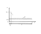
本方法のメリットを示すために、定常状態となった槽内の固形物濃度Cの概念的な経時変化を図3に示す。なお、以降では、排水時に全量排水する事例(前述のα=1)にて説明する。
本運転方法による装置(全量排水時を想定する)を点線1で示す。比較対照として連続的に排水を行う装置の例を実線2で、洗浄毎に極少量部分的に排水を行う装置の例を点破線3で示す。いずれも装置としての回収率Rは排水量を制御することにより同じに設定できる。槽内のCmaxもいずれも同じだが、膜ろ過工程の間、点線1が最も平均濃度が低いことがわかる。この平均濃度は該線と時間軸との間の面積に比例するから、上記は自明である。
Cmaxが、Ctより十分低い場合は、いずれの方法もケーキの成長の危険性はほとんどない。しかし実用的には回収率Rは高い方が好ましく、従ってCmaxはCt付近に設定することが多い。その場合、点線1の本運転方法は槽内固形物濃度がCt付近となる時間、即ち、Ctの遷移領域Cttとなる、あるいはCtt内に存在する時間Tctt1が最も短く、従ってケーキの成長の危険性が最も低いことがわかる。従来法2、3では、Ctt内に存在する時間Tctt2,3は、定常状態で常にCtt内にある。
一方、固形物含有水中の活性炭の槽内濃度を概念的に示したのが図4、活性炭の注入率を示したのが図5である。本方法による活性炭注入方法を点線1で、従来の一定注入方法を実線2で示す。
原水1に添加された活性炭は、ろ過及び洗浄を繰り返すにつれて槽内に蓄積する。排水工程直前には、槽内の活性炭の濃度は最大値amaxとなる。
次ぎに排水工程では、活性炭は排水とともに槽外に流出する。全量排水した場合、排水後は槽内の活性炭量は0となる。あるいは一部排水を行った場合でも、槽内の活性炭量は、排水前の1−α倍の量に低下する。(αは前述の、槽容量に対する排水量の割合)。従って、ろ過開始直後は槽内の活性炭量が十分でなく、従来技術にあるような一定注入では、有機物の除去効果が十分に期待できない。これらを是正するため、本方法では、活性炭注入率Aは、全量排水後の充水工程時(時間はt0で、Tより十分に短い)に一時的に高い注入率(A1)の活性炭を添加し、槽内の濃度をa0とする。その後ろ過時間Tの間は、時間と共に低下する槽内の活性炭吸着能を補う目的で、A1より少ない注入率(A2)で運転する。槽内の活性炭濃度は、運転経過に伴い漸増する。これを式で表すと以下の通りとなる。
a(t)=a0+A2Q(t−t0)/V
amax=a0+A2QT/V
a(t):運転t時間後の槽内活性炭濃度
a0:充水時間t0後の槽内活性炭濃度
Q:槽への時間当たりの流入量(膜供給水量)
V:槽容量
t:経過時間
t0:初期充水時間
T:ろ過時間
Hereinafter, an example of a preferred embodiment of the present invention will be described with reference to the drawings.
An example of the device of the present invention is shown in FIGS.
As shown in detail in FIG. 2, the membrane filtration device F includes a
The
When the solid-containing water concentration in the tank reaches Cmax, a part or all of the solid-containing water is drained 16 from the
After draining the entire amount, the
The maximum concentration Cmax of the solid concentration in the tank is approximated by Cmax = Co / (1-R) where R is the recovery rate of Co and treated water.
In addition, the filtration time T (h) until the total drainage is defined as V (m 3 ) for the tank volume and α as the ratio of the drainage capacity to the tank volume (α = 1 for total drainage). Assuming that (film supply water amount) is Q (m 3 / h), the relationship of R = Q · T / (Q · T + αV) is established. From this, T = αR · V / (Q · (1-R)), and by draining the entire amount of water in the tank every filtration time T, a high recovery rate is maintained within a range where the cake does not adhere to the membrane surface. be able to.
In order to show the merit of this method, the conceptual time-dependent change of the solid substance concentration C in the tank which became the steady state is shown in FIG. In the following, a case where all the water is drained during drainage (the above-described α = 1) will be described.
A dotted
If Cmax is well below Ct, there is little risk of cake growth for either method. However, in practice, it is preferable that the recovery rate R is high, and therefore Cmax is often set in the vicinity of Ct. In this case, the operation method indicated by the dotted
On the other hand, FIG. 4 conceptually shows the concentration of the activated carbon in the solid-containing water and FIG. 5 shows the injection rate of the activated carbon. The activated carbon injection method according to this method is indicated by a dotted
The activated carbon added to the
Next, in the drainage process, the activated carbon flows out of the tank together with the drainage. When the entire amount is drained, the amount of activated carbon in the tank becomes zero after draining. Or even when it drains partially, the amount of activated carbon in a tank falls to the quantity of 1-alpha times before drainage. (Α is the ratio of the amount of drainage to the tank capacity described above). Therefore, immediately after the start of filtration, the amount of activated carbon in the tank is not sufficient, and with the constant injection as in the prior art, the organic substance removal effect cannot be expected sufficiently. In order to correct these, in this method, the activated carbon injection rate A is activated carbon with a temporarily high injection rate (A 1 ) during the charging process after drainage of the entire amount (time is t 0 and is sufficiently shorter than T). It was added, the concentration in the bath with a 0. Thereafter, during the filtration time T, operation is performed at an injection rate (A 2 ) smaller than A 1 in order to compensate for the activated carbon adsorption capacity in the tank that decreases with time. The activated carbon concentration in the tank gradually increases as the operation progresses. This is expressed as follows.
a (t) = a 0 + A 2 Q (t−t 0 ) / V
a max = a 0 + A 2 QT / V
a (t): Activated carbon concentration in the tank after operation t time a 0 : Activated carbon concentration in the tank after the filling time t 0 Q: Inflow amount to the tank per hour (membrane supply water amount)
V: tank capacity t: elapsed time t 0 : initial water filling time T: filtration time
このような運転を行うことにより、ろ過初期からろ過時間Tを通じて安定した活性炭による処理が可能となる。
なお、活性炭の注入率について、水道施設設計指針2000(日本水道協会発行、p291)によれば、異臭味除去の場合10〜30mg/L、トリハロメタン前駆物質除去の場合30〜100mg/Lとされるが、実際には経済性の観点から5〜25mg/L程度の範囲で運用されることが多い。一方、活性炭の吸着性能の効果が持続する平均時間を5〜10時間とした場合、浸漬槽内の一般的滞留時間を30分とすると、浸漬槽内では実際の注入率の、10〜20倍の活性炭が蓄積する計算になる。これよりA1値はA2値の10〜20倍、すなわち50〜500mg/Lと高濃度とすることで、ろ過初期の有機物質除去能力を発現することができる。またろ過時間(排水と排水の間隔)は、膜ろ過流束、回収率によるが、通常、1日〜10日間程度の間となる。一方、充水時間t0は10分〜60分程度である。
By performing such an operation, stable activated carbon treatment can be performed from the beginning of filtration through the filtration time T.
In addition, about the injection | pouring rate of activated carbon, according to water supply facility design guideline 2000 (published by Japan Water Works Association, p291), it is set as 10-30 mg / L in the case of removing off-flavor, and 30-100 mg / L in the case of removing trihalomethane precursor. However, in practice, it is often operated in the range of about 5 to 25 mg / L from the viewpoint of economy. On the other hand, when the average time during which the effect of the adsorption performance of the activated carbon is maintained is 5 to 10 hours, when the general residence time in the immersion tank is 30 minutes, the actual injection rate in the immersion tank is 10 to 20 times. It becomes calculation that activated carbon accumulates. From this, the A 1 value is 10 to 20 times the A 2 value, that is, a high concentration of 50 to 500 mg / L, whereby the organic substance removing ability at the initial stage of filtration can be expressed. The filtration time (interval between drainage and drainage) depends on the membrane filtration flux and the recovery rate, but is usually between about 1 day and 10 days. On the other hand, is filled with water time t 0 is about 10 minutes to 60 minutes.
以下、本発明の実施例を説明する。なお、本発明はこの実施例により何等制限されるものではない。 Examples of the present invention will be described below. In addition, this invention is not restrict | limited at all by this Example.
本発明の成果を示す一例を表1に示す。図1〜5の装置構成並びに方法に準じて、実験1,2(比較例)は、20分間の洗浄毎に従来法による少量排水(1.2〜1.5L)した実験例であり、実験3(実施例)では、同20分間の洗浄毎には排水せず、約8日に1回全量を排水した。いずれも前記回収率Rは99.7%であるが、全量排水する方が槽内平均濁度は低い。また、ケーキの付着は、実験中、実験1、2では見られたのに対し、実験3ではケーキの膜面への付着は、実験中、いずれの工程でも見られなかった。
また紫外線吸光度を指標とする処理水水質は、1〜3いずれにおいても大きな違いはなく良好に処理された。
An example showing the results of the present invention is shown in Table 1. In accordance with the apparatus configuration and method of FIGS. 1 to 5,
Further, the quality of the treated water with the ultraviolet absorbance as an index was treated well without any significant difference in any of 1-3.

なお、実験の運転条件は以下の通りである。
原水:河川表流水
膜ろ過流速:0.8〜1.0m/d
膜供給水量Q:0.02〜0.025m3/L
膜浸漬槽容積V:0.7m3
活性炭添加量A:0〜25mg/L
回収率R:99.7%
原水紫外線吸光度:平均0.362
Cmaxは膜供給水固形物濃度Coと回収率Rから換算した数値
試験期間はいずれも30日以上
原水及び処理水の紫外線吸光度は、上水試験法(2001、社団法人日本水道協会)に従い波長260nmの吸光度を50mmのセルにより測定した。
The operating conditions of the experiment are as follows.
Raw water: River surface water Membrane filtration flow rate: 0.8-1.0 m / d
Membrane supply water amount Q: 0.02 to 0.025 m 3 / L
Membrane immersion tank volume V: 0.7 m 3
Activated carbon addition amount A: 0 to 25 mg / L
Recovery rate R: 99.7%
Raw water ultraviolet absorbance: average 0.362
Cmax is a numerical value converted from the membrane feed water solids concentration Co and the recovery rate R. Both test periods are 30 days or more. The ultraviolet absorbance of raw water and treated water is 260 nm according to the water test method (2001, Japan Water Works Association). Was measured with a 50 mm cell.
以上より、実験3に示される本特許法を用いた運転は、膜へのケーキ付着を抑制しつつ、良好な処理水水質を得る上で有効であることがわかった。
As mentioned above, it turned out that the operation | movement using this patent method shown in
1:原水、2:混和槽、3:攪拌機、F:膜ろ過装置、4:槽、5:膜モジュール、5a:膜エレメント、5b:集水部、5c:下部支持体、6:散気装置、7:ブロワ、8:排泥弁、9:吸引ポンプ、10:処理水槽、11:pH調整剤、12:凝集剤、13:粉末活性炭、14:流入弁、15:固形物含有水(膜供給水)、16:排水、17:ろ過水、18:洗浄空気、L0:通常水位、L1:排水後の水位 1: Raw water, 2: Mixing tank, 3: Stirrer, F: Membrane filtration device, 4: Tank, 5: Membrane module, 5a: Membrane element, 5b: Water collecting part, 5c: Lower support, 6: Air diffuser , 7: blower, 8: drainage valve, 9: suction pump, 10: treated water tank, 11: pH adjuster, 12: flocculant, 13: powdered activated carbon, 14: inflow valve, 15: solid-containing water (membrane) Supply water), 16: drainage, 17: filtered water, 18: washing air, L 0 : normal water level, L 1 : water level after drainage
Claims (7)
前記膜ろ過工程の間、任意に設定可能な時間間隔を設けて断続的に洗浄を行う洗浄工程と、
前記膜ろ過工程後に該槽内の固形物含有水を排水する排水工程と、
前記排水工程後に該槽内に原水を供給するとともに固形物含有水中の粉末活性炭濃度が50mg/L以上の目標値となるように制御する充水工程と
を含むことを特徴とする浄水処理方法。
{但し、上記固形物濃度とは、粉末活性炭、原水中の浮遊物質成分及び該浮遊物質成分の凝集剤による凝集フロックの総量の濃度をいう。} Solids concentration of solids-containing water in the tank is, until the cake adhering to the membrane surface is 3000~30000mg / L was determined in advance as a solid concentration at which begin to grow and have membrane filtration The solids-containing water Membrane filtration process ,
During the membrane filtration step, a cleaning step that performs cleaning intermittently with an arbitrarily settable time interval, and
A drain step of draining the solids-containing water in the cistern after the membrane filtration step,
Characterized in that it comprises a <br/> and filled with water steps powdered activated carbon concentration of solids content in water is controlled to a target value of more than 50 mg / L supplies raw water into the cistern after the drainage step Water purification method.
{However, the said solid substance concentration means the density | concentration of the total amount of the aggregation floc by the powdered activated carbon, the floating substance component in raw | natural water, and the flocculant of this floating substance component. }
前記凝集後に粉末活性炭を注入し固形物含有水を得る活性炭注入装置と、
前記固形物含有水が流入される槽、膜エレメント及び集水部を有し該槽内に浸漬される膜モジュール、並びに該槽下部に設置され該固形物含有水の排水時に洗浄空気を膜エレメントに供給する散気装置からなり、前記槽内の固形物含有水の固形物濃度が、膜面に付着するケーキが成長し始める時の固形物濃度として予め決定した3000〜30000mg/Lとなった時、該固形物含有水を排水する膜ろ過装置と、
を有することを特徴とする浄水処理装置。
{但し、上記固形物濃度とは、粉末活性炭、原水中の浮遊物質成分及び該浮遊物質成分の凝集剤による凝集フロックの総量の濃度をいう。} A mixing tank in which a flocculant is added to raw water and agglomerates by stirring;
An activated carbon injection device for injecting powdered activated carbon after the agglomeration to obtain solid-containing water;
A tank into which the solid-containing water is introduced, a membrane element and a membrane module having a water collecting part, and a membrane element that is installed in the lower part of the tank and is used to discharge cleaning air when draining the solid-containing water It consists diffuser you supplied to the solids concentration of the solids-containing water in the tank is a 3000~30000mg / L was determined in advance as a solid concentration when the cake adhering to the film surface starts to grow A membrane filtration device for draining the solid-containing water ,
The water purification apparatus characterized by having .
{However, the said solid substance concentration means the density | concentration of the total amount of the aggregation floc by the powdered activated carbon, the floating substance component in raw | natural water, and the flocculant of this floating substance component. }
運転t時間後の槽内活性炭濃度:a(t)=aActivated carbon concentration in the tank after operation t: a (t) = a 00 +A+ A 22 Q(t−tQ (t-t 00 )/V) / V
排水前の槽内活性炭濃度最大値:aMaximum activated carbon concentration in the tank before draining: a max max =a= A 00 +A+ A 22 QT/VQT / V
{但し、a{However, a 00 :充水時間t: Recharge time t 00 後の槽内活性炭濃度(槽内の濃度)、Q:槽への時間当たりの流入量(膜供給水量)、V:槽容量、t:経過時間、tThe concentration of activated carbon in the tank (concentration in the tank), Q: inflow amount to the tank per hour (film supply water amount), V: tank capacity, t: elapsed time, t 00 :初期充水時間、T:ろ過時間を示す。}: Initial charging time, T: Filtration time. }
{但し、Co:膜供給水の固形物濃度、R:処理水の回収率、V:槽の容積(m 3 )、α:排水容量の槽容積に対する割合、Q:時間当たりの流入量(m 3 /h)を示す}
であることを特徴とする請求項6記載の浄水処理装置。 The solid concentration (maximum concentration Cmax) of 3000 to 30000 mg / L determined in the tank is Cmax = Co / (1-R), and the filtration time T (h) to the total amount drainage is T = αR · V / (Q · (1-R))
{ However, Co: solid concentration of membrane feed water, R: recovery rate of treated water, V: volume of tank (m 3 ), α: ratio of drainage capacity to tank volume, Q: inflow per hour (m 3 / h)}
The water purification apparatus according to claim 6 .
Priority Applications (1)
| Application Number | Priority Date | Filing Date | Title |
|---|---|---|---|
| JP2011092918A JP5763400B2 (en) | 2011-04-19 | 2011-04-19 | Water purification method and water purification device |
Applications Claiming Priority (1)
| Application Number | Priority Date | Filing Date | Title |
|---|---|---|---|
| JP2011092918A JP5763400B2 (en) | 2011-04-19 | 2011-04-19 | Water purification method and water purification device |
Publications (3)
| Publication Number | Publication Date |
|---|---|
| JP2012223697A JP2012223697A (en) | 2012-11-15 |
| JP2012223697A5 JP2012223697A5 (en) | 2014-05-29 |
| JP5763400B2 true JP5763400B2 (en) | 2015-08-12 |
Family
ID=47274497
Family Applications (1)
| Application Number | Title | Priority Date | Filing Date |
|---|---|---|---|
| JP2011092918A Active JP5763400B2 (en) | 2011-04-19 | 2011-04-19 | Water purification method and water purification device |
Country Status (1)
| Country | Link |
|---|---|
| JP (1) | JP5763400B2 (en) |
Cited By (1)
| Publication number | Priority date | Publication date | Assignee | Title |
|---|---|---|---|---|
| JP2019055362A (en) * | 2017-09-21 | 2019-04-11 | オルガノ株式会社 | Membrane filtration device and membrane filtration method |
Families Citing this family (2)
| Publication number | Priority date | Publication date | Assignee | Title |
|---|---|---|---|---|
| CN103432783A (en) * | 2013-08-20 | 2013-12-11 | 翟志国 | Filter element for water purification |
| JP6616593B2 (en) * | 2015-06-10 | 2019-12-04 | オルガノ株式会社 | Membrane cleaning method |
Family Cites Families (2)
| Publication number | Priority date | Publication date | Assignee | Title |
|---|---|---|---|---|
| JP2001190937A (en) * | 2000-01-06 | 2001-07-17 | Sumitomo Heavy Ind Ltd | Water purification equipment and method of cleaning membrane element |
| JP5049929B2 (en) * | 2007-09-27 | 2012-10-17 | 株式会社神鋼環境ソリューション | Water treatment apparatus and water treatment method |
-
2011
- 2011-04-19 JP JP2011092918A patent/JP5763400B2/en active Active
Cited By (2)
| Publication number | Priority date | Publication date | Assignee | Title |
|---|---|---|---|---|
| JP2019055362A (en) * | 2017-09-21 | 2019-04-11 | オルガノ株式会社 | Membrane filtration device and membrane filtration method |
| JP7144925B2 (en) | 2017-09-21 | 2022-09-30 | オルガノ株式会社 | MEMBRANE FILTRATION DEVICE AND MEMBRANE FILTRATION METHOD |
Also Published As
| Publication number | Publication date |
|---|---|
| JP2012223697A (en) | 2012-11-15 |
Similar Documents
| Publication | Publication Date | Title |
|---|---|---|
| US10160678B2 (en) | Process for operating an upflow continuous backwash filter | |
| EP2694182B1 (en) | Method and system for filtration and filtration cake layer formation | |
| CN101475247B (en) | Short process flow water treatment technology with hyperfiltration as core and integrated with multiple water purifying technologies | |
| JP6027163B2 (en) | Water purification equipment | |
| JP5763400B2 (en) | Water purification method and water purification device | |
| JP5614644B2 (en) | Membrane filtration method | |
| JP2007289847A (en) | Raw tap water purification method and its apparatus | |
| CN103601312A (en) | Stone material sewage treatment system and method thereof | |
| JP7021461B2 (en) | Water treatment method, water treatment equipment and control method of addition of cake layer forming substance to raw water | |
| JP3891739B2 (en) | Operation method of membrane filtration device | |
| CN209411838U (en) | A kind of equipment of low energy consumption sewage treatment | |
| JP3149465B2 (en) | Automatic backwash control method for biological activated carbon treatment tower | |
| JP2003033764A (en) | Method and apparatus for washing filtration body by using ozone | |
| JP2007111576A (en) | Back-washing method of membrane module | |
| JP2003299911A (en) | Filter medium cleaning system and water treatment system | |
| JPH10286567A (en) | Membrane separating process | |
| JP3761154B2 (en) | Activated sludge solid-liquid separator | |
| JP4800462B2 (en) | Filtration method | |
| JP4124957B2 (en) | Filter body washing method and apparatus | |
| CN220098598U (en) | Mechanism for treating and recycling backwash wastewater of siphon filter tank | |
| JP3889254B2 (en) | Solid-liquid separation method and apparatus for biological treatment liquid of organic wastewater | |
| JP2006055852A (en) | Cleaning method and equipment for filter element | |
| WO2018074328A1 (en) | Water treatment apparatus and water treatment method | |
| JP2001353408A (en) | Flocculating and settling device | |
| JP4813143B2 (en) | Solid-liquid separation method and apparatus for activated sludge |
Legal Events
| Date | Code | Title | Description |
|---|---|---|---|
| RD04 | Notification of resignation of power of attorney |
Free format text: JAPANESE INTERMEDIATE CODE: A7424 Effective date: 20140210 |
|
| A521 | Request for written amendment filed |
Free format text: JAPANESE INTERMEDIATE CODE: A523 Effective date: 20140416 |
|
| A621 | Written request for application examination |
Free format text: JAPANESE INTERMEDIATE CODE: A621 Effective date: 20140416 |
|
| A977 | Report on retrieval |
Free format text: JAPANESE INTERMEDIATE CODE: A971007 Effective date: 20150123 |
|
| RD02 | Notification of acceptance of power of attorney |
Free format text: JAPANESE INTERMEDIATE CODE: A7422 Effective date: 20150202 |
|
| A131 | Notification of reasons for refusal |
Free format text: JAPANESE INTERMEDIATE CODE: A131 Effective date: 20150203 |
|
| A521 | Request for written amendment filed |
Free format text: JAPANESE INTERMEDIATE CODE: A523 Effective date: 20150403 |
|
| TRDD | Decision of grant or rejection written | ||
| A01 | Written decision to grant a patent or to grant a registration (utility model) |
Free format text: JAPANESE INTERMEDIATE CODE: A01 Effective date: 20150602 |
|
| A61 | First payment of annual fees (during grant procedure) |
Free format text: JAPANESE INTERMEDIATE CODE: A61 Effective date: 20150611 |
|
| R150 | Certificate of patent or registration of utility model |
Ref document number: 5763400 Country of ref document: JP Free format text: JAPANESE INTERMEDIATE CODE: R150 |
|
| R250 | Receipt of annual fees |
Free format text: JAPANESE INTERMEDIATE CODE: R250 |
|
| R250 | Receipt of annual fees |
Free format text: JAPANESE INTERMEDIATE CODE: R250 |
|
| R250 | Receipt of annual fees |
Free format text: JAPANESE INTERMEDIATE CODE: R250 |
|
| R250 | Receipt of annual fees |
Free format text: JAPANESE INTERMEDIATE CODE: R250 |
|
| R250 | Receipt of annual fees |
Free format text: JAPANESE INTERMEDIATE CODE: R250 |
|
| R250 | Receipt of annual fees |
Free format text: JAPANESE INTERMEDIATE CODE: R250 |