EP2694138B1 - Safety syringe for needleless injector - Google Patents
Safety syringe for needleless injector Download PDFInfo
- Publication number
- EP2694138B1 EP2694138B1 EP12767293.9A EP12767293A EP2694138B1 EP 2694138 B1 EP2694138 B1 EP 2694138B1 EP 12767293 A EP12767293 A EP 12767293A EP 2694138 B1 EP2694138 B1 EP 2694138B1
- Authority
- EP
- European Patent Office
- Prior art keywords
- plunger
- discharge end
- chamber
- orifice
- syringe
- Prior art date
- Legal status (The legal status is an assumption and is not a legal conclusion. Google has not performed a legal analysis and makes no representation as to the accuracy of the status listed.)
- Active
Links
Images


Classifications
-
- A—HUMAN NECESSITIES
- A61—MEDICAL OR VETERINARY SCIENCE; HYGIENE
- A61J—CONTAINERS SPECIALLY ADAPTED FOR MEDICAL OR PHARMACEUTICAL PURPOSES; DEVICES OR METHODS SPECIALLY ADAPTED FOR BRINGING PHARMACEUTICAL PRODUCTS INTO PARTICULAR PHYSICAL OR ADMINISTERING FORMS; DEVICES FOR ADMINISTERING FOOD OR MEDICINES ORALLY; BABY COMFORTERS; DEVICES FOR RECEIVING SPITTLE
- A61J1/00—Containers specially adapted for medical or pharmaceutical purposes
- A61J1/05—Containers specially adapted for medical or pharmaceutical purposes for collecting, storing or administering blood, plasma or medical fluids ; Infusion or perfusion containers
- A61J1/06—Ampoules or carpules
-
- A—HUMAN NECESSITIES
- A61—MEDICAL OR VETERINARY SCIENCE; HYGIENE
- A61M—DEVICES FOR INTRODUCING MEDIA INTO, OR ONTO, THE BODY; DEVICES FOR TRANSDUCING BODY MEDIA OR FOR TAKING MEDIA FROM THE BODY; DEVICES FOR PRODUCING OR ENDING SLEEP OR STUPOR
- A61M5/00—Devices for bringing media into the body in a subcutaneous, intra-vascular or intramuscular way; Accessories therefor, e.g. filling or cleaning devices, arm-rests
- A61M5/50—Devices for bringing media into the body in a subcutaneous, intra-vascular or intramuscular way; Accessories therefor, e.g. filling or cleaning devices, arm-rests having means for preventing re-use, or for indicating if defective, used, tampered with or unsterile
- A61M5/5013—Means for blocking the piston or the fluid passageway to prevent illegal refilling of a syringe
- A61M5/504—Means for blocking the piston or the fluid passageway to prevent illegal refilling of a syringe for blocking the fluid passageway
-
- A—HUMAN NECESSITIES
- A61—MEDICAL OR VETERINARY SCIENCE; HYGIENE
- A61M—DEVICES FOR INTRODUCING MEDIA INTO, OR ONTO, THE BODY; DEVICES FOR TRANSDUCING BODY MEDIA OR FOR TAKING MEDIA FROM THE BODY; DEVICES FOR PRODUCING OR ENDING SLEEP OR STUPOR
- A61M5/00—Devices for bringing media into the body in a subcutaneous, intra-vascular or intramuscular way; Accessories therefor, e.g. filling or cleaning devices, arm-rests
- A61M5/178—Syringes
- A61M5/30—Syringes for injection by jet action, without needle, e.g. for use with replaceable ampoules or carpules
-
- A—HUMAN NECESSITIES
- A61—MEDICAL OR VETERINARY SCIENCE; HYGIENE
- A61M—DEVICES FOR INTRODUCING MEDIA INTO, OR ONTO, THE BODY; DEVICES FOR TRANSDUCING BODY MEDIA OR FOR TAKING MEDIA FROM THE BODY; DEVICES FOR PRODUCING OR ENDING SLEEP OR STUPOR
- A61M5/00—Devices for bringing media into the body in a subcutaneous, intra-vascular or intramuscular way; Accessories therefor, e.g. filling or cleaning devices, arm-rests
- A61M5/178—Syringes
- A61M5/24—Ampoule syringes, i.e. syringes with needle for use in combination with replaceable ampoules or carpules, e.g. automatic
- A61M2005/2485—Ampoule holder connected to rest of syringe
- A61M2005/2488—Ampoule holder connected to rest of syringe via rotation, e.g. threads or bayonet
-
- A—HUMAN NECESSITIES
- A61—MEDICAL OR VETERINARY SCIENCE; HYGIENE
- A61M—DEVICES FOR INTRODUCING MEDIA INTO, OR ONTO, THE BODY; DEVICES FOR TRANSDUCING BODY MEDIA OR FOR TAKING MEDIA FROM THE BODY; DEVICES FOR PRODUCING OR ENDING SLEEP OR STUPOR
- A61M5/00—Devices for bringing media into the body in a subcutaneous, intra-vascular or intramuscular way; Accessories therefor, e.g. filling or cleaning devices, arm-rests
- A61M5/50—Devices for bringing media into the body in a subcutaneous, intra-vascular or intramuscular way; Accessories therefor, e.g. filling or cleaning devices, arm-rests having means for preventing re-use, or for indicating if defective, used, tampered with or unsterile
- A61M5/5013—Means for blocking the piston or the fluid passageway to prevent illegal refilling of a syringe
- A61M5/504—Means for blocking the piston or the fluid passageway to prevent illegal refilling of a syringe for blocking the fluid passageway
- A61M2005/5046—Means for blocking the piston or the fluid passageway to prevent illegal refilling of a syringe for blocking the fluid passageway automatically, e.g. plug actuated by the piston head, one-way valve
-
- A—HUMAN NECESSITIES
- A61—MEDICAL OR VETERINARY SCIENCE; HYGIENE
- A61M—DEVICES FOR INTRODUCING MEDIA INTO, OR ONTO, THE BODY; DEVICES FOR TRANSDUCING BODY MEDIA OR FOR TAKING MEDIA FROM THE BODY; DEVICES FOR PRODUCING OR ENDING SLEEP OR STUPOR
- A61M5/00—Devices for bringing media into the body in a subcutaneous, intra-vascular or intramuscular way; Accessories therefor, e.g. filling or cleaning devices, arm-rests
- A61M5/50—Devices for bringing media into the body in a subcutaneous, intra-vascular or intramuscular way; Accessories therefor, e.g. filling or cleaning devices, arm-rests having means for preventing re-use, or for indicating if defective, used, tampered with or unsterile
- A61M5/5066—Means for preventing re-use by disconnection of piston and piston-rod
- A61M2005/5073—Means for preventing re-use by disconnection of piston and piston-rod by breaking or rupturing the connection parts
-
- A—HUMAN NECESSITIES
- A61—MEDICAL OR VETERINARY SCIENCE; HYGIENE
- A61M—DEVICES FOR INTRODUCING MEDIA INTO, OR ONTO, THE BODY; DEVICES FOR TRANSDUCING BODY MEDIA OR FOR TAKING MEDIA FROM THE BODY; DEVICES FOR PRODUCING OR ENDING SLEEP OR STUPOR
- A61M5/00—Devices for bringing media into the body in a subcutaneous, intra-vascular or intramuscular way; Accessories therefor, e.g. filling or cleaning devices, arm-rests
- A61M5/178—Syringes
- A61M5/24—Ampoule syringes, i.e. syringes with needle for use in combination with replaceable ampoules or carpules, e.g. automatic
Definitions
- This invention relates to a disposable syringe, and in particular to a disposable syringe for single use in a needleless injector.
- Patent application US 2010/076374 A1 discloses a nozzle assembly for a needle-free injection device.
- the plunger includes a first portion and a second portion removably joined by a frangible region.
- Patent US 5,643,211 discloses a nozzle assembly adapted for an injector, which includes a frangible injector.
- Patent US 5,875,976 discloses a locking mechanism for aiding in the prevention of accidental or unintentional disengagement of the nozzle assembly from a needleless injection device.
- the invention provides a disposable syringe for a needleless injector comprising a tubular body having an open end and a closed end, a chamber in said body for receiving a fluid; a plunger slidable through said open end into said chamber; an orifice in the closed end of the tubular body for discharging fluid from the body when the plunger is pushed towards the orifice; a separable conical tip on a discharge end of the plunger for plugging said orifice when the plunger is pushed into said chamber during an injection; and a retainer for separating the tip from the remainder of the plunger when the plunger is retracted following an injection, characterized in that the retainer includes a conical discharge end of the chamber behind and connected to the orifice; an annular projection in said discharge end of the chamber; a discharge end on said plunger having the same shape as the discharge end of the chamber for mating with said discharge end of the chamber; and an annular groove in said discharge end of said plunger for receiving the projection, said groove
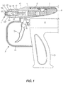
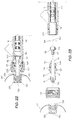
- a syringe in accordance with the present invention which is indicated generally at 1 is intended for use in a needleless injector 2, which in this case is in the shape of a pistol.
- the injector 2 includes a body with a handle 3 extending downwardly from approximately the center thereof.
- the body is defined by upper and lower cylinders 5 and 6, respectively, which contain most of the remaining elements of the injector.
- the elements of the injector 2 are the same as or similar to the elements of the injector described in above-mentioned US 7,357,915 .
- a brass piston 7 is slidably mounted in the cylinder 5.
- the piston 7 is generally cup-shaped, including a rear recess for receiving a cylindrical, permanent magnet 8.
- a tubular barrel 10 is connected to the front end of the cylinder 5.
- the piston 7 is used to drive a plunger 11 mounted on the front end of the piston 7. Movement of the piston 7 and the plunger 11 are controlled by a trigger 13, which is protected by a trigger guard 14, and a plunger 15 extending out of the cylinder 6 for controlling a valve (not shown) in the cylinder 6.
- the valve is similar to that disclosed by the above-referenced US 7,357,915 . Forward movement of the plunger 11 in the barrel 10 causes operation of the syringe 1.
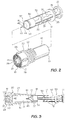
- the syringe 1 includes a tubular body 16 for slidably receiving a piston or plunger 17.
- the body 16 has an open inner end 18 (when mounted in the barrel 10 of the injector) and a closed outer end 19.
- An annular flange 20 near the outer end 19 limits movement of the body 16 into the barrel 10.
- Threads 22 on the body 16 behind the flange 20 engage the internally threaded discharge end 23 of the injector barrel 10 when mounting the syringe in the injector.
- Fluid, typically medicine, from a chamber 24 in the body 16 is discharged through an orifice 25 in the outer end 19 of the body 16.
- An externally threaded recess 27 in the end 19 forms part of a luer lock for connecting a conventional externally threaded needle, catheter or other device (not shown) to the syringe.
- Longitudinally extending ribs 28 on the cylindrical outer end 19 of the body 16 facilitate gripping of the body when screwing the syringe into the injector barrel 10.
- Radially extending teeth 29 on the annular periphery of the closed end 19 of the body 16 prevent rotation of the body when the injector is in use, i.e. when the orifice 25 or the outer end 19 of the body 16 is pressed against the skin during an injection.
- the plunger 17 includes an elongated, body 30 of cruciform cross section throughout most of its length with reinforcing gussets 31.
- a pair of spaced apart discs 32 and 33 are provided at and near the inner end of the body 30.
- the disc 32 is engaged by the plunger 11 during an injection.
- the disc 33 slides into the narrow discharge end of the barrel 10 during injection and limits movement of the plunger 17 into the body 16 of the syringe.
- a third disc-shaped reinforcing rib 35 is provided roughly halfway between the rib 33 and the cylindrical outer end 36 of the plunger body 30.
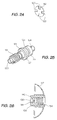
- a skirt 37 flares outwardly from an annular recess 38 ( Fig. 2 ) in the outer end of the body 30 for sealing engagement with the passage 24.
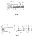
- the discharge end 40 of the chamber 24 and the corresponding end 41 of the plunger 17 have essentially the same shape, i.e. conical.
- the end 40 of the passage 24 tapers to the orifice 25 and includes an annular projection or restriction 42.
- the end 41 of the plunger 17 has a taper identical to that of the end 40 of the passage 24, and an annular groove 44 (line of weakness) near the tip 45 thereof.
- a longitudinally extending slot 46 is provided in the tip 45 so that the tip can compress when encountering the restriction 42.
- the orifice end of the syringe is connected to a medicine bottle (not shown) and the plunger 17 is retracted to draw medicine into the passage 24.
- the plunger 17 is pushed into the body 16 ( Fig. 6 )
- the tip 45 is jammed into the end 40 of the passage 24, and the projection 42 enters the groove 44.
- the plunger 17 is retracted ( Fig. 7 )
- the narrow tip 45 of the plunger remains in position against the orifice 25 while the remainder of the plunger is retracted.
- the orifice 25 is permanently blocked from the inside, prevent re-use of the syringe.
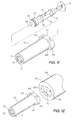
- a guard 50 can be mounted on the end 19 of the syringe body 16.
- the guard 50 performs a dual function, viz it prevents spray from the injection site, and spaces the orifice 25 from the injection site.
- the guard 50 is shaped like a cap with a circular outer end 51 and a cylindrical side wall 52.
- a central hole 54 in the end 51 permits passage of fluid from the orifice 25 to an injection site. Because the orifice 25 is spaced from the injection site by the thickness of the end 51, the force of the fluid is less than if the orifice 25 was pressed against the injection site.
- the guard 50 is used when making subcutaneous injections.
- An externally threaded sleeve 58 integral with the end 51 mates with the threaded recess 27 in the end 19 of the body 16 to connect the guard 50 to the syringe.
- Projections or ribs 59 are gripped when screwing the syringe into the barrel 10 of the injector.
- a thin, cup-shaped shield 60 extends outwardly from the rear end of the side wall 52 for surrounding an injection site.
- a second embodiment of the invention includes a tubular body 62 with a pair of arcuate ears 63 at the inner end 64 thereof.
- the ears 63 are used in a bayonet coupling for mounting the syringe in the end of an injector barrel 66, one end 67 of which is shown in Fig. 12 .
- the interior of the open end 67 of the barrel 66 includes a pair of opposed recesses 68 for receiving the ears 63.
- the ears 63 pass through the recesses 68, and then the body 62 is rotated to releasably lock the syringe in the barrel 66.
- the outer end 71 of the body 62 contains an orifice 72 and a threaded recess 73 for use in a luer connector.
- a plunger 74 is slidably mounted in the body 62.
- the plunger 74 includes an elongated body 75 of cruciform cross section reinforced by disc-shaped ribs 76.
- a large disc 78 on the inner end 79 of the body 75 supports the body for sliding in the injector barrel 66.
- a cylindrical head 80 on the outer end of the plunger body 75 contains a groove 81, carrying an O-ring 82 ( Figs. 13 to 15 ) for sealing the plunger 74 in the body 62 of the syringe.
- the outer discharge end 83 of a chamber 84 in the syringe body 62 is conical.
- a conical head 86 on the outer end 80 of the plunger is jammed into the conical end 83 of the chamber 84. Because the head 86 is connected to the remainder of the plunger body 75 by a very narrow, frangible neck 87, when the plunger 74 is retracted, the head 86 remains in the conical end 83 of the chamber 84.
- the orifice 72 is sealed, preventing re-use of the syringe.
- the diameters of the conical discharge end 83 of the chamber 84 and the head 86 must be such that the head is retained in the passage by friction; i.e. they must be the same size or the head can be slightly larger in diameter than the passage.
- the outer end 80 of the plunger 74 includes a cylindrical recess 90 holding the cylindrical inner end of a generally conical head 91.
- the head 91 contains an annular groove 92 ( Fig. 16 ) and the generally conical discharge end 94 of the chamber 95 contains an annular projection 96.
- the head 86 in the second embodiment of the invention Figs. 13 to 15
- the plunger 74 is extended ( Fig. 17 )
- the head 91 is jammed into the end 94 of the chamber 95.
- the projection 96 mates with the recess 92 in the head 91.
- the plunger 74 is retracted ( Fig. 18 )
- the head 91 remains in the discharge end 94 of the chamber 95 is blocking the orifice 72.
- the outer end 80 of the plunger 74 includes a narrow diameter, cylindrical projection 98 carrying a head 99, which is separable from the end 80.
- the head 99 includes a recess 100 in the inner end thereof.
- the conical tip 102 of the head 99 is jammed into the conical discharge end 103 of the medicine chamber 105 to seal the orifice 72.
- Figure 22 to 26 illustrate disposable nozzle assemblies in accordance with the invention.
- the nozzle assemblies of Figs. 22 to 26 are intended for use on a disposable injector of the type illustrated in US 7,357,915 .
- the discharge end 109 of the barrel 110 of the earlier injector includes a piston assembly 111 for forcing liquid through a valve 112 defined by a flexible, hollow valve stem 113 in the inlet end 114 of a nozzle 115, and a flexible rubber valve head 116.
- a circular stainless steel spacer 118 is sandwiched between the valve head 116 and an annular shoulder 119 in the barrel 110.
- the spacer 118 includes four diametrically opposed notches 120 or a plurality of such notches in the periphery thereof. The notches 120 permit the flow of liquid around the valve head 116.
- the nozzle 115 is defined by a tubular body 121 with a passage 122 therethrough.
- a pair of diametrically opposed holes 124 in the inner or inlet end of the body 121 are normally closed by the valve stem 113.
- the body 121 is slidable in the open discharge end of the barrel 110.
- An annular groove 125 ( Fig. 25 ) in the body 121 receives an O-ring 126 for sealing the nozzle in the barrel 110.
- An annular flange 127 on the middle of the body 121 is sandwiched between the outlet end of the barrel 110 and an internally threaded cap or nut 128 mounted on the externally threaded outer end 109 of the barrel 110. Liquid is discharged from the nozzle 115 through an orifice 130 in the otherwise closed outer end of the body 121.
- the outer end of the body 121 includes external threads 131 for mating with the internally threaded tubular body 134 of a guard 135. Liquid exiting the orifice 130 is discharged through an aligned orifice 136 in the body 134.
- a generally hemispherical shield 137 extends outwardly from the inner or rear end of the guard body 134.
- the guard 139 of Fig. 26 is similar to the guard 135 of Figs. 22 and 23 , except that the outer end 140 of the body 134 is thicker and includes a cylindrical recess 141. Thus, when the outer end 140 is pressed against an injection site (not shown), there is a gap between the orifice 136 and the injection site.
Applications Claiming Priority (2)
| Application Number | Priority Date | Filing Date | Title |
|---|---|---|---|
| US201161457460P | 2011-04-04 | 2011-04-04 | |
| PCT/CA2012/000332 WO2012135943A1 (en) | 2011-04-04 | 2012-04-03 | Safety syringe for needleless injector |
Publications (3)
| Publication Number | Publication Date |
|---|---|
| EP2694138A1 EP2694138A1 (en) | 2014-02-12 |
| EP2694138A4 EP2694138A4 (en) | 2014-11-12 |
| EP2694138B1 true EP2694138B1 (en) | 2016-05-18 |
Family
ID=46968499
Family Applications (1)
| Application Number | Title | Priority Date | Filing Date |
|---|---|---|---|
| EP12767293.9A Active EP2694138B1 (en) | 2011-04-04 | 2012-04-03 | Safety syringe for needleless injector |
Country Status (10)
| Country | Link |
|---|---|
| US (1) | US9662460B2 (es) |
| EP (1) | EP2694138B1 (es) |
| JP (1) | JP6138759B2 (es) |
| KR (1) | KR101945554B1 (es) |
| CN (1) | CN103582504B (es) |
| CA (1) | CA2847172C (es) |
| ES (1) | ES2600917T3 (es) |
| IL (1) | IL228753B (es) |
| RU (1) | RU2595504C2 (es) |
| WO (1) | WO2012135943A1 (es) |
Families Citing this family (18)
| Publication number | Priority date | Publication date | Assignee | Title |
|---|---|---|---|---|
| CN102921074A (zh) * | 2012-11-02 | 2013-02-13 | 江苏丞宇米特医疗科技有限公司 | 一种新型同种药液连续多次注射的无针注射器 |
| CN102921073A (zh) * | 2012-11-02 | 2013-02-13 | 江苏丞宇米特医疗科技有限公司 | 一种用于不同种药液的无针头快速注射器 |
| US9233208B2 (en) | 2012-11-29 | 2016-01-12 | Becton, Dickinson And Company | Methods and apparatus for disinfecting and reflux prevention flush syringe assembly |
| US10426700B2 (en) * | 2017-11-28 | 2019-10-01 | International Business Machines Corporation | Syringe accessory for transfer of air sensitive materials |
| US20200155771A1 (en) * | 2018-11-16 | 2020-05-21 | Plas-Tech Engineering, Inc. | Systems and Methods Related to Syringes |
| CN109432553B (zh) * | 2018-11-19 | 2024-04-16 | 北京快舒尔医疗技术有限公司 | 无针注射器的储药管的注射头组件、储药管和无针注射器 |
| KR20200082043A (ko) * | 2018-12-28 | 2020-07-08 | 주식회사 지티지웰니스 | 약물주입장치 |
| KR102088830B1 (ko) | 2019-12-05 | 2020-03-13 | 바즈바이오메딕(주) | 무바늘 주사기 |
| KR102093951B1 (ko) | 2019-12-05 | 2020-03-26 | 바즈바이오메딕(주) | 무바늘 주사기 |
| KR20220147651A (ko) * | 2020-02-27 | 2022-11-03 | 이데 인터내셔널 알앤디 인코퍼레이션 | 도스 조정 가능한 니들리스 인젝터 |
| KR102165136B1 (ko) | 2020-03-06 | 2020-10-13 | 바즈바이오메딕(주) | 무바늘 주사기 |
| KR102165137B1 (ko) | 2020-03-06 | 2020-10-13 | 바즈바이오메딕(주) | 무바늘 주사기 |
| KR102311646B1 (ko) | 2020-10-06 | 2021-10-12 | 바즈바이오메딕(주) | 노즐 교체형 무바늘 주사기 |
| KR102290090B1 (ko) * | 2021-01-18 | 2021-08-18 | 이수미 | 주입 건을 이용한 니들리스 주사액 주입장치 |
| KR102290085B1 (ko) * | 2021-01-18 | 2021-08-17 | 이수미 | 인체 피부에 주사액을 주입하기 위한 니들리스 주사액 주입방법 및 니들리스 주사액 주입장치 |
| KR102335681B1 (ko) | 2021-08-25 | 2021-12-06 | 바즈바이오메딕(주) | 무바늘 주사기 |
| KR102480640B1 (ko) | 2021-09-30 | 2022-12-23 | 바즈바이오메딕(주) | 약물 주입 성능의 조절이 가능한 무바늘 주사 시스템 |
| CN115591055B (zh) * | 2022-08-24 | 2023-11-07 | 江苏乐聚医药科技有限公司 | 差动型无针注射器 |
Family Cites Families (24)
| Publication number | Priority date | Publication date | Assignee | Title |
|---|---|---|---|---|
| US3301256A (en) * | 1964-03-30 | 1967-01-31 | Pharmaseal Lab | Hypodermic syringe having improved needle hub retaining sleeve means |
| JPH02147069A (ja) * | 1988-11-29 | 1990-06-06 | Terumo Corp | 使い拾て用シリンジ |
| US4950251A (en) * | 1989-03-13 | 1990-08-21 | Haining Michael L | Simplified retractable needle syringe |
| US5064413A (en) * | 1989-11-09 | 1991-11-12 | Bioject, Inc. | Needleless hypodermic injection device |
| RU2017505C1 (ru) * | 1991-02-25 | 1994-08-15 | Сергей Иванович Нестеренко | Шприц |
| US5149323A (en) * | 1991-04-08 | 1992-09-22 | Colonna John P | Self destruct double syringe |
| US5190523A (en) | 1991-08-16 | 1993-03-02 | Idee International R & D Inc. | Disposable syringe and injector |
| NO301523B1 (no) * | 1996-02-06 | 1997-11-10 | Pettersen Tor Erling | Selvdestruerende injeksjonsspröyte |
| JP2001505069A (ja) * | 1996-02-29 | 2001-04-17 | メディ―ジェクト コーポレイション | 調整可能なプランジャ移動ギャップを備えたノズル組立体 |
| US5643211A (en) * | 1996-02-29 | 1997-07-01 | Medi-Ject Corporation | Nozzle assembly having a frangible plunger |
| US5875976A (en) | 1996-12-24 | 1999-03-02 | Medi-Ject Corporation | Locking mechanism for nozzle assembly |
| WO1998048699A1 (en) | 1997-04-30 | 1998-11-05 | The Board Of Trustees Of The Leland Stanford Junior University | Method of imaging cell death in vivo |
| US6063054A (en) * | 1998-05-13 | 2000-05-16 | Mark L. Anderson | Injector pump |
| US6267749B1 (en) * | 1998-12-29 | 2001-07-31 | Safeguard Medical Limited | Single use syringe with breakaway plunger |
| AU2001253458C1 (en) * | 2001-04-13 | 2006-05-18 | Penjet Corporation | Modular gas-pressured needle-less injector |
| CA2371466C (en) * | 2002-02-12 | 2010-02-09 | Medical International Technology (Mit) Inc. | Needleless injector |
| US7056301B2 (en) * | 2003-09-05 | 2006-06-06 | Jung-O Liu | Syringe |
| US20080065027A1 (en) * | 2004-09-16 | 2008-03-13 | Sharp Fraser R | Disposable Safety Syringe to Prevent Needlestick Injuries and Reuse |
| US20070073225A1 (en) * | 2005-07-15 | 2007-03-29 | Shuei-Yuan Lee | Retractable safety syringe |
| WO2007140610A1 (en) * | 2006-06-07 | 2007-12-13 | Acushot Inc. | Charging mechanism for a needle-free injector |
| US7744563B2 (en) * | 2007-02-23 | 2010-06-29 | Bioject, Inc. | Needle-free injection devices and drug delivery systems therefor |
| US20090137949A1 (en) * | 2007-11-26 | 2009-05-28 | Bioject Inc. | Needle-free injection device with nozzle auto-disable |
| US8617099B2 (en) * | 2007-11-26 | 2013-12-31 | Bioject Inc. | Injection device plunger auto-disable |
| CA2729004C (en) * | 2008-06-26 | 2014-09-16 | Becton, Dickinson And Company | Passive reuse prevention syringe that uses a retaining ring lock |
-
2012
- 2012-04-03 RU RU2013148637/14A patent/RU2595504C2/ru active
- 2012-04-03 WO PCT/CA2012/000332 patent/WO2012135943A1/en active Application Filing
- 2012-04-03 KR KR1020137029133A patent/KR101945554B1/ko active IP Right Grant
- 2012-04-03 JP JP2014502962A patent/JP6138759B2/ja active Active
- 2012-04-03 CN CN201280027424.6A patent/CN103582504B/zh active Active
- 2012-04-03 US US13/261,754 patent/US9662460B2/en active Active
- 2012-04-03 CA CA2847172A patent/CA2847172C/en active Active
- 2012-04-03 EP EP12767293.9A patent/EP2694138B1/en active Active
- 2012-04-03 ES ES12767293.9T patent/ES2600917T3/es active Active
-
2013
- 2013-10-06 IL IL228753A patent/IL228753B/en active IP Right Grant
Also Published As
| Publication number | Publication date |
|---|---|
| CA2847172C (en) | 2019-07-09 |
| US9662460B2 (en) | 2017-05-30 |
| WO2012135943A1 (en) | 2012-10-11 |
| EP2694138A4 (en) | 2014-11-12 |
| RU2013148637A (ru) | 2015-05-10 |
| US20140018731A1 (en) | 2014-01-16 |
| JP2014514062A (ja) | 2014-06-19 |
| ES2600917T3 (es) | 2017-02-13 |
| JP6138759B2 (ja) | 2017-05-31 |
| EP2694138A1 (en) | 2014-02-12 |
| KR20140040125A (ko) | 2014-04-02 |
| KR101945554B1 (ko) | 2019-02-07 |
| RU2595504C2 (ru) | 2016-08-27 |
| CN103582504B (zh) | 2016-04-27 |
| IL228753B (en) | 2018-04-30 |
| IL228753A0 (en) | 2013-12-31 |
| CA2847172A1 (en) | 2012-10-11 |
| CN103582504A (zh) | 2014-02-12 |
Similar Documents
| Publication | Publication Date | Title |
|---|---|---|
| EP2694138B1 (en) | Safety syringe for needleless injector | |
| TWI510263B (zh) | 無針注射器 | |
| EP2424601B1 (en) | Passive refuse prevention syringe that uses a tip lock | |
| EP2903663B1 (en) | Injector apparatus | |
| US20140316336A1 (en) | Auto-disable safety syringe | |
| US20120226241A1 (en) | Safety syringe with retractable rotation | |
| KR20140005178U (ko) | 일회용 안전주사기 | |
| US20090131879A1 (en) | Safety disposable syringe | |
| EP2435115B1 (en) | Needleless injector accessories | |
| EP3508238B1 (en) | Support structure | |
| EP3104911B1 (en) | Syringe | |
| WO2004096326A1 (en) | Syringe system | |
| EP2153856B1 (en) | Auto disable device for syringes | |
| US9802032B2 (en) | Connecting module and syringe having such a connecting module |
Legal Events
| Date | Code | Title | Description |
|---|---|---|---|
| PUAI | Public reference made under article 153(3) epc to a published international application that has entered the european phase |
Free format text: ORIGINAL CODE: 0009012 |
|
| 17P | Request for examination filed |
Effective date: 20131031 |
|
| AK | Designated contracting states |
Kind code of ref document: A1 Designated state(s): AL AT BE BG CH CY CZ DE DK EE ES FI FR GB GR HR HU IE IS IT LI LT LU LV MC MK MT NL NO PL PT RO RS SE SI SK SM TR |
|
| DAX | Request for extension of the european patent (deleted) | ||
| REG | Reference to a national code |
Ref country code: DE Ref legal event code: R079 Ref document number: 602012018669 Country of ref document: DE Free format text: PREVIOUS MAIN CLASS: A61M0005300000 Ipc: A61M0005240000 |
|
| A4 | Supplementary search report drawn up and despatched |
Effective date: 20141013 |
|
| RIC1 | Information provided on ipc code assigned before grant |
Ipc: A61M 5/24 20060101AFI20141007BHEP Ipc: A61M 5/50 20060101ALI20141007BHEP Ipc: A61M 5/30 20060101ALI20141007BHEP Ipc: A61J 1/06 20060101ALI20141007BHEP |
|
| GRAP | Despatch of communication of intention to grant a patent |
Free format text: ORIGINAL CODE: EPIDOSNIGR1 |
|
| INTG | Intention to grant announced |
Effective date: 20151110 |
|
| GRAS | Grant fee paid |
Free format text: ORIGINAL CODE: EPIDOSNIGR3 |
|
| GRAA | (expected) grant |
Free format text: ORIGINAL CODE: 0009210 |
|
| AK | Designated contracting states |
Kind code of ref document: B1 Designated state(s): AL AT BE BG CH CY CZ DE DK EE ES FI FR GB GR HR HU IE IS IT LI LT LU LV MC MK MT NL NO PL PT RO RS SE SI SK SM TR |
|
| REG | Reference to a national code |
Ref country code: GB Ref legal event code: FG4D |
|
| REG | Reference to a national code |
Ref country code: CH Ref legal event code: EP |
|
| REG | Reference to a national code |
Ref country code: IE Ref legal event code: FG4D Ref country code: AT Ref legal event code: REF Ref document number: 799868 Country of ref document: AT Kind code of ref document: T Effective date: 20160615 |
|
| REG | Reference to a national code |
Ref country code: DE Ref legal event code: R096 Ref document number: 602012018669 Country of ref document: DE |
|
| REG | Reference to a national code |
Ref country code: NL Ref legal event code: FP |
|
| REG | Reference to a national code |
Ref country code: LT Ref legal event code: MG4D |
|
| PG25 | Lapsed in a contracting state [announced via postgrant information from national office to epo] |
Ref country code: NO Free format text: LAPSE BECAUSE OF FAILURE TO SUBMIT A TRANSLATION OF THE DESCRIPTION OR TO PAY THE FEE WITHIN THE PRESCRIBED TIME-LIMIT Effective date: 20160818 Ref country code: FI Free format text: LAPSE BECAUSE OF FAILURE TO SUBMIT A TRANSLATION OF THE DESCRIPTION OR TO PAY THE FEE WITHIN THE PRESCRIBED TIME-LIMIT Effective date: 20160518 Ref country code: LT Free format text: LAPSE BECAUSE OF FAILURE TO SUBMIT A TRANSLATION OF THE DESCRIPTION OR TO PAY THE FEE WITHIN THE PRESCRIBED TIME-LIMIT Effective date: 20160518 |
|
| REG | Reference to a national code |
Ref country code: AT Ref legal event code: MK05 Ref document number: 799868 Country of ref document: AT Kind code of ref document: T Effective date: 20160518 |
|
| PG25 | Lapsed in a contracting state [announced via postgrant information from national office to epo] |
Ref country code: LV Free format text: LAPSE BECAUSE OF FAILURE TO SUBMIT A TRANSLATION OF THE DESCRIPTION OR TO PAY THE FEE WITHIN THE PRESCRIBED TIME-LIMIT Effective date: 20160518 Ref country code: RS Free format text: LAPSE BECAUSE OF FAILURE TO SUBMIT A TRANSLATION OF THE DESCRIPTION OR TO PAY THE FEE WITHIN THE PRESCRIBED TIME-LIMIT Effective date: 20160518 Ref country code: SE Free format text: LAPSE BECAUSE OF FAILURE TO SUBMIT A TRANSLATION OF THE DESCRIPTION OR TO PAY THE FEE WITHIN THE PRESCRIBED TIME-LIMIT Effective date: 20160518 Ref country code: GR Free format text: LAPSE BECAUSE OF FAILURE TO SUBMIT A TRANSLATION OF THE DESCRIPTION OR TO PAY THE FEE WITHIN THE PRESCRIBED TIME-LIMIT Effective date: 20160819 Ref country code: HR Free format text: LAPSE BECAUSE OF FAILURE TO SUBMIT A TRANSLATION OF THE DESCRIPTION OR TO PAY THE FEE WITHIN THE PRESCRIBED TIME-LIMIT Effective date: 20160518 Ref country code: PT Free format text: LAPSE BECAUSE OF FAILURE TO SUBMIT A TRANSLATION OF THE DESCRIPTION OR TO PAY THE FEE WITHIN THE PRESCRIBED TIME-LIMIT Effective date: 20160919 |
|
| PG25 | Lapsed in a contracting state [announced via postgrant information from national office to epo] |
Ref country code: CZ Free format text: LAPSE BECAUSE OF FAILURE TO SUBMIT A TRANSLATION OF THE DESCRIPTION OR TO PAY THE FEE WITHIN THE PRESCRIBED TIME-LIMIT Effective date: 20160518 Ref country code: EE Free format text: LAPSE BECAUSE OF FAILURE TO SUBMIT A TRANSLATION OF THE DESCRIPTION OR TO PAY THE FEE WITHIN THE PRESCRIBED TIME-LIMIT Effective date: 20160518 Ref country code: RO Free format text: LAPSE BECAUSE OF FAILURE TO SUBMIT A TRANSLATION OF THE DESCRIPTION OR TO PAY THE FEE WITHIN THE PRESCRIBED TIME-LIMIT Effective date: 20160518 Ref country code: DK Free format text: LAPSE BECAUSE OF FAILURE TO SUBMIT A TRANSLATION OF THE DESCRIPTION OR TO PAY THE FEE WITHIN THE PRESCRIBED TIME-LIMIT Effective date: 20160518 Ref country code: SK Free format text: LAPSE BECAUSE OF FAILURE TO SUBMIT A TRANSLATION OF THE DESCRIPTION OR TO PAY THE FEE WITHIN THE PRESCRIBED TIME-LIMIT Effective date: 20160518 |
|
| REG | Reference to a national code |
Ref country code: ES Ref legal event code: FG2A Ref document number: 2600917 Country of ref document: ES Kind code of ref document: T3 Effective date: 20170213 |
|
| REG | Reference to a national code |
Ref country code: DE Ref legal event code: R097 Ref document number: 602012018669 Country of ref document: DE |
|
| PG25 | Lapsed in a contracting state [announced via postgrant information from national office to epo] |
Ref country code: BE Free format text: LAPSE BECAUSE OF FAILURE TO SUBMIT A TRANSLATION OF THE DESCRIPTION OR TO PAY THE FEE WITHIN THE PRESCRIBED TIME-LIMIT Effective date: 20160518 Ref country code: PL Free format text: LAPSE BECAUSE OF FAILURE TO SUBMIT A TRANSLATION OF THE DESCRIPTION OR TO PAY THE FEE WITHIN THE PRESCRIBED TIME-LIMIT Effective date: 20160518 Ref country code: AT Free format text: LAPSE BECAUSE OF FAILURE TO SUBMIT A TRANSLATION OF THE DESCRIPTION OR TO PAY THE FEE WITHIN THE PRESCRIBED TIME-LIMIT Effective date: 20160518 Ref country code: SM Free format text: LAPSE BECAUSE OF FAILURE TO SUBMIT A TRANSLATION OF THE DESCRIPTION OR TO PAY THE FEE WITHIN THE PRESCRIBED TIME-LIMIT Effective date: 20160518 |
|
| PLBE | No opposition filed within time limit |
Free format text: ORIGINAL CODE: 0009261 |
|
| STAA | Information on the status of an ep patent application or granted ep patent |
Free format text: STATUS: NO OPPOSITION FILED WITHIN TIME LIMIT |
|
| REG | Reference to a national code |
Ref country code: FR Ref legal event code: PLFP Year of fee payment: 6 |
|
| 26N | No opposition filed |
Effective date: 20170221 |
|
| PG25 | Lapsed in a contracting state [announced via postgrant information from national office to epo] |
Ref country code: SI Free format text: LAPSE BECAUSE OF FAILURE TO SUBMIT A TRANSLATION OF THE DESCRIPTION OR TO PAY THE FEE WITHIN THE PRESCRIBED TIME-LIMIT Effective date: 20160518 |
|
| PG25 | Lapsed in a contracting state [announced via postgrant information from national office to epo] |
Ref country code: MC Free format text: LAPSE BECAUSE OF FAILURE TO SUBMIT A TRANSLATION OF THE DESCRIPTION OR TO PAY THE FEE WITHIN THE PRESCRIBED TIME-LIMIT Effective date: 20160518 |
|
| REG | Reference to a national code |
Ref country code: IE Ref legal event code: MM4A |
|
| PG25 | Lapsed in a contracting state [announced via postgrant information from national office to epo] |
Ref country code: LU Free format text: LAPSE BECAUSE OF NON-PAYMENT OF DUE FEES Effective date: 20170403 |
|
| REG | Reference to a national code |
Ref country code: FR Ref legal event code: PLFP Year of fee payment: 7 |
|
| PG25 | Lapsed in a contracting state [announced via postgrant information from national office to epo] |
Ref country code: IE Free format text: LAPSE BECAUSE OF NON-PAYMENT OF DUE FEES Effective date: 20170403 |
|
| PG25 | Lapsed in a contracting state [announced via postgrant information from national office to epo] |
Ref country code: MT Free format text: LAPSE BECAUSE OF NON-PAYMENT OF DUE FEES Effective date: 20170403 |
|
| PG25 | Lapsed in a contracting state [announced via postgrant information from national office to epo] |
Ref country code: AL Free format text: LAPSE BECAUSE OF FAILURE TO SUBMIT A TRANSLATION OF THE DESCRIPTION OR TO PAY THE FEE WITHIN THE PRESCRIBED TIME-LIMIT Effective date: 20160518 |
|
| PG25 | Lapsed in a contracting state [announced via postgrant information from national office to epo] |
Ref country code: HU Free format text: LAPSE BECAUSE OF FAILURE TO SUBMIT A TRANSLATION OF THE DESCRIPTION OR TO PAY THE FEE WITHIN THE PRESCRIBED TIME-LIMIT; INVALID AB INITIO Effective date: 20120403 |
|
| PG25 | Lapsed in a contracting state [announced via postgrant information from national office to epo] |
Ref country code: BG Free format text: LAPSE BECAUSE OF FAILURE TO SUBMIT A TRANSLATION OF THE DESCRIPTION OR TO PAY THE FEE WITHIN THE PRESCRIBED TIME-LIMIT Effective date: 20160518 |
|
| PG25 | Lapsed in a contracting state [announced via postgrant information from national office to epo] |
Ref country code: CY Free format text: LAPSE BECAUSE OF NON-PAYMENT OF DUE FEES Effective date: 20160518 |
|
| PG25 | Lapsed in a contracting state [announced via postgrant information from national office to epo] |
Ref country code: MK Free format text: LAPSE BECAUSE OF FAILURE TO SUBMIT A TRANSLATION OF THE DESCRIPTION OR TO PAY THE FEE WITHIN THE PRESCRIBED TIME-LIMIT Effective date: 20160518 |
|
| PG25 | Lapsed in a contracting state [announced via postgrant information from national office to epo] |
Ref country code: TR Free format text: LAPSE BECAUSE OF FAILURE TO SUBMIT A TRANSLATION OF THE DESCRIPTION OR TO PAY THE FEE WITHIN THE PRESCRIBED TIME-LIMIT Effective date: 20160518 |
|
| PG25 | Lapsed in a contracting state [announced via postgrant information from national office to epo] |
Ref country code: IS Free format text: LAPSE BECAUSE OF FAILURE TO SUBMIT A TRANSLATION OF THE DESCRIPTION OR TO PAY THE FEE WITHIN THE PRESCRIBED TIME-LIMIT Effective date: 20160918 |
|
| PGFP | Annual fee paid to national office [announced via postgrant information from national office to epo] |
Ref country code: NL Payment date: 20230426 Year of fee payment: 12 |
|
| PGFP | Annual fee paid to national office [announced via postgrant information from national office to epo] |
Ref country code: IT Payment date: 20230426 Year of fee payment: 12 Ref country code: FR Payment date: 20230428 Year of fee payment: 12 Ref country code: ES Payment date: 20230502 Year of fee payment: 12 Ref country code: DE Payment date: 20230426 Year of fee payment: 12 Ref country code: CH Payment date: 20230502 Year of fee payment: 12 |
|
| PGFP | Annual fee paid to national office [announced via postgrant information from national office to epo] |
Ref country code: GB Payment date: 20230427 Year of fee payment: 12 |