EP2693600A1 - Système de transmission de puissance - Google Patents
Système de transmission de puissance Download PDFInfo
- Publication number
- EP2693600A1 EP2693600A1 EP12763849.2A EP12763849A EP2693600A1 EP 2693600 A1 EP2693600 A1 EP 2693600A1 EP 12763849 A EP12763849 A EP 12763849A EP 2693600 A1 EP2693600 A1 EP 2693600A1
- Authority
- EP
- European Patent Office
- Prior art keywords
- power
- frequency
- transmission
- antenna
- voltage
- Prior art date
- Legal status (The legal status is an assumption and is not a legal conclusion. Google has not performed a legal analysis and makes no representation as to the accuracy of the status listed.)
- Withdrawn
Links
Images


Classifications
-
- H—ELECTRICITY
- H01—ELECTRIC ELEMENTS
- H01F—MAGNETS; INDUCTANCES; TRANSFORMERS; SELECTION OF MATERIALS FOR THEIR MAGNETIC PROPERTIES
- H01F38/00—Adaptations of transformers or inductances for specific applications or functions
- H01F38/14—Inductive couplings
-
- B—PERFORMING OPERATIONS; TRANSPORTING
- B60—VEHICLES IN GENERAL
- B60L—PROPULSION OF ELECTRICALLY-PROPELLED VEHICLES; SUPPLYING ELECTRIC POWER FOR AUXILIARY EQUIPMENT OF ELECTRICALLY-PROPELLED VEHICLES; ELECTRODYNAMIC BRAKE SYSTEMS FOR VEHICLES IN GENERAL; MAGNETIC SUSPENSION OR LEVITATION FOR VEHICLES; MONITORING OPERATING VARIABLES OF ELECTRICALLY-PROPELLED VEHICLES; ELECTRIC SAFETY DEVICES FOR ELECTRICALLY-PROPELLED VEHICLES
- B60L3/00—Electric devices on electrically-propelled vehicles for safety purposes; Monitoring operating variables, e.g. speed, deceleration or energy consumption
- B60L3/0023—Detecting, eliminating, remedying or compensating for drive train abnormalities, e.g. failures within the drive train
- B60L3/0046—Detecting, eliminating, remedying or compensating for drive train abnormalities, e.g. failures within the drive train relating to electric energy storage systems, e.g. batteries or capacitors
-
- B—PERFORMING OPERATIONS; TRANSPORTING
- B60—VEHICLES IN GENERAL
- B60L—PROPULSION OF ELECTRICALLY-PROPELLED VEHICLES; SUPPLYING ELECTRIC POWER FOR AUXILIARY EQUIPMENT OF ELECTRICALLY-PROPELLED VEHICLES; ELECTRODYNAMIC BRAKE SYSTEMS FOR VEHICLES IN GENERAL; MAGNETIC SUSPENSION OR LEVITATION FOR VEHICLES; MONITORING OPERATING VARIABLES OF ELECTRICALLY-PROPELLED VEHICLES; ELECTRIC SAFETY DEVICES FOR ELECTRICALLY-PROPELLED VEHICLES
- B60L3/00—Electric devices on electrically-propelled vehicles for safety purposes; Monitoring operating variables, e.g. speed, deceleration or energy consumption
- B60L3/04—Cutting off the power supply under fault conditions
-
- B—PERFORMING OPERATIONS; TRANSPORTING
- B60—VEHICLES IN GENERAL
- B60L—PROPULSION OF ELECTRICALLY-PROPELLED VEHICLES; SUPPLYING ELECTRIC POWER FOR AUXILIARY EQUIPMENT OF ELECTRICALLY-PROPELLED VEHICLES; ELECTRODYNAMIC BRAKE SYSTEMS FOR VEHICLES IN GENERAL; MAGNETIC SUSPENSION OR LEVITATION FOR VEHICLES; MONITORING OPERATING VARIABLES OF ELECTRICALLY-PROPELLED VEHICLES; ELECTRIC SAFETY DEVICES FOR ELECTRICALLY-PROPELLED VEHICLES
- B60L53/00—Methods of charging batteries, specially adapted for electric vehicles; Charging stations or on-board charging equipment therefor; Exchange of energy storage elements in electric vehicles
- B60L53/10—Methods of charging batteries, specially adapted for electric vehicles; Charging stations or on-board charging equipment therefor; Exchange of energy storage elements in electric vehicles characterised by the energy transfer between the charging station and the vehicle
- B60L53/12—Inductive energy transfer
-
- B—PERFORMING OPERATIONS; TRANSPORTING
- B60—VEHICLES IN GENERAL
- B60L—PROPULSION OF ELECTRICALLY-PROPELLED VEHICLES; SUPPLYING ELECTRIC POWER FOR AUXILIARY EQUIPMENT OF ELECTRICALLY-PROPELLED VEHICLES; ELECTRODYNAMIC BRAKE SYSTEMS FOR VEHICLES IN GENERAL; MAGNETIC SUSPENSION OR LEVITATION FOR VEHICLES; MONITORING OPERATING VARIABLES OF ELECTRICALLY-PROPELLED VEHICLES; ELECTRIC SAFETY DEVICES FOR ELECTRICALLY-PROPELLED VEHICLES
- B60L53/00—Methods of charging batteries, specially adapted for electric vehicles; Charging stations or on-board charging equipment therefor; Exchange of energy storage elements in electric vehicles
- B60L53/30—Constructional details of charging stations
- B60L53/35—Means for automatic or assisted adjustment of the relative position of charging devices and vehicles
- B60L53/36—Means for automatic or assisted adjustment of the relative position of charging devices and vehicles by positioning the vehicle
-
- B—PERFORMING OPERATIONS; TRANSPORTING
- B60—VEHICLES IN GENERAL
- B60L—PROPULSION OF ELECTRICALLY-PROPELLED VEHICLES; SUPPLYING ELECTRIC POWER FOR AUXILIARY EQUIPMENT OF ELECTRICALLY-PROPELLED VEHICLES; ELECTRODYNAMIC BRAKE SYSTEMS FOR VEHICLES IN GENERAL; MAGNETIC SUSPENSION OR LEVITATION FOR VEHICLES; MONITORING OPERATING VARIABLES OF ELECTRICALLY-PROPELLED VEHICLES; ELECTRIC SAFETY DEVICES FOR ELECTRICALLY-PROPELLED VEHICLES
- B60L53/00—Methods of charging batteries, specially adapted for electric vehicles; Charging stations or on-board charging equipment therefor; Exchange of energy storage elements in electric vehicles
- B60L53/60—Monitoring or controlling charging stations
- B60L53/65—Monitoring or controlling charging stations involving identification of vehicles or their battery types
-
- B—PERFORMING OPERATIONS; TRANSPORTING
- B60—VEHICLES IN GENERAL
- B60L—PROPULSION OF ELECTRICALLY-PROPELLED VEHICLES; SUPPLYING ELECTRIC POWER FOR AUXILIARY EQUIPMENT OF ELECTRICALLY-PROPELLED VEHICLES; ELECTRODYNAMIC BRAKE SYSTEMS FOR VEHICLES IN GENERAL; MAGNETIC SUSPENSION OR LEVITATION FOR VEHICLES; MONITORING OPERATING VARIABLES OF ELECTRICALLY-PROPELLED VEHICLES; ELECTRIC SAFETY DEVICES FOR ELECTRICALLY-PROPELLED VEHICLES
- B60L58/00—Methods or circuit arrangements for monitoring or controlling batteries or fuel cells, specially adapted for electric vehicles
-
- H—ELECTRICITY
- H01—ELECTRIC ELEMENTS
- H01F—MAGNETS; INDUCTANCES; TRANSFORMERS; SELECTION OF MATERIALS FOR THEIR MAGNETIC PROPERTIES
- H01F27/00—Details of transformers or inductances, in general
- H01F27/34—Special means for preventing or reducing unwanted electric or magnetic effects, e.g. no-load losses, reactive currents, harmonics, oscillations, leakage fields
- H01F27/36—Electric or magnetic shields or screens
- H01F27/366—Electric or magnetic shields or screens made of ferromagnetic material
-
- H—ELECTRICITY
- H02—GENERATION; CONVERSION OR DISTRIBUTION OF ELECTRIC POWER
- H02J—CIRCUIT ARRANGEMENTS OR SYSTEMS FOR SUPPLYING OR DISTRIBUTING ELECTRIC POWER; SYSTEMS FOR STORING ELECTRIC ENERGY
- H02J50/00—Circuit arrangements or systems for wireless supply or distribution of electric power
- H02J50/10—Circuit arrangements or systems for wireless supply or distribution of electric power using inductive coupling
- H02J50/12—Circuit arrangements or systems for wireless supply or distribution of electric power using inductive coupling of the resonant type
-
- H—ELECTRICITY
- H02—GENERATION; CONVERSION OR DISTRIBUTION OF ELECTRIC POWER
- H02J—CIRCUIT ARRANGEMENTS OR SYSTEMS FOR SUPPLYING OR DISTRIBUTING ELECTRIC POWER; SYSTEMS FOR STORING ELECTRIC ENERGY
- H02J50/00—Circuit arrangements or systems for wireless supply or distribution of electric power
- H02J50/70—Circuit arrangements or systems for wireless supply or distribution of electric power involving the reduction of electric, magnetic or electromagnetic leakage fields
-
- H—ELECTRICITY
- H02—GENERATION; CONVERSION OR DISTRIBUTION OF ELECTRIC POWER
- H02J—CIRCUIT ARRANGEMENTS OR SYSTEMS FOR SUPPLYING OR DISTRIBUTING ELECTRIC POWER; SYSTEMS FOR STORING ELECTRIC ENERGY
- H02J50/00—Circuit arrangements or systems for wireless supply or distribution of electric power
- H02J50/90—Circuit arrangements or systems for wireless supply or distribution of electric power involving detection or optimisation of position, e.g. alignment
-
- H—ELECTRICITY
- H02—GENERATION; CONVERSION OR DISTRIBUTION OF ELECTRIC POWER
- H02J—CIRCUIT ARRANGEMENTS OR SYSTEMS FOR SUPPLYING OR DISTRIBUTING ELECTRIC POWER; SYSTEMS FOR STORING ELECTRIC ENERGY
- H02J7/00—Circuit arrangements for charging or depolarising batteries or for supplying loads from batteries
- H02J7/007—Regulation of charging or discharging current or voltage
- H02J7/00712—Regulation of charging or discharging current or voltage the cycle being controlled or terminated in response to electric parameters
- H02J7/00714—Regulation of charging or discharging current or voltage the cycle being controlled or terminated in response to electric parameters in response to battery charging or discharging current
-
- H—ELECTRICITY
- H02—GENERATION; CONVERSION OR DISTRIBUTION OF ELECTRIC POWER
- H02J—CIRCUIT ARRANGEMENTS OR SYSTEMS FOR SUPPLYING OR DISTRIBUTING ELECTRIC POWER; SYSTEMS FOR STORING ELECTRIC ENERGY
- H02J7/00—Circuit arrangements for charging or depolarising batteries or for supplying loads from batteries
- H02J7/007—Regulation of charging or discharging current or voltage
- H02J7/00712—Regulation of charging or discharging current or voltage the cycle being controlled or terminated in response to electric parameters
- H02J7/007182—Regulation of charging or discharging current or voltage the cycle being controlled or terminated in response to electric parameters in response to battery voltage
-
- B—PERFORMING OPERATIONS; TRANSPORTING
- B60—VEHICLES IN GENERAL
- B60L—PROPULSION OF ELECTRICALLY-PROPELLED VEHICLES; SUPPLYING ELECTRIC POWER FOR AUXILIARY EQUIPMENT OF ELECTRICALLY-PROPELLED VEHICLES; ELECTRODYNAMIC BRAKE SYSTEMS FOR VEHICLES IN GENERAL; MAGNETIC SUSPENSION OR LEVITATION FOR VEHICLES; MONITORING OPERATING VARIABLES OF ELECTRICALLY-PROPELLED VEHICLES; ELECTRIC SAFETY DEVICES FOR ELECTRICALLY-PROPELLED VEHICLES
- B60L2210/00—Converter types
- B60L2210/10—DC to DC converters
- B60L2210/14—Boost converters
-
- B—PERFORMING OPERATIONS; TRANSPORTING
- B60—VEHICLES IN GENERAL
- B60L—PROPULSION OF ELECTRICALLY-PROPELLED VEHICLES; SUPPLYING ELECTRIC POWER FOR AUXILIARY EQUIPMENT OF ELECTRICALLY-PROPELLED VEHICLES; ELECTRODYNAMIC BRAKE SYSTEMS FOR VEHICLES IN GENERAL; MAGNETIC SUSPENSION OR LEVITATION FOR VEHICLES; MONITORING OPERATING VARIABLES OF ELECTRICALLY-PROPELLED VEHICLES; ELECTRIC SAFETY DEVICES FOR ELECTRICALLY-PROPELLED VEHICLES
- B60L2210/00—Converter types
- B60L2210/30—AC to DC converters
-
- B—PERFORMING OPERATIONS; TRANSPORTING
- B60—VEHICLES IN GENERAL
- B60L—PROPULSION OF ELECTRICALLY-PROPELLED VEHICLES; SUPPLYING ELECTRIC POWER FOR AUXILIARY EQUIPMENT OF ELECTRICALLY-PROPELLED VEHICLES; ELECTRODYNAMIC BRAKE SYSTEMS FOR VEHICLES IN GENERAL; MAGNETIC SUSPENSION OR LEVITATION FOR VEHICLES; MONITORING OPERATING VARIABLES OF ELECTRICALLY-PROPELLED VEHICLES; ELECTRIC SAFETY DEVICES FOR ELECTRICALLY-PROPELLED VEHICLES
- B60L2210/00—Converter types
- B60L2210/40—DC to AC converters
-
- H—ELECTRICITY
- H01—ELECTRIC ELEMENTS
- H01F—MAGNETS; INDUCTANCES; TRANSFORMERS; SELECTION OF MATERIALS FOR THEIR MAGNETIC PROPERTIES
- H01F27/00—Details of transformers or inductances, in general
- H01F27/34—Special means for preventing or reducing unwanted electric or magnetic effects, e.g. no-load losses, reactive currents, harmonics, oscillations, leakage fields
- H01F27/36—Electric or magnetic shields or screens
-
- H—ELECTRICITY
- H02—GENERATION; CONVERSION OR DISTRIBUTION OF ELECTRIC POWER
- H02J—CIRCUIT ARRANGEMENTS OR SYSTEMS FOR SUPPLYING OR DISTRIBUTING ELECTRIC POWER; SYSTEMS FOR STORING ELECTRIC ENERGY
- H02J2310/00—The network for supplying or distributing electric power characterised by its spatial reach or by the load
- H02J2310/40—The network being an on-board power network, i.e. within a vehicle
- H02J2310/48—The network being an on-board power network, i.e. within a vehicle for electric vehicles [EV] or hybrid vehicles [HEV]
-
- H—ELECTRICITY
- H04—ELECTRIC COMMUNICATION TECHNIQUE
- H04W—WIRELESS COMMUNICATION NETWORKS
- H04W52/00—Power management, e.g. TPC [Transmission Power Control], power saving or power classes
- H04W52/04—TPC
- H04W52/52—TPC using AGC [Automatic Gain Control] circuits or amplifiers
-
- Y—GENERAL TAGGING OF NEW TECHNOLOGICAL DEVELOPMENTS; GENERAL TAGGING OF CROSS-SECTIONAL TECHNOLOGIES SPANNING OVER SEVERAL SECTIONS OF THE IPC; TECHNICAL SUBJECTS COVERED BY FORMER USPC CROSS-REFERENCE ART COLLECTIONS [XRACs] AND DIGESTS
- Y02—TECHNOLOGIES OR APPLICATIONS FOR MITIGATION OR ADAPTATION AGAINST CLIMATE CHANGE
- Y02T—CLIMATE CHANGE MITIGATION TECHNOLOGIES RELATED TO TRANSPORTATION
- Y02T10/00—Road transport of goods or passengers
- Y02T10/60—Other road transportation technologies with climate change mitigation effect
- Y02T10/70—Energy storage systems for electromobility, e.g. batteries
-
- Y—GENERAL TAGGING OF NEW TECHNOLOGICAL DEVELOPMENTS; GENERAL TAGGING OF CROSS-SECTIONAL TECHNOLOGIES SPANNING OVER SEVERAL SECTIONS OF THE IPC; TECHNICAL SUBJECTS COVERED BY FORMER USPC CROSS-REFERENCE ART COLLECTIONS [XRACs] AND DIGESTS
- Y02—TECHNOLOGIES OR APPLICATIONS FOR MITIGATION OR ADAPTATION AGAINST CLIMATE CHANGE
- Y02T—CLIMATE CHANGE MITIGATION TECHNOLOGIES RELATED TO TRANSPORTATION
- Y02T10/00—Road transport of goods or passengers
- Y02T10/60—Other road transportation technologies with climate change mitigation effect
- Y02T10/7072—Electromobility specific charging systems or methods for batteries, ultracapacitors, supercapacitors or double-layer capacitors
-
- Y—GENERAL TAGGING OF NEW TECHNOLOGICAL DEVELOPMENTS; GENERAL TAGGING OF CROSS-SECTIONAL TECHNOLOGIES SPANNING OVER SEVERAL SECTIONS OF THE IPC; TECHNICAL SUBJECTS COVERED BY FORMER USPC CROSS-REFERENCE ART COLLECTIONS [XRACs] AND DIGESTS
- Y02—TECHNOLOGIES OR APPLICATIONS FOR MITIGATION OR ADAPTATION AGAINST CLIMATE CHANGE
- Y02T—CLIMATE CHANGE MITIGATION TECHNOLOGIES RELATED TO TRANSPORTATION
- Y02T10/00—Road transport of goods or passengers
- Y02T10/60—Other road transportation technologies with climate change mitigation effect
- Y02T10/72—Electric energy management in electromobility
-
- Y—GENERAL TAGGING OF NEW TECHNOLOGICAL DEVELOPMENTS; GENERAL TAGGING OF CROSS-SECTIONAL TECHNOLOGIES SPANNING OVER SEVERAL SECTIONS OF THE IPC; TECHNICAL SUBJECTS COVERED BY FORMER USPC CROSS-REFERENCE ART COLLECTIONS [XRACs] AND DIGESTS
- Y02—TECHNOLOGIES OR APPLICATIONS FOR MITIGATION OR ADAPTATION AGAINST CLIMATE CHANGE
- Y02T—CLIMATE CHANGE MITIGATION TECHNOLOGIES RELATED TO TRANSPORTATION
- Y02T90/00—Enabling technologies or technologies with a potential or indirect contribution to GHG emissions mitigation
- Y02T90/10—Technologies relating to charging of electric vehicles
- Y02T90/12—Electric charging stations
-
- Y—GENERAL TAGGING OF NEW TECHNOLOGICAL DEVELOPMENTS; GENERAL TAGGING OF CROSS-SECTIONAL TECHNOLOGIES SPANNING OVER SEVERAL SECTIONS OF THE IPC; TECHNICAL SUBJECTS COVERED BY FORMER USPC CROSS-REFERENCE ART COLLECTIONS [XRACs] AND DIGESTS
- Y02—TECHNOLOGIES OR APPLICATIONS FOR MITIGATION OR ADAPTATION AGAINST CLIMATE CHANGE
- Y02T—CLIMATE CHANGE MITIGATION TECHNOLOGIES RELATED TO TRANSPORTATION
- Y02T90/00—Enabling technologies or technologies with a potential or indirect contribution to GHG emissions mitigation
- Y02T90/10—Technologies relating to charging of electric vehicles
- Y02T90/14—Plug-in electric vehicles
-
- Y—GENERAL TAGGING OF NEW TECHNOLOGICAL DEVELOPMENTS; GENERAL TAGGING OF CROSS-SECTIONAL TECHNOLOGIES SPANNING OVER SEVERAL SECTIONS OF THE IPC; TECHNICAL SUBJECTS COVERED BY FORMER USPC CROSS-REFERENCE ART COLLECTIONS [XRACs] AND DIGESTS
- Y02—TECHNOLOGIES OR APPLICATIONS FOR MITIGATION OR ADAPTATION AGAINST CLIMATE CHANGE
- Y02T—CLIMATE CHANGE MITIGATION TECHNOLOGIES RELATED TO TRANSPORTATION
- Y02T90/00—Enabling technologies or technologies with a potential or indirect contribution to GHG emissions mitigation
- Y02T90/10—Technologies relating to charging of electric vehicles
- Y02T90/16—Information or communication technologies improving the operation of electric vehicles
- Y02T90/167—Systems integrating technologies related to power network operation and communication or information technologies for supporting the interoperability of electric or hybrid vehicles, i.e. smartgrids as interface for battery charging of electric vehicles [EV] or hybrid vehicles [HEV]
-
- Y—GENERAL TAGGING OF NEW TECHNOLOGICAL DEVELOPMENTS; GENERAL TAGGING OF CROSS-SECTIONAL TECHNOLOGIES SPANNING OVER SEVERAL SECTIONS OF THE IPC; TECHNICAL SUBJECTS COVERED BY FORMER USPC CROSS-REFERENCE ART COLLECTIONS [XRACs] AND DIGESTS
- Y04—INFORMATION OR COMMUNICATION TECHNOLOGIES HAVING AN IMPACT ON OTHER TECHNOLOGY AREAS
- Y04S—SYSTEMS INTEGRATING TECHNOLOGIES RELATED TO POWER NETWORK OPERATION, COMMUNICATION OR INFORMATION TECHNOLOGIES FOR IMPROVING THE ELECTRICAL POWER GENERATION, TRANSMISSION, DISTRIBUTION, MANAGEMENT OR USAGE, i.e. SMART GRIDS
- Y04S30/00—Systems supporting specific end-user applications in the sector of transportation
- Y04S30/10—Systems supporting the interoperability of electric or hybrid vehicles
- Y04S30/14—Details associated with the interoperability, e.g. vehicle recognition, authentication, identification or billing
Definitions
- the present invention relates to a wireless power transmission system in which a magnetic resonance antenna of a magnetic resonance method is used.
- a resonance frequency of a power-transmission-side antenna is equal to a resonance frequency of a power-reception-side antenna. Therefore, from the power-transmission-side antenna to the power-reception-side antenna, energy is transmitted efficiently.
- a power transmission distance can be several dozen centimeters to several meters.
- Patent Document 2 JP 2010-68657A is a wireless power transmission device that includes AC power output means for outputting AC power of a predetermined frequency, a first resonance coil, and a second resonance coil that is so disposed as to face the first resonance coil, with the AC power output means outputting the AC power which is output to the first resonance coil, and the AC power being transmitted to the second resonance coil in a non-contact manner by means of resonance phenomena, the wireless power transmission device including: frequency setting means for measuring a resonance frequency of the first resonance coil and a resonance frequency of the second resonance coil, and setting a frequency of the AC power output by the AC power output means to an intermediate frequency of the resonance frequencies.
- Patent Document 1
- Patent Document 2
- the invention of claim 1 includes: an inverter unit that converts a DC voltage into an AC voltage of a predetermined frequency to output; a power-transmission antenna into which the AC voltage is input from the inverter unit; and a control unit that controls a frequency of an AC voltage output by the inverter unit, with electric energy being transmitted via an electromagnetic field from the power-transmission antenna to a power-reception antenna 210 that faces the power-transmission antenna, wherein the control unit controls in such a way as to select a frequency at which an antenna unit works as a constant voltage source when seen from a load side, to transmit power.
- the power transmission system of the present invention can transmit power in a stable manner without sending the voltage higher when the load drops sharply.
- FIG. 1 is a block diagram of a power transmission system according to an embodiment of the present invention.
- FIG. 2 is a diagram schematically showing an example in which a power transmission system 100 of the embodiment of the present invention is mounted on a vehicle.
- the power transmission system 100 of the present invention is, for example, suitable for use in a system that charges batteries mounted on vehicles, such as electric vehicles (EV) and hybrid electric vehicles (HEV). Accordingly, in a bottom section of the vehicle, a power-reception antenna 210 is disposed to receive power.
- EV electric vehicles
- HEV hybrid electric vehicles
- the power transmission system 100 of the present embodiment power is transmitted in a non-contact manner to the above vehicle. Therefore, the power transmission system 100 is provided in a stop space where the vehicle can be stopped.
- a power-transmission antenna 140 of the power transmission system 100 of the present embodiment, and the like are buried in a ground section.
- a user of the vehicle stops the vehicle in the stop space where the power transmission system of the present embodiment is provided; from the power-transmission antenna 140 to the power-reception antenna 210 that is mounted on the vehicle, electric energy is transmitted through electromagnetic fields.
- the power transmission system 100 of the present embodiment is used as described above. Therefore, the positional relationship between the power-transmission antenna 140 and the power-reception antenna 210 changes each time power is transmitted; a frequency that gives an optimal power transmission efficiency varies accordingly. Therefore, after the vehicle is stopped, or after the positional relationship between the power-transmission antenna 140 and the power-reception antenna 210 is fixed, an optimal frequency for power transmission is determined by sweeping frequencies before power is actually transmitted for charging.
- a rectification booster unit 120 of vehicle charging equipment includes a converter that converts an AC voltage supplied from an AC power supply unit 110 like a commercial power source into a constant direct current, and raises an output from the converter to a predetermined voltage. Settings of voltages generated by the rectification booster unit 120 can be controlled from a power-transmission control unit 150.
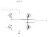
- FIG. 3 is a diagram showing the inverter unit of the power transmission system of the embodiment of the present invention.
- the inverter unit 130 includes four field-effect transistors (FETs) Q A to Q D , which are connected by a full bridge method.
- FETs field-effect transistors
- the power-transmission antenna 140 is connected between a connection section T1, which is between the switching elements Q A and Q B that are connected in series, and a connection section T2, which is between the switching elements Q C and Q D that are connected in series.
- a connection section T1 which is between the switching elements Q A and Q B that are connected in series
- a connection section T2 which is between the switching elements Q C and Q D that are connected in series.
- a drive signal for the switching elements Q A to Q D that constitute the above inverter unit 130 is input from the power-transmission control unit 150.
- a frequency that is used to drive the inverter unit 130 can be controlled from the power-transmission control unit 150.
- the power-transmission antenna 140 includes a coil described later, which includes an inductance component.
- the power-transmission antenna 140 resonates with the power-reception antenna 210, which is mounted on a vehicle in such a way as to face the power-transmission antenna 140. Therefore, electric energy that is output from the power-transmission antenna 140 can be transmitted to the power-reception antenna 210.
- impedance-matching may be carried out once by a matching box, which is not shown in the diagrams.
- the matching box can include a passive element having a predetermined circuit constant.
- a resonance frequency of the power-transmission antenna 140 is equal to a resonance frequency of the power-reception antenna 210. Therefore, from the power-transmission-side antenna to the power-reception-side antenna, energy is transmitted efficiently.
- Voltage V 1 and current I 1 which are input into the inverter unit 130, and voltage V 2 and current I 2 , which are output from the inverter unit 130, are measured by the power-transmission control unit 150.
- the power-transmission control unit 150 includes general-purpose information processing units, such as a CPU, a ROM that holds a program running on the CPU, and a RAM that serves as a work area of the CPU.
- the power-transmission control unit 150 calculates efficiency (W 1 /W 2 ) of the inverter unit 130 from the acquired input power (W 1 ) and output power (W 2 ).
- a storage unit 151 of the power-transmission control unit 150 is a temporary storage means for storing a frequency and the calculated inverter efficiency in such a way that the frequency and the calculated inverter efficiency are associated with each other when sweeping of frequencies is carried out.
- the power-transmission control unit 150 performs a control process in such a way that the output power of the inverter unit 130 becomes a predetermined power.
- the power-transmission control unit 150 calculates the inverter efficiency of the inverter unit 130, while changing the frequency of the AC voltage output by the inverter unit 130, to store in the storage unit 151.
- the power-transmission control unit 150 controls the voltage of the DC voltage output by the rectification booster unit 120, and the frequency of the AC voltage output by the inverter unit 130 to actually transmit power for charging.
- the power-reception antenna 210 resonates with the power-transmission antenna 140, thereby receiving electric energy output from the power-transmission antenna 140.
- the AC power received by the power-reception antenna 210 is rectified in a rectifier 220.
- the rectified power is accumulated in a battery 240 via a charger 230.
- the charger 230 controls charging of the battery 240.
- the battery 240 is used as a load of the power-reception-side system, and the battery 240 is charged.
- another load may be used as a load of the power-reception-side system.
- Voltage V 3 and current I 3 which are input from the charger 230 to the battery 240, are measured by the charging control unit 250. Based on the measured voltage V 3 and current I 3 , the charging control unit 250 is so designed as to be able to control the charger 230, and control charging of the battery 240 in accordance with an appropriate charging profile of the battery 240.
- the charger 230 can select a constant current, constant output, or constant voltage to charge the battery 240.
- the charging control unit 250 includes general-purpose information processing units, such as a CPU, a ROM that holds a program running on the CPU, and a RAM that serves as a work area of the CPU.
- the charging control unit 250 runs in such a way as to work together with each component that is shown in the diagrams and is connected to the charging control unit 250.
- the charging control unit 250 stores the charging profile of the battery 240, as well as algorithm for enabling the charging control unit 250 to operate in accordance with the profile.
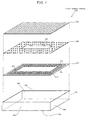
- FIG. 4 is an exploded perspective view of the power-reception antenna 210 used in the power transmission system of the embodiment of the present invention.
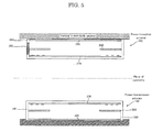
- FIG. 5 is a schematic cross-sectional view showing how power is transmitted between the antennas in power transmission of the embodiment of the present invention.
- a rectangular flat-plate coil body is used as a coil body 270.
- an antenna of the present invention is not limited to a coil of such a shape.
- a circular flat-plate coil body or the like may be used as the coil body 270.
- the coil body 270 functions as a magnetic resonance antenna section of the power-reception antenna 210.
- the "magnetic resonance antenna section" includes not only an inductance component of the coil body 270, but also a capacitance component that is based on stray capacitance thereof, or a capacitance component that is based on an intentionally added capacitor.
- a coil case 260 is used to house the coil body 270, which includes an inductance component of the power-reception antenna 210.
- the coil case 260 is of a box shape with an opening, and is made of resin such as polycarbonate. From each side of a rectangular bottom plate section 261 of the coil case 260, a side plate section 262 is so provided as to extend in a vertical direction with respect to the bottom plate section 261. In an upper section of the coil case 260, an upper opening section 263 is so provided as to be surrounded by the side plate sections 262.
- the power-reception antenna 210 packaged in the coil case 260 is mounted on a vehicle' s main body section in such a way that the upper opening section 263 faces the vehicle's main body section.
- any conventional known method can be used.
- a flange member or the like may be used around the upper opening section 263.
- the coil body 270 includes a rectangular flat-plate substrate 271, which is made of glass epoxy, and a spiral conductive section 272, which is formed on the substrate 271.
- An inner-peripheral-side first end section 273 of the spiral conductive section 272, and an outer-peripheral-side second end section 274 are electrically connected to a conductive line (not shown). Therefore, power received by the power-reception antenna 210 can be led to a rectification unit 202.
- the above coil body 270 is placed on the rectangular bottom plate section 261 of the coil case 260, and is fixed onto the bottom plate section 261 by using an appropriate fixing means.
- a magnetic shielding body 280 is a flat-plate magnetic member having a hollow section 285.
- a substance that is high in specific resistance, high in magnetic permeability, and small in magnetic hysteresis is desirable; for example, a magnetic material such as ferrite can be used.
- the magnetic shielding body 280 is fixed to the coil case 260 by using an appropriate means. Above the coil body 270, the magnetic shielding body 280 is disposed with a certain amount of space therebetween. Because of such a layout, magnetic field lines that are generated at the power-transmission antenna 140 have a high possibility of penetrating the magnetic shielding body 280. In transmitting power from the power-transmission antenna 140 to the power-reception antenna 210, an impact of metal objects that constitute the vehicle's main body section on the magnetic field lines becomes insignificant.
- a rectangular flat-plate metal lid section 290 is disposed above the shielding body 280 with a predetermined distance therebetween in such a way as to cover the upper opening section 263.
- any metal material can be used. According to the present embodiment, for example, aluminum is used.
- the magnetic shielding body 280 is provided above the coil body 270. Therefore, even if the power-reception antenna 210 is mounted on the bottom surface of the vehicle, it is possible to curb the influence of metal objects and the like that constitute the vehicle's main body section, and to transmit power efficiently.
- the above configuration of the power-reception antenna 210 is also applied to the power-transmission-side antenna that constitutes the power transmission system 100.
- the power-transmission antenna 105 is plane-symmetrical (mirror-image symmetrical) to the power-reception antenna 210 with respect to a horizontal plane.
- a coil body 370 is placed in a coil case 360, and a magnetic shielding body 380 is provided a predetermined distance away therefrom.
- a metal lid section 390 is used to seal the coil case 260.
- the following describes transmission of power by the power transmission system 100 of the present embodiment with the above configuration.
- frequency-sweeping is carried out by power used for the power transmission, thereby selecting an extreme value of inverter efficiency; based on the extreme value, a frequency is determined to drive the inverter unit 130 for actual power transmission.
- a frequency is determined to drive the inverter unit 130 for actual power transmission.
- an optimal frequency is selected as described above, and then power is transmitted by using the selected optimal frequency.
- FIG. 6 is a diagram showing a flowchart of the power transmission process in the power transmission system of the embodiment of the present invention. The flowchart is performed by the power-transmission control unit 150.
- the power-transmission control unit 150 at the subsequent step S101 sets the rectification booster unit 120 in such a way that a target output value becomes a predetermined power value.
- a drive frequency of the inverter unit 130 is set to a lower-limit value for sweeping.
- step S103 power is transmitted by first power.
- step S104 V 1 , I 1 , V 2 , and I 2 are measured to measure the input power (W 1 ) and the output power (W 2 ).
- the calculated inverter efficiency and the frequency are stored in the storage unit 151 in such a way as to be associated with each other.
- the inverter efficiency is calculated with varying frequencies.
- frequency characteristics of the inverter efficiency are accumulated.
- step S107 a determination is made as to whether or not the set frequency is greater than or equal to an upper-limit frequency for sweeping. If the determination of step S107 is NO, the process proceeds to step S110; after the frequency is increased by a predetermined amount and is set, the process returns to step S103 and enters a loop.
- step S107 If the determination of step S107 is YES, all the frequencies have been swept. Therefore, the process proceeds to step S108, and, from the frequency characteristics stored in the storage unit 151, a frequency that gives an extreme value of inverter efficiency is selected.
- FIG. 7 is a diagram showing relationship between frequency and power transmission efficiency in the power transmission system of the present embodiment.
- FIG. 7A shows frequency characteristics of power transmission efficiency in a situation where the power-reception antenna 210 and the power-transmission antenna 140 are most appropriately disposed. As shown in FIG. 7A , there are two frequencies giving two extreme values; the extreme-value frequency of a lower frequency is defined as a first extreme-value frequency, and the extreme-value frequency of a higher frequency as a second extreme-value frequency.
- FIGS. 7A, 7B, 7C, and 7D show frequency characteristics of power transmission efficiency: Moving from FIG. 7A to FIG. 7B , and then to FIGS. 7C and 7D , a position gap between the power-reception antenna 210 and the power-transmission antenna 140 becomes larger.
- the frequency of the extreme value is selected at step S108.
- the frequency of the extreme value is selected at step S108.
- the first and second extreme-value frequencies what is selected according to the present embodiment is an extreme-value frequency that generates an electric wall on a plane of symmetry between the power-transmission antenna 140 and the power-reception antenna 210.
- the following describes the concept of an electric wall and magnetic wall that are generated on a plane of symmetry between the power-transmission antenna 140 and the power-reception antenna 210.
- FIG. 8 is a diagram schematically showing the state of current and electric fields at the first extreme-value frequency.
- the phase of the current flowing through the power-transmission antenna 140 is substantially equal to the phase of the current flowing through the power-reception antenna 210.
- a position where magnetic field vectors are aligned is near the central sections of the power-transmission antenna 140 and power-reception antenna 210.
- a magnetic wall is considered to be generated: a magnetic field of the magnetic wall is vertical with respect to a plane of symmetry between the power-transmission antenna 140 and the power-reception antenna 210.
- FIG. 9 is a diagram schematically showing the state of current and electric fields at the second extreme-value frequency.
- the phase of the current flowing through the power-transmission antenna 140 is substantially opposite to the phase of the current flowing through the power-reception antenna 210.
- a position where magnetic field vectors are aligned is near a plane of symmetry between the power-transmission antenna 140 and the power-reception antenna 210.
- an electric wall is considered to be generated: a magnetic field of the electric wall is horizontal with respect to a plane of symmetry between the power-transmission antenna 140 and the power-reception antenna 210.
- FIG. 10 is a diagram showing characteristics at an extreme-value frequency (first frequency) that generates a magnetic wall, among extreme-value frequencies that give two extreme values.
- FIG. 10A is a diagram showing how the power-transmission-side voltage (V 1 ) and current (I 1 ) change as a load of the battery 240 (load) is changed and varied.
- FIG. 10B is a diagram showing how the power-reception-side voltage (V 3 ) and current (I 3 ) change as a load of the battery 240 (load) is changed and varied. According to the characteristics shown in FIG. 10 , it is clear that, as the load of the battery 240 (load) is increased at the power reception side, the voltage becomes higher.
- the power-reception antenna 210 works as a constant current source.
- the voltage of both end sections of the power-reception antenna 210 would rise.
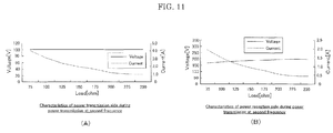
- FIG. 11 is a diagram showing characteristics at an extreme-value frequency (second frequency) that generates an electric wall, among extreme-value frequencies that give two extreme values.
- FIG. 11A is a diagram showing how the power-transmission-side voltage (V 1 ) and current (I 1 ) change as a load of the battery 240 (load) is changed and varied.
- FIG. 11B is a diagram showing how the power-reception-side voltage (V 3 ) and current (I 3 ) change as a load of the battery 240 (load) is changed and varied. According to the characteristics shown in FIG. 11 , it is clear that, as the load of the battery 240 (load) is increased at the power reception side, the current becomes smaller.
- the power-reception antenna 210 works as a constant voltage source.
- the voltage of both end sections of the power-reception antenna 210 does not rise. Therefore, in the power transmission system of the present invention, the voltage does not become higher when the load drops sharply. It is possible to transmit power in a stable manner.
- the charging circuit works as a current source.
- the characteristics of FIG. 11 to the power-reception-side battery 240 (load), it seems that the charging circuit works as a voltage source.
- the characteristics shown in FIG. 11 of decreasing current are more preferred for the battery 240 (load).
- an extreme-value frequency that generates an electric wall on a plane of symmetry between the power-transmission antenna 140 and the power-reception antenna 210 is selected.
- the power transmission system of the present invention can determine, even when there are two frequencies that give extreme values of transmission efficiency, an optimal frequency for power transmission, and can transmit power efficiently.
- the advantage is that it is easy to handle because, when an output to the battery 240 is changed, an output of the inverter unit 130 is increased or decreased accordingly by the charging control. Moreover, the supplied power is automatically minimized when the charger 230 is stopped in an urgent manner, thereby eliminating the need for useless devices.
- the charger 230 In the case where there are two frequencies that give two extreme values, if an extreme-value frequency that generates an electric wall on a plane of symmetry between the power-transmission antenna 140 and the power-reception antenna 210 is selected, it seems to the charger 230 that the rectifier 220 works as a voltage source. Therefore, the advantage is that it is easy to handle because, when an output to the battery 240 is changed, an output of the rectification booster unit 120 is increased or decreased accordingly by the charging control. Moreover, the supplied power is automatically minimized when the charger 230 is stopped in an urgent manner, thereby eliminating the need for useless devices.
- step S109 power is transmitted at the optimal frequency selected at step S108.
- the power transmission system of the present invention can determine an optimal frequency for power transmission, and transmit power efficiently.
- the power transmission system of the present invention is suitable for use in a system that charges vehicles such as electric vehicles (EV) and hybrid electric vehicles (HEV), which have increasingly become popular in recent years.
- a frequency at which a reception antenna works as a constant current source and a frequency at which the reception antenna works as a constant voltage source exist. If the frequency at which the reception antenna works as a constant current source is used, a voltage of a reception antenna' s end portion might become higher when an emergency shutdown occurs due to a load side.
- a frequency is so selected that the reception antenna seems to work as a constant voltage source, before power is transmitted. Therefore, it is possible to transmit power in a stable manner without sending the voltage higher when the load drops sharply. As a result, industrial applicability is very high.
Landscapes
- Engineering & Computer Science (AREA)
- Power Engineering (AREA)
- Mechanical Engineering (AREA)
- Transportation (AREA)
- Computer Networks & Wireless Communication (AREA)
- Life Sciences & Earth Sciences (AREA)
- Sustainable Development (AREA)
- Sustainable Energy (AREA)
- Physics & Mathematics (AREA)
- Electromagnetism (AREA)
- Charge And Discharge Circuits For Batteries Or The Like (AREA)
- Electric Propulsion And Braking For Vehicles (AREA)
- Current-Collector Devices For Electrically Propelled Vehicles (AREA)
- Secondary Cells (AREA)
Applications Claiming Priority (2)
| Application Number | Priority Date | Filing Date | Title |
|---|---|---|---|
| JP2011079035A JP2012217228A (ja) | 2011-03-31 | 2011-03-31 | 電力伝送システム |
| PCT/JP2012/002122 WO2012132413A1 (fr) | 2011-03-31 | 2012-03-27 | Système de transmission de puissance |
Publications (1)
| Publication Number | Publication Date |
|---|---|
| EP2693600A1 true EP2693600A1 (fr) | 2014-02-05 |
Family
ID=46930187
Family Applications (1)
| Application Number | Title | Priority Date | Filing Date |
|---|---|---|---|
| EP12763849.2A Withdrawn EP2693600A1 (fr) | 2011-03-31 | 2012-03-27 | Système de transmission de puissance |
Country Status (5)
| Country | Link |
|---|---|
| US (1) | US20140239728A1 (fr) |
| EP (1) | EP2693600A1 (fr) |
| JP (1) | JP2012217228A (fr) |
| CN (1) | CN103460555A (fr) |
| WO (1) | WO2012132413A1 (fr) |
Cited By (3)
| Publication number | Priority date | Publication date | Assignee | Title |
|---|---|---|---|---|
| EP2985873A4 (fr) * | 2013-03-27 | 2016-06-15 | Panasonic Ip Man Co Ltd | Dispositif d'alimentation de puissance, dispositif de réception de puissance, et système de charge |
| EP3157136A1 (fr) * | 2015-10-02 | 2017-04-19 | Panasonic Intellectual Property Management Co., Ltd. | Système de transmission d'énergie sans fil |
| WO2017184268A1 (fr) * | 2016-04-20 | 2017-10-26 | Qualcomm Incorporated | Systèmes et procédés pour l'identification d'une fréquence de fonctionnement idéale pour un transfert de puissance sans fil |
Families Citing this family (10)
| Publication number | Priority date | Publication date | Assignee | Title |
|---|---|---|---|---|
| JP6420025B2 (ja) * | 2013-03-08 | 2018-11-07 | マクセルホールディングス株式会社 | 非接触電力伝送装置及び非接触電力伝送方法 |
| JP6097102B2 (ja) * | 2013-03-12 | 2017-03-15 | 国立大学法人埼玉大学 | 磁気浮上装置 |
| JP6169380B2 (ja) * | 2013-03-19 | 2017-07-26 | 日東電工株式会社 | 無線電力伝送装置、無線電力伝送装置の発熱制御方法、及び、無線電力伝送装置の製造方法 |
| DE102013210411A1 (de) * | 2013-06-05 | 2014-12-11 | Robert Bosch Gmbh | Spulenvorrichtung und Verfahren zur induktiven Leistungsübertragung |
| JP6249205B2 (ja) * | 2013-07-01 | 2017-12-20 | パナソニックIpマネジメント株式会社 | 給電装置及び給電装置の制御方法 |
| JP2015012748A (ja) * | 2013-07-01 | 2015-01-19 | パナソニックIpマネジメント株式会社 | 給電装置及び周波数特性取得方法 |
| KR20160100755A (ko) | 2015-02-16 | 2016-08-24 | 엘지이노텍 주식회사 | 무선전력 송신장치 및 송신방법 |
| JP6458678B2 (ja) * | 2015-08-05 | 2019-01-30 | トヨタ自動車株式会社 | コイルユニット |
| CN107370245A (zh) * | 2017-07-13 | 2017-11-21 | 上海交通大学 | 一种集成式无线充电线圈及其电能传输系统 |
| JP6904280B2 (ja) | 2018-03-06 | 2021-07-14 | オムロン株式会社 | 非接触給電装置 |
Family Cites Families (7)
| Publication number | Priority date | Publication date | Assignee | Title |
|---|---|---|---|---|
| WO2007008646A2 (fr) | 2005-07-12 | 2007-01-18 | Massachusetts Institute Of Technology | Transfert d'energie non radiatif sans fil |
| US8164925B2 (en) * | 2005-09-01 | 2012-04-24 | National University Corporation Saitama University | Non-contact power feeder |
| NZ565234A (en) * | 2008-01-18 | 2010-11-26 | Telemetry Res Ltd | Selectable resonant frequency transcutaneous energy transfer system |
| US8421267B2 (en) * | 2008-03-10 | 2013-04-16 | Qualcomm, Incorporated | Packaging and details of a wireless power device |
| JP5288958B2 (ja) | 2008-09-11 | 2013-09-11 | 矢崎総業株式会社 | ワイヤレス電力送信装置及び共鳴周波数調整方法 |
| JP5621203B2 (ja) * | 2009-03-30 | 2014-11-12 | 富士通株式会社 | 無線電力供給システム、無線電力供給方法 |
| JP5417942B2 (ja) * | 2009-03-31 | 2014-02-19 | 富士通株式会社 | 送電装置、送受電装置および送電方法 |
-
2011
- 2011-03-31 JP JP2011079035A patent/JP2012217228A/ja active Pending
-
2012
- 2012-03-27 CN CN201280015504XA patent/CN103460555A/zh active Pending
- 2012-03-27 WO PCT/JP2012/002122 patent/WO2012132413A1/fr active Application Filing
- 2012-03-27 EP EP12763849.2A patent/EP2693600A1/fr not_active Withdrawn
- 2012-03-27 US US14/008,855 patent/US20140239728A1/en not_active Abandoned
Non-Patent Citations (1)
| Title |
|---|
| See references of WO2012132413A1 * |
Cited By (5)
| Publication number | Priority date | Publication date | Assignee | Title |
|---|---|---|---|---|
| EP2985873A4 (fr) * | 2013-03-27 | 2016-06-15 | Panasonic Ip Man Co Ltd | Dispositif d'alimentation de puissance, dispositif de réception de puissance, et système de charge |
| US9815380B2 (en) | 2013-03-27 | 2017-11-14 | Panasonic Intellectual Property Management Co., Ltd. | Power supply device, power receiving device, and charging system |
| EP3157136A1 (fr) * | 2015-10-02 | 2017-04-19 | Panasonic Intellectual Property Management Co., Ltd. | Système de transmission d'énergie sans fil |
| WO2017184268A1 (fr) * | 2016-04-20 | 2017-10-26 | Qualcomm Incorporated | Systèmes et procédés pour l'identification d'une fréquence de fonctionnement idéale pour un transfert de puissance sans fil |
| US10000133B2 (en) | 2016-04-20 | 2018-06-19 | Qualcomm Incorporated | Systems and methods for identifying an ideal operation frequency for wireless power transfer |
Also Published As
| Publication number | Publication date |
|---|---|
| WO2012132413A1 (fr) | 2012-10-04 |
| US20140239728A1 (en) | 2014-08-28 |
| JP2012217228A (ja) | 2012-11-08 |
| CN103460555A (zh) | 2013-12-18 |
Similar Documents
| Publication | Publication Date | Title |
|---|---|---|
| EP2693600A1 (fr) | Système de transmission de puissance | |
| EP2833509A1 (fr) | Système de transmission électrique | |
| US9270138B2 (en) | Electric power transmission system | |
| US20140111022A1 (en) | Power transmission system | |
| Imura et al. | Maximizing air gap and efficiency of magnetic resonant coupling for wireless power transfer using equivalent circuit and Neumann formula | |
| EP2773019B1 (fr) | Appareil de réception d'énergie sans contact | |
| Kim et al. | Optimal design of a wireless power transfer system with multiple self-resonators for an LED TV | |
| US8519569B2 (en) | Wireless power supply system and wireless power supply method | |
| EP2889177B1 (fr) | Transmission d'énergie sans fil dans des véhicules électriques | |
| EP2824797A1 (fr) | Système de transmission de puissance | |
| EP2848453B1 (fr) | Véhicule comprenant bobine de réception d'énergie | |
| JP5924496B2 (ja) | 電力伝送システム | |
| CN102714431A (zh) | 非接触送电系统 | |
| JP2011155732A (ja) | 非接触送電システム、および非接触送電装置 | |
| JP2013211933A (ja) | 電力伝送システム | |
| EP3082223B1 (fr) | Système de transmission d'énergie sans contact et dispositif de transmission électrique | |
| JP2013135491A (ja) | アンテナ | |
| JP2013132141A (ja) | 電力伝送システム | |
| JP2013027082A (ja) | 電力伝送システム | |
| JP2014197935A (ja) | 電力伝送システム | |
| JP2014093320A (ja) | 電力伝送システム | |
| JP2013027081A (ja) | 電力伝送システム | |
| JP2014093798A (ja) | 電力伝送システム | |
| JP2014093796A (ja) | 電力伝送システム |
Legal Events
| Date | Code | Title | Description |
|---|---|---|---|
| PUAI | Public reference made under article 153(3) epc to a published international application that has entered the european phase |
Free format text: ORIGINAL CODE: 0009012 |
|
| 17P | Request for examination filed |
Effective date: 20130930 |
|
| AK | Designated contracting states |
Kind code of ref document: A1 Designated state(s): AL AT BE BG CH CY CZ DE DK EE ES FI FR GB GR HR HU IE IS IT LI LT LU LV MC MK MT NL NO PL PT RO RS SE SI SK SM TR |
|
| STAA | Information on the status of an ep patent application or granted ep patent |
Free format text: STATUS: THE APPLICATION HAS BEEN WITHDRAWN |
|
| 18W | Application withdrawn |
Effective date: 20140312 |