EP2693019A1 - Mobile operating machine having hybrid driving system - Google Patents
Mobile operating machine having hybrid driving system Download PDFInfo
- Publication number
- EP2693019A1 EP2693019A1 EP12764283.3A EP12764283A EP2693019A1 EP 2693019 A1 EP2693019 A1 EP 2693019A1 EP 12764283 A EP12764283 A EP 12764283A EP 2693019 A1 EP2693019 A1 EP 2693019A1
- Authority
- EP
- European Patent Office
- Prior art keywords
- engine
- human
- work machine
- electric motor
- motor
- Prior art date
- Legal status (The legal status is an assumption and is not a legal conclusion. Google has not performed a legal analysis and makes no representation as to the accuracy of the status listed.)
- Granted
Links
Images



Classifications
-
- B—PERFORMING OPERATIONS; TRANSPORTING
- B25—HAND TOOLS; PORTABLE POWER-DRIVEN TOOLS; MANIPULATORS
- B25F—COMBINATION OR MULTI-PURPOSE TOOLS NOT OTHERWISE PROVIDED FOR; DETAILS OR COMPONENTS OF PORTABLE POWER-DRIVEN TOOLS NOT PARTICULARLY RELATED TO THE OPERATIONS PERFORMED AND NOT OTHERWISE PROVIDED FOR
- B25F5/00—Details or components of portable power-driven tools not particularly related to the operations performed and not otherwise provided for
-
- H—ELECTRICITY
- H02—GENERATION; CONVERSION OR DISTRIBUTION OF ELECTRIC POWER
- H02K—DYNAMO-ELECTRIC MACHINES
- H02K7/00—Arrangements for handling mechanical energy structurally associated with dynamo-electric machines, e.g. structural association with mechanical driving motors or auxiliary dynamo-electric machines
- H02K7/14—Structural association with mechanical loads, e.g. with hand-held machine tools or fans
- H02K7/145—Hand-held machine tool
-
- H—ELECTRICITY
- H02—GENERATION; CONVERSION OR DISTRIBUTION OF ELECTRIC POWER
- H02K—DYNAMO-ELECTRIC MACHINES
- H02K7/00—Arrangements for handling mechanical energy structurally associated with dynamo-electric machines, e.g. structural association with mechanical driving motors or auxiliary dynamo-electric machines
- H02K7/18—Structural association of electric generators with mechanical driving motors, e.g. with turbines
- H02K7/1807—Rotary generators
Definitions
- the present teachings relates to a human-carried, e.g. a hand-held or shoulder-held work machine.
- JP2010-84673A discloses a mower.
- the mower is a kind of a human-carried work machine powered by an engine, more specifically is provided with the engine as a prime mover for driving a mowing blade.
- the present description provides teachings which enable to increase an output of a human-carried work machine without needing the engine with increased displacement.
- both of an engine and an electric motor are used as a prime mover to drive a tool.
- the electric motor being installed in addition to the engine in the configuration, an output of a work machine can be increased even though a size of the engine is identical to that of a conventional engine. Hence, an engine with large displacement amount is not required. Since there is no need to newly develop an engine with large displacement, a high power human-carried work machine can be realized without spending a lot of time and cost for the development.
- an engine includes an output shaft (for example, crankshaft) connected to a tool and an electric motor is configured to apply torque to the output shaft of the engine.
- an output shaft for example, crankshaft
- an electric motor is configured to apply torque to the output shaft of the engine.
- the electric motor is fixed to the output shaft of the engine and includes a rotor that is provided with at least one magnet.
- the rotor is provided with a cooling fan that is configured to send cooling air to the engine.
- the electric motor includes a stator core that is fixed to a case (including a crankcase or a cylinder block) of the engine and faces the magnet of the rotor.
- the rotor includes a peripheral wall that surrounds the stator core, and the magnet is disposed on an inner surface of the peripheral wall.
- the electric motor is configured to further function as an electric generator. According to the configuration, when there is an allowance in an output of the engine, electric energy can be stored. Alternatively, an increase in an energy efficiency and a reduction in a carbon dioxide emission amount can be achieved by performing regenerative braking for the tool.
- the human-carried work machine further includes an operable portion that is configured to be operated by a user to adjust the output of the engine.
- the electric motor is configured to serve as the electric generator, and when the amount of operation applied to the operable portion is more than a second predetermined amount, the electric motor is configured to serve as the prime mover for driving the tool.
- the electric motor is configured to function as a "cell" motor (starter motor) for starting the engine. That is, it is preferable that the electric motor rotates the engine by applying the torque to the crankshaft when the user starts the engine (that is, when the user operates a starter switch). According to the configuration, the user can easily start the engine.
- the human-carried work machine may be any of a mower, a weeder, a chain saw, a circular cutter (cut-off saw), a sprayer, a duster, a blower, or a dust collector.
- the tools of the human-carried work machine include not only cutters of a moving blade, a saw chain and the like but a blowing fan and a pump.
- the human-carried work machines are not limited to the examples described above but widely include work machines which the user carries to perform operations.
- the engine for driving the tool may be either of a two stroke engine or a four stroke engine.
- the engine may be an engine of other style (typically, internal combustion engine).
- the style of the engine is not particularly limited.
- the electric motor for driving the tool may be either of a motor with a brush or a brushless motor.
- the electric motor may be an electric motor of other style (typically, direct current motor).
- the style of the electric motor is not particularly limited. However, in a human-carried work machine which utilizes a combustible fuel, it is preferable to adopt a brushless motor which does not need a contact type commutator.
- the human-carried work machine includes an electric power storage and electric power stored to the electric power storage is supplied to the electric motor.
- the electric power generated by the electric motor is supplied to the electric power storage to store.
- the electric power storage can adopt a battery pack that incorporates multiple secondary battery cells.
- the secondary battery cell is a lithium ion cell.
- a battery pack developed for an electric power tool can be preferably employed.
- the battery pack developed for the electric power tool particularly, the battery pack that includes the lithium ion cell has a large capacity, and can discharge a large current. Consequently, the engine can sufficiently be assisted by the motor and the electric power that is generated by the motor can be stored by a large amount by adopting such a battery pack. Consequently, it is preferable that the human-carried work machine includes a battery attaching portion that attachably and detachably receives the battery pack (for example, a battery pack of a slidingly attachable and detachable type) that is developed for the electric power tool.
- the human-carried work machine performs idling stop. That is, it is preferable to automatically stop and start the engine in accordance with an operation of a throttle lever or a lock-off release switch by the user.
- FIG. 1 shows an external appearance of a mower 2 of an embodiment.
- the mower 2 is an example of a human-carried work machine.
- the mower 2 is provided with an operation rod 4, a power unit 6 attached to a rear end portion of the operation rod 4, a gear head 8 attached to a front end portion of the operation rod 4, a mowing blade 10 in a circular disk shape attached to the gear head 8, a safety cover 12 attached to the front end portion of the operation rod 4 to cover the mowing blade 10, and a handle 14 attached to a middle portion of the operation rod 4.
- the operation rod 4 is formed in a hollow pipe shape, and extended linearly.
- a drive shaft (not illustrated) is contained at inside of the operation rod 4. Torque outputted from the power unit 6 is transmitted to the gear head 8 via the drive shaft at inside of the operation rod 4 to rotate the mowing blade 10.
- the handle 14 is provided with a throttle lever 16 which performs a throttle operation of an engine 20 described later, and a stop switch (not illustrated) for stopping the engine 20.
- the throttle lever 16 is an operable portion operated by a user for adjusting an output of the engine.
- the power unit 6 is provided with the engine 20, a fuel tank 22 for storing fuel of the engine 20, a recoil starter 26 for starting the engine 20, an air cleaner 28 for filtering air supplied to the engine 20, a carburetor 30 for mixing fuel to the supplied air, and a muffler 32 for discharging exhaust gas from the engine 20 to the atmosphere.
- the carburetor 30 is connected to the throttle lever 16, and a throttle position of the carburetor 30 is changed in accordance with an operation of the throttle lever 16.
- the engine 20 is a four stroke engine of a separate oiling system.
- the engine 20 is provided with a cylinder 34, a piston 38 accommodated in the cylinder 34, an ignition plug 36 provided at the cylinder 34, a crankcase 40, a crankshaft 42 accommodated in the crankcase 40, and an oil pan 24.
- the crankshaft 42 is an output shaft of the engine 20, and connected to the drive shaft via a centrifugal clutch (not illustrated). Thereby, the output of the engine 20 is transmitted to the mowing blade 10 through the drive shaft. That is, the engine 20 is a prime mover for driving the mowing blade 10.
- the power unit 6 is further provided with a motor 50.
- the motor 50 is a brushless three phase motor of an outer rotor type.
- the motor 50 is provided with stator cores 52, stator coils 54, an outer rotor 58, and magnets 56.
- the stator core 52 is formed by a magnetic material, and is fixed to the crankcase 40.
- the stator coil 54 is wound around the stator core 52 and excites the stator core 52 when electricity is conducted.
- the outer rotor 58 is fixed to the crankshaft 42, and is rotated along with the crankshaft 42.
- the outer rotor 58 is formed in a cup-like shape having a peripheral wall in a circular cylinder shape and a bottom wall provided to one end of the peripheral wall, and the peripheral wall surrounds the stator core 52.
- the magnets 56 are fixed to an inner peripheral face of the outer rotor 58, and face the stator cores 52 disposed inside the outer rotor 58.
- the motor 50 is a second prime mover for driving the mowing blade 10.
- the mower 2 of the embodiment is a human-carried work machine of a hybrid type having different kinds of the prime movers of the engine 20 and the motor 50.
- the engine 20 of the embodiment is an engine having the displacement of 25 cc (25 milliliters), and has an output of about 700 watts.
- the motor 50 has an output of about 650 watts.
- a combination of the engine 20 and the motor 50 has an output of about 1350 watts, and the value corresponds to a 4 stroke engine having the displacement of 45 cc (45 milliliters).
- an output equivalent to that of an engine having a large displacement can be realized by combining the engine 20 and the motor 50, while using the engine 20 having a small displacement.
- the motor 50 can function also as a generator for converting rotational energy of the crankshaft 42 to electric energy. For example, when there is an allowance in the output of the engine 20, a portion of the output of the engine 20 is converted into electric power by the motor 50. The electric power generated by the motor 50 is stored to a battery pack 90 described later.
- the motor 50 can function as a "cell" motor (starter motor) for starting the engine 20.
- start motor starter motor
- the motor 50 rotates the crankshaft 42. Thereby, the engine 20 is started.
- the outer rotor 58 of the motor 50 is integrally provided with a cooling fan 60.
- the cooling fan 60 is provided at an outer peripheral face of the peripheral wall of the outer rotor 58.
- the cooling fan 60 is configured to fan the engine 20, the motor 50, and a controller unit 70 to cool.
- a position of arranging the motor 50 is a position at which a cooling fan is arranged in a conventional product. An enlargement of a size from that of the conventional product and a change in design are restrained by integrally forming the cooling fan 60 and the outer rotor 58.
- FIG 4 is a block diagram showing an electric configuration of the power unit 6.
- the power unit 6 is provided with the controller unit 70, and the battery pack 90 connected to the controller unit 70.
- the controller unit 70 is configured by multiple integrated circuits including a microcomputer.
- the controller unit 70 is a control portion for controlling operations of the engine 20 and the motor 50.
- the battery pack 90 contains multiple secondary battery cells, and supplies electric power to the motor 50 and the ignition plug 36 via the controller unit 70.
- the battery pack 90 of the embodiment is a battery pack containing a lithium ion cell, and having a nominal voltage of 18 volts.
- the controller unit 70 is functionally provided with an engine igniter circuit 72, an ignition timing detector circuit 74, a throttle position detector circuit 76, a rotor position detector circuit 78, and a motor driver circuit 80.
- the engine igniter circuit 72 supplies the electric power from the battery pack 90 to the ignition plug 36. At this time, the electric power from the battery pack 90 is boosted in voltage by the ignition coil 64. An electric discharge is produced by the ignition plug 36 and an ignition to an air fuel mixture is carried out.
- the ignition timing detector circuit 74 determines ignition timing of the ignition plug 36 while detecting a rotational position of the crankshaft 42. The determined ignition timing is taught to the engine igniter circuit 72.
- the throttle position detector circuit 76 is connected to the carburetor 30, and detects a throttle position of the carburetor 30. Incidentally, the throttle position detector circuit 76 may detect an operation amount of the throttle lever 16 by the user in place of the throttle position of the carburetor 30.
- the rotor position detector circuit 78 is connected to an encoder 66 of the motor 50, and detects a rotational position of the outer rotor 58.
- the motor driver circuit 80 is provided with multiple plural switching elements, and selectively connects respective phases of the stator coils 54 and respective electrodes of the battery pack 90 in accordance with the detected rotational position of the outer rotor 58.
- the motor driver circuit 80 can perform a PWM control of the motor 50 and can control the output of the motor 50 in accordance with the detected throttle position of the carburetor 30.
- the motor driver circuit 80 can make the motor 50 function as the generator by changing switching modes of the multiple switching elements. Thereby, the battery pack 90 can be charged. That is, the motor driver circuit 80 functions also as the battery charge circuit.
- the controller unit 70 makes the motor 50 function as the generator and charges the battery pack 90 by the output of the engine 20.
- the controller unit 70 does not make the motor 50 function also as the generator and does not make the motor 50 function also as the prime mover.
- the controller unit 70 makes the motor 50 function as the prime mover, and assists a deficient output of the engine 20 by the motor 50.
- a large amount of the growth of weeds can strongly be mown by driving the mowing blade 10 by both of the engine 20 and the motor 50.
- a rotational frequency of the engine may be more than a predetermined value (for example, rotational frequency achieving maximum output), and at this time, it can be said that there is the allowance in the output of the engine. Consequently, when the rotational frequency of the engine is more than the predetermined value (particularly, the rotational frequency achieving the maximum output), it is preferable that the controller unit 70 makes the motor 50 function as the generator and charges the battery pack 90 by the output of the engine 20.
- the controller unit 70 stops feeding electricity to the ignition plug 36 and stops the engine 20. This is so-called idling stop. Thereafter, when the user operates the throttle lever 16, the controller unit 70 drives the crankshaft 42 by the motor 50 and restarts the engine 20. An energy consumption amount and an exhaust gas emission amount are reduced by avoiding useless idling.
Landscapes
- Engineering & Computer Science (AREA)
- Power Engineering (AREA)
- Mechanical Engineering (AREA)
- Harvester Elements (AREA)
- Connection Of Motors, Electrical Generators, Mechanical Devices, And The Like (AREA)
Abstract
Description
- The present teachings relates to a human-carried, e.g. a hand-held or shoulder-held work machine.
-
JP2010-84673A - There is a need for high output in a human-carried work machine to improve work efficiency. On account of this, efforts have been made to develop an engine with increased displacement. However, there are the drawbacks of requiring a long time and high cost to develop a new engine.
- With the foregoing in view, the present description provides teachings which enable to increase an output of a human-carried work machine without needing the engine with increased displacement.
- In the present teachings, both of an engine and an electric motor are used as a prime mover to drive a tool. With the electric motor being installed in addition to the engine in the configuration, an output of a work machine can be increased even though a size of the engine is identical to that of a conventional engine. Hence, an engine with large displacement amount is not required. Since there is no need to newly develop an engine with large displacement, a high power human-carried work machine can be realized without spending a lot of time and cost for the development.
-
-
FIG. 1 is a view showing an external appearance of a mower of an embodiment. -
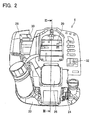
FIG 2 is a view showing a rear portion of a power unit of the mower. -
FIG. 3 is a sectional view taken along a line III-III inFig. 2 , and is a view showing an inner structure of the power unit. -
FIG. 4 is a block diagram showing an electric configuration of the mower of the embodiment. - In one embodiment of the present teachings, it is preferable that an engine includes an output shaft (for example, crankshaft) connected to a tool and an electric motor is configured to apply torque to the output shaft of the engine. According to the configuration, not only a human-carried work machine can simply be designed, but also loss of the torque outputted by the electric motor can be reduced.
- In one embodiment of the present teachings, it is preferable that the electric motor is fixed to the output shaft of the engine and includes a rotor that is provided with at least one magnet. In this case, it is further preferable that the rotor is provided with a cooling fan that is configured to send cooling air to the engine.
- In one embodiment of the present teachings, it is preferable that the electric motor includes a stator core that is fixed to a case (including a crankcase or a cylinder block) of the engine and faces the magnet of the rotor. In this case, it is preferable that the rotor includes a peripheral wall that surrounds the stator core, and the magnet is disposed on an inner surface of the peripheral wall.
- In one embodiment of the present teachings, it is preferable that the electric motor is configured to further function as an electric generator. According to the configuration, when there is an allowance in an output of the engine, electric energy can be stored. Alternatively, an increase in an energy efficiency and a reduction in a carbon dioxide emission amount can be achieved by performing regenerative braking for the tool.
- In the embodiment described above, it is preferable that the human-carried work machine further includes an operable portion that is configured to be operated by a user to adjust the output of the engine. In addition, it is preferable that when an amount of operation applied to the operable portion is less than a first predetermined amount, the electric motor is configured to serve as the electric generator, and when the amount of operation applied to the operable portion is more than a second predetermined amount, the electric motor is configured to serve as the prime mover for driving the tool.
- In one embodiment of the present teachings, it is preferable that the electric motor is configured to function as a "cell" motor (starter motor) for starting the engine. That is, it is preferable that the electric motor rotates the engine by applying the torque to the crankshaft when the user starts the engine (that is, when the user operates a starter switch). According to the configuration, the user can easily start the engine.
- In one embodiment of the present teachings, the human-carried work machine may be any of a mower, a weeder, a chain saw, a circular cutter (cut-off saw), a sprayer, a duster, a blower, or a dust collector. In this case, the tools of the human-carried work machine include not only cutters of a moving blade, a saw chain and the like but a blowing fan and a pump. Incidentally, the human-carried work machines are not limited to the examples described above but widely include work machines which the user carries to perform operations.
- In one embodiment of the present teachings, the engine for driving the tool may be either of a two stroke engine or a four stroke engine. Or, the engine may be an engine of other style (typically, internal combustion engine). The style of the engine is not particularly limited.
- In one embodiment of the present teachings, the electric motor for driving the tool may be either of a motor with a brush or a brushless motor. Or, the electric motor may be an electric motor of other style (typically, direct current motor). The style of the electric motor is not particularly limited. However, in a human-carried work machine which utilizes a combustible fuel, it is preferable to adopt a brushless motor which does not need a contact type commutator.
- In one embodiment of the present teachings, it is preferable that the human-carried work machine includes an electric power storage and electric power stored to the electric power storage is supplied to the electric motor. In addition, it is also preferable that in the human-carried work machine the electric power generated by the electric motor is supplied to the electric power storage to store. As one example, the electric power storage can adopt a battery pack that incorporates multiple secondary battery cells. In this case, it is further preferable that the secondary battery cell is a lithium ion cell.
- In the embodiment described above, a battery pack developed for an electric power tool can be preferably employed. The battery pack developed for the electric power tool, particularly, the battery pack that includes the lithium ion cell has a large capacity, and can discharge a large current. Consequently, the engine can sufficiently be assisted by the motor and the electric power that is generated by the motor can be stored by a large amount by adopting such a battery pack. Consequently, it is preferable that the human-carried work machine includes a battery attaching portion that attachably and detachably receives the battery pack (for example, a battery pack of a slidingly attachable and detachable type) that is developed for the electric power tool.
- In one embodiment of the teachings, it is preferable that the human-carried work machine performs idling stop. That is, it is preferable to automatically stop and start the engine in accordance with an operation of a throttle lever or a lock-off release switch by the user.
-
FIG. 1 shows an external appearance of amower 2 of an embodiment. Themower 2 is an example of a human-carried work machine. Themower 2 is provided with anoperation rod 4, apower unit 6 attached to a rear end portion of theoperation rod 4, agear head 8 attached to a front end portion of theoperation rod 4, amowing blade 10 in a circular disk shape attached to thegear head 8, asafety cover 12 attached to the front end portion of theoperation rod 4 to cover themowing blade 10, and ahandle 14 attached to a middle portion of theoperation rod 4. - The
operation rod 4 is formed in a hollow pipe shape, and extended linearly. A drive shaft (not illustrated) is contained at inside of theoperation rod 4. Torque outputted from thepower unit 6 is transmitted to thegear head 8 via the drive shaft at inside of theoperation rod 4 to rotate themowing blade 10. Thehandle 14 is provided with athrottle lever 16 which performs a throttle operation of anengine 20 described later, and a stop switch (not illustrated) for stopping theengine 20. Thethrottle lever 16 is an operable portion operated by a user for adjusting an output of the engine. - As shown in
FIG 2 andFIG 3 , thepower unit 6 is provided with theengine 20, afuel tank 22 for storing fuel of theengine 20, arecoil starter 26 for starting theengine 20, anair cleaner 28 for filtering air supplied to theengine 20, acarburetor 30 for mixing fuel to the supplied air, and amuffler 32 for discharging exhaust gas from theengine 20 to the atmosphere. Thecarburetor 30 is connected to thethrottle lever 16, and a throttle position of thecarburetor 30 is changed in accordance with an operation of thethrottle lever 16. - The
engine 20 is a four stroke engine of a separate oiling system. Theengine 20 is provided with acylinder 34, apiston 38 accommodated in thecylinder 34, anignition plug 36 provided at thecylinder 34, acrankcase 40, acrankshaft 42 accommodated in thecrankcase 40, and anoil pan 24. Thecrankshaft 42 is an output shaft of theengine 20, and connected to the drive shaft via a centrifugal clutch (not illustrated). Thereby, the output of theengine 20 is transmitted to themowing blade 10 through the drive shaft. That is, theengine 20 is a prime mover for driving themowing blade 10. - As shown in
FIG. 3 , thepower unit 6 is further provided with amotor 50. Themotor 50 is a brushless three phase motor of an outer rotor type. Themotor 50 is provided withstator cores 52, stator coils 54, anouter rotor 58, andmagnets 56. Thestator core 52 is formed by a magnetic material, and is fixed to thecrankcase 40. Thestator coil 54 is wound around thestator core 52 and excites thestator core 52 when electricity is conducted. Theouter rotor 58 is fixed to thecrankshaft 42, and is rotated along with thecrankshaft 42. Theouter rotor 58 is formed in a cup-like shape having a peripheral wall in a circular cylinder shape and a bottom wall provided to one end of the peripheral wall, and the peripheral wall surrounds thestator core 52. Themagnets 56 are fixed to an inner peripheral face of theouter rotor 58, and face thestator cores 52 disposed inside theouter rotor 58. - An output of the
motor 50 is applied from theouter rotor 58 to thecrankshaft 42 of theengine 20, and is transmitted to themowing blade 10 through the drive shaft. That is, themotor 50 is a second prime mover for driving themowing blade 10. As described above, themower 2 of the embodiment is a human-carried work machine of a hybrid type having different kinds of the prime movers of theengine 20 and themotor 50. For example, theengine 20 of the embodiment is an engine having the displacement of 25 cc (25 milliliters), and has an output of about 700 watts. On the other hand, themotor 50 has an output of about 650 watts. Consequently, a combination of theengine 20 and themotor 50 has an output of about 1350 watts, and the value corresponds to a 4 stroke engine having the displacement of 45 cc (45 milliliters). Thus, an output equivalent to that of an engine having a large displacement can be realized by combining theengine 20 and themotor 50, while using theengine 20 having a small displacement. - In addition, the
motor 50 can function also as a generator for converting rotational energy of thecrankshaft 42 to electric energy. For example, when there is an allowance in the output of theengine 20, a portion of the output of theengine 20 is converted into electric power by themotor 50. The electric power generated by themotor 50 is stored to abattery pack 90 described later. - Moreover, the
motor 50 can function as a "cell" motor (starter motor) for starting theengine 20. When the user operates a start switch (not illustrated), electric power is supplied from thebattery pack 90 to themotor 50, and themotor 50 rotates thecrankshaft 42. Thereby, theengine 20 is started. - The
outer rotor 58 of themotor 50 is integrally provided with a coolingfan 60. The coolingfan 60 is provided at an outer peripheral face of the peripheral wall of theouter rotor 58. The coolingfan 60 is configured to fan theengine 20, themotor 50, and acontroller unit 70 to cool. Incidentally, a position of arranging themotor 50 is a position at which a cooling fan is arranged in a conventional product. An enlargement of a size from that of the conventional product and a change in design are restrained by integrally forming the coolingfan 60 and theouter rotor 58. -
FIG 4 is a block diagram showing an electric configuration of thepower unit 6. As shown inFIG 4 , thepower unit 6 is provided with thecontroller unit 70, and thebattery pack 90 connected to thecontroller unit 70. Thecontroller unit 70 is configured by multiple integrated circuits including a microcomputer. Thecontroller unit 70 is a control portion for controlling operations of theengine 20 and themotor 50. Thebattery pack 90 contains multiple secondary battery cells, and supplies electric power to themotor 50 and theignition plug 36 via thecontroller unit 70. Thebattery pack 90 of the embodiment is a battery pack containing a lithium ion cell, and having a nominal voltage of 18 volts. - The
controller unit 70 is functionally provided with anengine igniter circuit 72, an ignitiontiming detector circuit 74, a throttleposition detector circuit 76, a rotorposition detector circuit 78, and amotor driver circuit 80. Theengine igniter circuit 72 supplies the electric power from thebattery pack 90 to theignition plug 36. At this time, the electric power from thebattery pack 90 is boosted in voltage by theignition coil 64. An electric discharge is produced by theignition plug 36 and an ignition to an air fuel mixture is carried out. The ignitiontiming detector circuit 74 determines ignition timing of theignition plug 36 while detecting a rotational position of thecrankshaft 42. The determined ignition timing is taught to theengine igniter circuit 72. The throttleposition detector circuit 76 is connected to thecarburetor 30, and detects a throttle position of thecarburetor 30. Incidentally, the throttleposition detector circuit 76 may detect an operation amount of thethrottle lever 16 by the user in place of the throttle position of thecarburetor 30. - The rotor
position detector circuit 78 is connected to anencoder 66 of themotor 50, and detects a rotational position of theouter rotor 58. Themotor driver circuit 80 is provided with multiple plural switching elements, and selectively connects respective phases of the stator coils 54 and respective electrodes of thebattery pack 90 in accordance with the detected rotational position of theouter rotor 58. Moreover, themotor driver circuit 80 can perform a PWM control of themotor 50 and can control the output of themotor 50 in accordance with the detected throttle position of thecarburetor 30. Also, themotor driver circuit 80 can make themotor 50 function as the generator by changing switching modes of the multiple switching elements. Thereby, thebattery pack 90 can be charged. That is, themotor driver circuit 80 functions also as the battery charge circuit. - In a case where an amount of a growth of weeds to be mown is a small amount (thin), the user operates the
throttle lever 16 by a small amount. In this case, the throttle position of thecarburetor 30 is also small, and there is an allowance in the output of theengine 20. Consequently, thecontroller unit 70 makes themotor 50 function as the generator and charges thebattery pack 90 by the output of theengine 20. - In a case where the amount of the growth of weeds to be mown is a middle amount, the user operates the
throttle lever 16 to a middle degree. In this case, also the throttle position of thecarburetor 30 is to a middle degree, and there is no excess and deficiency in the output of theengine 20. Consequently, thecontroller unit 70 does not make themotor 50 function also as the generator and does not make themotor 50 function also as the prime mover. - In a case where the amount of the growth of weeds to be mown is a large amount (thick), the user operates the
throttle lever 16 by a large amount. In this case, the throttle position of thecarburetor 30 is maximized, and the output of theengine 20 may be deficient. Consequently, thecontroller unit 70 makes themotor 50 function as the prime mover, and assists a deficient output of theengine 20 by themotor 50. A large amount of the growth of weeds can strongly be mown by driving themowing blade 10 by both of theengine 20 and themotor 50. - In a case where although the
throttle lever 16 is operated by a large amount, the amount of the growth of weeds to be mown is a small amount, or in a state of idling in which the mowing is not performed, a rotational frequency of the engine may be more than a predetermined value (for example, rotational frequency achieving maximum output), and at this time, it can be said that there is the allowance in the output of the engine. Consequently, when the rotational frequency of the engine is more than the predetermined value (particularly, the rotational frequency achieving the maximum output), it is preferable that thecontroller unit 70 makes themotor 50 function as the generator and charges thebattery pack 90 by the output of theengine 20. - When the user pulls back the
throttle lever 16 to an original point position, thecontroller unit 70 stops feeding electricity to theignition plug 36 and stops theengine 20. This is so-called idling stop. Thereafter, when the user operates thethrottle lever 16, thecontroller unit 70 drives thecrankshaft 42 by themotor 50 and restarts theengine 20. An energy consumption amount and an exhaust gas emission amount are reduced by avoiding useless idling. - Specific embodiment of the present teachings is described above, but this merely illustrates some possibilities of the teachings and do not restrict the claims thereof. The art set forth in the claims includes variations and modifications of the specific example set forth above. The technical elements disclosed in the specification or the drawings may be utilized separately or in all types of combinations, and are not limited to the combinations set forth in the claims at the time of filing of the application. Furthermore, the art disclosed herein may be utilized to simultaneously achieve a plurality of aims or to achieve one of these aims.
Claims (12)
- A human-carried work machine comprising an engine and an electric motor as a prime mover for driving a tool.
- The human-carried work machine as in claim 1, wherein
the engine comprises an output shaft that is connected to the tool, and
the electric motor is configured to apply torque to the output shaft of the engine. - The human-carried work machine as in claim 2, wherein the electric motor comprises a rotor that is fixed to the output shaft of the engine and is provided with at least one magnet.
- The human-carried work machine as in claim 3, wherein the rotor is provided with a cooling fan that is configured to send cooling air to the engine.
- The human-carried work machine as in claim 3 or 4, wherein the electric motor comprises a stator core that is fixed to a crankcase of the engine and faces the magnet of the rotor.
- The human-carried work machine as in claim 5, wherein the rotor comprises a peripheral wall that surrounds the stator core and the magnet is disposed on an inner surface of the peripheral wall.
- The human-carried work machine as in any one of claims 1 to 6, wherein the electric motor is configured to further function as an electric generator.
- The human-carried work machine as in claim 7, further comprising a battery that is configured to supply electric power to the electric motor, wherein electric power generated by the electric motor is stored in the battery.
- The human-carried work machine as in claim 7 or 8, further comprising an operable portion that is configured to be operated by a user to adjust output of the engine,
wherein the electric motor is configured to serve as the electric generator when an amount of operation applied to the operable portion is less than a first predetermined amount, and to serve as the prime mover for driving the tool when the amount of operation applied to the operable portion is more than a second predetermined amount. - The human-carried work machine as in claim 7 or 8, wherein the electric motor is configured to serve as the electric generator when a rotational frequency of the engine is equal to or more than a predetermined value.
- The human-carried work machine as in any one of claims 1 to 10, wherein the electric motor is configured to function as a starter motor for starting the engine.
- The human-carried work machine as in any one of claims 1 to 11, wherein the electric motor is a brushless motor.
Applications Claiming Priority (2)
| Application Number | Priority Date | Filing Date | Title |
|---|---|---|---|
| JP2011080892 | 2011-03-31 | ||
| PCT/JP2012/052934 WO2012132564A1 (en) | 2011-03-31 | 2012-02-09 | Mobile operating machine having hybrid driving system |
Publications (3)
| Publication Number | Publication Date |
|---|---|
| EP2693019A1 true EP2693019A1 (en) | 2014-02-05 |
| EP2693019A4 EP2693019A4 (en) | 2016-06-22 |
| EP2693019B1 EP2693019B1 (en) | 2017-04-05 |
Family
ID=46930329
Family Applications (1)
| Application Number | Title | Priority Date | Filing Date |
|---|---|---|---|
| EP12764283.3A Active EP2693019B1 (en) | 2011-03-31 | 2012-02-09 | Mobile operating machine having hybrid driving system |
Country Status (5)
| Country | Link |
|---|---|
| US (1) | US20140008092A1 (en) |
| EP (1) | EP2693019B1 (en) |
| JP (1) | JP5607820B2 (en) |
| CN (1) | CN103443418B (en) |
| WO (1) | WO2012132564A1 (en) |
Cited By (4)
| Publication number | Priority date | Publication date | Assignee | Title |
|---|---|---|---|---|
| EP2743036A3 (en) * | 2012-12-14 | 2014-06-25 | Makita Corporation | Power tool |
| EP2716411A3 (en) * | 2012-10-05 | 2014-06-25 | Makita Corporation | Power tool |
| EP2716410A3 (en) * | 2012-10-05 | 2014-08-20 | Makita Corporation | Power tool |
| EP3666482A4 (en) * | 2017-08-18 | 2020-08-05 | Nanjing Chervon Industry Co., Ltd. | CIRCULAR SAW |
Families Citing this family (22)
| Publication number | Priority date | Publication date | Assignee | Title |
|---|---|---|---|---|
| US8733072B2 (en) | 2011-11-04 | 2014-05-27 | Briggs & Stratton Corporation | Starter system for an engine |
| JP2014065114A (en) * | 2012-09-26 | 2014-04-17 | Makita Corp | Power tool |
| WO2014054380A1 (en) * | 2012-10-04 | 2014-04-10 | 株式会社マキタ | Charger having power generator |
| JP2014073567A (en) * | 2012-10-05 | 2014-04-24 | Makita Corp | Power tool |
| US10821591B2 (en) | 2012-11-13 | 2020-11-03 | Milwaukee Electric Tool Corporation | High-power cordless, hand-held power tool including a brushless direct current motor |
| WO2014126017A1 (en) * | 2013-02-12 | 2014-08-21 | 株式会社マキタ | Powered tool |
| JP2014173461A (en) * | 2013-03-07 | 2014-09-22 | Fuji Heavy Ind Ltd | Engine cooling device |
| JP6092006B2 (en) * | 2013-06-03 | 2017-03-08 | 株式会社クボタ | Mower |
| RU2616717C1 (en) * | 2013-06-20 | 2017-04-18 | Бриггз Энд Страттон Корпорэйшн | Internal combustion engine comprising electric starting system powered by lithium-ion battery |
| US11770048B2 (en) | 2013-10-18 | 2023-09-26 | Black & Decker, Inc. | Handheld power tool with a brushless electric motor |
| US9845782B1 (en) * | 2014-05-29 | 2017-12-19 | Bombardier Recreational Products Inc. | Method and system for starting an internal combustion engine |
| CN107002557A (en) * | 2014-10-23 | 2017-08-01 | 布里格斯和斯特拉顿公司 | Including the explosive motor by the battery-powered electric activation system of lithium-ion electric |
| WO2016150518A1 (en) * | 2015-03-26 | 2016-09-29 | Husqvarna Ab | Visible motor saw head layout |
| CN105508117A (en) * | 2016-01-15 | 2016-04-20 | 苏州科瓴精密机械科技有限公司 | Portable gasoline tool and electronic ignition system thereof |
| CN105545562A (en) * | 2016-01-15 | 2016-05-04 | 苏州科瓴精密机械科技有限公司 | Small gasoline engine |
| CN106194539B (en) * | 2016-07-25 | 2019-04-26 | 潍柴动力股份有限公司 | a power plant |
| JP6778575B2 (en) * | 2016-10-05 | 2020-11-04 | 株式会社マキタ | Work machine |
| US10814468B2 (en) | 2017-10-20 | 2020-10-27 | Milwaukee Electric Tool Corporation | Percussion tool |
| EP3701788B1 (en) * | 2017-10-24 | 2023-05-10 | Suzhou Cleva Precision Machinery & Technology Co., Ltd. | Gardening tool |
| CN214723936U (en) | 2018-01-26 | 2021-11-16 | 米沃奇电动工具公司 | Impact tool |
| CN110753603B (en) * | 2018-03-28 | 2022-09-16 | 南京泉峰科技有限公司 | Electric tool and control method thereof |
| US11973374B2 (en) | 2019-04-24 | 2024-04-30 | Black & Decker Inc. | Outer rotor brushless motor having an axial fan |
Family Cites Families (30)
| Publication number | Priority date | Publication date | Assignee | Title |
|---|---|---|---|---|
| US3497706A (en) * | 1966-02-25 | 1970-02-24 | Mcculloch Corp | Electrical starter system for gasoline engines |
| JPH05302526A (en) * | 1992-04-24 | 1993-11-16 | Nippondenso Co Ltd | Device for restraining variation in engine speed |
| JP3176765B2 (en) * | 1993-06-17 | 2001-06-18 | 本田技研工業株式会社 | Hybrid power supply for electric traveling vehicles |
| DE4404791C1 (en) * | 1994-02-08 | 1995-03-30 | Mannesmann Ag | Structural unit comprising an internal combustion engine and an electrical generator |
| US5794422A (en) * | 1995-11-13 | 1998-08-18 | Ransomes America Corporation | Electric drive mower with motor generator set |
| WO1997028681A2 (en) * | 1996-02-09 | 1997-08-14 | The Toro Company | Electric drive riding mower |
| US6622683B2 (en) * | 1998-10-30 | 2003-09-23 | Briggs & Stratton Corporation | Engine starting and stopping device |
| US6595176B2 (en) * | 1998-10-30 | 2003-07-22 | Briggs & Stratton Corporation | Engine starting and stopping device |
| US6230678B1 (en) * | 1998-10-30 | 2001-05-15 | Briggs & Stratton Corporation | Starting and stopping device for internal combustion engine |
| SE520988C2 (en) * | 1998-11-12 | 2003-09-16 | Stihl Maschf Andreas | Hand-made work tool with generator |
| JP2001173024A (en) * | 1999-12-17 | 2001-06-26 | Shin Caterpillar Mitsubishi Ltd | Hybrid system for construction machine |
| JP2002089417A (en) * | 2000-09-13 | 2002-03-27 | Unisia Jecs Corp | Engine starter |
| JP3711853B2 (en) * | 2000-09-14 | 2005-11-02 | いすゞ自動車株式会社 | Hybrid drive device |
| JP2004092634A (en) * | 2002-07-12 | 2004-03-25 | Kokusan Denki Co Ltd | Internal combustion engine drive vehicle with on-vehicle generator |
| WO2004057166A2 (en) * | 2002-11-22 | 2004-07-08 | Honda Motor Company, Ltd. | Hybrid power equipment |
| US7292009B2 (en) * | 2003-09-17 | 2007-11-06 | Honda Motor Co., Ltd. | Hybrid type working machine |
| CN1286687C (en) * | 2003-12-31 | 2006-11-29 | 上汽集团奇瑞汽车有限公司 | Mixed power car control system |
| US7024859B2 (en) * | 2004-02-02 | 2006-04-11 | Illinois Institute Of Technology | Combustion engine acceleration support using an integrated starter/alternator |
| JP4219848B2 (en) * | 2004-04-09 | 2009-02-04 | 本田技研工業株式会社 | Underwater scooter |
| US20060123635A1 (en) * | 2004-12-09 | 2006-06-15 | Heow, Inc. | Combination blower, trimmer and edger for tending vegetation |
| JP2006314278A (en) * | 2005-05-13 | 2006-11-24 | Fuji Heavy Ind Ltd | Brush cutter |
| US7480998B2 (en) * | 2005-05-09 | 2009-01-27 | Fuji Jukogyo Kabushiki Kaisha | Bush cutter |
| US7467697B2 (en) * | 2005-10-07 | 2008-12-23 | Ford Global Technologies, Llc | Electromagnetic coupling device for engine accessories |
| CN1319770C (en) * | 2005-10-15 | 2007-06-06 | 谢百年 | Parallet type mixed power electric motor for automobile |
| US20070277793A1 (en) * | 2006-06-01 | 2007-12-06 | Edward Lawrence Warren | Method for operating an internal combustion engine |
| JP2009036183A (en) * | 2007-08-03 | 2009-02-19 | Nissan Motor Co Ltd | Engine exhaust purification control apparatus and hybrid vehicle exhaust purification control apparatus using the same |
| JP2009041668A (en) * | 2007-08-09 | 2009-02-26 | Yamaha Motor Co Ltd | Power unit and straddle-type vehicle |
| GB2461536A (en) * | 2008-07-01 | 2010-01-06 | Parvaiz Akhtar | Block paving cleaner |
| JP5201410B2 (en) | 2008-09-30 | 2013-06-05 | 日立工機株式会社 | Engine tools |
| JP2014073566A (en) * | 2012-10-05 | 2014-04-24 | Makita Corp | Power tool |
-
2012
- 2012-02-09 WO PCT/JP2012/052934 patent/WO2012132564A1/en not_active Ceased
- 2012-02-09 JP JP2013507235A patent/JP5607820B2/en active Active
- 2012-02-09 EP EP12764283.3A patent/EP2693019B1/en active Active
- 2012-02-09 CN CN201280013789.3A patent/CN103443418B/en active Active
- 2012-02-09 US US14/007,049 patent/US20140008092A1/en not_active Abandoned
Cited By (4)
| Publication number | Priority date | Publication date | Assignee | Title |
|---|---|---|---|---|
| EP2716411A3 (en) * | 2012-10-05 | 2014-06-25 | Makita Corporation | Power tool |
| EP2716410A3 (en) * | 2012-10-05 | 2014-08-20 | Makita Corporation | Power tool |
| EP2743036A3 (en) * | 2012-12-14 | 2014-06-25 | Makita Corporation | Power tool |
| EP3666482A4 (en) * | 2017-08-18 | 2020-08-05 | Nanjing Chervon Industry Co., Ltd. | CIRCULAR SAW |
Also Published As
| Publication number | Publication date |
|---|---|
| US20140008092A1 (en) | 2014-01-09 |
| CN103443418B (en) | 2018-09-07 |
| EP2693019A4 (en) | 2016-06-22 |
| WO2012132564A1 (en) | 2012-10-04 |
| JPWO2012132564A1 (en) | 2014-07-24 |
| JP5607820B2 (en) | 2014-10-15 |
| EP2693019B1 (en) | 2017-04-05 |
| CN103443418A (en) | 2013-12-11 |
Similar Documents
| Publication | Publication Date | Title |
|---|---|---|
| EP2693019B1 (en) | Mobile operating machine having hybrid driving system | |
| JP5776139B2 (en) | Back working work machine and work machine | |
| JP2014073567A (en) | Power tool | |
| JP4114788B2 (en) | Hybrid working machine | |
| US20140083375A1 (en) | Power tool | |
| EP2743036A2 (en) | Power tool | |
| WO2021033410A1 (en) | Electric work machine | |
| KR101937602B1 (en) | Engine, self-starter unit, and method for altering engine specifications | |
| US20140084704A1 (en) | Power tool | |
| JP2014066198A (en) | Power tool | |
| WO2014002846A1 (en) | Hybrid system and portable work machine provided with same | |
| JP2014151415A (en) | Power tool | |
| JP2011251348A (en) | Engine cutter | |
| JP2014073568A (en) | Power tool | |
| JP2014079240A (en) | Power tool | |
| CN106787066B (en) | Magneto and hybrid power system for motorcycle | |
| JP2014151414A (en) | Power tool | |
| JP5789924B2 (en) | Engine for portable work machine and portable work machine equipped with the same | |
| JP2013151863A (en) | Engine working machine | |
| JP2014065113A (en) | Power tool | |
| JP2005102352A (en) | Power control device | |
| JP2026037776A (en) | electric work equipment | |
| JP2014065112A (en) | Power tool | |
| JP2014065111A (en) | Power tool | |
| TWM611621U (en) | Internal rotary electric lawn mower |
Legal Events
| Date | Code | Title | Description |
|---|---|---|---|
| PUAI | Public reference made under article 153(3) epc to a published international application that has entered the european phase |
Free format text: ORIGINAL CODE: 0009012 |
|
| 17P | Request for examination filed |
Effective date: 20130926 |
|
| AK | Designated contracting states |
Kind code of ref document: A1 Designated state(s): AL AT BE BG CH CY CZ DE DK EE ES FI FR GB GR HR HU IE IS IT LI LT LU LV MC MK MT NL NO PL PT RO RS SE SI SK SM TR |
|
| DAX | Request for extension of the european patent (deleted) | ||
| RA4 | Supplementary search report drawn up and despatched (corrected) |
Effective date: 20160524 |
|
| RIC1 | Information provided on ipc code assigned before grant |
Ipc: F02N 11/04 20060101ALI20160518BHEP Ipc: B25F 5/00 20060101ALI20160518BHEP Ipc: H02K 7/18 20060101ALI20160518BHEP Ipc: H02K 7/14 20060101ALI20160518BHEP Ipc: F02B 63/02 20060101AFI20160518BHEP |
|
| GRAP | Despatch of communication of intention to grant a patent |
Free format text: ORIGINAL CODE: EPIDOSNIGR1 |
|
| INTG | Intention to grant announced |
Effective date: 20161216 |
|
| GRAS | Grant fee paid |
Free format text: ORIGINAL CODE: EPIDOSNIGR3 |
|
| GRAA | (expected) grant |
Free format text: ORIGINAL CODE: 0009210 |
|
| AK | Designated contracting states |
Kind code of ref document: B1 Designated state(s): AL AT BE BG CH CY CZ DE DK EE ES FI FR GB GR HR HU IE IS IT LI LT LU LV MC MK MT NL NO PL PT RO RS SE SI SK SM TR |
|
| REG | Reference to a national code |
Ref country code: GB Ref legal event code: FG4D |
|
| REG | Reference to a national code |
Ref country code: CH Ref legal event code: EP |
|
| REG | Reference to a national code |
Ref country code: AT Ref legal event code: REF Ref document number: 882073 Country of ref document: AT Kind code of ref document: T Effective date: 20170415 |
|
| REG | Reference to a national code |
Ref country code: IE Ref legal event code: FG4D |
|
| REG | Reference to a national code |
Ref country code: DE Ref legal event code: R096 Ref document number: 602012030793 Country of ref document: DE |
|
| REG | Reference to a national code |
Ref country code: NL Ref legal event code: MP Effective date: 20170405 |
|
| REG | Reference to a national code |
Ref country code: LT Ref legal event code: MG4D |
|
| REG | Reference to a national code |
Ref country code: AT Ref legal event code: MK05 Ref document number: 882073 Country of ref document: AT Kind code of ref document: T Effective date: 20170405 |
|
| PG25 | Lapsed in a contracting state [announced via postgrant information from national office to epo] |
Ref country code: NL Free format text: LAPSE BECAUSE OF FAILURE TO SUBMIT A TRANSLATION OF THE DESCRIPTION OR TO PAY THE FEE WITHIN THE PRESCRIBED TIME-LIMIT Effective date: 20170405 |
|
| PG25 | Lapsed in a contracting state [announced via postgrant information from national office to epo] |
Ref country code: HR Free format text: LAPSE BECAUSE OF FAILURE TO SUBMIT A TRANSLATION OF THE DESCRIPTION OR TO PAY THE FEE WITHIN THE PRESCRIBED TIME-LIMIT Effective date: 20170405 Ref country code: AT Free format text: LAPSE BECAUSE OF FAILURE TO SUBMIT A TRANSLATION OF THE DESCRIPTION OR TO PAY THE FEE WITHIN THE PRESCRIBED TIME-LIMIT Effective date: 20170405 Ref country code: ES Free format text: LAPSE BECAUSE OF FAILURE TO SUBMIT A TRANSLATION OF THE DESCRIPTION OR TO PAY THE FEE WITHIN THE PRESCRIBED TIME-LIMIT Effective date: 20170405 Ref country code: GR Free format text: LAPSE BECAUSE OF FAILURE TO SUBMIT A TRANSLATION OF THE DESCRIPTION OR TO PAY THE FEE WITHIN THE PRESCRIBED TIME-LIMIT Effective date: 20170706 Ref country code: FI Free format text: LAPSE BECAUSE OF FAILURE TO SUBMIT A TRANSLATION OF THE DESCRIPTION OR TO PAY THE FEE WITHIN THE PRESCRIBED TIME-LIMIT Effective date: 20170405 Ref country code: NO Free format text: LAPSE BECAUSE OF FAILURE TO SUBMIT A TRANSLATION OF THE DESCRIPTION OR TO PAY THE FEE WITHIN THE PRESCRIBED TIME-LIMIT Effective date: 20170705 Ref country code: LT Free format text: LAPSE BECAUSE OF FAILURE TO SUBMIT A TRANSLATION OF THE DESCRIPTION OR TO PAY THE FEE WITHIN THE PRESCRIBED TIME-LIMIT Effective date: 20170405 |
|
| PG25 | Lapsed in a contracting state [announced via postgrant information from national office to epo] |
Ref country code: PL Free format text: LAPSE BECAUSE OF FAILURE TO SUBMIT A TRANSLATION OF THE DESCRIPTION OR TO PAY THE FEE WITHIN THE PRESCRIBED TIME-LIMIT Effective date: 20170405 Ref country code: LV Free format text: LAPSE BECAUSE OF FAILURE TO SUBMIT A TRANSLATION OF THE DESCRIPTION OR TO PAY THE FEE WITHIN THE PRESCRIBED TIME-LIMIT Effective date: 20170405 Ref country code: SE Free format text: LAPSE BECAUSE OF FAILURE TO SUBMIT A TRANSLATION OF THE DESCRIPTION OR TO PAY THE FEE WITHIN THE PRESCRIBED TIME-LIMIT Effective date: 20170405 Ref country code: RS Free format text: LAPSE BECAUSE OF FAILURE TO SUBMIT A TRANSLATION OF THE DESCRIPTION OR TO PAY THE FEE WITHIN THE PRESCRIBED TIME-LIMIT Effective date: 20170405 Ref country code: IS Free format text: LAPSE BECAUSE OF FAILURE TO SUBMIT A TRANSLATION OF THE DESCRIPTION OR TO PAY THE FEE WITHIN THE PRESCRIBED TIME-LIMIT Effective date: 20170805 Ref country code: BG Free format text: LAPSE BECAUSE OF FAILURE TO SUBMIT A TRANSLATION OF THE DESCRIPTION OR TO PAY THE FEE WITHIN THE PRESCRIBED TIME-LIMIT Effective date: 20170705 |
|
| REG | Reference to a national code |
Ref country code: DE Ref legal event code: R097 Ref document number: 602012030793 Country of ref document: DE |
|
| PG25 | Lapsed in a contracting state [announced via postgrant information from national office to epo] |
Ref country code: RO Free format text: LAPSE BECAUSE OF FAILURE TO SUBMIT A TRANSLATION OF THE DESCRIPTION OR TO PAY THE FEE WITHIN THE PRESCRIBED TIME-LIMIT Effective date: 20170405 Ref country code: DK Free format text: LAPSE BECAUSE OF FAILURE TO SUBMIT A TRANSLATION OF THE DESCRIPTION OR TO PAY THE FEE WITHIN THE PRESCRIBED TIME-LIMIT Effective date: 20170405 Ref country code: CZ Free format text: LAPSE BECAUSE OF FAILURE TO SUBMIT A TRANSLATION OF THE DESCRIPTION OR TO PAY THE FEE WITHIN THE PRESCRIBED TIME-LIMIT Effective date: 20170405 Ref country code: EE Free format text: LAPSE BECAUSE OF FAILURE TO SUBMIT A TRANSLATION OF THE DESCRIPTION OR TO PAY THE FEE WITHIN THE PRESCRIBED TIME-LIMIT Effective date: 20170405 Ref country code: SK Free format text: LAPSE BECAUSE OF FAILURE TO SUBMIT A TRANSLATION OF THE DESCRIPTION OR TO PAY THE FEE WITHIN THE PRESCRIBED TIME-LIMIT Effective date: 20170405 |
|
| PLBE | No opposition filed within time limit |
Free format text: ORIGINAL CODE: 0009261 |
|
| STAA | Information on the status of an ep patent application or granted ep patent |
Free format text: STATUS: NO OPPOSITION FILED WITHIN TIME LIMIT |
|
| PG25 | Lapsed in a contracting state [announced via postgrant information from national office to epo] |
Ref country code: IT Free format text: LAPSE BECAUSE OF FAILURE TO SUBMIT A TRANSLATION OF THE DESCRIPTION OR TO PAY THE FEE WITHIN THE PRESCRIBED TIME-LIMIT Effective date: 20170405 Ref country code: SM Free format text: LAPSE BECAUSE OF FAILURE TO SUBMIT A TRANSLATION OF THE DESCRIPTION OR TO PAY THE FEE WITHIN THE PRESCRIBED TIME-LIMIT Effective date: 20170405 |
|
| 26N | No opposition filed |
Effective date: 20180108 |
|
| PG25 | Lapsed in a contracting state [announced via postgrant information from national office to epo] |
Ref country code: SI Free format text: LAPSE BECAUSE OF FAILURE TO SUBMIT A TRANSLATION OF THE DESCRIPTION OR TO PAY THE FEE WITHIN THE PRESCRIBED TIME-LIMIT Effective date: 20170405 |
|
| REG | Reference to a national code |
Ref country code: CH Ref legal event code: PL |
|
| PG25 | Lapsed in a contracting state [announced via postgrant information from national office to epo] |
Ref country code: MC Free format text: LAPSE BECAUSE OF FAILURE TO SUBMIT A TRANSLATION OF THE DESCRIPTION OR TO PAY THE FEE WITHIN THE PRESCRIBED TIME-LIMIT Effective date: 20170405 |
|
| GBPC | Gb: european patent ceased through non-payment of renewal fee |
Effective date: 20180209 |
|
| REG | Reference to a national code |
Ref country code: BE Ref legal event code: MM Effective date: 20180228 |
|
| PG25 | Lapsed in a contracting state [announced via postgrant information from national office to epo] |
Ref country code: LI Free format text: LAPSE BECAUSE OF NON-PAYMENT OF DUE FEES Effective date: 20180228 Ref country code: LU Free format text: LAPSE BECAUSE OF NON-PAYMENT OF DUE FEES Effective date: 20180209 Ref country code: CH Free format text: LAPSE BECAUSE OF NON-PAYMENT OF DUE FEES Effective date: 20180228 |
|
| REG | Reference to a national code |
Ref country code: FR Ref legal event code: ST Effective date: 20181031 |
|
| REG | Reference to a national code |
Ref country code: IE Ref legal event code: MM4A |
|
| PG25 | Lapsed in a contracting state [announced via postgrant information from national office to epo] |
Ref country code: IE Free format text: LAPSE BECAUSE OF NON-PAYMENT OF DUE FEES Effective date: 20180209 |
|
| PG25 | Lapsed in a contracting state [announced via postgrant information from national office to epo] |
Ref country code: GB Free format text: LAPSE BECAUSE OF NON-PAYMENT OF DUE FEES Effective date: 20180209 Ref country code: FR Free format text: LAPSE BECAUSE OF NON-PAYMENT OF DUE FEES Effective date: 20180228 Ref country code: BE Free format text: LAPSE BECAUSE OF NON-PAYMENT OF DUE FEES Effective date: 20180228 |
|
| PG25 | Lapsed in a contracting state [announced via postgrant information from national office to epo] |
Ref country code: MT Free format text: LAPSE BECAUSE OF NON-PAYMENT OF DUE FEES Effective date: 20180209 |
|
| PG25 | Lapsed in a contracting state [announced via postgrant information from national office to epo] |
Ref country code: TR Free format text: LAPSE BECAUSE OF FAILURE TO SUBMIT A TRANSLATION OF THE DESCRIPTION OR TO PAY THE FEE WITHIN THE PRESCRIBED TIME-LIMIT Effective date: 20170405 |
|
| PG25 | Lapsed in a contracting state [announced via postgrant information from national office to epo] |
Ref country code: HU Free format text: LAPSE BECAUSE OF FAILURE TO SUBMIT A TRANSLATION OF THE DESCRIPTION OR TO PAY THE FEE WITHIN THE PRESCRIBED TIME-LIMIT; INVALID AB INITIO Effective date: 20120209 Ref country code: PT Free format text: LAPSE BECAUSE OF FAILURE TO SUBMIT A TRANSLATION OF THE DESCRIPTION OR TO PAY THE FEE WITHIN THE PRESCRIBED TIME-LIMIT Effective date: 20170405 |
|
| PG25 | Lapsed in a contracting state [announced via postgrant information from national office to epo] |
Ref country code: CY Free format text: LAPSE BECAUSE OF FAILURE TO SUBMIT A TRANSLATION OF THE DESCRIPTION OR TO PAY THE FEE WITHIN THE PRESCRIBED TIME-LIMIT Effective date: 20170405 Ref country code: MK Free format text: LAPSE BECAUSE OF NON-PAYMENT OF DUE FEES Effective date: 20170405 |
|
| PG25 | Lapsed in a contracting state [announced via postgrant information from national office to epo] |
Ref country code: AL Free format text: LAPSE BECAUSE OF FAILURE TO SUBMIT A TRANSLATION OF THE DESCRIPTION OR TO PAY THE FEE WITHIN THE PRESCRIBED TIME-LIMIT Effective date: 20170405 |
|
| PGFP | Annual fee paid to national office [announced via postgrant information from national office to epo] |
Ref country code: DE Payment date: 20251230 Year of fee payment: 15 |