EP2743036A2 - Power tool - Google Patents
Power tool Download PDFInfo
- Publication number
- EP2743036A2 EP2743036A2 EP13005705.2A EP13005705A EP2743036A2 EP 2743036 A2 EP2743036 A2 EP 2743036A2 EP 13005705 A EP13005705 A EP 13005705A EP 2743036 A2 EP2743036 A2 EP 2743036A2
- Authority
- EP
- European Patent Office
- Prior art keywords
- engine
- operating member
- throttle
- power tool
- user
- Prior art date
- Legal status (The legal status is an assumption and is not a legal conclusion. Google has not performed a legal analysis and makes no representation as to the accuracy of the status listed.)
- Withdrawn
Links
Images


Classifications
-
- B—PERFORMING OPERATIONS; TRANSPORTING
- B25—HAND TOOLS; PORTABLE POWER-DRIVEN TOOLS; MANIPULATORS
- B25F—COMBINATION OR MULTI-PURPOSE TOOLS NOT OTHERWISE PROVIDED FOR; DETAILS OR COMPONENTS OF PORTABLE POWER-DRIVEN TOOLS NOT PARTICULARLY RELATED TO THE OPERATIONS PERFORMED AND NOT OTHERWISE PROVIDED FOR
- B25F5/00—Details or components of portable power-driven tools not particularly related to the operations performed and not otherwise provided for
-
- F—MECHANICAL ENGINEERING; LIGHTING; HEATING; WEAPONS; BLASTING
- F02—COMBUSTION ENGINES; HOT-GAS OR COMBUSTION-PRODUCT ENGINE PLANTS
- F02B—INTERNAL-COMBUSTION PISTON ENGINES; COMBUSTION ENGINES IN GENERAL
- F02B63/00—Adaptations of engines for driving pumps, hand-held tools or electric generators; Portable combinations of engines with engine-driven devices
- F02B63/02—Adaptations of engines for driving pumps, hand-held tools or electric generators; Portable combinations of engines with engine-driven devices for hand-held tools
-
- F—MECHANICAL ENGINEERING; LIGHTING; HEATING; WEAPONS; BLASTING
- F02—COMBUSTION ENGINES; HOT-GAS OR COMBUSTION-PRODUCT ENGINE PLANTS
- F02N—STARTING OF COMBUSTION ENGINES; STARTING AIDS FOR SUCH ENGINES, NOT OTHERWISE PROVIDED FOR
- F02N11/00—Starting of engines by means of electric motors
- F02N11/08—Circuits or control means specially adapted for starting of engines
- F02N11/0803—Circuits or control means specially adapted for starting of engines characterised by means for initiating engine start or stop
-
- F—MECHANICAL ENGINEERING; LIGHTING; HEATING; WEAPONS; BLASTING
- F02—COMBUSTION ENGINES; HOT-GAS OR COMBUSTION-PRODUCT ENGINE PLANTS
- F02N—STARTING OF COMBUSTION ENGINES; STARTING AIDS FOR SUCH ENGINES, NOT OTHERWISE PROVIDED FOR
- F02N11/00—Starting of engines by means of electric motors
- F02N11/10—Safety devices
- F02N11/101—Safety devices for preventing engine starter actuation or engagement
Definitions
- the invention relates to a power tool in which a tool bit is driven by an engine and performs a predetermined operation on a workpiece.
- Japanese laid-open Patent Publication No. 2011-244724 discloses a bush cutter in which a tool bit is driven using an engine as a driving source.
- engine driving output is used both for cutting operation and for charging a battery when being idled.
- a representative power tool which includes an engine for driving a tool bit, a starting member that is operated to start the engine, an operating member that is operated to adjust an output of the engine, and a controller that stops driving of the engine for an idling stop according to the operation of the operating member.
- the "power tool” in the invention typically and suitably includes a chain saw, a hedge trimmer, a power cutter or other similar handheld power tools.
- the "starting member” in the invention typically represents a start switch, but, if it is required to stop the engine, it may represent a start-stop switch which also serves as a stop switch.
- the manner of "adjusting an output of the engine” in the invention typically and suitably includes a manner of adjusting the magnitude of the output torque to be outputted to the output shaft of the engine, and a manner of adjusting the rotating speed of the output shaft of the engine.
- the "operating member” in the invention typically represents a throttle lever and an accelerator lever.
- driving of the engine is stopped according to the operation of the operating member which is operated to adjust the output of the engine.
- the operating member can be placed into an initial position in which the operating member is not operated yet and an operated position in which the operating member has been operated. Further, the controller stops driving of the engine when the operating member is returned from the operated position to the initial position.
- driving of the engine is stopped when the operating member is returned from the operated position to the initial position. In other words, driving of the engine is stopped when the output of the engine is not required.
- the controller stops driving of the engine after a lapse of a first predetermined time since the operating member has been returned from the operated position to the initial position.
- driving of the engine is stopped after a lapse of the first predetermined time since the operating member has been returned from the operated position to the initial position. In other words, driving of the engine is not stopped until the first predetermined time elapses.
- the controller restarts the engine without operating the starting member when the operating member is placed into the operated position again.
- the power tool further includes a switching member which is selectively placed in either one of an operation enabled position in which operation of the operating member from the initial position to the operated position is enabled and an operation disabled position in which operation of the operating member from the initial position to the operated position is disabled. Further, when the operating member is returned from the operated position to the initial position and the switching member is returned from the operation enabled position to the operation disabled position, the controller restarts the engine only by operation of the starting member.
- the engine when the operating member is returned from the operated position to the initial position and the switching member is returned from the operation enabled position to the operation disabled position, the engine is not restarted, or the power tool itself is stopped, unless the starting member is operated.
- the operating member cannot be switched from the initial position to the operated position, or the tool bit cannot be driven, until the switching member is switched from the operation disabled position to the operation enabled position.
- the tool bit can be prevented from being driven by user's unintentional operation of the operating member.
- the controller restarts the engine without operating the starting member.
- the engine is restarted without operating the starting member only when the operating member is placed into the operated position again within the second predetermined time after the return of the operating member to the initial position.
- the engine is not restarted unless the starting member is operated.
- the power tool further includes a housing that houses the engine, and a first handle to be held by a user. Further, the first handle protrudes from the housing, and the operating member and the switching member are provided on the first handle.
- both the operating member and the switching member are provided on the first handle.
- the operating member is provided in a region of the first handle which comes in contact with user's fingers
- the switching member is provided in a region of the first handle which comes in contact with user's palm.
- the user when the user holds the first handle, the user can operate the operating member with the palm of the hand holding the first handle, and at the same time, the user can also operate the switching member with the fingers of the same hand. Therefore, the operating member and the switching member are improved in operability.
- the power tool further includes a housing that houses the engine, and a first handle and a second handle to be held by a user. Further, the first and second handles protrude from the housing, and the operating member is provided on the first handle and the switching member is provided on the second handle.
- the operating member is provided on the first handle and the switching member is provided on the second handle.
- the user can operate the operating member with the hand holding the first handle and can operate the switching member with the other hand holding the second handle.
- the power tool further includes an informing member for informing the user that the power tool is ready to restart the engine by user's operation of the operating member from the initial position to the operated position.
- the power tool is ready to automatically restart the engine by user's operation of switching the operating member from the initial position to the operated position.
- the user can recognize this status of the engine.
- FIG. 1 is a configuration diagram schematically showing the configuration of a chain saw 100.
- the chain saw 100 mainly includes a body 101 which forms an outer shell of the chain saw 100, a guide bar 103 which protrudes horizontally from one side of the body 101, a front handle 106, a rear handle 107 and a hand guard 108 which are connected to the body 101, and a controller 139 which controls the entire chain saw 100.
- the chain saw 100 is designed as a cutting tool that performs a cutting operation on a workpiece by rotating a saw chain 105 mounted on a guide bar 103.
- the chain saw 100, the saw chain 105, the rear handle 107 and the controller 139 are features that correspond to the "power tool”, the “tool bit”, the “first handle” and the “controller”, respectively, according to the invention.
- the side of the protruding guide bar 103 (the left side as viewed in FIG. 1 ) is taken as the "front” or “front region” and its opposite side (the rear handle 107 side, the right side as viewed in FIG. 1 ) as the "rear” or "rear region”.
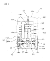
- FIG. 2 is a sectional view taken along line II-II of FIG. 1 .
- the body 101 mainly includes an engine 111 and an electric motor 141 which both serve to drive the saw chain 105, and a body housing 102 which houses the engine 111 and the electric motor 141. Therefore, the chain saw 100 according to this embodiment is configured as a hybrid power tool that is driven by both the engine 111 and the electric motor 141.
- the engine 111 and the body housing 102 are features that correspond to the "engine” and the "housing", respectively, according to the invention.
- the engine 111 is configured as a reciprocating engine which mainly includes a cylinder block 113, a piston 115, a spark plug 117, a crank case 119, a crank shaft 123 and a connecting rod 125.
- a single-cylinder, two-stroke small engine is used as the engine 111.
- the cylinder block 113 has a cylinder bore 113a in which the piston 115 can slide, and a combustion chamber 113b which is formed in a recessed shape at the upper end of the cylinder bore 113a.
- An internal-combustion chamber is defined by a region surrounded by the cylinder bore 113a, the combustion chamber 113b and the piston 115. The volume of the internal-combustion chamber is compressed and expanded by sliding of the piston 115 within the cylinder bore 113a.
- the spark plug 117 is provided on the combustion chamber 113b.
- the crank case 119 is provided below the cylinder block 113 and connected to the cylinder block 113.
- the crank shaft 123 is rotatably supported by the crank case 119 via a plurality of bearings 121.
- the crank shaft 123 is arranged such that its axis extends perpendicularly to the axial direction of the cylinder bore 113a (the vertical direction as viewed in FIG. 2 ) and to the extending direction of the guide bar 103 (the horizontal direction as viewed in FIG. 1 , a direction perpendicular to the plane of FIG. 2 ).
- the crank shaft 123 is connected to the piston 115 via the connecting rod 125.
- linear motion of the piston 115 is converted into rotation of the crank shaft 123.
- crank shaft 123 protrudes through one side of the crank case 119, and the electric motor 141 which is described below is mounted on this end.
- the other end (right end as viewed in FIG. 2 ) of the crank shaft 123 protrudes through the other side of the crank case 119, and a centrifugal clutch 127 is mounted on this end.
- the centrifugal clutch 127 is configured to cause a clutch shoe (not shown) to expand radially outward and get in contact with an inner circumferential surface of a clutch outer 127a by using centrifugal force which is developed by rotation of the crank shaft 123. With this construction, rotation of the clutch shaft 123 can be transmitted to the clutch outer 127a.
- a final output shaft 131 is fixedly mounted coaxially with the crank shaft 123 on the outer surface (on the right side as viewed in FIG. 2 , facing away from the crank case 119) of the clutch outer 127a and connected to the saw chain 105.
- the electric motor 141 is configured as an outer rotor motor having a stator core 143, a stator coil 145, an outer rotor 147 and a magnet 149.
- the electric motor 141 is capable of rotating in both forward and reverse directions and serves not only as a motor for assisting drive of the engine 111, but as a generator and a cell motor for starting the engine 111.
- the stator core 143 is a disc-like member formed of magnetic material and fixedly mounted to the outer surface of the crank case 119. As shown in FIG. 2 , the stator core 143 has a center hole in its center, and the crank shaft 123 is loosely fitted through the center hole.
- the stator coil 145 is wound on the stator core 143 and excites the stator core 143 when energized.
- the outer rotor 147 is a cup-like member having a cylindrical peripheral wall 147a and a bottom wall 147b, and the peripheral wall 147a surrounds the outer circumferential surface of the stator core 143.
- the magnet 149 is arranged on the inner circumferential surface of the peripheral wall 147a such that it faces the outer circumferential surface of the stator core 143.
- a cooling fan 148 is provided on the outer circumferential surface of the peripheral wall 147a.
- the crank shaft 123 is coaxially connected to the center of the bottom wall 147b, so that the crank shaft 123 also serves as a rotation axis of the electric motor 141.
- a motor control circuit 142 includes a plurality of switching elements (not shown).
- the controller 139 controls switching of the switching elements to start and stop supply of electric current to the electric motor 141. Thus, driving of the electric motor 141 is controlled.
- an LED 381 is provided on the body housing 102 at a position which can be visually recognized by the user during cutting operation on a workpiece.
- the LED 381 is a light-emitting diode which emits light by electric current supplied from a battery pack 337 which is described below.
- the LED 381 is a feature that corresponds to the "informing member" according to the invention.
- the rear handle 107 is connected to a lower region of a rear end of the body housing 102 and extends rearward, and has a shape of a generally triangular loop having an opening at the center in side view.
- the rear handle 107 has an upper part 107a and a lower part 107b, and the upper part 107a and the lower part 107b are connected to each other at their rear ends.
- the upper part 107a of the rear handle 107 is connected to a central part of the rear end of the body housing 102 and extends rearward and obliquely downward in a curved shape.
- the upper part 107a forms a grip to be held by a user.
- a throttle lever 135 is provided in a region of the upper part 107a facing the central opening (on the lower side as viewed in FIG. 1 ) which comes in contact with user's fingers, as shown in FIG. 1 .
- the amount of inflow of air-fuel mixture to be supplied to the engine 111 can be controlled by adjusting the depressing amount of the throttle lever 135.
- the throttle lever 135 is configured as an operating member for adjusting the magnitude of the output torque to be outputted to the crank shaft 123. Further, the throttle lever 135 also serves as an operating member for adjusting the magnitude of the output torque to be outputted from the electric motor 141 to the crank shaft 123.
- the throttle lever 135 is a feature that corresponds to the "operating member" according to the invention.
- a throttle lock lever 136 is provided in a region of the upper part 107a on the opposite side from the throttle lever 135 (on the side facing away from the central opening, on the upper side as viewed in FIG. 1 ) or a region of the upper part 107a which comes in contact with user's palm.
- the throttle lock lever 136 is an operating member for locking the throttle lever 135 (disabling depressing operation) in its initial position in which the throttle lever 135 is not depressed yet. When the user presses the throttle lock lever 136 with the palm, the throttle lever 135 is enabled to be depressed.
- the throttle lock lever 136 can be switched between an operation enabled position to enable the throttle lever 135 to be depressed and an operation disabled position to disable the throttle lever 135 to be depressed.
- the initial position in which the throttle lever 135 is not depressed yet and the position in which the throttle lever 135 has been depressed are features that correspond to the "initial position” and the "operated position", respectively, according to the invention.
- the throttle lock lever 136, the position in which the throttle lock lever 136 is in the operation enabled position, and the position in which the throttle lock lever 136 is in the operation disabled position are features that correspond to the "switching member", the "operation enabled position” and the “operation disabled position", respectively, according to the invention.
- the user cannot operate the throttle lever 135 until the user switches the throttle lock lever 136 from the operation disabled position to the operation enabled position.
- the saw chain 105 can be prevented from being driven by user's unintentional operation of the throttle lever 135. Therefore, safety of the chain saw 100 can be enhanced.
- the throttle lever 135 is provided in a region of the upper part 107a of the rear handle 107 (facing the central opening, on the lower side as viewed in FIG. 1 ) which comes in contact with user's fingers
- the throttle lock lever 136 is provided in a region of the upper part 107a of the rear handle 107 (facing away from the central opening, on the upper side as viewed in FIG.
- the user can easily operate both the throttle lever 135 and the throttle lock lever 136 with the hand holding the grip of the rear handle 107.
- the chain saw 100 can be rationally operated.
- the construction of the throttle lock lever 136 is not described in detail.
- a button (not shown) is provided on the upper part 107a of the rear handle 107 and pushed by the user in order to start and stop the chain saw 100.
- a power switch S1 is turned on and off.
- the power switch S1 is not only turned on and off by user's push of the button, but turned off by a switching control signal from the controller 139 which is described below. It may be constructed such that the power switch S1 is turned off only by a switching control signal from the controller 139.
- the power switch S1 is a feature that corresponds to the "starting member" according to the invention.
- the lower part 107b of the rear handle 107 is connected to a rear lower end of the body housing 102 and extends horizontally rearward.
- a battery mounting part 107c is provided in the connecting region between the upper part 107a and the lower part 107b of the rear handle 107.
- the battery pack 337 is mounted in the battery mounting part 107c.
- the battery pack 337 is electrically connected to the controller 139, the electric motor 141 and the LED 381 via power lines 170 and can supply electric current to the controller 139, the electric motor 141 and the LED 381. Further, when the electric motor 141 serves as a generator, generated current is supplied to the battery pack 337 via the power line 170 so that the battery pack 337 can be recharged.
- the battery pack 337 is a battery case containing a plurality of battery cells.
- the controller 139 is configured as a microprocessor including a CPU. As shown in FIG. 1 , the controller 139 receives, via an input port, chain-saw start and stop signals, throttle lever position signals from a throttle lever position sensor 135a, throttle lock lever position signals from a throttle lock lever position sensor 136a, and other various signals relating to the operating status of the engine 111, the operating status of the electric motor 141 and the switching status of the motor control circuit 142.
- the throttle lever position sensor 135a detects whether the throttle lever 135 is in the initial position or in the depressed position, and the throttle lock lever position sensor 136a detects whether the throttle lock lever 136 is in the operation enabled position or in the operation disabled position.
- the throttle lever position sensor 135a and the throttle lock lever position sensor 136a are activated by electric current supplied from the battery pack 337.
- the controller 139 outputs, via an output port, various drive control signals for driving the engine 111, a switching control signal to the motor control circuit 142, a switching control signal to the power switch S1, and a lighting signal to the LED 381.
- various drive control signals for driving the engine 111 a switching control signal to the motor control circuit 142
- a switching control signal to the power switch S1 a switching control signal to the power switch S1
- FIG. 1 for the convenience of explanation, the motor control circuit 142, the power lines 170, the power switch S1 and the controller 139 are shown outside the chain saw 100.
- the power switch S1 When the user pushes the button to start the chain saw 100, the power switch S1 is turned on, and electric current is supplied from the battery pack 337 to the controller 139 and activates the controller 139. At the same time, a chain-saw start signal is inputted to the controller 139. Then, the controller 139 controls the electric motor 141 to crank the engine 111 and also controls the engine 111 to supply air-fuel mixture to the combustion chamber 113b of the cranked engine 111 and ignite the supplied mixture. Thus, the engine 111 starts and runs at idle.
- the controller 139 controls the engine 111 to drive the saw chain 105.
- the controller 139 controls the electric motor 141 to compensate for the shortfall in output torque with the output torque of the electric motor 141.
- the controller 139 controls the electric motor 141 to serve as a generator.
- the throttle lever 135 is returned to the initial position.
- the throttle lever position sensor 135a detects that the throttle lever 135 is in the initial position and the throttle lock lever position sensor 136a detects that the throttle lock lever 136 is in the operation enabled position.
- the throttle lever position signal and the throttle lock lever position signal are inputted to the controller 139.
- the controller 139 controls the engine 111 to stop driving of the engine 111 and lights up the LED 381.
- driving of the engine 111 is stopped after a lapse of a first predetermined time since the throttle lever 135 has been returned to the initial position (since the throttle lever position sensor 135a has detected that the throttle lever 135 is in the initial position).
- driving of the engine 111 is stopped only after the lapse of the first predetermined time.
- This construction is provided in order to prevent the engine 111 from being stopped, for example, when the user unintentionally returns the operating member from the operated position to the initial position, or even when the user idles the engine for the purpose of improving startability of the engine 111 by returning the operating member from the operated position to the initial position.
- the first predetermined time here can be arbitrarily set to a reasonable period of time (for example, one to two seconds) to determine that the user has an intention to temporarily suspend the cutting operation.
- the throttle lever position sensor 135a detects that the throttle lever 135 is depressed and the throttle lock lever position sensor 136a detects that the throttle lock lever 136 is in the operation enabled position. Then, the throttle lever position signal and the throttle lock lever position signal are inputted to the controller 139.
- the controller 139 controls the engine 111 and the electric motor 141 to restart the engine 111.
- the second predetermined time here can be arbitrarily set to a reasonable period of time to determine that the cutting operation has been temporarily suspended.
- the controller 139 controls the power switch S1 and the motor control circuit 142 to shut off the supply of electric current from the battery pack 337 to the controller 139, the electric motor 141, the sensors (the throttle lever position sensor 135a, the throttle lock lever position sensor 136a) and the LED 381.
- the chain saw 100 itself is stopped.
- the throttle lever position sensor 135a detects that the throttle lever 135 is in the initial position and the throttle lock lever position sensor 136a detects that the throttle lock lever 136 is in the operation disabled position. Then, the throttle lever position signal and the throttle lock lever position signal are inputted to the controller 139. Thus, the controller 139 stops the chain saw 100 itself.
- the controller 139 When the user returns the throttle lever 135 to the initial position by releasing only the throttle lever 135 while keeping pressing the throttle lock lever 136 (in the operation enabled position), the engine 111 is stopped, and further, in this state, when the user releases the throttle lock lever 136 or switches it from the operation enabled position to the operation disabled position, the controller 139 also stops the chain saw 100 itself.
- the controller 139 controls the engine 111 to stop supplying air-fuel mixture to the combustion chamber 113b of the engine 111 and to stop igniting the mixture, and thereafter, the controller 139 controls the electric motor 141 to rotate the crank shaft 123 so as to stop the piston 115 substantially at a bottom dead point.
- a multicylinder engine having a plurality of pistons it is impossible to stop all of the pistons at the vicinity of the bottom dead point, so that a limit exists for reducing load which is applied to the electric motor 141 upon restart of the engine 111.
- a single-cylinder engine is used as the engine 111, so that load which is applied to the electric motor 141 upon restart of the engine 111 can be effectively reduced by controlling only the piston 115 to stop at the vicinity of the bottom dead point.
- the engine can be restarted smoothly, and unnecessary fuel consumption can be further reduced.
- the engine 111 is stopped after a lapse of the first predetermined time since the throttle lever 135 has been returned to the initial position. In other words, even if the throttle lever 135 is returned to the initial position, the engine 111 is not stopped until the first predetermined time elapses.
- the engine 111 when the user depresses the throttle lever 135 from the initial position within the second predetermined time after stopping the engine 111 by releasing only the throttle lever 135 while keeping pressing the throttle lock lever 136 (in the operation enabled position), the engine 111 is restarted without user's push of the button.
- the cutting operation can be promptly restarted, so that the work efficiency can be improved.
- the throttle lever 135 is provided in a region of the upper part 107a of the rear handle 107 which comes in contact with user's fingers, while the throttle lock lever 136 is provided in a region of the upper part 107a of the rear handle 107 which comes in contact with user's palm.
- the user can easily operate both the throttle lever 135 and the throttle lock lever 136 with the hand holding the grip of the rear handle 107.
- both the throttle lever 135 and the throttle lock lever 136 are provided on the rear handle 107, but the arrangement is not limited to this.
- the throttle lever 135 may be provided on the rear handle 107, and the throttle lock lever 136 may be provided on the front handle 106.
- the throttle lever 135 can be operated with one hand holding the rear handle 107, and the throttle lock lever 136 can be operated with the other hand holding the front handle 106.
- the user can operate the throttle lever 135 and the throttle lock lever 136 with the separate hands.
- the front handle 106 is a feature that corresponds to the "second handle" according to the invention.
- the LED 381 is provided on the chain saw 100 in order to inform the user that the chain saw 100 is ready to restart the engine 111 by user's operation of depressing the throttle lever 135, but such informing means is not limited to this.
- a speaker which generates sound or an actuator which generates vibration may be provided on the chain saw 100.
- the chain saw 100 is described as a hybrid power tool that is driven by both the engine 111 and the electric motor 141, but it is not necessary to be a hybrid power tool only if it has an engine as a prime mover and a motor that can start the engine.
- the throttle lock lever 136 is provided, but it may not necessarily be provided.
- the chain saw 100 is described as a representative example of the power tool according to the invention.
- the invention can also be applied to other power tools, such as a bush cutter, a hammer drill and a circular saw, having an engine and a motor.
Abstract
Description
- The invention relates to a power tool in which a tool bit is driven by an engine and performs a predetermined operation on a workpiece.
- Cross reference is made to the Japanese patent application
JP2012-272978 filed on December 14, 2012 - Japanese laid-open Patent Publication No.
2011-244724 - According to the known bush cutter, engine driving output is used both for cutting operation and for charging a battery when being idled.
- On the other hand, efficient engine driving control is desired in terms of energy saving operation.
- Accordingly, it is an object of the invention to attain further rationalization in a power tool in which a tool bit is driven by an engine.
- Above described object is achieved by the claimed invention. According to a preferred aspect of the invention, a representative power tool is provided which includes an engine for driving a tool bit, a starting member that is operated to start the engine, an operating member that is operated to adjust an output of the engine, and a controller that stops driving of the engine for an idling stop according to the operation of the operating member. The "power tool" in the invention typically and suitably includes a chain saw, a hedge trimmer, a power cutter or other similar handheld power tools. The "starting member" in the invention typically represents a start switch, but, if it is required to stop the engine, it may represent a start-stop switch which also serves as a stop switch. The manner of "adjusting an output of the engine" in the invention typically and suitably includes a manner of adjusting the magnitude of the output torque to be outputted to the output shaft of the engine, and a manner of adjusting the rotating speed of the output shaft of the engine. The "operating member" in the invention typically represents a throttle lever and an accelerator lever.
- According to the invention, driving of the engine is stopped according to the operation of the operating member which is operated to adjust the output of the engine. With this construction, further rationalization can be attained in the power tool.
- According to a further aspect of the invention, the operating member can be placed into an initial position in which the operating member is not operated yet and an operated position in which the operating member has been operated. Further, the controller stops driving of the engine when the operating member is returned from the operated position to the initial position.
- According to this aspect, driving of the engine is stopped when the operating member is returned from the operated position to the initial position. In other words, driving of the engine is stopped when the output of the engine is not required. With this construction, further rationalization can be attained in the power tool, and unnecessary fuel consumption and emission can be reduced.
- According to a further aspect of the invention, the controller stops driving of the engine after a lapse of a first predetermined time since the operating member has been returned from the operated position to the initial position.
- According to this aspect, driving of the engine is stopped after a lapse of the first predetermined time since the operating member has been returned from the operated position to the initial position. In other words, driving of the engine is not stopped until the first predetermined time elapses. With this construction, further rationalization can be attained in the power tool.
- According to a further aspect of the invention, the controller restarts the engine without operating the starting member when the operating member is placed into the operated position again.
- According to this aspect, when the operating member is placed into the operated position again after driving of the engine is stopped, the engine is restarted without operating the starting member. With this construction, the operation can be promptly restarted, so that the work efficiency can be improved.
- According to a further aspect of the invention, the power tool further includes a switching member which is selectively placed in either one of an operation enabled position in which operation of the operating member from the initial position to the operated position is enabled and an operation disabled position in which operation of the operating member from the initial position to the operated position is disabled. Further, when the operating member is returned from the operated position to the initial position and the switching member is returned from the operation enabled position to the operation disabled position, the controller restarts the engine only by operation of the starting member.
- According to this aspect, when the operating member is returned from the operated position to the initial position and the switching member is returned from the operation enabled position to the operation disabled position, the engine is not restarted, or the power tool itself is stopped, unless the starting member is operated. With this construction, further rationalization can be attained in the power tool. Further, the operating member cannot be switched from the initial position to the operated position, or the tool bit cannot be driven, until the switching member is switched from the operation disabled position to the operation enabled position. With this construction, the tool bit can be prevented from being driven by user's unintentional operation of the operating member.
- According to a further aspect of the invention, only when the operating member is placed into the operated position again within a second predetermined time with the switching member kept in the operation enabled position, the controller restarts the engine without operating the starting member.
- According to this aspect, if the operating member is returned to the initial position with the switching member kept in the operation enabled position and thus driving of the engine is stopped, the engine is restarted without operating the starting member only when the operating member is placed into the operated position again within the second predetermined time after the return of the operating member to the initial position. In other words, when the operating member is not placed into the operated position again even after the lapse of the second predetermined time since driving of the engine is stopped by returning the operating member to the initial position with the switching member kept in the operation enabled position, the engine is not restarted unless the starting member is operated. With this construction, further rationalization can be attained in the power tool.
- According to a further aspect of the invention, the power tool further includes a housing that houses the engine, and a first handle to be held by a user. Further, the first handle protrudes from the housing, and the operating member and the switching member are provided on the first handle.
- According to this aspect, both the operating member and the switching member are provided on the first handle. With this construction, the user can operate both of the members with the hand holding the first handle.
- According to a further aspect of the invention, the operating member is provided in a region of the first handle which comes in contact with user's fingers, and the switching member is provided in a region of the first handle which comes in contact with user's palm.
- According to this aspect, when the user holds the first handle, the user can operate the operating member with the palm of the hand holding the first handle, and at the same time, the user can also operate the switching member with the fingers of the same hand. Therefore, the operating member and the switching member are improved in operability.
- According to a further aspect of the invention, the power tool further includes a housing that houses the engine, and a first handle and a second handle to be held by a user. Further, the first and second handles protrude from the housing, and the operating member is provided on the first handle and the switching member is provided on the second handle.
- According to this aspect, the operating member is provided on the first handle and the switching member is provided on the second handle. Thus, the user can operate the operating member with the hand holding the first handle and can operate the switching member with the other hand holding the second handle.
- According to a further aspect of the invention, the power tool further includes an informing member for informing the user that the power tool is ready to restart the engine by user's operation of the operating member from the initial position to the operated position.
- According to this aspect, it is informed that the power tool is ready to automatically restart the engine by user's operation of switching the operating member from the initial position to the operated position. Thus, the user can recognize this status of the engine.
- According to the invention, further rationalization can be attained in a power tool in which a tool bit is driven by an engine. Other objects, features and advantages of the present invention will be readily understood after reading the following detailed description together with the accompanying drawings and the claims.
-
-
FIG. 1 is a configuration diagram schematically showing the configuration of achain saw 100. -
FIG. 2 is a sectional view taken along line II-II ofFIG. 1 . -
FIG. 3 is a configuration diagram schematically showing the configuration of a modified chain saw 100A. - Each of the additional features and method steps disclosed above and below may be utilized separately or in conjunction with other features and method steps to provide and manufacture improved power tools and method for using such power tools and devices utilized therein. Representative examples of the present invention, which examples utilized many of these additional features and method steps in conjunction, will now be described in detail with reference to the drawings. This detailed description is merely intended to teach a person skilled in the art further details for practicing preferred aspects of the present teachings and is not intended to limit the scope of the invention. Only the claims define the scope of the claimed invention. Therefore, combinations of features and steps disclosed within the following detailed description may not be necessary to practice the invention in the broadest sense, and are instead taught merely to particularly describe some representative examples of the invention, which detailed description will now be given with reference to the accompanying drawings.
- A representative embodiment of the invention is now described with reference to
FIGS. 1 and2 . In this embodiment, a chain saw is described as a representative embodiment of a power tool according to the invention.FIG. 1 is a configuration diagram schematically showing the configuration of achain saw 100. As shown inFIG. 1 , the chain saw 100 mainly includes abody 101 which forms an outer shell of the chain saw 100, aguide bar 103 which protrudes horizontally from one side of thebody 101, afront handle 106, arear handle 107 and ahand guard 108 which are connected to thebody 101, and acontroller 139 which controls the entire chain saw 100. The chain saw 100 is designed as a cutting tool that performs a cutting operation on a workpiece by rotating asaw chain 105 mounted on aguide bar 103. The chain saw 100, thesaw chain 105, therear handle 107 and thecontroller 139 are features that correspond to the "power tool", the "tool bit", the "first handle" and the "controller", respectively, according to the invention. In this embodiment, for the sake of convenience of explanation, the side of the protruding guide bar 103 (the left side as viewed inFIG. 1 ) is taken as the "front" or "front region" and its opposite side (therear handle 107 side, the right side as viewed inFIG. 1 ) as the "rear" or "rear region". -
FIG. 2 is a sectional view taken along line II-II ofFIG. 1 . As shown inFIG. 2 , thebody 101 mainly includes anengine 111 and anelectric motor 141 which both serve to drive thesaw chain 105, and abody housing 102 which houses theengine 111 and theelectric motor 141. Therefore, the chain saw 100 according to this embodiment is configured as a hybrid power tool that is driven by both theengine 111 and theelectric motor 141. Theengine 111 and thebody housing 102 are features that correspond to the "engine" and the "housing", respectively, according to the invention. - As shown in
FIG. 2 , theengine 111 is configured as a reciprocating engine which mainly includes acylinder block 113, apiston 115, aspark plug 117, a crankcase 119, acrank shaft 123 and a connectingrod 125. In this embodiment, a single-cylinder, two-stroke small engine is used as theengine 111. - As shown in
FIG. 2 , thecylinder block 113 has acylinder bore 113a in which thepiston 115 can slide, and acombustion chamber 113b which is formed in a recessed shape at the upper end of thecylinder bore 113a. An internal-combustion chamber is defined by a region surrounded by thecylinder bore 113a, thecombustion chamber 113b and thepiston 115. The volume of the internal-combustion chamber is compressed and expanded by sliding of thepiston 115 within thecylinder bore 113a. Thespark plug 117 is provided on thecombustion chamber 113b. The crankcase 119 is provided below thecylinder block 113 and connected to thecylinder block 113. - As shown in
FIG. 2 , thecrank shaft 123 is rotatably supported by thecrank case 119 via a plurality ofbearings 121. Thecrank shaft 123 is arranged such that its axis extends perpendicularly to the axial direction of thecylinder bore 113a (the vertical direction as viewed inFIG. 2 ) and to the extending direction of the guide bar 103 (the horizontal direction as viewed inFIG. 1 , a direction perpendicular to the plane ofFIG. 2 ). Thecrank shaft 123 is connected to thepiston 115 via the connectingrod 125. Thus, linear motion of thepiston 115 is converted into rotation of thecrank shaft 123. - As shown in
FIG. 2 , one end (left end as viewed inFIG. 2 ) of thecrank shaft 123 protrudes through one side of thecrank case 119, and theelectric motor 141 which is described below is mounted on this end. The other end (right end as viewed inFIG. 2 ) of thecrank shaft 123 protrudes through the other side of thecrank case 119, and acentrifugal clutch 127 is mounted on this end. - The
centrifugal clutch 127 is configured to cause a clutch shoe (not shown) to expand radially outward and get in contact with an inner circumferential surface of a clutch outer 127a by using centrifugal force which is developed by rotation of thecrank shaft 123. With this construction, rotation of theclutch shaft 123 can be transmitted to the clutch outer 127a. Afinal output shaft 131 is fixedly mounted coaxially with thecrank shaft 123 on the outer surface (on the right side as viewed inFIG. 2 , facing away from the crank case 119) of the clutch outer 127a and connected to thesaw chain 105. - As shown in
FIG. 2 , theelectric motor 141 is configured as an outer rotor motor having astator core 143, astator coil 145, anouter rotor 147 and amagnet 149. Theelectric motor 141 is capable of rotating in both forward and reverse directions and serves not only as a motor for assisting drive of theengine 111, but as a generator and a cell motor for starting theengine 111. - The
stator core 143 is a disc-like member formed of magnetic material and fixedly mounted to the outer surface of thecrank case 119. As shown inFIG. 2 , thestator core 143 has a center hole in its center, and thecrank shaft 123 is loosely fitted through the center hole. Thestator coil 145 is wound on thestator core 143 and excites thestator core 143 when energized. - As shown in
FIG. 2 , theouter rotor 147 is a cup-like member having a cylindricalperipheral wall 147a and abottom wall 147b, and theperipheral wall 147a surrounds the outer circumferential surface of thestator core 143. Themagnet 149 is arranged on the inner circumferential surface of theperipheral wall 147a such that it faces the outer circumferential surface of thestator core 143. Further, a coolingfan 148 is provided on the outer circumferential surface of theperipheral wall 147a. Thecrank shaft 123 is coaxially connected to the center of thebottom wall 147b, so that thecrank shaft 123 also serves as a rotation axis of theelectric motor 141. Thus, rotation of thecrank shaft 123 and the rotation axis of theelectric motor 141 is transmitted to thefinal output shaft 131. Here, however, by means of thecentrifugal clutch 127, rotation of thecrank shaft 123 or the rotation axis of theelectric motor 141 is not transmitted to thefinal output shaft 131 in a region in which rotation speed of thecrank shaft 123 and the rotation axis of theelectric motor 141 is lower than a predetermined speed, while it is transmitted to thefinal output shaft 131 in a region in which rotation speed of thecrank shaft 123 and the rotation axis of theelectric motor 141 is higher than the predetermined speed. - A
motor control circuit 142 includes a plurality of switching elements (not shown). Thecontroller 139 controls switching of the switching elements to start and stop supply of electric current to theelectric motor 141. Thus, driving of theelectric motor 141 is controlled. - As shown in
FIG. 1 , anLED 381 is provided on thebody housing 102 at a position which can be visually recognized by the user during cutting operation on a workpiece. TheLED 381 is a light-emitting diode which emits light by electric current supplied from abattery pack 337 which is described below. TheLED 381 is a feature that corresponds to the "informing member" according to the invention. - As shown in
FIG. 1 , therear handle 107 is connected to a lower region of a rear end of thebody housing 102 and extends rearward, and has a shape of a generally triangular loop having an opening at the center in side view. Specifically, therear handle 107 has anupper part 107a and alower part 107b, and theupper part 107a and thelower part 107b are connected to each other at their rear ends. - The
upper part 107a of therear handle 107 is connected to a central part of the rear end of thebody housing 102 and extends rearward and obliquely downward in a curved shape. Theupper part 107a forms a grip to be held by a user. In a region of theupper part 107a facing the central opening (on the lower side as viewed inFIG. 1 ) which comes in contact with user's fingers, as shown inFIG. 1 , athrottle lever 135 is provided and configured to be depressed with a user's finger. The amount of inflow of air-fuel mixture to be supplied to theengine 111 can be controlled by adjusting the depressing amount of thethrottle lever 135. Thus, thethrottle lever 135 is configured as an operating member for adjusting the magnitude of the output torque to be outputted to the crankshaft 123. Further, thethrottle lever 135 also serves as an operating member for adjusting the magnitude of the output torque to be outputted from theelectric motor 141 to the crankshaft 123. Thethrottle lever 135 is a feature that corresponds to the "operating member" according to the invention. - Further, as shown in
FIG. 1 , athrottle lock lever 136 is provided in a region of theupper part 107a on the opposite side from the throttle lever 135 (on the side facing away from the central opening, on the upper side as viewed inFIG. 1 ) or a region of theupper part 107a which comes in contact with user's palm. Thethrottle lock lever 136 is an operating member for locking the throttle lever 135 (disabling depressing operation) in its initial position in which thethrottle lever 135 is not depressed yet. When the user presses thethrottle lock lever 136 with the palm, thethrottle lever 135 is enabled to be depressed. Specifically, thethrottle lock lever 136 can be switched between an operation enabled position to enable thethrottle lever 135 to be depressed and an operation disabled position to disable thethrottle lever 135 to be depressed. The initial position in which thethrottle lever 135 is not depressed yet and the position in which thethrottle lever 135 has been depressed are features that correspond to the "initial position" and the "operated position", respectively, according to the invention. Further, thethrottle lock lever 136, the position in which thethrottle lock lever 136 is in the operation enabled position, and the position in which thethrottle lock lever 136 is in the operation disabled position are features that correspond to the "switching member", the "operation enabled position" and the "operation disabled position", respectively, according to the invention. - With the above-described construction, the user cannot operate the
throttle lever 135 until the user switches thethrottle lock lever 136 from the operation disabled position to the operation enabled position. Thus, thesaw chain 105 can be prevented from being driven by user's unintentional operation of thethrottle lever 135. Therefore, safety of the chain saw 100 can be enhanced. Further, with the construction in which thethrottle lever 135 is provided in a region of theupper part 107a of the rear handle 107 (facing the central opening, on the lower side as viewed inFIG. 1 ) which comes in contact with user's fingers, while thethrottle lock lever 136 is provided in a region of theupper part 107a of the rear handle 107 (facing away from the central opening, on the upper side as viewed inFIG. 1 ) which comes in contact with user's palm, the user can easily operate both thethrottle lever 135 and thethrottle lock lever 136 with the hand holding the grip of therear handle 107. Thus, the chain saw 100 can be rationally operated. Here, the construction of thethrottle lock lever 136 is not described in detail. - In addition to the
throttle lever 135 and thethrottle lock lever 136, a button (not shown) is provided on theupper part 107a of therear handle 107 and pushed by the user in order to start and stop the chain saw 100. In this embodiment, every time the user pushes the button, a power switch S1 is turned on and off. The power switch S1 is not only turned on and off by user's push of the button, but turned off by a switching control signal from thecontroller 139 which is described below. It may be constructed such that the power switch S1 is turned off only by a switching control signal from thecontroller 139. The power switch S1 is a feature that corresponds to the "starting member" according to the invention. - The
lower part 107b of therear handle 107 is connected to a rear lower end of thebody housing 102 and extends horizontally rearward. As shown inFIG. 1 , abattery mounting part 107c is provided in the connecting region between theupper part 107a and thelower part 107b of therear handle 107. Thebattery pack 337 is mounted in thebattery mounting part 107c. Thebattery pack 337 is electrically connected to thecontroller 139, theelectric motor 141 and theLED 381 viapower lines 170 and can supply electric current to thecontroller 139, theelectric motor 141 and theLED 381. Further, when theelectric motor 141 serves as a generator, generated current is supplied to thebattery pack 337 via thepower line 170 so that thebattery pack 337 can be recharged. Thebattery pack 337 is a battery case containing a plurality of battery cells. - The
controller 139 is configured as a microprocessor including a CPU. As shown inFIG. 1 , thecontroller 139 receives, via an input port, chain-saw start and stop signals, throttle lever position signals from a throttlelever position sensor 135a, throttle lock lever position signals from a throttle locklever position sensor 136a, and other various signals relating to the operating status of theengine 111, the operating status of theelectric motor 141 and the switching status of themotor control circuit 142. The throttlelever position sensor 135a detects whether thethrottle lever 135 is in the initial position or in the depressed position, and the throttle locklever position sensor 136a detects whether thethrottle lock lever 136 is in the operation enabled position or in the operation disabled position. The throttlelever position sensor 135a and the throttle locklever position sensor 136a are activated by electric current supplied from thebattery pack 337. - Further, the
controller 139 outputs, via an output port, various drive control signals for driving theengine 111, a switching control signal to themotor control circuit 142, a switching control signal to the power switch S1, and a lighting signal to theLED 381. InFIG. 1 , for the convenience of explanation, themotor control circuit 142, thepower lines 170, the power switch S1 and thecontroller 139 are shown outside the chain saw 100. - Operation of the chain saw 100 having the above-described construction according to this embodiment, particularly its operation at the time of start and stop of the
engine 111 by user's operation of thethrottle lever 135 and thethrottle lock lever 136, is now described. - When the user pushes the button to start the chain saw 100, the power switch S1 is turned on, and electric current is supplied from the
battery pack 337 to thecontroller 139 and activates thecontroller 139. At the same time, a chain-saw start signal is inputted to thecontroller 139. Then, thecontroller 139 controls theelectric motor 141 to crank theengine 111 and also controls theengine 111 to supply air-fuel mixture to thecombustion chamber 113b of the crankedengine 111 and ignite the supplied mixture. Thus, theengine 111 starts and runs at idle. - After start of the
engine 111, when the user switches thethrottle lock lever 136 to the operation enabled position and depresses thethrottle lever 135, the throttlelever position sensor 135a detects that thethrottle lever 135 is depressed and the throttle locklever position sensor 136a detects that thethrottle lock lever 136 is in the operation enabled position. Then, the throttle lever position signal and the throttle lock lever position signal are inputted to thecontroller 139. Thus, thecontroller 139 controls theengine 111 to drive thesaw chain 105. At this time, when the output torque of theengine 111 alone is not enough, thecontroller 139 controls theelectric motor 141 to compensate for the shortfall in output torque with the output torque of theelectric motor 141. On the other hand, when the output torque of theengine 111 is enough, thecontroller 139 controls theelectric motor 141 to serve as a generator. - During driving of the
saw chain 105, when the user releases only thethrottle lever 135 while keeping pressing the throttle lock lever 136 (in the operation enabled position), thethrottle lever 135 is returned to the initial position. At this time, the throttlelever position sensor 135a detects that thethrottle lever 135 is in the initial position and the throttle locklever position sensor 136a detects that thethrottle lock lever 136 is in the operation enabled position. Then, the throttle lever position signal and the throttle lock lever position signal are inputted to thecontroller 139. Thus, thecontroller 139 controls theengine 111 to stop driving of theengine 111 and lights up theLED 381. When not only theengine 111 but theelectric motor 141 is being driven, driving of theelectric motor 141 is also stopped. - Here, driving of the
engine 111 is stopped after a lapse of a first predetermined time since thethrottle lever 135 has been returned to the initial position (since the throttlelever position sensor 135a has detected that thethrottle lever 135 is in the initial position). In other words, driving of theengine 111 is stopped only after the lapse of the first predetermined time. This construction is provided in order to prevent theengine 111 from being stopped, for example, when the user unintentionally returns the operating member from the operated position to the initial position, or even when the user idles the engine for the purpose of improving startability of theengine 111 by returning the operating member from the operated position to the initial position. With this construction, further rationalization can be attained in the power tool. The first predetermined time here can be arbitrarily set to a reasonable period of time (for example, one to two seconds) to determine that the user has an intention to temporarily suspend the cutting operation. - When the user depresses the
throttle lever 135 again while keeping pressing the throttle lock lever 136 (in the operation enabled position) within a second predetermined time after stop of driving of theengine 111, the throttlelever position sensor 135a detects that thethrottle lever 135 is depressed and the throttle locklever position sensor 136a detects that thethrottle lock lever 136 is in the operation enabled position. Then, the throttle lever position signal and the throttle lock lever position signal are inputted to thecontroller 139. Thus, thecontroller 139 controls theengine 111 and theelectric motor 141 to restart theengine 111. The second predetermined time here can be arbitrarily set to a reasonable period of time to determine that the cutting operation has been temporarily suspended. - As described above, when the
throttle lever 135 is returned to the initial position with thethrottle lock lever 136 kept pressed (in the operation enabled position) after start of cutting operation, driving of theengine 111 is stopped and theLED 381 is lit. Further, when thethrottle lever 135 is depressed again within the second predetermined time after stop of driving of theengine 111 with thethrottle lock lever 136 kept pressed (in the operation enabled position), theengine 111 is restarted without user's push of the button. With this construction, further rationalization can be attained in the power tool. Moreover, such construction can reduce unnecessary fuel consumption and emission, so that it can contribute to environmental protection. In addition, the cutting operation can be promptly restarted, so that the work efficiency can be improved. Further, theLED 381 can inform the use by lighting that the chain saw 100 is ready to restart theengine 111 by user's operation of depressing thethrottle lever 135, so that the user can recognize this status of theengine 111. - When the
throttle lever 135 is returned to the initial position with thethrottle lock lever 136 kept pressed (in the operation enabled position), driving of theengine 111 is stopped, but supply of electric current from thebattery pack 337 to thecontroller 139, theelectric motor 141, the sensors (the throttlelever position sensor 135a, the throttle locklever position sensor 136a) and theLED 381 is continued. In other words, so-called idling stop (no idling or idle reduction) is realized where only driving of theengine 111 is stopped while the chain saw 100 itself is kept in its startup state. With this construction, theengine 11 can be restarted without user's push of the button. - Further, when the second predetermined time elapses since stop of driving of the
engine 111, thecontroller 139 controls the power switch S1 and themotor control circuit 142 to shut off the supply of electric current from thebattery pack 337 to thecontroller 139, theelectric motor 141, the sensors (the throttlelever position sensor 135a, the throttle locklever position sensor 136a) and theLED 381. In other words, the chain saw 100 itself is stopped. With this construction, even if the user depresses thethrottle lever 135 again while keeping pressing the throttle lock lever 136 (in the operation enabled position), theengine 111 is not restarted. Unless the user pushes the button, theengine 111 cannot be restarted. - During driving of the
saw chain 105, when the user releases thethrottle lever 135 to return it to the initial position and switches thethrottle lock lever 136 from the operation enabled position to the operation disabled position, the throttlelever position sensor 135a detects that thethrottle lever 135 is in the initial position and the throttle locklever position sensor 136a detects that thethrottle lock lever 136 is in the operation disabled position. Then, the throttle lever position signal and the throttle lock lever position signal are inputted to thecontroller 139. Thus, thecontroller 139 stops the chain saw 100 itself. - When the user returns the
throttle lever 135 to the initial position by releasing only thethrottle lever 135 while keeping pressing the throttle lock lever 136 (in the operation enabled position), theengine 111 is stopped, and further, in this state, when the user releases thethrottle lock lever 136 or switches it from the operation enabled position to the operation disabled position, thecontroller 139 also stops the chain saw 100 itself. - By provision of such construction in which the chain saw 100 itself is stopped when the
throttle lever 135 is returned to the initial position and thethrottle lock lever 136 is switched to the operation disabled position, further rationalization can be attained in the power tool. Further, such construction can reduce not only unnecessary fuel consumption and emission, but unnecessary power consumption, so that it can further contribute to environmental protection. Here, the chain saw 100 can also be stopped by user's push of the button. - When stopping driving of the
engine 111, thecontroller 139 controls theengine 111 to stop supplying air-fuel mixture to thecombustion chamber 113b of theengine 111 and to stop igniting the mixture, and thereafter, thecontroller 139 controls theelectric motor 141 to rotate thecrank shaft 123 so as to stop thepiston 115 substantially at a bottom dead point. With this construction, compared with a construction in which thepiston 115 is stopped at a position other than the vicinity of the bottom dead point, load which is applied to theelectric motor 141 upon restart of theengine 111 can be reduced. In a multicylinder engine having a plurality of pistons, it is impossible to stop all of the pistons at the vicinity of the bottom dead point, so that a limit exists for reducing load which is applied to theelectric motor 141 upon restart of theengine 111. In this embodiment, however, a single-cylinder engine is used as theengine 111, so that load which is applied to theelectric motor 141 upon restart of theengine 111 can be effectively reduced by controlling only thepiston 115 to stop at the vicinity of the bottom dead point. Thus, the engine can be restarted smoothly, and unnecessary fuel consumption can be further reduced. - According to the above-described embodiment of the invention, during driving of the
saw chain 105, when the user returns thethrottle lever 135 to the initial position by releasing only thethrottle lever 135 while keeping pressing the throttle lock lever 136 (in the operation enabled position), theengine 111 is stopped. Therefore, further rationalization can be attained in the power tool. Further, unnecessary fuel consumption and emission by theengine 111 can be reduced. - Further, according to this embodiment, the
engine 111 is stopped after a lapse of the first predetermined time since thethrottle lever 135 has been returned to the initial position. In other words, even if thethrottle lever 135 is returned to the initial position, theengine 111 is not stopped until the first predetermined time elapses. With this construction, further rationalization can be attained in the power tool. - Further, according to this embodiment, when the user depresses the
throttle lever 135 from the initial position within the second predetermined time after stopping theengine 111 by releasing only thethrottle lever 135 while keeping pressing the throttle lock lever 136 (in the operation enabled position), theengine 111 is restarted without user's push of the button. With this construction, the cutting operation can be promptly restarted, so that the work efficiency can be improved. - Further, according to this embodiment, when the user releases the
throttle lever 135 to return it to the initial position and switches thethrottle lock lever 136 from the operation enabled position to the operation disabled position, or when the user does not depress thethrottle lever 135 again within the second predetermined time after stopping theengine 111 by releasing only thethrottle lever 135 while keeping pressing the throttle lock lever 136 (in the operation enabled position), the chain saw 100 itself is stopped. With this construction, further rationalization can be attained in the power tool. - Further, according to this embodiment, the
throttle lever 135 is provided in a region of theupper part 107a of therear handle 107 which comes in contact with user's fingers, while thethrottle lock lever 136 is provided in a region of theupper part 107a of therear handle 107 which comes in contact with user's palm. With this construction, the user can easily operate both thethrottle lever 135 and thethrottle lock lever 136 with the hand holding the grip of therear handle 107. - In this embodiment, both the
throttle lever 135 and thethrottle lock lever 136 are provided on therear handle 107, but the arrangement is not limited to this. For example, like a modified chainsaw 100A shown inFIG. 3 , thethrottle lever 135 may be provided on therear handle 107, and thethrottle lock lever 136 may be provided on thefront handle 106. In this case, thethrottle lever 135 can be operated with one hand holding therear handle 107, and thethrottle lock lever 136 can be operated with the other hand holding thefront handle 106. Thus, the user can operate thethrottle lever 135 and thethrottle lock lever 136 with the separate hands. Thefront handle 106 is a feature that corresponds to the "second handle" according to the invention. - Further, in this embodiment, the
LED 381 is provided on the chain saw 100 in order to inform the user that the chain saw 100 is ready to restart theengine 111 by user's operation of depressing thethrottle lever 135, but such informing means is not limited to this. For example, a speaker which generates sound or an actuator which generates vibration may be provided on the chain saw 100. - Further, in this embodiment, the chain saw 100 is described as a hybrid power tool that is driven by both the
engine 111 and theelectric motor 141, but it is not necessary to be a hybrid power tool only if it has an engine as a prime mover and a motor that can start the engine. - Further, in this embodiment, the
throttle lock lever 136 is provided, but it may not necessarily be provided. - Further, in this embodiment, the chain saw 100 is described as a representative example of the power tool according to the invention. However, the invention can also be applied to other power tools, such as a bush cutter, a hammer drill and a circular saw, having an engine and a motor.
- This embodiment is a representative example for embodying the invention, and the invention is not limited to the constructions that have been described as the representative embodiment. Correspondences between the features of the embodiment and the features of the invention are as follow:
- The chain saw 100, 100A corresponds to the "power tool" according to the invention.
- The
saw chain 105 corresponds to the "tool bit". - The
rear handle 107 corresponds to the "first handle". - The
front handle 106 corresponds to the "second handle". - The
controller 139 corresponds to the "controller". - The
engine 111 corresponds to the "engine". - The
body housing 102 corresponds to the "housing". - The
LED 381 corresponds to the "informing member". - The
throttle lever 135 corresponds to the "operating member". - The
throttle lock lever 136 corresponds to the "switching member". - The position in which the
throttle lever 135 has been depressed corresponds to the "operated position". - The initial position in which the
throttle lever 135 is not depressed yet corresponds to the "initial position". - The position in which the
throttle lock lever 136 is in the operation enabled position corresponds to the "operation enabled position". - The position in which the
throttle lock lever 136 is in the operation disabled position corresponds to the "operation disabled position". - The power switch S1 corresponds to the "starting member".
-
- 100, 100A chain saw (power tool)
- 101 body
- 102 body housing (housing)
- 105 saw chain (tool bit)
- 106 front handle (second handle)
- 107 rear handle (first handle)
- 107a upper part
- 107b lower part
- 107c battery mounting part
- 108 hand guard
- 111 engine (engine)
- 113 cylinder block
- 113a cylinder bore
- 113b combustion chamber
- 115 piston
- 117 spark plug
- 119 crank case
- 123 crank shaft
- 125 connecting rod
- 127 centrifugal clutch
- 127a clutch outer
- 131 final output shaft
- 135 throttle lever (operating member)
- 135a throttle lever position sensor
- 136 throttle lock lever (switching member)
- 136a throttle lock lever position sensor
- 139 controller (controller)
- 141 electric motor (motor)
- 142 motor control circuit
- 143 stator core
- 145 stator coil
- 147 outer rotor
- 147a peripheral wall
- 147b bottom wall
- 148 cooling fan
- 149 magnet
- 170 power line
- 337 battery pack
- 381 LED (informing member)
- S1 power switch (starting member)
- H user's hand
- H1 finger
- H2 palm
Claims (10)
- A power tool comprising:an engine for driving a tool bit,a starting member that is operated to start the engine,an operating member that is operated to adjust an output of the engine, anda controller to idling stop the engine to by stopping a driving of the engine according to the operation of the operating member.
- The power tool as defined in claim 1, wherein the operating member can be placed into an initial position in which the operating member is not operated yet, and an operated position in which the operating member has been operated, and wherein the controller stops driving of the engine when the operating member is returned from the operated position to the initial position.
- The power tool as defined in claim 2, wherein the controller stops driving of the engine after a lapse of a first predetermined time since the operating member has been returned from the operated position to the initial position.
- The power tool as defined in claim 2 or 3, wherein the controller restarts the engine without operating the starting member when the operating member is placed into the operated position again.
- The power tool as defined in any one of claims 2 to 4, further comprising a switching member which is selectively placed in either one of an operation enabled position in which operation of the operating member from the initial position to the operated position is enabled and an operation disabled position in which operation of the operating member from the initial position to the operated position is disabled, wherein, when the operating member is returned from the operated position to the initial position and the switching member is returned from the operation enabled position to the operation disabled position, the controller restarts the engine only by operation of the starting member.
- The power tool as defined in claim 5, wherein, only when the operating member is placed into the operated position again within a second predetermined time with the switching member kept in the operation enabled position, the controller restarts the engine without operating the starting member.
- The power tool as defined in claim 5 or 6, further comprising a housing that houses the engine, and a first handle to be held by a user, wherein the first handle protrudes from the housing, and the operating member and the switching member are provided on the first handle.
- The power tool as defined in claim 7, wherein the operating member is provided in a region of the first handle which comes in contact with user's fingers, and the switching member is provided in a region of the first handle which comes in contact with user's palm.
- The power tool as defined in claim 5 or 6, further comprising a housing that houses the engine, and a first handle and a second handle to be held by a user, wherein the first and second handles protrude from the housing, and the operating member is provided on the first handle and the switching member is provided on the second handle.
- The power tool as defined in any one of claims 4 to 9, further comprising an informing member for informing the user that the power tool is ready to restart the engine by user's operation of placing the operating member into the operated position again.
Applications Claiming Priority (1)
| Application Number | Priority Date | Filing Date | Title |
|---|---|---|---|
| JP2012272978A JP2014117761A (en) | 2012-12-14 | 2012-12-14 | Power tool |
Publications (2)
| Publication Number | Publication Date |
|---|---|
| EP2743036A2 true EP2743036A2 (en) | 2014-06-18 |
| EP2743036A3 EP2743036A3 (en) | 2014-06-25 |
Family
ID=49752910
Family Applications (1)
| Application Number | Title | Priority Date | Filing Date |
|---|---|---|---|
| EP13005705.2A Withdrawn EP2743036A3 (en) | 2012-12-14 | 2013-12-06 | Power tool |
Country Status (4)
| Country | Link |
|---|---|
| US (1) | US20140165946A1 (en) |
| EP (1) | EP2743036A3 (en) |
| JP (1) | JP2014117761A (en) |
| CN (1) | CN103858585A (en) |
Families Citing this family (10)
| Publication number | Priority date | Publication date | Assignee | Title |
|---|---|---|---|---|
| JP2014073566A (en) * | 2012-10-05 | 2014-04-24 | Makita Corp | Power tool |
| US10668545B2 (en) | 2013-02-01 | 2020-06-02 | Husqvarna Ab | Power equipment with inertia based measurement and guidance |
| WO2015169342A1 (en) * | 2014-05-06 | 2015-11-12 | Husqvarna Ab | Improved power tool |
| CN105323900A (en) * | 2014-08-01 | 2016-02-10 | 浙江派尼尔机电有限公司 | Storage illuminating apparatus for chain saw and chain saw using same |
| JP6556536B2 (en) | 2015-07-13 | 2019-08-07 | 株式会社マキタ | Chainsaw |
| JP6601082B2 (en) * | 2015-09-14 | 2019-11-06 | マックス株式会社 | Electric scissors |
| JP2018204496A (en) * | 2017-06-01 | 2018-12-27 | 株式会社やまびこ | Engine work machine |
| JP7156842B2 (en) * | 2018-07-17 | 2022-10-19 | 株式会社やまびこ | handheld work machine |
| US20210143709A1 (en) * | 2019-11-08 | 2021-05-13 | Milwaukee Electric Tool Corporation | Battery-powered stand-alone motor unit |
| WO2023246460A1 (en) * | 2022-06-21 | 2023-12-28 | 南京泉峰科技有限公司 | Impact tool |
Citations (1)
| Publication number | Priority date | Publication date | Assignee | Title |
|---|---|---|---|---|
| JP2011244724A (en) | 2010-05-26 | 2011-12-08 | Hitachi Koki Co Ltd | Backpack type working machine |
Family Cites Families (10)
| Publication number | Priority date | Publication date | Assignee | Title |
|---|---|---|---|---|
| US3774303A (en) * | 1966-02-25 | 1973-11-27 | Chain saw starting system | |
| US3861374A (en) * | 1971-05-05 | 1975-01-21 | Mccullock Corp | Lightweight chain saw with engine restarting system and method and apparatus for restarting a warm internal combustion engine |
| US5551395A (en) * | 1994-07-12 | 1996-09-03 | Homelite, Inc. | Control system for power tool with internal combustion engine |
| EP2196084A3 (en) * | 2008-12-11 | 2010-11-10 | Hitachi Koki CO., LTD. | Hand-held engine-powered tool |
| JP5502352B2 (en) * | 2009-03-23 | 2014-05-28 | 株式会社マキタ | Electric tool |
| DE102009040321B4 (en) * | 2009-09-05 | 2020-08-27 | Andreas Stihl Ag & Co. Kg | Method for operating an internal combustion engine |
| DE102009060973A1 (en) * | 2009-12-17 | 2011-07-14 | Andreas Stihl AG & Co. KG, 71336 | Hand-held implement |
| DE102010053086A1 (en) * | 2010-12-01 | 2012-06-06 | Andreas Stihl Ag & Co. Kg | Hand-held implement |
| DE102011011390A1 (en) * | 2011-02-17 | 2012-08-23 | Andreas Stihl Ag & Co. Kg | Hand-held implement |
| EP2693019B1 (en) * | 2011-03-31 | 2017-04-05 | Makita Corporation | Mobile operating machine having hybrid driving system |
-
2012
- 2012-12-14 JP JP2012272978A patent/JP2014117761A/en active Pending
-
2013
- 2013-12-05 US US14/097,366 patent/US20140165946A1/en not_active Abandoned
- 2013-12-06 EP EP13005705.2A patent/EP2743036A3/en not_active Withdrawn
- 2013-12-13 CN CN201310684658.4A patent/CN103858585A/en active Pending
Patent Citations (1)
| Publication number | Priority date | Publication date | Assignee | Title |
|---|---|---|---|---|
| JP2011244724A (en) | 2010-05-26 | 2011-12-08 | Hitachi Koki Co Ltd | Backpack type working machine |
Also Published As
| Publication number | Publication date |
|---|---|
| JP2014117761A (en) | 2014-06-30 |
| US20140165946A1 (en) | 2014-06-19 |
| EP2743036A3 (en) | 2014-06-25 |
| CN103858585A (en) | 2014-06-18 |
Similar Documents
| Publication | Publication Date | Title |
|---|---|---|
| EP2743036A2 (en) | Power tool | |
| JP5607820B2 (en) | Hybrid drive portable work machine | |
| JP2005028568A (en) | Combustion type power tool | |
| US20140096986A1 (en) | Power tool | |
| US9068545B2 (en) | Method and device for providing electric energy for an engine control unit | |
| JP2010110875A (en) | Motor rotation controlling device for driving power tool | |
| US20140096988A1 (en) | Power tool | |
| WO2015129357A1 (en) | Engine work machine | |
| JP2008062360A (en) | Power tool | |
| US20140084704A1 (en) | Power tool | |
| JP5187544B2 (en) | Power tool | |
| US20140096987A1 (en) | Power tool | |
| WO2014002951A1 (en) | Power device, and portable working machine provided therewith | |
| JP2014066198A (en) | Power tool | |
| JP5739676B2 (en) | Brake device for portable work machine with centrifugal clutch | |
| JP3813921B2 (en) | Internal combustion engine start method and starter | |
| WO2014002845A1 (en) | Power device for portable working machine, and portable working machine | |
| JP2014079240A (en) | Power tool | |
| JP2014065111A (en) | Power tool | |
| JP2014058901A (en) | Engine work machine | |
| JP2014098336A (en) | Engine working machine | |
| JP2021060018A (en) | Power work machine | |
| JP2014148932A (en) | Engine work machine | |
| JP2012154183A (en) | Engine speed detection device having auxiliary power generator | |
| JP2010184347A (en) | Combustion-powered driving tool |
Legal Events
| Date | Code | Title | Description |
|---|---|---|---|
| PUAL | Search report despatched |
Free format text: ORIGINAL CODE: 0009013 |
|
| PUAI | Public reference made under article 153(3) epc to a published international application that has entered the european phase |
Free format text: ORIGINAL CODE: 0009012 |
|
| 17P | Request for examination filed |
Effective date: 20131206 |
|
| AK | Designated contracting states |
Kind code of ref document: A2 Designated state(s): AL AT BE BG CH CY CZ DE DK EE ES FI FR GB GR HR HU IE IS IT LI LT LU LV MC MK MT NL NO PL PT RO RS SE SI SK SM TR |
|
| AX | Request for extension of the european patent |
Extension state: BA ME |
|
| AK | Designated contracting states |
Kind code of ref document: A3 Designated state(s): AL AT BE BG CH CY CZ DE DK EE ES FI FR GB GR HR HU IE IS IT LI LT LU LV MC MK MT NL NO PL PT RO RS SE SI SK SM TR |
|
| AX | Request for extension of the european patent |
Extension state: BA ME |
|
| RIC1 | Information provided on ipc code assigned before grant |
Ipc: B25F 5/00 20060101AFI20140516BHEP Ipc: B27B 17/00 20060101ALI20140516BHEP |
|
| STAA | Information on the status of an ep patent application or granted ep patent |
Free format text: STATUS: THE APPLICATION IS DEEMED TO BE WITHDRAWN |
|
| 18D | Application deemed to be withdrawn |
Effective date: 20150106 |