EP2690421B1 - Sensorfaser zur Temperatur-, Dehnungs- und/oder Torsionsdetektion in Form eines Mehrkern-Lichtwellenleiters mit einer Fiber-Bragg-Gitterstruktur - Google Patents
Sensorfaser zur Temperatur-, Dehnungs- und/oder Torsionsdetektion in Form eines Mehrkern-Lichtwellenleiters mit einer Fiber-Bragg-Gitterstruktur Download PDFInfo
- Publication number
- EP2690421B1 EP2690421B1 EP13177029.9A EP13177029A EP2690421B1 EP 2690421 B1 EP2690421 B1 EP 2690421B1 EP 13177029 A EP13177029 A EP 13177029A EP 2690421 B1 EP2690421 B1 EP 2690421B1
- Authority
- EP
- European Patent Office
- Prior art keywords
- fiber
- fbg
- sensor
- cores
- individual
- Prior art date
- Legal status (The legal status is an assumption and is not a legal conclusion. Google has not performed a legal analysis and makes no representation as to the accuracy of the status listed.)
- Active
Links
Images


Classifications
-
- G—PHYSICS
- G01—MEASURING; TESTING
- G01D—MEASURING NOT SPECIALLY ADAPTED FOR A SPECIFIC VARIABLE; ARRANGEMENTS FOR MEASURING TWO OR MORE VARIABLES NOT COVERED IN A SINGLE OTHER SUBCLASS; TARIFF METERING APPARATUS; MEASURING OR TESTING NOT OTHERWISE PROVIDED FOR
- G01D11/00—Component parts of measuring arrangements not specially adapted for a specific variable
-
- G—PHYSICS
- G01—MEASURING; TESTING
- G01B—MEASURING LENGTH, THICKNESS OR SIMILAR LINEAR DIMENSIONS; MEASURING ANGLES; MEASURING AREAS; MEASURING IRREGULARITIES OF SURFACES OR CONTOURS
- G01B11/00—Measuring arrangements characterised by the use of optical techniques
- G01B11/16—Measuring arrangements characterised by the use of optical techniques for measuring the deformation in a solid, e.g. optical strain gauge
- G01B11/18—Measuring arrangements characterised by the use of optical techniques for measuring the deformation in a solid, e.g. optical strain gauge using photoelastic elements
-
- G—PHYSICS
- G01—MEASURING; TESTING
- G01D—MEASURING NOT SPECIALLY ADAPTED FOR A SPECIFIC VARIABLE; ARRANGEMENTS FOR MEASURING TWO OR MORE VARIABLES NOT COVERED IN A SINGLE OTHER SUBCLASS; TARIFF METERING APPARATUS; MEASURING OR TESTING NOT OTHERWISE PROVIDED FOR
- G01D5/00—Mechanical means for transferring the output of a sensing member; Means for converting the output of a sensing member to another variable where the form or nature of the sensing member does not constrain the means for converting; Transducers not specially adapted for a specific variable
- G01D5/26—Mechanical means for transferring the output of a sensing member; Means for converting the output of a sensing member to another variable where the form or nature of the sensing member does not constrain the means for converting; Transducers not specially adapted for a specific variable characterised by optical transfer means, i.e. using infrared, visible, or ultraviolet light
- G01D5/32—Mechanical means for transferring the output of a sensing member; Means for converting the output of a sensing member to another variable where the form or nature of the sensing member does not constrain the means for converting; Transducers not specially adapted for a specific variable characterised by optical transfer means, i.e. using infrared, visible, or ultraviolet light with attenuation or whole or partial obturation of beams of light
- G01D5/34—Mechanical means for transferring the output of a sensing member; Means for converting the output of a sensing member to another variable where the form or nature of the sensing member does not constrain the means for converting; Transducers not specially adapted for a specific variable characterised by optical transfer means, i.e. using infrared, visible, or ultraviolet light with attenuation or whole or partial obturation of beams of light the beams of light being detected by photocells
- G01D5/353—Mechanical means for transferring the output of a sensing member; Means for converting the output of a sensing member to another variable where the form or nature of the sensing member does not constrain the means for converting; Transducers not specially adapted for a specific variable characterised by optical transfer means, i.e. using infrared, visible, or ultraviolet light with attenuation or whole or partial obturation of beams of light the beams of light being detected by photocells influencing the transmission properties of an optical fibre
- G01D5/35306—Mechanical means for transferring the output of a sensing member; Means for converting the output of a sensing member to another variable where the form or nature of the sensing member does not constrain the means for converting; Transducers not specially adapted for a specific variable characterised by optical transfer means, i.e. using infrared, visible, or ultraviolet light with attenuation or whole or partial obturation of beams of light the beams of light being detected by photocells influencing the transmission properties of an optical fibre using an interferometer arrangement
- G01D5/35309—Mechanical means for transferring the output of a sensing member; Means for converting the output of a sensing member to another variable where the form or nature of the sensing member does not constrain the means for converting; Transducers not specially adapted for a specific variable characterised by optical transfer means, i.e. using infrared, visible, or ultraviolet light with attenuation or whole or partial obturation of beams of light the beams of light being detected by photocells influencing the transmission properties of an optical fibre using an interferometer arrangement using multiple waves interferometer
- G01D5/35312—Mechanical means for transferring the output of a sensing member; Means for converting the output of a sensing member to another variable where the form or nature of the sensing member does not constrain the means for converting; Transducers not specially adapted for a specific variable characterised by optical transfer means, i.e. using infrared, visible, or ultraviolet light with attenuation or whole or partial obturation of beams of light the beams of light being detected by photocells influencing the transmission properties of an optical fibre using an interferometer arrangement using multiple waves interferometer using a Fabry Perot
-
- G—PHYSICS
- G01—MEASURING; TESTING
- G01D—MEASURING NOT SPECIALLY ADAPTED FOR A SPECIFIC VARIABLE; ARRANGEMENTS FOR MEASURING TWO OR MORE VARIABLES NOT COVERED IN A SINGLE OTHER SUBCLASS; TARIFF METERING APPARATUS; MEASURING OR TESTING NOT OTHERWISE PROVIDED FOR
- G01D5/00—Mechanical means for transferring the output of a sensing member; Means for converting the output of a sensing member to another variable where the form or nature of the sensing member does not constrain the means for converting; Transducers not specially adapted for a specific variable
- G01D5/26—Mechanical means for transferring the output of a sensing member; Means for converting the output of a sensing member to another variable where the form or nature of the sensing member does not constrain the means for converting; Transducers not specially adapted for a specific variable characterised by optical transfer means, i.e. using infrared, visible, or ultraviolet light
- G01D5/32—Mechanical means for transferring the output of a sensing member; Means for converting the output of a sensing member to another variable where the form or nature of the sensing member does not constrain the means for converting; Transducers not specially adapted for a specific variable characterised by optical transfer means, i.e. using infrared, visible, or ultraviolet light with attenuation or whole or partial obturation of beams of light
- G01D5/34—Mechanical means for transferring the output of a sensing member; Means for converting the output of a sensing member to another variable where the form or nature of the sensing member does not constrain the means for converting; Transducers not specially adapted for a specific variable characterised by optical transfer means, i.e. using infrared, visible, or ultraviolet light with attenuation or whole or partial obturation of beams of light the beams of light being detected by photocells
- G01D5/353—Mechanical means for transferring the output of a sensing member; Means for converting the output of a sensing member to another variable where the form or nature of the sensing member does not constrain the means for converting; Transducers not specially adapted for a specific variable characterised by optical transfer means, i.e. using infrared, visible, or ultraviolet light with attenuation or whole or partial obturation of beams of light the beams of light being detected by photocells influencing the transmission properties of an optical fibre
- G01D5/3537—Optical fibre sensor using a particular arrangement of the optical fibre itself
- G01D5/3538—Optical fibre sensor using a particular arrangement of the optical fibre itself using a particular type of fiber, e.g. fibre with several cores, PANDA fiber, fiber with an elliptic core or the like
-
- G—PHYSICS
- G01—MEASURING; TESTING
- G01K—MEASURING TEMPERATURE; MEASURING QUANTITY OF HEAT; THERMALLY-SENSITIVE ELEMENTS NOT OTHERWISE PROVIDED FOR
- G01K11/00—Measuring temperature based upon physical or chemical changes not covered by groups G01K3/00, G01K5/00, G01K7/00 or G01K9/00
- G01K11/32—Measuring temperature based upon physical or chemical changes not covered by groups G01K3/00, G01K5/00, G01K7/00 or G01K9/00 using changes in transmittance, scattering or luminescence in optical fibres
- G01K11/3206—Measuring temperature based upon physical or chemical changes not covered by groups G01K3/00, G01K5/00, G01K7/00 or G01K9/00 using changes in transmittance, scattering or luminescence in optical fibres at discrete locations in the fibre, e.g. using Bragg scattering
-
- G—PHYSICS
- G01—MEASURING; TESTING
- G01L—MEASURING FORCE, STRESS, TORQUE, WORK, MECHANICAL POWER, MECHANICAL EFFICIENCY, OR FLUID PRESSURE
- G01L1/00—Measuring force or stress, in general
- G01L1/24—Measuring force or stress, in general by measuring variations of optical properties of material when it is stressed, e.g. by photoelastic stress analysis using infrared, visible light, ultraviolet
- G01L1/242—Measuring force or stress, in general by measuring variations of optical properties of material when it is stressed, e.g. by photoelastic stress analysis using infrared, visible light, ultraviolet the material being an optical fibre
- G01L1/246—Measuring force or stress, in general by measuring variations of optical properties of material when it is stressed, e.g. by photoelastic stress analysis using infrared, visible light, ultraviolet the material being an optical fibre using integrated gratings, e.g. Bragg gratings
-
- G—PHYSICS
- G01—MEASURING; TESTING
- G01L—MEASURING FORCE, STRESS, TORQUE, WORK, MECHANICAL POWER, MECHANICAL EFFICIENCY, OR FLUID PRESSURE
- G01L3/00—Measuring torque, work, mechanical power, or mechanical efficiency, in general
- G01L3/02—Rotary-transmission dynamometers
- G01L3/04—Rotary-transmission dynamometers wherein the torque-transmitting element comprises a torsionally-flexible shaft
- G01L3/10—Rotary-transmission dynamometers wherein the torque-transmitting element comprises a torsionally-flexible shaft involving electric or magnetic means for indicating
- G01L3/12—Rotary-transmission dynamometers wherein the torque-transmitting element comprises a torsionally-flexible shaft involving electric or magnetic means for indicating involving photoelectric means
-
- G—PHYSICS
- G02—OPTICS
- G02B—OPTICAL ELEMENTS, SYSTEMS OR APPARATUS
- G02B6/00—Light guides; Structural details of arrangements comprising light guides and other optical elements, e.g. couplings
- G02B6/24—Coupling light guides
- G02B6/26—Optical coupling means
- G02B6/34—Optical coupling means utilising prism or grating
-
- G—PHYSICS
- G02—OPTICS
- G02B—OPTICAL ELEMENTS, SYSTEMS OR APPARATUS
- G02B6/00—Light guides; Structural details of arrangements comprising light guides and other optical elements, e.g. couplings
- G02B6/02—Optical fibres with cladding with or without a coating
- G02B6/02042—Multicore optical fibres
-
- G—PHYSICS
- G02—OPTICS
- G02B—OPTICAL ELEMENTS, SYSTEMS OR APPARATUS
- G02B6/00—Light guides; Structural details of arrangements comprising light guides and other optical elements, e.g. couplings
- G02B6/02—Optical fibres with cladding with or without a coating
- G02B6/02057—Optical fibres with cladding with or without a coating comprising gratings
- G02B6/02076—Refractive index modulation gratings, e.g. Bragg gratings
Definitions
- the invention relates to a sensor fiber for temperature, strain and/or torsion detection in the form of a multi-core optical waveguide with a fiber Bragg grating structure according to the preamble of claim 1.
- Such sensor fibers are used to monitor materials and processes.
- FBG fiber Bragg gratings
- sensitivity to length and/or temperature changes is achieved.
- material deflections and stresses can also be determined.
- several of these gratings are combined in a fiber, which thus contains several such FBG fiber cores.
- US 5563967 teaches, for example, a method for producing a sensor fiber based on a design with two FBG fiber cores. With such a sensor fiber, it is possible to determine temperature and length changes simultaneously.
- the WO 2007/143369 A1 discloses an optical fiber sensor in a multi-core design. According to the teaching contained therein, a pressure sensor in the form of a multi-core optical fiber is described. The structure disclosed therein is intended to determine an external pressure by measuring a fiber bend. To determine the bend on the fiber, both fiber cores are read out. According to the teaching disclosed therein, only a relative behavior of both fiber cores must be determinable, from which the bend is determined. The position of the fiber cores, however, is not important there.
- the WO 03/005080 A1 discloses a method in connection with optical fibers.
- the subject matter of the document is a manufacturing method for producing a fiber that has capillaries. These are filled with a material, preferably metal, according to the teaching disclosed therein.
- the fiber should be designed in such a way that the optical properties of the fiber core can be modified by applying an electric field or selective heating.
- the US 7,317,849 B1 discloses an optical fiber sensor and a method for producing such a sensor.
- the arrangement of the FBG fiber cores provided therein is intended to be used for detecting bends within defined planes. According to the teaching disclosed therein, the assignment and orientation of the fiber cores takes place by external shaping of the sensor fiber. This can then be placed on a corresponding surface in a defined manner.
- the US 2012/0114292 A1 discloses multi-core optical fiber ribbons.
- the fiber ribbons shown there at least two cores are combined parallel to one another in a plane within a surrounding cladding.
- Each of the cores can be designed as a so-called multimode core.
- the fiber shown there is not a sensor fiber and does not contain any FBG fiber cores.
- the subject of the publication is a practical formation of a certain fiber density in a fiber ribbon.
- the US 2011/0052129 A1 discloses a multi-core optical fiber.
- the subject of the publication is the reduction of so-called crosstalk between cores combined in the common fiber body.
- the publication discloses a multi-core fiber for light transmission.
- the fiber cores disclosed are not FBG fiber cores.
- the sensor fibers of this type known from the state of the art have the disadvantage that such fibers do not easily allow simultaneous measurement of length, bending, temperature and torsion.
- many FBG fiber cores are required to record the most comprehensive measurement data possible, and on the other hand, it is becoming increasingly complex to evaluate the raw data generated by the sensor fiber.
- the task is therefore to provide a sensor fiber of the type mentioned with a structure that is as simple as possible, with which as many measurement parameters as possible can be measured simultaneously and with which it is particularly possible to make torsion effects measurable in addition to temperature, length and bending changes.
- a sensor fiber for temperature, strain and/or torsion detection in the form of a multi-core optical waveguide with a fiber Bragg grating structure with the features of claim 1.
- This comprises at least two light-conducting FBG fiber cores provided with the fiber Bragg grating structure and a common cladding surrounding the FBG fiber cores.
- the sensor fiber is characterized by a reference point within the cladding in the form of one or more differentiation and orientation means arranged within the sensor fiber for generating a marking that uniquely identifies each individual FBG fiber core, whereby the individual FBG fiber cores combined in the sensor fiber are distinguishable, so that the respective measurement signals from each individual FBG fiber core can be detected by a measuring device and can be clearly assigned to each individual fiber.
- the differentiation and orientation means address the individual FBG fiber cores, so that in a measuring apparatus downstream of the sensor fiber, information is always available about which FBG fiber core within the sensor fiber delivers which signal and which FBG fiber core thus contributes in which way to the measurement signal.
- the one or more differentiation and orientation means arranged within the sensor fiber are designed in the form of at least one clearly detectable marking zone arranged at selected positions within the cross section of the sensor fiber in the cladding, wherein the at least one marking zone is a rod inducing mechanical stresses, wherein the mechanical stresses cause a clearly detectable change in the light-guiding properties in an FBG fiber core located nearby and thereby marked.
- the idea underlying the sensor fiber according to the invention is therefore to make the individual FBG fiber cores combined in the sensor fiber distinguishable, so that the respective measurement signals from each individual FBG fiber core can be recorded by a measuring device in a very simple manner and, above all, can be clearly assigned to each individual fiber.
- These means of differentiation and orientation make it possible in particular to carry out not only strain, length and bending measurements but also to determine the temperature and, above all, the torsion applied to the fiber.
- the latter is possible because the differentiation and orientation means address the individual FBG fiber cores, so that in a measuring device connected downstream of the sensor fiber, information is always available about which FBG fiber core within the sensor fiber delivers which signal and which FBG fiber core therefore contributes in which way to the measurement signal.
- the distinguishing and orientation means is a non-cylindrically symmetrical arrangement of the individual FBG fiber cores within the cladding, wherein the FBG fiber cores are provided in a number that ensures the unambiguous marking.
- the individual FBG fiber cores are distributed over the cross-section of the sensor fiber in such a way that their asymmetrical arrangement allows the FBG fiber cores to be clearly distinguished.
- the means for distinguishing and orienting is designed in the form of clearly detectable marking zones arranged at selected positions within the cross-section of the sensor fiber in the cladding.
- the sensor fiber offers the downstream measuring apparatus at least one reference point or a reference signal that refers to the arrangement of the FBG fiber cores and thus to their distinguishability.
- the marking zones can be designed in different ways.
- the marking zone is a capillary embedded in the cladding. This is characterized by its "hole" structure in a way that is easy to detect optically and thus sets a reference point within the cross-section of the sensor fiber, via which the individual FBG fiber cores can be individually distinguished.
- the capillary is filled with an analyte and/or a marker. This allows further measurement signals to be and/or significantly increase the detectability of the reference point set by the capillary.
- the marking zone is designed as a rod inducing mechanical stresses, wherein the mechanical stresses cause a clearly detectable change in the light-guiding properties of an FBG fiber core located nearby and thereby marked.
- the differentiation of the individual FBG fiber cores is thus achieved by the fact that at least one of the FBG fiber cores is optically clearly different from the other FBG fiber cores and can thus be used as a reference from which the other individual FBG fiber cores can be addressed by the measuring apparatus.
- the marking zone is designed as a defect in the form of a rod made of the material of the cladding, which disrupts a given arrangement symmetry of the FBG fiber cores and cannot be used for light propagation.
- the differentiation of the individual FBG fiber cores is achieved here by the fact that the downstream measuring device is set up for a certain arrangement symmetry of the FBG fiber cores within the sensor fiber, but due to the rod consisting of the cladding, it detects exactly this arrangement symmetry as being disturbed. This disturbance then forms a reference point from which the individual FBG fiber cores can be addressed and thus distinguished.
- the differentiation and orientation means is formed by an asymmetrically removed material formed on the respective FBG fiber core.
- the FBG fiber core is thereby modified in terms of its optical properties and thus forms a clearly detectable reference point for addressing the other FBG fiber cores in the sensor fiber.
- each individual FBG fiber core can be surrounded by a layer with a reduced refractive index that prevents optical wave transmission between the individual FBG fiber cores. This supports the clear assignment of the measurement signals within the individual FBG fiber cores and improves the quality of the respective measurement signal.
- All embodiments described below with multiple FBG fiber cores are produced by combining doped and/or undoped glass rods. These are either single-mode or multi-mode preforms. Furthermore Doped/undoped glass rods can also be inserted, which serve as placeholders or to induce mechanical stresses. These individual cores are arranged in a tube in such a way that the individual cores can be distinguished even after the fiber has been fused and drawn. Some exemplary embodiments are described in more detail below.
- the size of the cross-section of the marking zones is not of crucial importance. They should be at least large enough to be reliably optically detected. In particular, it is sufficient that the marking zone can be clearly identified as a "defect" or "inhomogeneity".
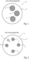
- Fig. 1 shows a cross-section of a first embodiment of the sensor fiber 1, not according to the invention.
- the sensor fiber consists of three individual FBG fiber cores 2, each of which has a fiber Bragg grating (FBG).
- the three FBG fiber cores are surrounded by a cladding 3, whereby the sensor fiber formed thereby has a circular cross-sectional shape in the example presented here.
- Other cross-sectional shapes of the sensor fiber in particular elliptical shapes, are also possible.
- the fiber core located in the 12 o'clock direction forms a first core
- the fiber core located in the 3 o'clock direction the second and the fiber core located at 6 o'clock the third core, whereby it is specified that the asymmetry of the sensor fiber lies in the 9 o'clock direction.
- This asymmetry can be easily detected.
- the orientation of the sensor fiber in an external reference system in particular its angle of rotation, can be arbitrary.
- the individual FBG fiber cores can be addressed, so that their position in relation to the external reference system can be easily corrected by appropriate transformations within the measuring apparatus.
- the corresponding assignment can be made in the measuring device. However, it is important to ensure that the sensor fiber is radiated in the correct direction.
- the in Fig. 1 The asymmetrical arrangement of the FBG fiber cores shown can be determined in a very simple manner during the manufacture of the sensor fiber preform.
- the preform FBG cores are arranged accordingly and surrounded with cladding in the usual way.
- the arrangement of the FBG cores is retained during the subsequent drawing process and marks the asymmetry present in the finished sensor fiber.
- Fig. 2 shows an embodiment not according to the invention with four FBG fiber cores 2 in a cylindrically symmetrical arrangement.
- a marking zone 4 is provided within the cladding 3, which is enclosed between two FBG fiber cores 2 and thus designates a marking point in the cladding.
- the marking zones are areas within the cladding that differ in their properties from the surrounding cladding.
- It is a marking zone with a triangular cross-section. It is relatively small compared to the FBG fiber cores, but sufficiently large to be reliably detected.
- the marking zones can be designed to be light-conducting, without however being used as actual light-conducting cores or sensor cores. Their function essentially consists only in providing and defining an orientation signal and thus a reference point for the entire sensor fiber.
- Fig. 3 One way to add one or more marking zones in Cladding 3 is Fig. 3 shown.
- two capillaries 5 are embedded in the cladding, one of the capillaries being filled with an analyte and/or a marker 6.
- the marker can be, for example, a fluorescent substance whose fluorescent light is registered by a downstream measuring device.
- the capillaries appear as "holes" that are either filled or unfilled.
- a sensor fiber designed as in this example ensures that the individual FBG fiber cores 2 can be distinguished, for example by designating the FBG fiber core arranged between the capillaries as the first core and the FBG fiber cores following it in a clockwise direction as the second, third and fourth FBG fiber cores and can also be detected in this way.
- both capillaries are designed to be distinguishable, so that the direction of radiation through the sensor fiber can be clearly determined, whereby the unique addressing of the individual FBG fiber cores is retained at all times.
- the orientation of the sensor fiber and its individual FBG fiber cores is carried out in such a way that a downstream measuring device registers the light signals coming in from the capillaries 5 and then addresses the individual FBG fiber cores in an internal calibration process.
- FIG. 4 An inventive possibility for marking and addressing the FBG fiber cores is shown Fig. 4 .
- a rod 7 is provided within the cladding 3, which is arranged near one of the FBG fiber cores 2 and induces mechanical stresses in this FBG fiber core. This changes the optical behavior of the corresponding FBG fiber core. This thus forms a reference point that can be clearly detected by a measuring device and from which the other FBG fiber cores can be distinguished and addressed.
- Fig. 5 shows a further possibility not according to the invention for marking and addressing the FBG fiber cores.
- a cylindrically symmetrical arrangement of eight FBG fiber cores 3 is provided within the common cladding 3.
- the eight-fold symmetry is disturbed by the fact that one of the FBG fiber cores has been replaced by a rod 8.
- This rod 8 has in particular the refractive index of the cladding and can also be made of the same material as the cladding.
- the rod can also differ from the cladding in terms of material and refractive index.
- the rod breaks the symmetry of the arrangement of the FBG fiber cores and thus sets a marking reference point.
- Fig. 6 shows a further exemplary embodiment of the sensor fiber 1, not according to the invention, with four FBG fiber cores 2 within the cladding 3.
- one of the FBG fiber cores is provided with a modification 9, which thus sets a reference point for the arrangement of the FBG fiber cores.
- all FBG fiber cores are surrounded by a layer 10 with a reduced refractive index.
- Modification 9 can be achieved in particular by modifying the relevant FBG fiber core by asymmetrical removal of material.
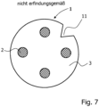
- Fig. 7 shows a non-inventive embodiment of the sensor fiber 1 with four FBG fiber cores 2 within the cladding 3.
- the marking zone is designed as an inhomogeneity 11 within the outer contour of the sensor fiber.
- the inhomogeneity is a depression in the form of a notch.
- the notch within the sensor fiber can be created by milling a sufficiently deep and wide starting notch over the entire length of the preform intended for the production of the sensor fiber at a defined point or by introducing it using other corresponding processing methods. During the subsequent drawing process, the starting notch rounds and flattens somewhat, but remains sufficiently clear and can be used as a detectable marking.
- the individual cores are fused to the surrounding tube.
- the fiber Bragg gratings as well as the modifications to be made to the individual FBG fiber cores can also be written directly into the sensor fiber by cladding during the fiber drawing process.
- the sensor fiber was explained in more detail using exemplary embodiments.
Landscapes
- Physics & Mathematics (AREA)
- General Physics & Mathematics (AREA)
- Optics & Photonics (AREA)
- Optical Transform (AREA)
- Measuring Temperature Or Quantity Of Heat (AREA)
- Length Measuring Devices By Optical Means (AREA)
- Testing Or Calibration Of Command Recording Devices (AREA)
- Optical Fibers, Optical Fiber Cores, And Optical Fiber Bundles (AREA)
Description
- Die Erfindung betrifft eine Sensorfaser zur Temperatur-, Dehnungs- und/oder Torsionsdetektion in Form eines Mehrkern-Lichtwellenleiters mit einer Fiber-Bragg-Gitterstruktur nach dem Oberbegriff des Anspruchs 1.
- Derartige Sensorfasern werden verwendet, um Materialien und Prozesse zu überwachen. Durch das Einschreiben von Fiber-Bragg-Gittern (FBG) in den Faserkern wird eine Sensitivität gegenüber Längen- und/oder Temperaturänderungen erreicht. Durch eine Kombination mehrerer derartiger FBG werden auch Materialdurchbiegungen und - spannungen bestimmbar. Zur Fehlerreduktion infolge einwirkender Umgebungsbedingungen auf die einzelnen FBG, werden mehrere dieser Gitter in einer Faser zusammengefasst, die somit mehrere derartige FBG-Faserkerne enthält.
- Aus dem Stand der Technik sind mehrere Ausführungsformen solcher Mehrkernfasern bekannt. Die
US 5563967 lehrt beispielsweise ein Verfahren zur Herstellung einer Sensorfaser basierend auf einem Design mit zwei FBG-Faserkernen. Mit einer derartigen Sensorfaser ist es möglich, Temperatur- und Längenänderungen simultan zu bestimmen. - Die
WO 2007/143369 A1 offenbart einen optischen Fasersensor in Mehrkernausführung. Gemäß der dort enthaltenen Lehre wird ein Drucksensor in Form einer mehrkernigen optischen Faser beschrieben. Der dort offenbarte Aufbau ist dafür vorgesehen, einen äußeren Druck über die Messung einer Faserbiegung zu bestimmen. Für die Bestimmung der Biegung an der Faser gemäß werden dort beide Faserkerne ausgelesen. Gemäß der dort offenbarten Lehre muss lediglich ein relatives Verhalten beider Faserkerne bestimmbar sein, wobei daraus die Biegung bestimmt wird. Die Position der Faserkerne hingegen ist dort nicht von Bedeutung. - Die
WO 03/005080 A1 - Die
US 7,317,849 B1 offenbart einen optischen Fasersensor und ein Verfahren zum Herstellen eines derartigen Sensors. Die dort vorgesehene Anordnung der FBG-Faserkerne soll zur Detektion von Biegungen innerhalb definierter Ebenen verwendet werden. Gemäß der dort offenbarten Lehre erfolgt die Zuordnung und Orientierung der Faserkerne durch eine äußere Formgebung der Sensorfaser. Diese kann dadurch definiert auf eine entsprechende Fläche aufgelegt werden. - Die
US 2012/0114292 A1 offenbart mehrkernige optische Faserbänder. Bei den dort gezeigten Faserbändern sind mindestens zwei Kerne parallel zueinander in einer Ebene innerhalb eines umgebenden Claddings vereinigt. Jeder der Kerne kann als sogenannter Multimode-Kern ausgebildet sein. Die dort gezeigte Faser keine Sensorfaser und enthält auch keine FBG-Faserkerne. Gegenstand der Druckschrift ist eine zweckmäßige Ausbildung einer bestimmten Faserdichte in einem Faserband. - Die
US 2011/0052129 A1 offenbart eine mehrkernige optische Faser. Gegenstand der Druckschrift ist das Reduzieren eines sogenannten Crosstalks zwischen im gemeinsamen Faserkörper vereinigten Kernen. Die Druckschrift offenbart ein Mehrkernfaser zur Lichtübertragung. Die offenbarten Faserkerne sind keine FBG-Faserkerne. - Die aus dem Stand der Technik bekannten Sensorfasern dieser Art weisen allerdings den Nachteil auf, dass derartige Fasern nicht ohne weiteres eine simultane Messung von Länge, Biegung, Temperatur und Torsion erlauben. Zur Erfassung möglichst umfangreicher Messdaten werden einerseits viele FBG-Faserkerne benötigt und es zeigt sich andererseits, dass die Auswertung der durch die Sensorfaser anfallenden Rohdaten zunehmend komplex wird.
- Es besteht somit die Aufgabe, eine Sensorfaser der genannten Art mit einem möglichst einfachen Aufbau anzugeben, mit denen möglichst viele Messparameter simultan gemessen werden können und mit denen es insbesondere möglich ist, neben Temperatur-, Längen- und Biegeänderungen auch Torsionseffekte messbar zu machen.
- Die Aufgabe wird mit einer Sensorfaser zur Temperatur-, Dehnungs- und/oder Torsionsdetektion in Form eines Mehrkern-Lichtwellenleiters mit einer Fiber-Bragg-Gitterstruktur mit den Merkmalen des Anspruchs 1 gelöst. Diese umfasst mindestens zwei mit der Fiber-Bragg-Gitterstruktur versehene lichtleitende FBG-Faserkerne und ein die FBG-Faserkerne umgebendes gemeinsames Cladding.
- Erfindungsgemäß zeichnet sich die die Sensorfaser aus durch einen innerhalb des Claddings vorhandenen Referenzpunkt in Form von einem oder mehreren innerhalb der Sensorfaser angeordnete Unterscheidungs- und Orientierungsmitteln zum Erzeugen einer jeden einzelnen FBG-Faserkern eindeutig kennzeichnenden Markierung,
wobei die einzelnen in der Sensorfaser zusammengefassten FBG-Faserkerne unterscheidbar sind, sodass die jeweiligen Messsignale aus jedem einzelnen FBG-Faserkern von einer Messapparatur erfassbar und jeder einzelnen Faser eindeutig zuordenbar sind. - Erfindungsgemäß adressieren die Unterscheidungs- und Orientierungsmittel die einzelnen FBG-Faserkerne, sodass in einer der Sensorfaser nachgeschalteten Messapparatur jederzeit eine Information darüber vorliegt, welcher FBG-Faserkern innerhalb der Sensorfaser welches Signal liefert und welcher FBG-Faserkern somit in welcher Weise zum Messsignal beiträgt.
- Erfindungsgemäß ist das ein oder mehrere innerhalb der Sensorfaser angeordnete Unterscheidungs- und Orientierungsmittel in Form von mindestens einer an ausgewählten Positionen innerhalb des Querschnitts der Sensorfaser im Cladding angeordneten, eindeutig detektierbaren Markierungszone ausgebildet, wobei die mindestens eine Markierungszone ein mechanische Spannungen induzierender Stab ist, wobei die mechanischen Spannungen eine eindeutig nachweisbare Änderung der Lichtleiteigenschaften bei einem in der Nähe gelegenen und dadurch markierten FBG-Faserkern bewirken.
- Der der erfindungsgemäßen Sensorfaser zugrunde liegende Gedanke ist es somit, die einzelnen in der Sensorfaser zusammengefassten FBG-Faserkerne unterscheidbar zu gestalten, sodass sich die jeweiligen Messsignale aus jedem einzelnen FBG-Faserkern von einer Messapparatur in einer sehr einfachen Weise erfassen und vor allem jeder einzelnen Faser eindeutig zuordnen lassen. Durch diese Unterscheidungs- und Orientierungsmittel ist es insbesondere möglich, nicht nur Dehnungs-, Längen- und Biegungsmessungen auszuführen, sondern außerdem noch die Temperatur und vor allem eine an der Faser anliegende Torsion zu bestimmen. Letzteres ist dadurch möglich, weil die Unterscheidungs- und Orientierungsmittel die einzelnen FBG-Faserkerne adressieren, sodass in einer der Sensorfaser nachgeschalteten Messapparatur jederzeit eine Information darüber vorliegt, welcher FBG-Faserkern innerhalb der Sensorfaser welches Signal liefert und welcher FBG-Faserkern somit in welcher Weise zum Messsignal beiträgt.
- Bei einer ersten nicht erfindungsgemäßen Ausführungsform ist das Unterscheidungs- und Orientierungsmittel eine nicht zylindersymmetrische Anordnung der einzelnen FBG-Faserkerne innerhalb des Claddings, wobei die FBG-Faserkerne in einer die eindeutige Markierung sichernden Anzahl vorgesehen sind.
- Die einzelnen FBG-Faserkerne sind hierbei über den Querschnitt der Sensorfaser so verteilt, dass deren asymmetrische Anordnung eine eindeutige Unterscheidung der FBG-Faserkerne mit sich bringt.
- Bei einer weiteren Ausführungsform ist das Unterscheidungs- und Orientierungsmittel in Form von an ausgewählten Positionen innerhalb des Querschnitts der Sensorfaser im Cladding angeordneten, eindeutig detektierbaren Markierungszonen ausgebildet. In einem derartigen Fall bietet die Sensorfaser der nachgeschalteten Messapparatur mindestens einen Referenzpunkt bzw. ein Referenzsignal, dass auf die Anordnung der FBG-Faserkerne und damit auf deren Unterscheidbarkeit verweist.
- Die Markierungszonen können auf verschiedene Weise ausgebildet sein.
- Bei einer ersten nicht erfindungsgemäßen Ausführungsform ist die Markierungszone eine in dem Cladding eingebettete Kapillare. Diese zeichnet sich durch ihre "Loch"-Struktur in einer optisch leicht zu detektierenden Weise aus und setzt somit einen Referenzpunkt innerhalb des Querschnitts der Sensorfaser, über den die einzelnen FBG-Faserkerne einzeln unterscheidbar sind.
- Bei einer nicht erfindungsgemäßen Ausführungsform ist die Kapillare mit einem Analyten und/oder einem Marker gefüllt. Dadurch lassen sich an der Kapillare weitere Messsignale ableiten und/oder die Erfassbarkeit des durch die Kapillare gesetzten Referenzpunktes deutlich steigern.
- Erfindungsgemäß ist die Markierungszone als ein mechanische Spannungen induzierender Stab ausgebildet, wobei die mechanischen Spannungen eine eindeutig nachweisbare Änderung der Lichtleiteigenschaften bei einem in der Nähe gelegenen und dadurch markierten FBG-Faserkern bewirken.
- Die Unterscheidung der einzelnen FBG-Faserkerne ist bei dieser Ausführungsform somit dadurch bewirkt, dass mindestens einer der FBG-Faserkerne sich optisch deutlich von den übrigen FBG-Faserkernen unterscheidet und somit als Referenz verwendbar ist, von dem aus die einzelnen anderen FBG-Faserkerne durch die Messapparatur adressierbar sind.
- Bei einer weiteren nicht erfindungsgemäßen Ausführungsform ist die Markierungszone als eine eine gegebene Anordnungssymmetrie der FBG-Faserkerne störende und nicht zu Lichtausbreitung verwendbare Fehlstelle in Form eines aus dem Material des Claddings bestehenden Stabes ausgebildet.
- Die Unterscheidung der einzelnen FBG-Faserkerne wird hier dadurch bewirkt, indem die nachgeschaltete Messapparatur auf eine bestimmte Anordnungssymmetrie der FBG-Faserkerne innerhalb der Sensorfaser eingerichtet ist, aber infolge des aus dem Cladding bestehenden Stabes genau diese Anordnungssymmetrie als gestört detektiert. Diese Störstelle bildet dann einen Referenzpunkt, von dem aus die einzelnen FBG-Faserkerne adressierbar und somit unterscheidbar sind.
- Bei einer weiteren nicht erfindungsgemäßen Ausführungsform ist das Unterscheidungs- und Orientierungsmittel durch ein am jeweiligen FBG-Faserkern ausgebildetes unsymmetrisch abgetragenes Material ausgebildet. Der FBG-Faserkern ist dadurch hinsichtlich seiner optischen Eigenschaften modifiziert und bildet somit einen eindeutig detektierbaren Referenzpunkt zur Adressierung der übrigen FBG-Faserkerne in der Sensorfaser.
- Ergänzend kann jeder einzelner FBG-Faserkern zusätzlich von einer brechzahlabgesenkten eine zwischen den einzelnen FBG-Faserkernen erfolgende Lichtwellenleitung verhindernden Schicht umgeben sein. Dies unterstützt die eindeutige Zuordnung der Messsignale innerhalb der einzelnen FBG-Faserkerne und verbessert die Qualität des jeweiligen Messsignals.
- Die erfindungsgemäße Sensorfaser soll nachfolgend anhand von Ausführungsbeispielen näher erläutert werden. Zur Verdeutlichung dienen die
Figuren 1 bis 6 . Es werden für gleiche bzw. gleichwirkende Teile dieselben Bezugszeichen verwendet. - Es zeigt:
- Fig. 1
- einen Querschnitt eines ersten nicht erfindungsgemäßen Ausführungsbeispiels der Sensorfaser,
- Fig. 2
- einen Querschnitt eines nicht erfindungsgemäßen Ausführungsbeispiels der Sensorfaser mit innerhalb des Claddings angeordneten Markierungszonen,
- Fig. 3
- einen Querschnitt eines nicht erfindungsgemäßen Ausführungsbeispiels der Sensorfaser mit Markierungszonen in Form einer Kapillare mit und ohne Marker und/oder Analyten,
- Fig. 4
- einen Querschnitt eines erfindungsgemäßen Ausführungsbeispiels der Sensorfaser mit einem Stab zum Induzieren mechanischer Spannungen,
- Fig. 5
- einen Querschnitt eines nicht erfindungsgemäßen Ausführungsbeispiels der Sensorfaser mit einer symmetriestörenden Fehlstelle,
- Fig. 6
- einen Querschnitt eines nicht erfindungsgemäßen Ausführungsbeispiels der Sensorfaser mit einem modifizierten FBG-Faserkern,
- Fig. 7
- einen Querschnitt eines nicht erfindungsgemäßen Ausführungsbeispiels der Sensorfaser mit einer in der Außenkontur der Faser angeordneten Inhomogenität.
- Sämtliche nachfolgend beschriebenen Ausführungsformen mit mehreren FBG-Faserkernen werden durch das Zusammenführen von dotierten und/oder undotierten Glasstäben erzeugt. Diese sind entweder Singlemode- oder Multimodepreformen. Weiterhin können auch dotierte/undotierte Glasstäbe eingefügt werden, die als Platzhalter oder zum Induzieren mechanischer Spannungen dienen. Diese Einzelkerne werden in einem Rohr derart angeordnet, dass eine Unterscheidung der einzelnen Kerne auch nach dem Verschmelzen und dem Ziehen der Faser möglich ist. Nachfolgend werden einige beispielhafte Ausführungsformen näher beschrieben.
- Die Größe des Querschnitts der Markierungszonen ist von nicht ausschlaggebender Bedeutung. Sie sollten mindestens so groß sein, um zuverlässig optisch detektiert zu werden. Dabei genügt es insbesondere, dass die Markierungszone hinreichend deutlich als "Fehlstelle" oder "Inhomogenität" erfassbar ist.
-
Fig. 1 zeigt einen Querschnitt eines ersten nicht erfindungsgemäßen Ausführungsbeispiels der Sensorfaser 1. Bei dem hier vorliegenden Beispiel besteht die Sensorfaser aus drei einzelnen FBG-Faserkernen 2, die jeweils ein Faser-Bragg-Gitter (FBG) aufweisen. Die drei FBG-Faserkerne sind von einem Cladding 3 umgeben, wobei die dadurch gebildete Sensorfaser im hier vorliegenden Beispiel eine kreisförmige Querschnittsform aufweist. Andere Querschnittsformen der Sensorfaser, insbesondere elliptische Formen, sind ebenfalls möglich. - Bei der in
Fig. 1 gezeigten Ausführungsform sind drei FBG-Faserkerne im Cladding angeordnet, die untereinander keine zylindersymmetrische Verteilung einnehmen. Das Unterscheidungs- und Orientierungsmittel für die gesamte Sensorfaser und damit die Kennzeichnung jedes einzelnen Sensorkernes wird durch die asymmetrische Verteilung der Sensorkerne gesichert. Dabei bildet beispielsweise der in der Verteilung in der 12-Uhr-Richtung liegende Faserkern einen ersten, der in 3-Uhr-Richtung befindliche Faserkern den zweiten und der bei 6 Uhr liegende Faserkern den dritten Kern, wobei festgelegt ist, dass in der 9 Uhr Richtung die Asymmetrie der Sensorfaser liegt. Diese Asymmetrie kann leicht detektiert werden. Die Orientierung der Sensorfaser in einem äußeren Bezugssystem, insbesondere deren Verdrehwinkel, kann dabei an sich beliebig sein. Sobald die Asymmetrie detektiert worden ist, sind die einzelnen FBG-Faserkerne adressierbar, sodass deren Position zum äußeren Bezugssystem problemlos durch entsprechende Transformationen innerhalb der Messapparatur nachkorrigiert werden kann. Die entsprechende Zuordnung kann in der Messvorrichtung vorgenommen werden. Allerdings ist hierbei auf eine richtige Durchstrahlungsrichtung der Sensorfaser zu achten. - Die in
Fig. 1 gezeigte unsymmetrische Anordnung der FBG-Faserkerne kann in einer sehr einfachen Weise bei der Fertigung der Preform der Sensorfaser festgelegt werden. Dabei werden die Preform-FBG-Kerne entsprechend angeordnet und in der üblichen Weise mit dem Cladding umgeben. Die Anordnung der FBG-Kerne wird beim anschließenden Ziehvorgang beibehalten und markiert in der fertigen Sensorfaser die dort vorliegende Asymmetrie. -
Fig. 2 zeigt eine nicht erfindungsgemäße Ausführungsform mit vier FBG-Faserkernen 2 in einer zylindersymmetrischen Anordnung. Bei dem hier vorliegenden Beispiel ist innerhalb des Claddings 3 eine Markierungszone 4 vorgesehen, die zwischen zwei FBG-Faserkernen 2 eingeschlossen ist und somit eine Markierungsstelle im Cladding bezeichnet. Die Markierungszonen sind Gebiete innerhalb des Claddings, die sich in ihren Eigenschaften vom umgebenden Cladding unterscheiden. Bei der Ausführungsform inFig. 4 handelt es sich um eine Markierungszone mit dreieckigem Querschnitt. Sie ist im Vergleich zu den FBG-Faserkernen relativ klein ausgebildet, aber hinreichend groß, um zuverlässig detektiert zu werden. - Die Markierungszonen können insbesondere lichtleitend ausgeführt sein, ohne dass diese jedoch als eigentliche lichtleitende Kerne oder Sensorkerne Verwendung finden. Ihre Funktion besteht im Wesentlichen nur darin, ein Orientierungssignal und damit einen Referenzpunkt für die gesamte Sensorfaser zu liefern und zu definieren.
- Eine Möglichkeit, eine oder mehrere Markierungszonen im Cladding 3 anzubringen, ist in
Fig. 3 gezeigt. In dem hier vorliegenden nicht erfindungsgemäßen Fall sind zwei Kapillaren 5 in das Cladding eingebettet, wobei eine der Kapillaren mit einem Analyten und/oder einem Marker 6 gefüllt ist. Der Marker kann beispielsweise eine fluoreszierende Substanz sein, deren Fluoreszenzlicht von einer nachgeschalteten Messapparatur registriert wird. Im Querschnitt zeigen sich die Kapillaren als "Löcher", die entweder gefüllt oder ungefüllt sind. Eine wie in diesem Beispiel ausgebildete Sensorfaser sichert einerseits eine Unterscheidbarkeit der einzelnen FBG-Faserkerne 2, etwa dadurch, dass der zwischen den Kapillaren angeordnete FBG-Faserkern als erster Kern und die darauf im Uhrzeigersinn folgenden FBG-Faserkerne als zweiter, dritter und vierter FBG-Faserkern bezeichnet und auch so detektierbar sind. Darüber hinaus sind auch beide Kapillaren unterscheidbar gestaltet, sodass auch die Durchstrahlungsrichtung der Sensorfaser eindeutig feststellbar ist, wobei die eindeutige Adressierung der einzelnen FBG-Faserkerne jederzeit erhalten bleibt. Im Einzelnen wird die Orientierung der Sensorfaser und ihrer einzelnen FBG-Faserkerne so vorgenommen, dass eine nachgeschaltete Messapparatur die von den Kapillaren 5 einlaufenden Lichtsignale entsprechend registriert und in einem internen Kalibrierungsprozess dann die Adressierung der einzelnen FBG-Faserkerne vornimmt. - Eine erfindungsgemäße Möglichkeit zur Markierung und Adressierung der FBG-Faserkerne zeigt
Fig. 4 . Bei dem hier vorliegenden Beispiel ist innerhalb des Claddings 3 ein Stab 7 vorgesehen, der in der Nähe einer der FBG-Faserkerne 2 angeordnet ist und in diesem FBG-Faserkern mechanische Spannungen induziert. Dadurch ändert sich das optische Verhalten des entsprechenden FBG-Faserkerns. Dieser bildet somit einen von einer Messapparatur eindeutig detektierbaren Referenzpunkt, von dem aus die übrigen FBG-Faserkerne unterscheidbar sind und adressiert werden können. -
Fig. 5 zeigt eine weitere nicht erfindungsgemäße Möglichkeit zur Markierung und Adressierung der FBG-Faserkerne. In dem hier vorliegenden Beispiel ist eine zylindersymmetrische Anordnung aus acht FBG-Faserkernen 3 innerhalb des gemeinsamen Claddings 3 vorgesehen. Dabei ist allerdings die achtzählige Symmetrie dadurch gestört, indem einer der FBG-Faserkerne durch einen Stab 8 ersetzt worden ist. Dieser Stab 8 weist insbesondere die Brechzahl des Claddings auf und kann auch aus dem gleichen Material wie das Cladding bestehen. Natürlich kann sich der Stab auch hinsichtlich des Materials und der Brechzahl vom Cladding unterscheiden. In jedem Fall bricht der Stab die Symmetrie der Anordnung der FBG-Faserkerne und setzt somit einen markierenden Referenzpunkt. -
Fig. 6 zeigt eine weitere beispielhafte nicht erfindungsgemäße Ausführungsform der Sensorfaser 1 mit vier FBG-Faserkernen 2 innerhalb des Claddings 3. Bei der hier vorliegenden Ausführungsform ist zum einen einer der FBG-Faserkerne mit einer Modifizierung 9 versehen, die somit einen Referenzpunkt für die Anordnung der FBG-Faserkerne setzt. Zum anderen sind sämtliche FBG-Faserkerne mit eine brechzahlabgesenkten Schicht 10 umgeben. - Die Modifizierung 9 kann insbesondere dadurch erreicht werden, indem der betreffende FBG-Faserkern durch ein unsymmetrisches Abtragen von Material modifiziert wird.
-
Fig. 7 zeigt eine nicht erfindungsgemäße Ausführungsform der Sensorfaser 1 mit vier FBG-Faserkernen 2 innerhalb des Claddings 3. Die Markierungszone ist in diesem Ausführungsbeispiel als eine Inhomogenität 11 innerhalb der Außenkontur der Sensorfaser ausgebildet. Die Inhomogenität ist im hier vorliegenden Fall eine Vertiefung in Form einer Kerbe. Die Kerbe innerhalb der Sensorfaser kann dadurch erzeugt werden, indem in die zur Herstellung der Sensorfaser bestimmte Preform an einer definierten Stelle eine hinreichend tiefe und breite Ausgangskerbe über die gesamte Länge der Preform eingefräst oder durch entsprechend andere Bearbeitungsverfahren eingebracht wird. Beim nachfolgenden Ziehvorgang verrundet und verflacht die Ausgangskerbe etwas, bleibt jedoch hinreichend deutlich erhalten und ist als detektierbare Markierung verwendbar. - Während der Herstellung von Preform und Faser werden die Einzelkerne mit dem umgebenden Rohr verschmolzen. In manchen Fällen können die Faser-Bragg-Gitter wie auch die an den einzelnen FBG-Faserkernen auszuführenden Modifizierungen auch während des Faserziehprozesses direkt durch das Cladding in die Sensorfaser eingeschrieben werden.
- Die Sensorfaser wurde anhand von Ausführungsbeispielen näher erläutert.
- Die Erfindung wird durch die beigefügten Ansprüche definiert.
-
- 1
- Sensorfaser
- 2
- FBG-Faserkern
- 3
- Cladding
- 4
- Markierungszone
- 5
- Kapillare
- 6
- Marker/Analyt
- 7
- spannungsinduzierender Stab
- 8
- Fehlstellenstab
- 9
- Faserkernmodifizierung
- 10
- brechzahlabgesenkte Schicht
- 11
- Inhomogenität in Außenkontur
Claims (2)
- Sensorfaser (1) zur Temperatur-, Dehnungs- und Torsionsdetektion in Form eines Mehrkern-Lichtwellenleiters mit einer Fiber-Bragg-Gitterstruktur, umfassend mindestens zwei mit der Fiber-Bragg-Gitterstruktur versehene lichtleitende FBG-Faserkerne (2) und ein die FBG-Faserkerne umgebendes gemeinsames Cladding (3),
gekennzeichnet durcheinen innerhalb des Claddings vorhandenen Referenzpunkt in Form von einem oder mehreren innerhalb der Sensorfaser angeordnete Unterscheidungs- und Orientierungsmitteln zum Erzeugen einer jeden einzelnen FBG-Faserkern eindeutig kennzeichnenden Markierung,wobei die einzelnen in der Sensorfaser zusammengefassten FBG-Faserkerne unterscheidbar sind, sodass die jeweiligen Messsignale aus jedem einzelnen FBG-Faserkern von einer Messapparatur erfassbar und jeder einzelnen Faser eindeutig zuordenbar sind,wobei die Unterscheidungs- und Orientierungsmittel die einzelnen FBG-Faserkerne adressieren, sodass in einer der Sensorfaser nachgeschalteten Messapparatur jederzeit eine Information darüber vorliegt, welcher FBG-Faserkern innerhalb der Sensorfaser welches Signal liefert und welcher FBG-Faserkern somit in welcher Weise zum Messsignal beiträgt,wobeidas ein oder mehrere innerhalb der Sensorfaser angeordnete Unterscheidungs- und Orientierungsmittel in Form von mindestens einer an ausgewählten Positionen innerhalb des Querschnitts der Sensorfaser (1) im Cladding (3) angeordneten, eindeutig detektierbaren Markierungszone (4) ausgebildet ist,wobeidie mindestens eine Markierungszone ein mechanische Spannungen induzierender Stab (7) ist, wobei die mechanischen Spannungen eine eindeutig nachweisbare Änderung der Lichtleiteigenschaften bei einem in der Nähe gelegenen und dadurch markierten FBG-Faserkern bewirken. - Sensorfaser nach Anspruch 1,
dadurch gekennzeichnet, dass
jeder einzelne FBG-Faserkern (2) von einer brechzahlabgesenkten, eine zwischen den einzelnen FBG-Faserkernen erfolgende Lichtwellenleitung verhindernde Schicht (10) umgeben ist.
Applications Claiming Priority (1)
| Application Number | Priority Date | Filing Date | Title |
|---|---|---|---|
| DE102012106806.2A DE102012106806B4 (de) | 2012-07-26 | 2012-07-26 | Sensorfaser zur Temperatur-, Dehnungs- und/oder Torsionsdetektion in Form eines Mehrkern-Lichtwellenleiters mit einer Fiber-Bragg-Gitterstruktur |
Publications (3)
| Publication Number | Publication Date |
|---|---|
| EP2690421A2 EP2690421A2 (de) | 2014-01-29 |
| EP2690421A3 EP2690421A3 (de) | 2014-03-12 |
| EP2690421B1 true EP2690421B1 (de) | 2024-12-11 |
Family
ID=48900754
Family Applications (1)
| Application Number | Title | Priority Date | Filing Date |
|---|---|---|---|
| EP13177029.9A Active EP2690421B1 (de) | 2012-07-26 | 2013-07-18 | Sensorfaser zur Temperatur-, Dehnungs- und/oder Torsionsdetektion in Form eines Mehrkern-Lichtwellenleiters mit einer Fiber-Bragg-Gitterstruktur |
Country Status (4)
| Country | Link |
|---|---|
| US (1) | US9976880B2 (de) |
| EP (1) | EP2690421B1 (de) |
| JP (1) | JP5654646B2 (de) |
| DE (1) | DE102012106806B4 (de) |
Families Citing this family (22)
| Publication number | Priority date | Publication date | Assignee | Title |
|---|---|---|---|---|
| US9810557B2 (en) * | 2014-02-10 | 2017-11-07 | University Of Central Florida Research Foundation, Inc. | Multicore optical fiber apparatus, methods, and applications |
| JP6204847B2 (ja) | 2014-02-13 | 2017-09-27 | 山洋電気株式会社 | モータのアース線接続構造 |
| DE102014224964B4 (de) | 2014-05-12 | 2023-06-01 | J-Fiber Gmbh | Verfahren zur Herstellung einer polarisationserhaltenden Lichtleitfaser, Preform zur Herstellung einer polarisationserhaltenden Lichtleitfaser und polarisationserhaltende Lichtleitfaser |
| CN105784184A (zh) * | 2016-03-16 | 2016-07-20 | 重庆大学 | 高温拉伸试验中一种温度-应变的一体化测量方法 |
| CN106959077A (zh) * | 2017-03-06 | 2017-07-18 | 哈尔滨工程大学 | 一种多芯光纤光栅万向弯曲传感器 |
| US10612982B2 (en) | 2017-05-23 | 2020-04-07 | Kidde Technologies, Inc. | Modular sensing fiber optic cables |
| CN108332876B (zh) * | 2018-01-30 | 2020-05-19 | 华中科技大学 | 一种光纤温度传感器 |
| WO2020082253A1 (zh) * | 2018-10-24 | 2020-04-30 | 深圳大学 | 多芯光纤压力传感器、传感系统和传感器制备方法 |
| EP3705020A1 (de) * | 2019-03-05 | 2020-09-09 | FBGS Technologies GmbH | Verfahren und systeme zur formerfassung |
| CN110986836B (zh) * | 2019-10-30 | 2022-03-22 | 桂林电子科技大学 | 基于环形芯光纤的高精度粗糙度测量装置 |
| CN111307076A (zh) * | 2019-10-30 | 2020-06-19 | 桂林电子科技大学 | 一种多芯光纤微纳图形辨识装置 |
| CN111307075B (zh) * | 2019-10-30 | 2022-03-25 | 桂林电子科技大学 | 可识别纹理方向的粗糙度测量装置 |
| CN112762861B (zh) * | 2019-11-04 | 2022-11-08 | 聊城大学 | 多芯光纤感测组件及多芯光纤感测系统 |
| JP7389644B2 (ja) | 2019-12-26 | 2023-11-30 | 株式会社フジクラ | マルチコアファイバ、光ファイバケーブル、及び光コネクタ |
| CN111897046A (zh) * | 2020-09-18 | 2020-11-06 | 长飞光纤光缆股份有限公司 | 一种便于识别和对接的多芯光纤 |
| JP2022124320A (ja) * | 2021-02-15 | 2022-08-25 | Kddi株式会社 | マルチコア光ファイバ |
| EP4212489A1 (de) * | 2022-01-18 | 2023-07-19 | Heraeus Quarzglas GmbH & Co. KG | Verfahren und halbzeug zur herstellung einer mehrkernfaser |
| EP4212488A1 (de) * | 2022-01-18 | 2023-07-19 | Heraeus Quarzglas GmbH & Co. KG | Verfahren und halbzeug zur herstellung einer mehrkernfaser |
| CN114878858B (zh) * | 2022-07-11 | 2022-11-18 | 之江实验室 | 基于多芯光纤光栅的建筑拉索摆动加速度测量装置及方法 |
| WO2025094480A1 (ja) * | 2023-11-02 | 2025-05-08 | 株式会社フジクラ | 光ファイバ |
| CN117433587B (zh) * | 2023-12-14 | 2024-03-19 | 江苏南方通信科技有限公司 | 对称结构多参数弱光栅传感光缆、传感系统和测量方法 |
| WO2025173711A1 (ja) * | 2024-02-13 | 2025-08-21 | 住友電気工業株式会社 | 光ファイバ、光ファイバの製造方法、テープファイバ、および、テープファイバの製造方法 |
Family Cites Families (42)
| Publication number | Priority date | Publication date | Assignee | Title |
|---|---|---|---|---|
| JPS5813505U (ja) * | 1981-07-17 | 1983-01-27 | 日本電信電話株式会社 | マルチコア光フアイバ |
| JPS6227307U (de) * | 1985-08-05 | 1987-02-19 | ||
| JPS6326806U (de) * | 1986-08-01 | 1988-02-22 | ||
| JPS6349707A (ja) * | 1986-08-20 | 1988-03-02 | Sumitomo Electric Ind Ltd | 通信用光フアイバ |
| US5144690A (en) * | 1990-12-03 | 1992-09-01 | Corning Incorporated | Optical fiber sensor with localized sensing regions |
| JPH06138328A (ja) * | 1992-10-26 | 1994-05-20 | Fujikura Ltd | イメージファイバ |
| JP2005222087A (ja) * | 1994-04-08 | 2005-08-18 | Olympus Corp | イメージファイバー及びその製造方法 |
| WO1995032442A1 (en) * | 1994-05-24 | 1995-11-30 | Asahi Kasei Kogyo Kabushiki Kaisha | Plastic fiber bundle for optical communication |
| US5557400A (en) * | 1995-02-15 | 1996-09-17 | Hewlett-Packard Company | Multiplexed sensing using optical coherence reflectrometry |
| US5563967A (en) | 1995-06-07 | 1996-10-08 | Mcdonnell Douglas Corporation | Fiber optic sensor having a multicore optical fiber and an associated sensing method |
| US6301420B1 (en) * | 1998-05-01 | 2001-10-09 | The Secretary Of State For Defence In Her Britannic Majesty's Government Of The United Kingdom Of Great Britain And Northern Ireland | Multicore optical fibre |
| US6826343B2 (en) * | 2001-03-16 | 2004-11-30 | Cidra Corporation | Multi-core waveguide |
| SE520249C2 (sv) * | 2001-07-02 | 2003-06-17 | Acreo Ab | Förfarande för anordnande av en longitudinell, fast kropp inuti en fiber |
| FR2839559B1 (fr) * | 2002-05-13 | 2004-11-05 | Teem Photonics | Multiplexeur/demultiplexeur en optique integree comportant une gaine optique et son procede de realisation |
| DE10237361B4 (de) * | 2002-08-12 | 2007-07-19 | Deutsches Zentrum für Luft- und Raumfahrt e.V. | Verfahren zur Herstellung eines faseroptischen Sensors und damit hergestellter Sensor |
| US7027699B2 (en) * | 2003-05-21 | 2006-04-11 | The Hong Kong Polytechnic University | Optical fiber and optical fiber sensors |
| US8018636B2 (en) * | 2003-12-10 | 2011-09-13 | Nippon Telegraph And Telephone Corporation | Laminated holographic medium, recording apparatus/method, reproduction apparatus/method for the same and design method of laminated hologram medium |
| US7772541B2 (en) * | 2004-07-16 | 2010-08-10 | Luna Innnovations Incorporated | Fiber optic position and/or shape sensing based on rayleigh scatter |
| US7430352B2 (en) * | 2005-07-29 | 2008-09-30 | Aculight Corporation | Multi-segment photonic-crystal-rod waveguides for amplification of high-power pulsed optical radiation and associated method |
| US7391561B2 (en) * | 2005-07-29 | 2008-06-24 | Aculight Corporation | Fiber- or rod-based optical source featuring a large-core, rare-earth-doped photonic-crystal device for generation of high-power pulsed radiation and method |
| US20070265503A1 (en) * | 2006-03-22 | 2007-11-15 | Hansen Medical, Inc. | Fiber optic instrument sensing system |
| US7310456B1 (en) * | 2006-06-02 | 2007-12-18 | Baker Hughes Incorporated | Multi-core optical fiber pressure sensor |
| US7664347B2 (en) * | 2006-06-07 | 2010-02-16 | Baker Hughes Incorporated | Multi-core optical fiber sensor |
| US7317849B1 (en) * | 2006-06-08 | 2008-01-08 | Institut National D'optique | Optical fiber sensor and method |
| US7379631B2 (en) * | 2006-06-12 | 2008-05-27 | Baker Hughes Incorporated | Multi-core distributed temperature sensing fiber |
| WO2008080174A1 (en) | 2006-12-27 | 2008-07-03 | Chiral Photonics, Inc. | Single helix chiral fiber grating |
| US8050523B2 (en) * | 2007-04-20 | 2011-11-01 | Koninklijke Philips Electronics N.V. | Optical fiber shape sensing systems |
| WO2009023801A1 (en) * | 2007-08-14 | 2009-02-19 | Hansen Medical, Inc. | Robotic instrument systems and methods utilizing optical fiber sensor |
| US8009946B2 (en) * | 2008-01-22 | 2011-08-30 | General Electric Company | Fiberoptic patient health multi-parameter monitoring devices and system |
| US8123400B2 (en) * | 2008-04-16 | 2012-02-28 | Ofs Fitel, Llc | Multi-core fiber grating sensor |
| CA2709099C (en) * | 2008-06-18 | 2017-06-13 | Mako Surgical Corp. | Fiber optic tracking system and method for tracking |
| US7720322B2 (en) * | 2008-06-30 | 2010-05-18 | Intuitive Surgical, Inc. | Fiber optic shape sensor |
| EP2369380A4 (de) * | 2008-12-24 | 2014-04-16 | Furukawa Electric Co Ltd | Multikern-glasfaser |
| CN102282488B (zh) * | 2009-01-19 | 2014-04-23 | 住友电气工业株式会社 | 多芯光纤 |
| US8773650B2 (en) * | 2009-09-18 | 2014-07-08 | Intuitive Surgical Operations, Inc. | Optical position and/or shape sensing |
| JP2011180133A (ja) * | 2010-02-03 | 2011-09-15 | Soka Univ | 光ファイバセンサ及びその製造方法 |
| JP5267481B2 (ja) | 2010-02-18 | 2013-08-21 | 住友電気工業株式会社 | マルチコア光ファイバ |
| JP5471776B2 (ja) | 2010-03-17 | 2014-04-16 | 住友電気工業株式会社 | マルチコア光ファイバ |
| US8672837B2 (en) * | 2010-06-24 | 2014-03-18 | Hansen Medical, Inc. | Methods and devices for controlling a shapeable medical device |
| US9120693B2 (en) * | 2010-11-08 | 2015-09-01 | Corning Incorporated | Multi-core optical fiber ribbons and methods for making the same |
| US8746076B2 (en) * | 2012-08-22 | 2014-06-10 | The United States Of America As Represented By The Administrator Of The National Aeronautics And Space Administration | Shape sensing using a multi-core optical fiber having an arbitrary initial shape in the presence of extrinsic forces |
| US9341532B2 (en) * | 2014-03-24 | 2016-05-17 | General Electric Company | Systems and methods for distributed pressure sensing |
-
2012
- 2012-07-26 DE DE102012106806.2A patent/DE102012106806B4/de active Active
-
2013
- 2013-07-18 EP EP13177029.9A patent/EP2690421B1/de active Active
- 2013-07-24 JP JP2013153938A patent/JP5654646B2/ja active Active
- 2013-07-26 US US13/952,009 patent/US9976880B2/en active Active
Also Published As
| Publication number | Publication date |
|---|---|
| US20140029889A1 (en) | 2014-01-30 |
| JP2014025928A (ja) | 2014-02-06 |
| DE102012106806B4 (de) | 2022-07-28 |
| JP5654646B2 (ja) | 2015-01-14 |
| EP2690421A3 (de) | 2014-03-12 |
| EP2690421A2 (de) | 2014-01-29 |
| US9976880B2 (en) | 2018-05-22 |
| DE102012106806A1 (de) | 2014-01-30 |
Similar Documents
| Publication | Publication Date | Title |
|---|---|---|
| DE102012106806B4 (de) | Sensorfaser zur Temperatur-, Dehnungs- und/oder Torsionsdetektion in Form eines Mehrkern-Lichtwellenleiters mit einer Fiber-Bragg-Gitterstruktur | |
| DE69424365T2 (de) | Lichwelleneleitersensor und Verfahren zu seiner Herstellung | |
| DE10012291C1 (de) | Verfahren zur faseroptischen Temperaturmessung und faseroptischer Temperatursensor | |
| EP2491883B1 (de) | Katheter und Katheteranordnung | |
| EP3497409B1 (de) | Verfahren zur bestimmung der krümmung und/oder torsion eines lichtwellenleiters | |
| EP2979057A1 (de) | Faseroptischer sensor und dessen verwendung | |
| WO2010003632A1 (de) | Temperaturmessung in einer kokille durch ein faseroptisches messverfahren | |
| DE3630163C2 (de) | Zentriervorrichung zum Zentrieren von Lichtleiter-Fasern während des Schweissens | |
| DE3311472A1 (de) | Verfahren zum betrachten einer transparenten stange | |
| EP3420550A1 (de) | Siegel und verfahren zur versiegelung | |
| EP3811135A1 (de) | Vorrichtung und verfahren zur ausrichtung von polarisationserhaltenden lichtleitfasern | |
| DE69830547T2 (de) | Mehrkernfaser | |
| DE102009039259A1 (de) | Überwachung von Walzenlagern | |
| DE102019132569B3 (de) | Multikernfaser mit Multikern-Faserkomponenten sowie Verfahren zu ihrer Herstellung | |
| DE102017201523A1 (de) | Faseroptische Erfassungseinrichtung sowie Verfahren zum Betreiben einer solchen faseroptischen Erfassungseinrichtung | |
| DE102011014915B4 (de) | Verfahren zur Herstellung eines Lichtwellenleiters mit einem optimierbaren Makrokrümmungsverlust und Preform zur Herstellung eines Lichtwellenleiters | |
| WO2019180161A1 (de) | Temperatursensor | |
| DE3942556C2 (de) | ||
| WO2013067996A1 (de) | Optische faser zum gefilterten sammeln von licht, insbesondere von raman-streustrahlung und verfahren zu ihrer herstellung | |
| DE102011080328B4 (de) | Wellenleiter und Verbindungselement | |
| DE19512483C2 (de) | Verfahren zur kontinuierlichen Herstellung eines im Querschnitt kreisförmigen Kabelelementes zur Übertragung optischer Signale | |
| DE19502007C2 (de) | Verfahren zum Herstellen eines Sensorkopfes für eine Temperaturmeßvorrichtung | |
| EP2779931B1 (de) | Vorrichtung zur medizinischen behandlung, insbesondere eines gewebes, mittels laserlicht | |
| DE102018112739A1 (de) | Verfahren zum Herstellen einer Preform zum Herstellen einer Mehrkernfaser sowie Preform und Mehrkernfaser | |
| DE102015118010A1 (de) | Herstellung eines Faserkopplers |
Legal Events
| Date | Code | Title | Description |
|---|---|---|---|
| PUAI | Public reference made under article 153(3) epc to a published international application that has entered the european phase |
Free format text: ORIGINAL CODE: 0009012 |
|
| AK | Designated contracting states |
Kind code of ref document: A2 Designated state(s): AL AT BE BG CH CY CZ DE DK EE ES FI FR GB GR HR HU IE IS IT LI LT LU LV MC MK MT NL NO PL PT RO RS SE SI SK SM TR |
|
| AX | Request for extension of the european patent |
Extension state: BA ME |
|
| PUAL | Search report despatched |
Free format text: ORIGINAL CODE: 0009013 |
|
| AK | Designated contracting states |
Kind code of ref document: A3 Designated state(s): AL AT BE BG CH CY CZ DE DK EE ES FI FR GB GR HR HU IE IS IT LI LT LU LV MC MK MT NL NO PL PT RO RS SE SI SK SM TR |
|
| AX | Request for extension of the european patent |
Extension state: BA ME |
|
| RIC1 | Information provided on ipc code assigned before grant |
Ipc: G01B 11/16 20060101ALI20140203BHEP Ipc: G01M 11/08 20060101AFI20140203BHEP Ipc: G01D 5/353 20060101ALI20140203BHEP Ipc: G02B 6/00 20060101ALI20140203BHEP Ipc: G01L 1/24 20060101ALI20140203BHEP |
|
| 17P | Request for examination filed |
Effective date: 20140905 |
|
| RBV | Designated contracting states (corrected) |
Designated state(s): AL AT BE BG CH CY CZ DE DK EE ES FI FR GB GR HR HU IE IS IT LI LT LU LV MC MK MT NL NO PL PT RO RS SE SI SK SM TR |
|
| RIN1 | Information on inventor provided before grant (corrected) |
Inventor name: HANF, ROBERT Inventor name: ROESSNER, KATRIN Inventor name: BREHM, LOTHAR Inventor name: LANDERS, ARMIN Inventor name: ROSENOW, RALITSA Inventor name: BERNAUER, OTTO Inventor name: ROSENKRANZ, JUERGEN |
|
| STAA | Information on the status of an ep patent application or granted ep patent |
Free format text: STATUS: EXAMINATION IS IN PROGRESS |
|
| 17Q | First examination report despatched |
Effective date: 20180903 |
|
| P01 | Opt-out of the competence of the unified patent court (upc) registered |
Effective date: 20230528 |
|
| REG | Reference to a national code |
Ref country code: DE Ref legal event code: R079 Free format text: PREVIOUS MAIN CLASS: G01M0011080000 Ipc: G01B0011160000 Ref country code: DE Ref legal event code: R079 Ref document number: 502013016559 Country of ref document: DE Free format text: PREVIOUS MAIN CLASS: G01M0011080000 Ipc: G01B0011160000 |
|
| GRAP | Despatch of communication of intention to grant a patent |
Free format text: ORIGINAL CODE: EPIDOSNIGR1 |
|
| STAA | Information on the status of an ep patent application or granted ep patent |
Free format text: STATUS: GRANT OF PATENT IS INTENDED |
|
| RIC1 | Information provided on ipc code assigned before grant |
Ipc: G02B 6/02 20060101ALN20240729BHEP Ipc: G01L 3/12 20060101ALI20240729BHEP Ipc: G01K 11/3206 20210101ALI20240729BHEP Ipc: G01D 5/353 20060101ALI20240729BHEP Ipc: G01L 1/24 20060101ALI20240729BHEP Ipc: G01B 11/16 20060101AFI20240729BHEP |
|
| INTG | Intention to grant announced |
Effective date: 20240808 |
|
| GRAS | Grant fee paid |
Free format text: ORIGINAL CODE: EPIDOSNIGR3 |
|
| GRAA | (expected) grant |
Free format text: ORIGINAL CODE: 0009210 |
|
| STAA | Information on the status of an ep patent application or granted ep patent |
Free format text: STATUS: THE PATENT HAS BEEN GRANTED |
|
| AK | Designated contracting states |
Kind code of ref document: B1 Designated state(s): AL AT BE BG CH CY CZ DE DK EE ES FI FR GB GR HR HU IE IS IT LI LT LU LV MC MK MT NL NO PL PT RO RS SE SI SK SM TR |
|
| REG | Reference to a national code |
Ref country code: GB Ref legal event code: FG4D Free format text: NOT ENGLISH |
|
| REG | Reference to a national code |
Ref country code: CH Ref legal event code: EP |
|
| REG | Reference to a national code |
Ref country code: IE Ref legal event code: FG4D Free format text: LANGUAGE OF EP DOCUMENT: GERMAN |
|
| REG | Reference to a national code |
Ref country code: DE Ref legal event code: R096 Ref document number: 502013016559 Country of ref document: DE |
|
| REG | Reference to a national code |
Ref country code: LT Ref legal event code: MG9D |
|
| PG25 | Lapsed in a contracting state [announced via postgrant information from national office to epo] |
Ref country code: HR Free format text: LAPSE BECAUSE OF FAILURE TO SUBMIT A TRANSLATION OF THE DESCRIPTION OR TO PAY THE FEE WITHIN THE PRESCRIBED TIME-LIMIT Effective date: 20241211 |
|
| PG25 | Lapsed in a contracting state [announced via postgrant information from national office to epo] |
Ref country code: FI Free format text: LAPSE BECAUSE OF FAILURE TO SUBMIT A TRANSLATION OF THE DESCRIPTION OR TO PAY THE FEE WITHIN THE PRESCRIBED TIME-LIMIT Effective date: 20241211 |
|
| PG25 | Lapsed in a contracting state [announced via postgrant information from national office to epo] |
Ref country code: BG Free format text: LAPSE BECAUSE OF FAILURE TO SUBMIT A TRANSLATION OF THE DESCRIPTION OR TO PAY THE FEE WITHIN THE PRESCRIBED TIME-LIMIT Effective date: 20241211 |
|
| REG | Reference to a national code |
Ref country code: NL Ref legal event code: MP Effective date: 20241211 |
|
| PG25 | Lapsed in a contracting state [announced via postgrant information from national office to epo] |
Ref country code: ES Free format text: LAPSE BECAUSE OF FAILURE TO SUBMIT A TRANSLATION OF THE DESCRIPTION OR TO PAY THE FEE WITHIN THE PRESCRIBED TIME-LIMIT Effective date: 20241211 |
|
| PG25 | Lapsed in a contracting state [announced via postgrant information from national office to epo] |
Ref country code: NO Free format text: LAPSE BECAUSE OF FAILURE TO SUBMIT A TRANSLATION OF THE DESCRIPTION OR TO PAY THE FEE WITHIN THE PRESCRIBED TIME-LIMIT Effective date: 20250311 |
|
| PG25 | Lapsed in a contracting state [announced via postgrant information from national office to epo] |
Ref country code: LV Free format text: LAPSE BECAUSE OF FAILURE TO SUBMIT A TRANSLATION OF THE DESCRIPTION OR TO PAY THE FEE WITHIN THE PRESCRIBED TIME-LIMIT Effective date: 20241211 Ref country code: GR Free format text: LAPSE BECAUSE OF FAILURE TO SUBMIT A TRANSLATION OF THE DESCRIPTION OR TO PAY THE FEE WITHIN THE PRESCRIBED TIME-LIMIT Effective date: 20250312 |
|
| PG25 | Lapsed in a contracting state [announced via postgrant information from national office to epo] |
Ref country code: RS Free format text: LAPSE BECAUSE OF FAILURE TO SUBMIT A TRANSLATION OF THE DESCRIPTION OR TO PAY THE FEE WITHIN THE PRESCRIBED TIME-LIMIT Effective date: 20250311 |
|
| PG25 | Lapsed in a contracting state [announced via postgrant information from national office to epo] |
Ref country code: NL Free format text: LAPSE BECAUSE OF FAILURE TO SUBMIT A TRANSLATION OF THE DESCRIPTION OR TO PAY THE FEE WITHIN THE PRESCRIBED TIME-LIMIT Effective date: 20241211 |
|
| PG25 | Lapsed in a contracting state [announced via postgrant information from national office to epo] |
Ref country code: SM Free format text: LAPSE BECAUSE OF FAILURE TO SUBMIT A TRANSLATION OF THE DESCRIPTION OR TO PAY THE FEE WITHIN THE PRESCRIBED TIME-LIMIT Effective date: 20241211 |
|
| PG25 | Lapsed in a contracting state [announced via postgrant information from national office to epo] |
Ref country code: PL Free format text: LAPSE BECAUSE OF FAILURE TO SUBMIT A TRANSLATION OF THE DESCRIPTION OR TO PAY THE FEE WITHIN THE PRESCRIBED TIME-LIMIT Effective date: 20241211 |
|
| PG25 | Lapsed in a contracting state [announced via postgrant information from national office to epo] |
Ref country code: IS Free format text: LAPSE BECAUSE OF FAILURE TO SUBMIT A TRANSLATION OF THE DESCRIPTION OR TO PAY THE FEE WITHIN THE PRESCRIBED TIME-LIMIT Effective date: 20250411 |
|
| PG25 | Lapsed in a contracting state [announced via postgrant information from national office to epo] |
Ref country code: PT Free format text: LAPSE BECAUSE OF FAILURE TO SUBMIT A TRANSLATION OF THE DESCRIPTION OR TO PAY THE FEE WITHIN THE PRESCRIBED TIME-LIMIT Effective date: 20250411 |
|
| PG25 | Lapsed in a contracting state [announced via postgrant information from national office to epo] |
Ref country code: EE Free format text: LAPSE BECAUSE OF FAILURE TO SUBMIT A TRANSLATION OF THE DESCRIPTION OR TO PAY THE FEE WITHIN THE PRESCRIBED TIME-LIMIT Effective date: 20241211 |
|
| PG25 | Lapsed in a contracting state [announced via postgrant information from national office to epo] |
Ref country code: RO Free format text: LAPSE BECAUSE OF FAILURE TO SUBMIT A TRANSLATION OF THE DESCRIPTION OR TO PAY THE FEE WITHIN THE PRESCRIBED TIME-LIMIT Effective date: 20241211 |
|
| PG25 | Lapsed in a contracting state [announced via postgrant information from national office to epo] |
Ref country code: SK Free format text: LAPSE BECAUSE OF FAILURE TO SUBMIT A TRANSLATION OF THE DESCRIPTION OR TO PAY THE FEE WITHIN THE PRESCRIBED TIME-LIMIT Effective date: 20241211 |
|
| PG25 | Lapsed in a contracting state [announced via postgrant information from national office to epo] |
Ref country code: CZ Free format text: LAPSE BECAUSE OF FAILURE TO SUBMIT A TRANSLATION OF THE DESCRIPTION OR TO PAY THE FEE WITHIN THE PRESCRIBED TIME-LIMIT Effective date: 20241211 |
|
| PG25 | Lapsed in a contracting state [announced via postgrant information from national office to epo] |
Ref country code: IT Free format text: LAPSE BECAUSE OF FAILURE TO SUBMIT A TRANSLATION OF THE DESCRIPTION OR TO PAY THE FEE WITHIN THE PRESCRIBED TIME-LIMIT Effective date: 20241211 |
|
| PG25 | Lapsed in a contracting state [announced via postgrant information from national office to epo] |
Ref country code: SE Free format text: LAPSE BECAUSE OF FAILURE TO SUBMIT A TRANSLATION OF THE DESCRIPTION OR TO PAY THE FEE WITHIN THE PRESCRIBED TIME-LIMIT Effective date: 20241211 |
|
| REG | Reference to a national code |
Ref country code: DE Ref legal event code: R097 Ref document number: 502013016559 Country of ref document: DE |
|
| PG25 | Lapsed in a contracting state [announced via postgrant information from national office to epo] |
Ref country code: DK Free format text: LAPSE BECAUSE OF FAILURE TO SUBMIT A TRANSLATION OF THE DESCRIPTION OR TO PAY THE FEE WITHIN THE PRESCRIBED TIME-LIMIT Effective date: 20241211 |
|
| PGFP | Annual fee paid to national office [announced via postgrant information from national office to epo] |
Ref country code: DE Payment date: 20250722 Year of fee payment: 13 |
|
| PLBE | No opposition filed within time limit |
Free format text: ORIGINAL CODE: 0009261 |
|
| STAA | Information on the status of an ep patent application or granted ep patent |
Free format text: STATUS: NO OPPOSITION FILED WITHIN TIME LIMIT |
|
| PGFP | Annual fee paid to national office [announced via postgrant information from national office to epo] |
Ref country code: FR Payment date: 20250723 Year of fee payment: 13 |
|
| REG | Reference to a national code |
Ref country code: CH Ref legal event code: L10 Free format text: ST27 STATUS EVENT CODE: U-0-0-L10-L00 (AS PROVIDED BY THE NATIONAL OFFICE) Effective date: 20251022 |
|
| 26N | No opposition filed |
Effective date: 20250912 |
|
| REG | Reference to a national code |
Ref country code: CH Ref legal event code: H13 Free format text: ST27 STATUS EVENT CODE: U-0-0-H10-H13 (AS PROVIDED BY THE NATIONAL OFFICE) Effective date: 20260224 |
|
| PG25 | Lapsed in a contracting state [announced via postgrant information from national office to epo] |
Ref country code: LU Free format text: LAPSE BECAUSE OF NON-PAYMENT OF DUE FEES Effective date: 20250718 |
|
| GBPC | Gb: european patent ceased through non-payment of renewal fee |
Effective date: 20250718 |
|
| REG | Reference to a national code |
Ref country code: BE Ref legal event code: MM Effective date: 20250731 |
|
| PG25 | Lapsed in a contracting state [announced via postgrant information from national office to epo] |
Ref country code: GB Free format text: LAPSE BECAUSE OF NON-PAYMENT OF DUE FEES Effective date: 20250718 |
|
| PG25 | Lapsed in a contracting state [announced via postgrant information from national office to epo] |
Ref country code: BE Free format text: LAPSE BECAUSE OF NON-PAYMENT OF DUE FEES Effective date: 20250731 |
|
| PG25 | Lapsed in a contracting state [announced via postgrant information from national office to epo] |
Ref country code: CH Free format text: LAPSE BECAUSE OF NON-PAYMENT OF DUE FEES Effective date: 20250731 |