EP2690367B2 - Revêtement - Google Patents
Revêtement Download PDFInfo
- Publication number
- EP2690367B2 EP2690367B2 EP13177420.0A EP13177420A EP2690367B2 EP 2690367 B2 EP2690367 B2 EP 2690367B2 EP 13177420 A EP13177420 A EP 13177420A EP 2690367 B2 EP2690367 B2 EP 2690367B2
- Authority
- EP
- European Patent Office
- Prior art keywords
- tab
- cover
- opening
- domestic appliance
- telescopic rail
- Prior art date
- Legal status (The legal status is an assumption and is not a legal conclusion. Google has not performed a legal analysis and makes no representation as to the accuracy of the status listed.)
- Active
Links
Images


Classifications
-
- F—MECHANICAL ENGINEERING; LIGHTING; HEATING; WEAPONS; BLASTING
- F24—HEATING; RANGES; VENTILATING
- F24C—DOMESTIC STOVES OR RANGES ; DETAILS OF DOMESTIC STOVES OR RANGES, OF GENERAL APPLICATION
- F24C15/00—Details
- F24C15/16—Shelves, racks or trays inside ovens; Supports therefor
- F24C15/168—Shelves, racks or trays inside ovens; Supports therefor with telescopic rail systems
Definitions
- the present invention relates to a telescopic rail with a first and at least one further rail element, the first rail element being able to be pulled out of the household appliance when the telescopic rail is fastened in a household appliance and having a tab at its end pointing towards the opening of the household appliance, which is perpendicular to the Extension direction of the telescopic rail extends.
- Telescopic rails of the type mentioned are known in the prior art. They are used in various household appliances, including dishwashers, microwaves, ovens, steamers, etc. Such telescopic rails are used in these appliances to hold and pull out inserts, for example food supports, including baking trays and grates. In household appliances that are used to heat objects, especially food, the entire interior of the household appliance is usually heated.
- the telescopic rails mentioned at the outset usually consist of a metal or a metal alloy, optionally with a coating, with the telescopic rail also heating up when the interior of the household appliance is heated.
- a baking tray resting on a pair of telescopic rails can be completely or partially moved outside of the oven with the aid of the telescopic rails.
- the baking tray can be easily removed in this state, it being necessary to move the extended rail elements of the telescopic rail back into the oven interior before closing the oven door.
- the rail elements which are also heated by the high temperatures inside the oven, including the adjoining brackets, which may also be made of a metal or a metal alloy, can cause burn injuries to a user when the rail elements are pushed back, especially if a pot holder or similar heat protection is used.
- the DE 20 2008 014 790U1 relates to a pull-out guide, in particular for ovens, with a guide rail on which at least one further rail is movably mounted via rolling bodies, the rolling bodies being guided along raceways on the rails.
- a plug is fixed to the running rail.
- the EP 2 314 934 relates to a device for receiving a food support for a household appliance, a household appliance, in particular an oven, with such a device and a method for operating such a device.
- a front stop for the food support can be formed at the front end of the second rail, which is a cover cap that is placed on the second rail.
- This cover cap is preferably made of a plastic, in particular a poorly or non-thermally conductive plastic, and as a result contact points between the rail and a part thereof and the food support can be made to be weakly or non-thermally conductive, so that excessive heating via these contact points can be avoided.
- the present invention is based on the object of providing a telescopic rail, the handling of which does not involve any risk of burns, or the risk of burns is reduced.
- this object is achieved in that the tab has a cover on at least one surface facing the opening of the household appliance, which consists of a material that is less thermally conductive than the material from which the tab is made, the cover having a or has a plurality of fastening sections which/which extend/extend at least in sections over a surface of the lug facing away from the opening of the household appliance.
- the tab has a cover on at least one surface facing the opening of the household appliance, which consists of a material that is less thermally conductive than the material from which the tab is made, the cover consists of silicone.
- the tab has a cover on at least one surface facing the opening of the household appliance, which is made of a material that is less heat-conducting than the material from which the tab is made, the cover has a material thickness of about 1 mm to about 3 mm.
- the surface that is usually touched by a user of the household appliance to fully insert the telescopic rail into the household appliance is completely or partially covered with a material that reduces the risk of burns in the household appliance Compared to a material with good thermal conductivity such as metal or a metal alloy, from which the rail elements and the bracket of a telescopic rail are usually made, reduced. Although such a material is also heated, since it is also located in the household appliance during heating, it prevents a strong transfer of heat to the skin. This effectively reduces the risk of burns.
- the part of a telescopic rail that protrudes furthest out of the household appliance when the telescopic rail is pulled out is covered by the cover on the surface of a tab on a first rail element of a telescopic rail that faces the opening of the household appliance.
- this cover prevents the telescopic rail from coming into direct contact with a door of the household appliance, despite the telescopic rail being extended.
- damage to the door of the household appliance by the telescopic rail can also be prevented.
- such a cover at least partially covers a surface of the tab on a telescopic rail that is in the user's field of vision when the household appliance is in use.
- the cover completely covers the surface of the tab pointing towards the opening of the household appliance. This makes a special effective protection against burns guaranteed.
- the cover partially covers the surface of the tab facing the opening of the household appliance.
- a cover according to the invention can be applied to the lug of the first rail element of the telescopic rail by means of different configurations. In certain embodiments, this is done by a special design of the cover, the cover having sections that engage behind the tab at least in sections. Such sections are also referred to as undercuts. On the one hand, these undercuts can be guided around an outer edge of the tab or, on the other hand, can be passed through openings or openings located in the tab.
- the cover is bonded to the tab by gluing.
- the cover is produced by injection molding, with the tab being overmolded directly while the cover is being produced in the injection molding process.
- the cover is made of a material that is in a liquid form and hardens to assume its final shape.
- the cover and tab can be connected by dipping the tab into the still liquid material. This embodiment also provides a particularly stable connection between the tab and the cover.
- the cover has a thermal conductivity of less than 5 W/(m*K), preferably less than 3 W/(m*K), particularly preferably less than 1 W/(m*K).
- the rail elements usually made of metal or a metal alloy and the bracket connected to them or formed in one piece generally have a thermal conductivity coefficient of approximately 40 W/(m*K) to 100 W/(m*K) or even significantly higher.
- pure iron has a thermal conductivity of around 80 W/(m*K) and aluminum has a thermal conductivity of around 236 W/(m*K).
- the information on thermal conductivity given here applies to a temperature of 0°C and represents a material constant.
- Covering materials having such thermal conductivities as noted above are known to those skilled in the art. These include various plastics, including silicone and polyetheretherketone (PEEK). Particularly preferred materials have a thermal conductivity of about 0.5 W/(m*K) or about 0.3 W/(m*K) or less.
- the cover consists of a silicone or comprises a silicone.
- silicones are synthetic polysiloxanes.
- the advantage of silicones in the context of the present invention is that these materials can be manufactured with desired properties including certain temperature resistance and elasticity. It is preferably a crosslinked silicone, in particular a silicone rubber or silicone elastomer, the crosslinking preferably taking place by a platinum-catalyzed reaction.
- a preferred silicone is a methyl vinyl silicone rubber, most preferably a platinum catalyzed crosslinked methyl vinyl silicone rubber. Silicones of this type have a high temperature resistance and, at the same time, still have sufficient elasticity, so that when the cover is subjected to stress, for example by hitting the oven door, the forces acting are damped.
- the cover has a side facing the tab and a side facing away from the tab, having projections and/or indentations on its side facing away from the tab and/or on its side facing the tab.
- the projections and/or depressions are preferably incorporated on or into the base material of the cover.
- Such projections and/or depressions can have different shapes.
- the protrusions are in the form of rounded nubs, elongated ribs, oval nubs, and combinations thereof, and the indentations are in the form of circular or oval indentations, or elongated grooves, or combinations thereof.
- the cover has a combination of indentations and protrusions.
- the cover has projections, these increasing the material thickness at the thickest point of the projection by 1 mm to 2.5 mm.
- tab-facing side and “tab-remote side” refer to a portion or portions of the cover that covers the tab on its surface facing the opening of a household appliance .
- the cover has projections and/or indentations only on its side facing away from the tab. In certain embodiments, the cover has projections and/or indentations both on the side facing away from the tab and on the side facing the tab.
- the side of the cover facing away from the tab is essentially flat or smooth. Due to this configuration of this surface, the cover in the area of this surface is particularly easy to clean.
- the cover lies flat against the tab with its side facing the tab. This design reduces the risk of the cover shifting relative to the tab.
- the cover has a material thickness of approximately 1 mm to approximately 3 mm, preferably from approximately 1.5 mm to approximately 2.5 mm. It has been shown that material thicknesses of this type only slightly increase the thickness of the tab and thus only slightly reduce the space that the telescopic rail can take up inside the household appliance. On the other hand, with such a material thickness, the heat transfer from the rail element to the user is well reduced. In addition, covers with such a material thickness can be produced from a weakly elastic material in such a way that they can easily be applied to a tab with the aid of undercuts.
- the material thickness here refers to the base material without any projections or depressions that may be present.
- the cover has one or more fastening sections which extend/extend at least in sections over a surface of the tab facing away from the opening of the household appliance.
- Such a configuration in which attachment takes place by attachment sections that provide undercuts of the tab, makes it possible to provide a telescopic rail in which a cover can be stably attached and is detachably connected to the rail. This allows for easy replacement of the cover, for example when the material of the cover has deteriorated due to multiple heating and cooling cycles. On the other hand, this prevents the cover from being unintentionally removed from the telescopic rail.
- the cover has exactly one fastening section. In one embodiment, the cover has two, three, four or more fastening sections.
- fastening sections can be adapted to the special design of the strap and the connection of rail element and strap.
- the cover preferably lies against the tab in a form-fitting manner, but without prestressing the material.
- Such a configuration of the cover, in which it rests against the tab without prestressing, increases the service life of the cover in comparison to prestressed covers.
- fastening sections are connected to the cover in such a way that, in the case of a substantially rectangular tab, which can have rounded corners, they encompass the tab at all four corners and, moreover, do not grip the area of the tab facing away from the opening of the household appliance from the cover or their attachment sections is covered.
- the cover essentially has two fastening sections which, in the case of an essentially rectangular tab, in which the corners can be rounded off, extend around the narrow sides of the rectangular tab.
- the surface of the tab facing away from the opening of the household appliance can otherwise remain uncovered by the cover or its fastening sections.
- the fastening sections are preferably formed in one piece with the cover and consist of the same material as the cover.
- the cover has a fastening section which, in the case of a rectangular cover, extends from one narrow side or long side of the cover to the opposite narrow side or long side of the cover.
- a fastening section which, in the case of a rectangular cover, extends from one narrow side or long side of the cover to the opposite narrow side or long side of the cover.
- the cover has lateral webs which run perpendicularly to a surface of the tab facing the opening of the household appliance and rest against the tab but do not reach behind it. Webs of this type prevent the cover from shifting relative to the tab.
- the cover has a damping section, which protrudes beyond the plane of the surface of the tab facing away from the opening of the household appliance in a direction facing away from the opening of the household appliance, with a further rail element, when the telescopic rail is pushed completely together, having a first end with the Damping section comes into touching engagement.
- the damping section prevents the first end of the further rail element from actually coming into contact with the tab and, if necessary, dampens the forces that occur as a result of the telescopic rail being pushed together vigorously.
- the damping section serves as a shock absorber and prevents the generation of shock noises when the telescopic rail is pushed together completely. Furthermore, the damping section prevents metal parts of the rail elements from colliding when pushed together and bouncing of the rail members from each other is reduced.
- the cushioning portion is an element of the cover that performs no other function.
- the cushioning section has yet another function, in whole or in part.
- the fastening section is designed in such a way that it also functions completely or at least partially as a damping section.
- the cover has a peg on its side facing the lug, which is guided through an opening in the lug, with a section of the lug bearing against a surface of the strap facing away from the opening of the household appliance.
- the cover is fastened to the tab with the aid of an undercut on the cover, which is provided in the form of a pin.
- the pin is thus a special embodiment of a fastening section.
- the peg is preferably mushroom-shaped and is pressed through the opening of the tab with elastic deformation of the peg and then preferably lies in a form-fitting manner on the surface of the tab facing away from the opening of the household appliance.
- the cover cannot be detached from the tab, or can be detached only with difficulty, without destroying the cover.
- the pin protrudes beyond the plane of the surface of the tab facing away from the opening of the household appliance in a direction away from the opening of the household appliance and at the same time forms a damping section, the pin partially touchingly engages a first end of a further rail element when the telescopic rail is fully retracted.
- the lug has an opening and the cover has a damping section on its side facing the lug, which protrudes from the cover by more than the material thickness of the lug and is guided through the opening in the lug.
- the opening in the bracket is preferably arranged such that when the telescopic rail is pushed together, an end of the other rail element pointing in the direction of the opening of the household appliance would strike the bracket in the area of the opening.
- the damping section which is guided through the opening in the lug, prevents the first end of the further rail element from coming into contact with the lug, and forces that may occur as a result of vigorously pushing together the telescopic rail are damped.
- the first rail element has a support surface for supporting a food support and the cover extends at least partially over the surface of the bracket facing away from the opening of the household appliance, the cover on the side of the bracket facing away from the opening of the household appliance having a surface on the support surface of the first rail element resting support portion.
- a configuration provides a support for a food support, for example a baking tray, through the support section, so that it does not rest directly on the rail element.
- the support section preferably has a material thickness of 2 to 20 mm.
- the first rail element has a support surface for supporting a food support and the cover extends at least partially over the surface of the strap facing away from the opening of the household appliance, with the cover on the side of the strap facing away from the opening of the household appliance extending from the support surface of the first rail element has spaced holding portion.
- the holding section is provided for holding a food support.
- This holding section is preferably designed in the form of a latching lug, wherein when the food support is placed on the rail element, the edge of a food support is introduced below the holding section and this fixes the food support on the rail element.
- the holding section is preferably located at a distance from the support surface of the rail element or, if a support section is present, at a distance from the support section that essentially corresponds to the thickness of the food support at this point. In certain embodiments, this distance can be in a range of 2 to 10 mm.
- FIG 1 an embodiment of a telescopic rail according to the invention with a cover is shown in three different views.
- Figure 1a shows the first rail element 1 of the telescopic rail with the tab 2 before the cover 10 is applied in a side view.
- the cover 10 On its side 11 facing the tab, the cover 10 has fastening sections 14 which, when the cover 10 is attached to the tab 2, cover the narrow sides of the essentially rectangular tab.
- the attachment sections 14 provide undercuts which, when the cover is applied to the tab, bear against the surface 4 of the tab 2 facing away from the opening of the household appliance.
- the cover in the in figure 1 shown embodiment lateral webs that connect the attachment portions 14 together. These webs do not reach behind the tab 2 and only prevent the cover 10 from slipping off the tab 2 to the side.
- Figure 1b the embodiment is off Figure 1a ) also shown in a side view with the cover 10 applied to the tab 2.
- FIG 2 an embodiment according to the invention of a telescopic rail with a cover is shown, which essentially corresponds to that in figure 1 illustrated embodiment corresponds.
- the telescopic rail shown in this embodiment has an opening 7 on the bracket 2 of the first rail element 1 , through which a damping section 18 is guided when the cover 10 is applied to the bracket 2 .
- the telescopic rail is pushed together completely, during which at least a first end 9 of another rail element 8 generally comes into contact with the surface 4 of the tab 2 facing away from the opening of the household appliance, there is no such contact in this embodiment.
- damping section 18 protrudes beyond the surface 4 of the tab 2 facing away from the opening of the household appliance in a direction away from the opening of the household appliance, so that the first end 9 of the further rail element 8 comes into contact with this damping section 18 .
- damping is provided which, among other things, minimizes the noise that occurs when the rails are pushed together.
- Figure 2c shows the embodiment in a longitudinal section, which runs parallel to the pull-out direction and essentially centrally from top to bottom through the cover, only a portion of the first rail element 1 and the further rail element 2 being shown.
- the telescopic rail is not fully pushed together.
- the fastening sections 14 engage the tab 2 from behind.
- the cover 10 rests with its side 11 facing the tab on the surface 3 of the tab 2 pointing towards the opening of the household appliance.
- it rests with the fastening sections 14 on the surface 4 of the tab 2 facing away from the opening of the household appliance.
- the cross section also clearly shows that the side 12 of the cover 10 facing away from the tab has a corrugation formed by projections 13 . It is also clearly visible that when the telescopic rail is pushed together completely, the further rail element 8 comes into contact with the damping section 18 with its first end 9 and not with the bracket 2 itself.
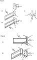
- FIG 3 another embodiment of a telescopic rail according to the invention with a cover is shown in two different views.
- the embodiment is shown in a side view with the cover separated from the tab 2.
- the cover 10 has an attachment portion 14 connected to the cover at two locations. This provides an overall looped coverage.
- This cover 10 can be pushed laterally onto the tab 2 on a first rail element 1 .
- indentations are provided in the fastening section at the points at which the tab 2 is connected to the first rail element 1.
- Figure 3b the embodiment is off Figure 3a ) also shown in a side view, with the cover 10 applied to the flap 2.
- the side 11 of the cover facing the tab rests against the surface 3 of the tab 2 facing the opening of the household appliance, and the fastening section 14 rests against the surface 4 of the tab 2 facing away from the opening of the household appliance, with this surface not being completely separated from the Fixing section covered will.
- Figure 3c shows the in the Figures 3a) and 3b ) illustrated embodiment in a longitudinal section, the section running parallel to the extension direction of the telescopic rail and essentially centrally from top to bottom through the cover 10.
- a further rail element 8 which can be displaced relative to the first rail element 1 .
- the telescopic rail In the state shown, the telescopic rail is not fully pushed together. When the telescopic rail is pushed together completely, the first end 9 of the other rail element 8 strikes the fastening section 14 of the cover 10 .
- the central part of the fastening section 14 therefore serves at the same time as a damping section 18 which prevents the first end 9 of the further rail element 8 from coming into contact with the tab 2 when it is pushed together.
- FIG 4 shows a further embodiment of a telescopic rail according to the invention with a cover in different views.
- Figure 4a shows the embodiment in a side view, with the cover separated from the tab in this view.
- the tab 2 has a special configuration, with an opening 5 being provided.
- a pin 15 is provided on the side 11 of the cover 10 facing the bracket for fastening the cover to the bracket 2 of the first rail element 1 . This is passed through the opening 5 of the tab 2 when the cover is attached, being elastically deformed and compressed as it is passed through.
- Figure 4b shows the embodiment Figure 4a ) also in a side view, with the cover 10 applied to the flap 2.
- the peg After passing the peg 15 through the opening 5, the peg has expanded again due to elastic properties of the material from which the cover and peg are made and provides a secure connection between the cover 10 and the flap 2.
- the pin rests against the surface 4 of the tab 2 facing away from the opening of the household appliance and the cover 10 rests with its surface 11 facing the tab on the surface 3 of the tab 2 pointing towards the opening of the household appliance.
- the cover 10 in this embodiment not only covers the surface 3 completely, but also protrudes beyond it.
- Figure 4c is the embodiment from the Figures 4a) and 4b ) is shown in a longitudinal section, with a further rail element being shown in addition.
- the peg 15 guided through the opening 5 has a mushroom-shaped cross section, which on the one hand allows the peg to be pushed through the opening 5 and on the other hand largely prevents it from being pulled back.
- the pin 15 is also a damping section 18, since when the telescopic rail is pushed together, metal parts of the first and a further rail element do not meet through this pin and in particular the first end 9 of the further rail element 8 comes into contact with the pin.
- projections 13 are provided on the side 12 of the cover 10 facing away from the tab, which projections provide a corrugation.
- FIG 5 shows yet another embodiment of a telescopic rail according to the invention with a cover.
- Figure 5a shows a side plan view, in which the cover 10 is separated from the tab 2 of the first rail element 1.
- the cover 10 On its side 11 facing the tab, the cover 10 has a fastening section 14 which, when the cover 10 is attached to the tab 2, covers a narrow side and a long side of the essentially rectangular tab. Due to this special configuration, the cover 10 can be pushed onto the tab 2 from above.
- the cover also has a web which, when applied to the tab 2 , does not reach behind it and runs along the otherwise free longitudinal side of the tab, thus preventing the cover 10 from slipping off the tab 2 to the side.
- Figure 5b the embodiment is off Figure 5a ) is also shown in a side view, with the cover 10 being slid onto the tab 2.
- Figure 5c represents a sectional view through the tab 2 with the cover, the sectional plane running parallel to the plane in which a baking tray resting on the rail element 1 would run.
- the cover 10 has an asymmetrical fastening section 14 which engages behind the tab 2 on one longitudinal side. On the other longitudinal side there is a web, which however does not engage behind the flap 2 .
- FIG 6 shows a further embodiment of a telescopic rail according to the invention with a cover.
- a tab 2 is attached to the first rail element 1, which is essentially rectangular, but on the narrow sides of which sections are bent away from the rail element.
- FIG. 6a shows a side view of a cover 10 which is applied to a tab 2 on a rail element 1.
- the cover 10 has incisions on its side 11 facing the tab, through which fastening sections 14 are provided. These incisions correspond to the bent-away sections of the lug 2.
- the cover 10 On its side 12 facing away from the lug, the cover 10 has a corrugation formed by projections 13.
- FIG. 13 shows a side view of a cover 10 which is applied to a tab 2 on a rail element 1.
- the cover 10 has incisions on its side 11 facing the tab, through which fastening sections 14 are provided. These incisions correspond to the bent-away sections of the lug 2.
- the cover 10 On its side 12 facing away from the lug, the cover 10 has a corrugation formed by projections 13.
- Figure 6b the embodiment is off Figure 6a ) is shown with cover 10 removed from tab 2.
- FIG. the design of the fastening sections 14 can be clearly seen through incisions in the side of the cover facing the tab.
- figure 7 shows a further embodiment of a telescopic rail according to the invention with a cover. To illustrate the special design of the cover, this is in the Figures 7a) and 7b ) shown without the tab and rail member.
- FIG. 7a the cover is shown in a side view.
- the cover has a fastening section 14 which is connected to the cover at two points, with the cover and fastening section 14 forming a loop which can be pushed laterally onto a tab 2 .
- the cover 10 has on its side facing away from the tab 12 projections 13 in the form of knobs and grooves. This is clearer in the illustration in Figure 6b ) which is a plan view of side 12 of cover 10.
- FIG. 6b is a plan view of side 12 of cover 10.
- FIG 7c is a side view of the in the Figures 7a) and 7b ) shown cover 10 is shown, wherein the cover is applied to a tab 2 on a first rail element 1.
- This figure also shows a further rail element 8 of the telescopic rail, the telescopic rail being shown in a fully collapsed state.
- this depiction also shows a product support 20 which rests on the first rail element 1 .
- the cover extends through the fastening section 14 to the surface 4 of the tab 2 facing away from the opening of the household appliance and has a support section 16 and a holding section 17 there Bearing surface 6 of the first rail element 1 rests and when the food support 20 is applied prevents the food support 20 from directly resting on the rail element 1 .
- the fastening section 14 also prevents the food support from rubbing against the bracket 2 .
- a holding section which runs above the support surface 6 of the first rail element at a distance from the support section 16 which essentially corresponds to the thickness of the food support 20 at this point. This configuration prevents the food support from being unintentionally removed from the telescopic rail.
- the cover 10 extends with its attachment section 14 over a large part of the surface 4 of the tab 2 facing away from the opening of the household appliance Figure 7c ) is shown, the first end 9 of a further rail element 8 rests against the telescopic rail in the fully collapsed state or with which this end comes into contact.
- FIG 8 a further embodiment of a telescopic rail with a cover is shown, the cover 10 being separated from the bracket 2 of the first rail element 1 in order to simplify the illustration.
- the cover has a particularly simple design and provides a side 11 facing the tab, which has a surface which corresponds to the surface of the surface 3 of the tab 2 facing the opening of the household appliance.
- the cover 10 is attached to the flap 2 by gluing.
- FIGS Figure 9 different configurations of the side 12 of covers 10 facing away from the tab are shown.
- the configuration of the surface of this page 12 is independent of the rest of the shape of the cover and the surfaces shown in FIGS Figures 9a), 9b) and 9c ) can be combined as desired with any of the embodiments described above and other embodiments not explicitly described here.
- Figure 9a shows a cover with transverse ribbing, which is formed by rib-shaped projections 13.
- Figure 9b shows a cover with longitudinal projections 13.
- Figure 9c shows a cover with projections 13 in the form of knobs.
Landscapes
- Engineering & Computer Science (AREA)
- Chemical & Material Sciences (AREA)
- Combustion & Propulsion (AREA)
- Mechanical Engineering (AREA)
- General Engineering & Computer Science (AREA)
- Cookers (AREA)
Claims (15)
- Glissière télescopique, avec un premier élément de glissière (1) et au moins un autre élément de glissière, le premier élément de glissière (1) pouvant, dans un état de la glissière télescopique fixé dans un appareil électroménager, être extrait de l'appareil électroménager, et présentant, à son extrémité dirigée vers l'ouverture de l'appareil électroménager, une attache (2) qui s'étend perpendiculairement à la direction de sortie de la glissière télescopique, l'attache (2) présentant au moins sur une face (3) dirigée vers l'ouverture de l'appareil électroménager, un revêtement (10) qui se compose d'un matériau qui est moins bon conducteur de la chaleur que le matériau dont se compose l'attache (2), caractérisée en ce que le revêtement (10) présente un ou plusieurs tronçons de fixation (14) qui s'étend/s'étendent au moins par tronçons sur une face (4) de l'attache (2) éloignée de l'ouverture de l'appareil électroménager.
- Glissière télescopique, avec un premier élément de glissière (1) et au moins un autre élément de glissière, le premier élément de glissière (1) pouvant, dans un état de la glissière télescopique fixé dans un appareil électroménager, être extrait de l'appareil électroménager, et présentant, à son extrémité dirigée vers l'ouverture de l'appareil électroménager, une attache (2) qui s'étend perpendiculairement à la direction de sortie de la glissière télescopique, l'attache (2) présente, au moins sur une face (3) dirigée vers l'ouverture de l'appareil électroménager, un revêtement (10) qui se compose d'un matériau qui est moins bon conducteur de la chaleur que le matériau dont se compose l'attache (2), caractérisée en ce que le revêtement (10) se compose d'un silicone ou comprend un silicone.
- Glissière télescopique, avec un premier élément de glissière (1) et au moins un autre élément de glissière, le premier élément de glissière (1) pouvant, dans un état de la glissière télescopique fixé dans un appareil électroménager, être extrait de l'appareil électroménager, et présentant, à son extrémité dirigée vers l'ouverture de l'appareil électroménager, une attache (2) qui s'étend perpendiculairement à la direction de sortie de la glissière télescopique, l'attache (2) présente, au moins sur une face (3) dirigée vers l'ouverture de l'appareil électroménager, un revêtement (10) qui se compose d'un matériau qui est moins bon conducteur de la chaleur que le matériau dont se compose l'attache (2), caractérisée en ce que le revêtement (10) présente une épaisseur de matériau d'environ 1 mm à environ 3 mm.
- Glissière télescopique selon la revendication 1, 2 ou 3, caractérisée en ce que le revêtement (10) présente une conductivité thermique inférieure à 5 W/(m*K), de préférence inférieure à 3 W/(m*K), de façon particulièrement préférée inférieure à 1 W/(m*K).
- Glissière télescopique selon la revendication 1, 3 ou 4, ou toute revendication dépendante au moins de la revendication 1 ou 3, caractérisée en ce que le revêtement (10) se compose d'un silicone ou comprend un silicone.
- Glissière télescopique selon l'une des revendications précédentes, caractérisée en ce que le revêtement (10) présente un côté (11) tourné vers l'attache et un côté (12) éloigné de l'attache, le revêtement présentant des saillies (13) et/ou des creux sur son côté éloigné de l'attache et/ou sur son côté tourné vers l'attache.
- Glissière télescopique selon l'une des revendications précédentes, caractérisée en ce que, par son côté (11) tourné vers l'attache, le revêtement (10) repose par toute sa surface sur l'attache (2).
- Glissière télescopique selon l'une des revendications précédentes dépendantes au moins de la revendication 1 ou 2, caractérisée en ce que le revêtement (10) présente une épaisseur de matériau d'environ 1 mm à environ 3 mm, de préférence d'environ 1,5 mm à environ 2,5 mm.
- Glissière télescopique selon l'une des revendications 4 à 8 dépendantes au moins de de la revendication 3, caractérisée en ce que le revêtement (10) présente d'environ 1,5 mm à environ 2,5 mm.
- Glissière télescopique selon l'une des revendications précédentes dépendantes au moins de la revendication 2 ou 3, caractérisée en ce que le revêtement (10) présente un ou plusieurs tronçons de fixation (14) qui s'étend/s'étendent au moins par tronçons sur une face (4) de l'attache (2) éloignée de l'ouverture de l'appareil électroménager.
- Glissière télescopique selon l'une des revendications précédentes, caractérisée en ce que le revêtement (10) présente un tronçon d'amortissement (18) qui dépasse au-dessus du plan de la face (4) de l'attache (2) éloignée de l'ouverture de l'appareil électroménager dans une direction éloignée de l'ouverture de l'appareil électroménager, un autre élément de glissière (8) entrant, par une première extrémité (9), en engagement de contact avec le tronçon d'amortissement lors de l'emboîtement complet de la glissière télescopique.
- Glissière télescopique selon l'une des revendications précédentes, caractérisée en ce que, sur son côté (11) tourné vers l'attache, le revêtement (10) présente un tenon (15) qui est guidé à travers une ouverture (5) ménagée dans l'attache, un tronçon du tenon étant adjacent à une face (4) de l'attache éloignée de l'ouverture de l'appareil électroménager.
- Glissière télescopique selon l'une des revendications précédentes, caractérisée en ce que l'attache (2) présente une découpure (7) et en ce que, sur son côté (11) tourné vers l'attache, le revêtement (10) présente un tronçon d'amortissement (18) qui dépasse du revêtement sur une distance supérieure à l'épaisseur de matériau de l'attache et qui est guidé à travers la découpure de l'attache.
- Glissière télescopique selon l'une des revendications précédentes, caractérisée en ce que le premier élément de glissière (1) présente une face d'appui (6) pour l'appui d'un support de produit à cuire, et le revêtement s'étend au moins partiellement sur la face (4) de l'attache éloignée de l'ouverture de l'appareil électroménager, le revêtement présentant, sur le côté de l'attache éloigné de l'ouverture de l'appareil électroménager, un tronçon d'appui (16) reposant sur la face d'appui du premier élément de glissière.
- Glissière télescopique selon l'une des revendications précédentes, caractérisée en ce que le premier élément de glissière (1) présente une face d'appui (6) pour l'appui d'un support de produit à cuire, et le revêtement s'étend au moins partiellement sur la face (4) de l'attache éloignée de l'ouverture de l'appareil électroménager, le revêtement présentant, sur le côté de l'attache éloigné de l'ouverture de l'appareil électroménager, un tronçon de retenue (17) distant de la face d'appui du premier élément de glissière.
Applications Claiming Priority (1)
| Application Number | Priority Date | Filing Date | Title |
|---|---|---|---|
| DE102012106738.4A DE102012106738A1 (de) | 2012-07-24 | 2012-07-24 | Abdeckung |
Publications (3)
| Publication Number | Publication Date |
|---|---|
| EP2690367A1 EP2690367A1 (fr) | 2014-01-29 |
| EP2690367B1 EP2690367B1 (fr) | 2016-09-21 |
| EP2690367B2 true EP2690367B2 (fr) | 2022-04-27 |
Family
ID=48874142
Family Applications (1)
| Application Number | Title | Priority Date | Filing Date |
|---|---|---|---|
| EP13177420.0A Active EP2690367B2 (fr) | 2012-07-24 | 2013-07-22 | Revêtement |
Country Status (2)
| Country | Link |
|---|---|
| EP (1) | EP2690367B2 (fr) |
| DE (1) | DE102012106738A1 (fr) |
Families Citing this family (4)
| Publication number | Priority date | Publication date | Assignee | Title |
|---|---|---|---|---|
| DE102020211463A1 (de) * | 2020-09-11 | 2022-03-17 | BSH Hausgeräte GmbH | Schienenauszugsvorrichtung für ein Mikrowellen-Gargerät mit einem elektrisch isolierenden Abschlusselement an einer Schienenvorderseite, sowie Mikrowellen-Gargerät |
| EP3972387B1 (fr) * | 2020-09-22 | 2025-12-03 | Accuride International GmbH | Rail télescopique |
| DE102022101098A1 (de) | 2022-01-18 | 2023-07-20 | Paul Hettich Gmbh & Co. Kg | Haushaltsgerät und Auszugsführung für ein Haushaltsgerät |
| DE102022101096A1 (de) * | 2022-01-18 | 2023-07-20 | Paul Hettich Gmbh & Co. Kg | Haushaltsgerät und Auszugsführung für ein Haushaltsgerät |
Citations (6)
| Publication number | Priority date | Publication date | Assignee | Title |
|---|---|---|---|---|
| US2186857A (en) † | 1937-08-04 | 1940-01-09 | Robert F Davis | Domestic oven |
| GB2412428A (en) † | 2004-03-25 | 2005-09-28 | David Pike | Oven guard |
| GB2434202A (en) † | 2005-12-21 | 2007-07-18 | Guy Darell Unwin | An oven shelf with a thermally isolating guard |
| US20090064989A1 (en) † | 2007-09-06 | 2009-03-12 | Timothy Scott Shaffer | Oven Rack Apparatus and Corresponding Method |
| US7673628B1 (en) † | 2003-05-01 | 2010-03-09 | JAZ Innovations, LLC | Oven rack guard |
| DE102010016315A1 (de) † | 2010-04-01 | 2011-10-06 | Paul Hettich Gmbh & Co. Kg | Beschlag und Haushaltsgerät |
Family Cites Families (6)
| Publication number | Priority date | Publication date | Assignee | Title |
|---|---|---|---|---|
| DE29803210U1 (de) * | 1998-02-24 | 1998-04-16 | Hettich Paul Gmbh & Co | Auszugsführung |
| DE102005028674A1 (de) * | 2005-06-21 | 2006-12-28 | BSH Bosch und Siemens Hausgeräte GmbH | Teleskopauszugsvorrichtung |
| DE202006009809U1 (de) * | 2006-06-21 | 2007-10-25 | Paul Hettich Gmbh & Co. Kg | Laufschiene einer Auszugsführung |
| DE202008006302U1 (de) * | 2008-05-07 | 2009-09-10 | Paul Hettich & Co Kg | Ausziehführung |
| DE202008014790U1 (de) * | 2008-11-07 | 2010-03-25 | Paul Hettich Gmbh & Co. Kg | Auszugsführung und Backofen |
| DE102009045786A1 (de) * | 2009-10-19 | 2011-05-26 | BSH Bosch und Siemens Hausgeräte GmbH | Vorrichtung zur Aufnahme eines Gargutträgers für ein Hausgerät, Hausgerät, insbesondere Backofen, mit einer derartigen Vorrichtung sowie Verfahren zum Bedienen einer derartigen Vorrichtung |
-
2012
- 2012-07-24 DE DE102012106738.4A patent/DE102012106738A1/de not_active Withdrawn
-
2013
- 2013-07-22 EP EP13177420.0A patent/EP2690367B2/fr active Active
Patent Citations (6)
| Publication number | Priority date | Publication date | Assignee | Title |
|---|---|---|---|---|
| US2186857A (en) † | 1937-08-04 | 1940-01-09 | Robert F Davis | Domestic oven |
| US7673628B1 (en) † | 2003-05-01 | 2010-03-09 | JAZ Innovations, LLC | Oven rack guard |
| GB2412428A (en) † | 2004-03-25 | 2005-09-28 | David Pike | Oven guard |
| GB2434202A (en) † | 2005-12-21 | 2007-07-18 | Guy Darell Unwin | An oven shelf with a thermally isolating guard |
| US20090064989A1 (en) † | 2007-09-06 | 2009-03-12 | Timothy Scott Shaffer | Oven Rack Apparatus and Corresponding Method |
| DE102010016315A1 (de) † | 2010-04-01 | 2011-10-06 | Paul Hettich Gmbh & Co. Kg | Beschlag und Haushaltsgerät |
Also Published As
| Publication number | Publication date |
|---|---|
| DE102012106738A1 (de) | 2014-01-30 |
| EP2690367A1 (fr) | 2014-01-29 |
| EP2690367B1 (fr) | 2016-09-21 |
Similar Documents
| Publication | Publication Date | Title |
|---|---|---|
| EP2690367B2 (fr) | Revêtement | |
| DE102014019997B4 (de) | Gargutträger | |
| DE102013102949A1 (de) | Auszugsführung | |
| DE202008007362U1 (de) | Kühlgutabstellfach | |
| DE102017106104A1 (de) | Auszugsführung und Mikrowellengargerät oder industrieller Wärmeofen mit einer Auszugsführung | |
| DE10333451B4 (de) | Vorrichtung zur Aufnahme von Keramik-Heizelementen und Verfahren zur Herstellung einer solchen | |
| EP2991450B1 (fr) | Système de cuisson | |
| DE102009043770A1 (de) | Aufbewahrungsvorrichtung für Gegenstände in einem Kraftfahrzeug | |
| DE29914007U1 (de) | Tür für ein Gerät, insbesondere einen Garofen, mit unverwechselbar montierbaren Scheiben | |
| EP2436990B1 (fr) | Appareil de cuisson | |
| EP1865135A2 (fr) | Guide pour ferrure de porte coulissante | |
| DE102012005437A1 (de) | Vorrichtung zum Temperieren von in größenmäßig genormten, schalenförmigen rechteckigen Behältern aufgenommenen Speisen | |
| DE202005002549U1 (de) | Gargutträger | |
| EP2314934A2 (fr) | Dispositif de réception d'un plateau de cuisson pour un appareil ménager, appareil ménager, notamment four de cuisson, doté d'un tel dispositif et procédé d'utilisation d'un tel dispositif | |
| WO2023139064A1 (fr) | Appareil ménager et guide coulissant pour appareil ménager | |
| DE102022101096A1 (de) | Haushaltsgerät und Auszugsführung für ein Haushaltsgerät | |
| DE102018128475A1 (de) | Küchengerät | |
| DE102010008484A1 (de) | Tellerhalter für Tellerhordengestell | |
| DE102017111608A1 (de) | Küchengerät | |
| WO2018153688A1 (fr) | Appareil de cuisson pourvu d'un support d'accessoire | |
| DE102012201759A1 (de) | Backofentürdichtungssystem, Haushaltsgerät und Verfahren zum Befestigen einer Dichtung | |
| EP2910857A1 (fr) | Appareil ménager doté d'un élément avant à poignée intégrée | |
| DE10114098A1 (de) | Backofen | |
| DE102008041044A1 (de) | Gargerät | |
| DE3443544A1 (de) | Toaster-aufsatz |
Legal Events
| Date | Code | Title | Description |
|---|---|---|---|
| PUAI | Public reference made under article 153(3) epc to a published international application that has entered the european phase |
Free format text: ORIGINAL CODE: 0009012 |
|
| AK | Designated contracting states |
Kind code of ref document: A1 Designated state(s): AL AT BE BG CH CY CZ DE DK EE ES FI FR GB GR HR HU IE IS IT LI LT LU LV MC MK MT NL NO PL PT RO RS SE SI SK SM TR |
|
| AX | Request for extension of the european patent |
Extension state: BA ME |
|
| 17P | Request for examination filed |
Effective date: 20140723 |
|
| RBV | Designated contracting states (corrected) |
Designated state(s): AL AT BE BG CH CY CZ DE DK EE ES FI FR GB GR HR HU IE IS IT LI LT LU LV MC MK MT NL NO PL PT RO RS SE SI SK SM TR |
|
| GRAP | Despatch of communication of intention to grant a patent |
Free format text: ORIGINAL CODE: EPIDOSNIGR1 |
|
| RIC1 | Information provided on ipc code assigned before grant |
Ipc: F24C 15/16 20060101AFI20160323BHEP |
|
| INTG | Intention to grant announced |
Effective date: 20160426 |
|
| GRAS | Grant fee paid |
Free format text: ORIGINAL CODE: EPIDOSNIGR3 |
|
| GRAA | (expected) grant |
Free format text: ORIGINAL CODE: 0009210 |
|
| AK | Designated contracting states |
Kind code of ref document: B1 Designated state(s): AL AT BE BG CH CY CZ DE DK EE ES FI FR GB GR HR HU IE IS IT LI LT LU LV MC MK MT NL NO PL PT RO RS SE SI SK SM TR |
|
| REG | Reference to a national code |
Ref country code: GB Ref legal event code: FG4D Free format text: NOT ENGLISH |
|
| REG | Reference to a national code |
Ref country code: CH Ref legal event code: EP |
|
| REG | Reference to a national code |
Ref country code: AT Ref legal event code: REF Ref document number: 831367 Country of ref document: AT Kind code of ref document: T Effective date: 20161015 |
|
| REG | Reference to a national code |
Ref country code: IE Ref legal event code: FG4D Free format text: LANGUAGE OF EP DOCUMENT: GERMAN |
|
| REG | Reference to a national code |
Ref country code: DE Ref legal event code: R096 Ref document number: 502013004653 Country of ref document: DE |
|
| REG | Reference to a national code |
Ref country code: LT Ref legal event code: MG4D Ref country code: NL Ref legal event code: MP Effective date: 20160921 |
|
| PG25 | Lapsed in a contracting state [announced via postgrant information from national office to epo] |
Ref country code: NO Free format text: LAPSE BECAUSE OF FAILURE TO SUBMIT A TRANSLATION OF THE DESCRIPTION OR TO PAY THE FEE WITHIN THE PRESCRIBED TIME-LIMIT Effective date: 20161221 Ref country code: RS Free format text: LAPSE BECAUSE OF FAILURE TO SUBMIT A TRANSLATION OF THE DESCRIPTION OR TO PAY THE FEE WITHIN THE PRESCRIBED TIME-LIMIT Effective date: 20160921 Ref country code: FI Free format text: LAPSE BECAUSE OF FAILURE TO SUBMIT A TRANSLATION OF THE DESCRIPTION OR TO PAY THE FEE WITHIN THE PRESCRIBED TIME-LIMIT Effective date: 20160921 Ref country code: LT Free format text: LAPSE BECAUSE OF FAILURE TO SUBMIT A TRANSLATION OF THE DESCRIPTION OR TO PAY THE FEE WITHIN THE PRESCRIBED TIME-LIMIT Effective date: 20160921 |
|
| PG25 | Lapsed in a contracting state [announced via postgrant information from national office to epo] |
Ref country code: GR Free format text: LAPSE BECAUSE OF FAILURE TO SUBMIT A TRANSLATION OF THE DESCRIPTION OR TO PAY THE FEE WITHIN THE PRESCRIBED TIME-LIMIT Effective date: 20161222 Ref country code: SE Free format text: LAPSE BECAUSE OF FAILURE TO SUBMIT A TRANSLATION OF THE DESCRIPTION OR TO PAY THE FEE WITHIN THE PRESCRIBED TIME-LIMIT Effective date: 20160921 Ref country code: LV Free format text: LAPSE BECAUSE OF FAILURE TO SUBMIT A TRANSLATION OF THE DESCRIPTION OR TO PAY THE FEE WITHIN THE PRESCRIBED TIME-LIMIT Effective date: 20160921 Ref country code: NL Free format text: LAPSE BECAUSE OF FAILURE TO SUBMIT A TRANSLATION OF THE DESCRIPTION OR TO PAY THE FEE WITHIN THE PRESCRIBED TIME-LIMIT Effective date: 20160921 |
|
| PG25 | Lapsed in a contracting state [announced via postgrant information from national office to epo] |
Ref country code: RO Free format text: LAPSE BECAUSE OF FAILURE TO SUBMIT A TRANSLATION OF THE DESCRIPTION OR TO PAY THE FEE WITHIN THE PRESCRIBED TIME-LIMIT Effective date: 20160921 Ref country code: EE Free format text: LAPSE BECAUSE OF FAILURE TO SUBMIT A TRANSLATION OF THE DESCRIPTION OR TO PAY THE FEE WITHIN THE PRESCRIBED TIME-LIMIT Effective date: 20160921 |
|
| PG25 | Lapsed in a contracting state [announced via postgrant information from national office to epo] |
Ref country code: IS Free format text: LAPSE BECAUSE OF FAILURE TO SUBMIT A TRANSLATION OF THE DESCRIPTION OR TO PAY THE FEE WITHIN THE PRESCRIBED TIME-LIMIT Effective date: 20170121 Ref country code: SM Free format text: LAPSE BECAUSE OF FAILURE TO SUBMIT A TRANSLATION OF THE DESCRIPTION OR TO PAY THE FEE WITHIN THE PRESCRIBED TIME-LIMIT Effective date: 20160921 Ref country code: PL Free format text: LAPSE BECAUSE OF FAILURE TO SUBMIT A TRANSLATION OF THE DESCRIPTION OR TO PAY THE FEE WITHIN THE PRESCRIBED TIME-LIMIT Effective date: 20160921 Ref country code: PT Free format text: LAPSE BECAUSE OF FAILURE TO SUBMIT A TRANSLATION OF THE DESCRIPTION OR TO PAY THE FEE WITHIN THE PRESCRIBED TIME-LIMIT Effective date: 20170123 Ref country code: CZ Free format text: LAPSE BECAUSE OF FAILURE TO SUBMIT A TRANSLATION OF THE DESCRIPTION OR TO PAY THE FEE WITHIN THE PRESCRIBED TIME-LIMIT Effective date: 20160921 Ref country code: SK Free format text: LAPSE BECAUSE OF FAILURE TO SUBMIT A TRANSLATION OF THE DESCRIPTION OR TO PAY THE FEE WITHIN THE PRESCRIBED TIME-LIMIT Effective date: 20160921 Ref country code: ES Free format text: LAPSE BECAUSE OF FAILURE TO SUBMIT A TRANSLATION OF THE DESCRIPTION OR TO PAY THE FEE WITHIN THE PRESCRIBED TIME-LIMIT Effective date: 20160921 Ref country code: BG Free format text: LAPSE BECAUSE OF FAILURE TO SUBMIT A TRANSLATION OF THE DESCRIPTION OR TO PAY THE FEE WITHIN THE PRESCRIBED TIME-LIMIT Effective date: 20161221 |
|
| REG | Reference to a national code |
Ref country code: DE Ref legal event code: R026 Ref document number: 502013004653 Country of ref document: DE |
|
| PLBI | Opposition filed |
Free format text: ORIGINAL CODE: 0009260 |
|
| 26 | Opposition filed |
Opponent name: PAUL HETTICH GMBH & CO. KG Effective date: 20170620 |
|
| PLAX | Notice of opposition and request to file observation + time limit sent |
Free format text: ORIGINAL CODE: EPIDOSNOBS2 |
|
| PG25 | Lapsed in a contracting state [announced via postgrant information from national office to epo] |
Ref country code: DK Free format text: LAPSE BECAUSE OF FAILURE TO SUBMIT A TRANSLATION OF THE DESCRIPTION OR TO PAY THE FEE WITHIN THE PRESCRIBED TIME-LIMIT Effective date: 20160921 |
|
| PG25 | Lapsed in a contracting state [announced via postgrant information from national office to epo] |
Ref country code: SI Free format text: LAPSE BECAUSE OF FAILURE TO SUBMIT A TRANSLATION OF THE DESCRIPTION OR TO PAY THE FEE WITHIN THE PRESCRIBED TIME-LIMIT Effective date: 20160921 |
|
| PLBB | Reply of patent proprietor to notice(s) of opposition received |
Free format text: ORIGINAL CODE: EPIDOSNOBS3 |
|
| REG | Reference to a national code |
Ref country code: CH Ref legal event code: PL |
|
| REG | Reference to a national code |
Ref country code: IE Ref legal event code: MM4A |
|
| REG | Reference to a national code |
Ref country code: FR Ref legal event code: ST Effective date: 20180330 |
|
| PG25 | Lapsed in a contracting state [announced via postgrant information from national office to epo] |
Ref country code: CH Free format text: LAPSE BECAUSE OF NON-PAYMENT OF DUE FEES Effective date: 20170731 Ref country code: LI Free format text: LAPSE BECAUSE OF NON-PAYMENT OF DUE FEES Effective date: 20170731 Ref country code: IE Free format text: LAPSE BECAUSE OF NON-PAYMENT OF DUE FEES Effective date: 20170722 |
|
| PG25 | Lapsed in a contracting state [announced via postgrant information from national office to epo] |
Ref country code: FR Free format text: LAPSE BECAUSE OF NON-PAYMENT OF DUE FEES Effective date: 20170731 |
|
| REG | Reference to a national code |
Ref country code: BE Ref legal event code: MM Effective date: 20170731 |
|
| PG25 | Lapsed in a contracting state [announced via postgrant information from national office to epo] |
Ref country code: LU Free format text: LAPSE BECAUSE OF NON-PAYMENT OF DUE FEES Effective date: 20170722 |
|
| PG25 | Lapsed in a contracting state [announced via postgrant information from national office to epo] |
Ref country code: BE Free format text: LAPSE BECAUSE OF NON-PAYMENT OF DUE FEES Effective date: 20170731 |
|
| PG25 | Lapsed in a contracting state [announced via postgrant information from national office to epo] |
Ref country code: MT Free format text: LAPSE BECAUSE OF FAILURE TO SUBMIT A TRANSLATION OF THE DESCRIPTION OR TO PAY THE FEE WITHIN THE PRESCRIBED TIME-LIMIT Effective date: 20160921 |
|
| PG25 | Lapsed in a contracting state [announced via postgrant information from national office to epo] |
Ref country code: AL Free format text: LAPSE BECAUSE OF FAILURE TO SUBMIT A TRANSLATION OF THE DESCRIPTION OR TO PAY THE FEE WITHIN THE PRESCRIBED TIME-LIMIT Effective date: 20160921 |
|
| APBM | Appeal reference recorded |
Free format text: ORIGINAL CODE: EPIDOSNREFNO |
|
| APBP | Date of receipt of notice of appeal recorded |
Free format text: ORIGINAL CODE: EPIDOSNNOA2O |
|
| APAH | Appeal reference modified |
Free format text: ORIGINAL CODE: EPIDOSCREFNO |
|
| APBQ | Date of receipt of statement of grounds of appeal recorded |
Free format text: ORIGINAL CODE: EPIDOSNNOA3O |
|
| PG25 | Lapsed in a contracting state [announced via postgrant information from national office to epo] |
Ref country code: MC Free format text: LAPSE BECAUSE OF FAILURE TO SUBMIT A TRANSLATION OF THE DESCRIPTION OR TO PAY THE FEE WITHIN THE PRESCRIBED TIME-LIMIT Effective date: 20160921 Ref country code: HU Free format text: LAPSE BECAUSE OF FAILURE TO SUBMIT A TRANSLATION OF THE DESCRIPTION OR TO PAY THE FEE WITHIN THE PRESCRIBED TIME-LIMIT; INVALID AB INITIO Effective date: 20130722 |
|
| REG | Reference to a national code |
Ref country code: AT Ref legal event code: MM01 Ref document number: 831367 Country of ref document: AT Kind code of ref document: T Effective date: 20180722 |
|
| PG25 | Lapsed in a contracting state [announced via postgrant information from national office to epo] |
Ref country code: CY Free format text: LAPSE BECAUSE OF NON-PAYMENT OF DUE FEES Effective date: 20160921 |
|
| PG25 | Lapsed in a contracting state [announced via postgrant information from national office to epo] |
Ref country code: MK Free format text: LAPSE BECAUSE OF FAILURE TO SUBMIT A TRANSLATION OF THE DESCRIPTION OR TO PAY THE FEE WITHIN THE PRESCRIBED TIME-LIMIT Effective date: 20160921 |
|
| PG25 | Lapsed in a contracting state [announced via postgrant information from national office to epo] |
Ref country code: AT Free format text: LAPSE BECAUSE OF NON-PAYMENT OF DUE FEES Effective date: 20180722 |
|
| PG25 | Lapsed in a contracting state [announced via postgrant information from national office to epo] |
Ref country code: TR Free format text: LAPSE BECAUSE OF FAILURE TO SUBMIT A TRANSLATION OF THE DESCRIPTION OR TO PAY THE FEE WITHIN THE PRESCRIBED TIME-LIMIT Effective date: 20160921 |
|
| PG25 | Lapsed in a contracting state [announced via postgrant information from national office to epo] |
Ref country code: HR Free format text: LAPSE BECAUSE OF FAILURE TO SUBMIT A TRANSLATION OF THE DESCRIPTION OR TO PAY THE FEE WITHIN THE PRESCRIBED TIME-LIMIT Effective date: 20160921 |
|
| APBU | Appeal procedure closed |
Free format text: ORIGINAL CODE: EPIDOSNNOA9O |
|
| PUAH | Patent maintained in amended form |
Free format text: ORIGINAL CODE: 0009272 |
|
| STAA | Information on the status of an ep patent application or granted ep patent |
Free format text: STATUS: PATENT MAINTAINED AS AMENDED |
|
| 27A | Patent maintained in amended form |
Effective date: 20220427 |
|
| AK | Designated contracting states |
Kind code of ref document: B2 Designated state(s): AL AT BE BG CH CY CZ DE DK EE ES FI FR GB GR HR HU IE IS IT LI LT LU LV MC MK MT NL NO PL PT RO RS SE SI SK SM TR |
|
| REG | Reference to a national code |
Ref country code: DE Ref legal event code: R102 Ref document number: 502013004653 Country of ref document: DE |
|
| PGFP | Annual fee paid to national office [announced via postgrant information from national office to epo] |
Ref country code: DE Payment date: 20250717 Year of fee payment: 13 |
|
| PGFP | Annual fee paid to national office [announced via postgrant information from national office to epo] |
Ref country code: IT Payment date: 20250724 Year of fee payment: 13 |
|
| PGFP | Annual fee paid to national office [announced via postgrant information from national office to epo] |
Ref country code: GB Payment date: 20250722 Year of fee payment: 13 |