EP2690316A2 - Anfahrelement mit hydrodynamischen Drehmomentwandler - Google Patents
Anfahrelement mit hydrodynamischen Drehmomentwandler Download PDFInfo
- Publication number
- EP2690316A2 EP2690316A2 EP13173582.1A EP13173582A EP2690316A2 EP 2690316 A2 EP2690316 A2 EP 2690316A2 EP 13173582 A EP13173582 A EP 13173582A EP 2690316 A2 EP2690316 A2 EP 2690316A2
- Authority
- EP
- European Patent Office
- Prior art keywords
- starting element
- axial
- vibration damper
- axial direction
- turbine
- Prior art date
- Legal status (The legal status is an assumption and is not a legal conclusion. Google has not performed a legal analysis and makes no representation as to the accuracy of the status listed.)
- Granted
Links
Images

Classifications
-
- F—MECHANICAL ENGINEERING; LIGHTING; HEATING; WEAPONS; BLASTING
- F16—ENGINEERING ELEMENTS AND UNITS; GENERAL MEASURES FOR PRODUCING AND MAINTAINING EFFECTIVE FUNCTIONING OF MACHINES OR INSTALLATIONS; THERMAL INSULATION IN GENERAL
- F16H—GEARING
- F16H45/00—Combinations of fluid gearings for conveying rotary motion with couplings or clutches
- F16H45/02—Combinations of fluid gearings for conveying rotary motion with couplings or clutches with mechanical clutches for bridging a fluid gearing of the hydrokinetic type
-
- F—MECHANICAL ENGINEERING; LIGHTING; HEATING; WEAPONS; BLASTING
- F16—ENGINEERING ELEMENTS AND UNITS; GENERAL MEASURES FOR PRODUCING AND MAINTAINING EFFECTIVE FUNCTIONING OF MACHINES OR INSTALLATIONS; THERMAL INSULATION IN GENERAL
- F16H—GEARING
- F16H41/00—Rotary fluid gearing of the hydrokinetic type
- F16H41/24—Details
- F16H2041/246—Details relating to one way clutch of the stator
-
- F—MECHANICAL ENGINEERING; LIGHTING; HEATING; WEAPONS; BLASTING
- F16—ENGINEERING ELEMENTS AND UNITS; GENERAL MEASURES FOR PRODUCING AND MAINTAINING EFFECTIVE FUNCTIONING OF MACHINES OR INSTALLATIONS; THERMAL INSULATION IN GENERAL
- F16H—GEARING
- F16H45/00—Combinations of fluid gearings for conveying rotary motion with couplings or clutches
- F16H45/02—Combinations of fluid gearings for conveying rotary motion with couplings or clutches with mechanical clutches for bridging a fluid gearing of the hydrokinetic type
- F16H2045/0221—Combinations of fluid gearings for conveying rotary motion with couplings or clutches with mechanical clutches for bridging a fluid gearing of the hydrokinetic type with damping means
- F16H2045/0226—Combinations of fluid gearings for conveying rotary motion with couplings or clutches with mechanical clutches for bridging a fluid gearing of the hydrokinetic type with damping means comprising two or more vibration dampers
-
- F—MECHANICAL ENGINEERING; LIGHTING; HEATING; WEAPONS; BLASTING
- F16—ENGINEERING ELEMENTS AND UNITS; GENERAL MEASURES FOR PRODUCING AND MAINTAINING EFFECTIVE FUNCTIONING OF MACHINES OR INSTALLATIONS; THERMAL INSULATION IN GENERAL
- F16H—GEARING
- F16H45/00—Combinations of fluid gearings for conveying rotary motion with couplings or clutches
- F16H45/02—Combinations of fluid gearings for conveying rotary motion with couplings or clutches with mechanical clutches for bridging a fluid gearing of the hydrokinetic type
- F16H2045/0221—Combinations of fluid gearings for conveying rotary motion with couplings or clutches with mechanical clutches for bridging a fluid gearing of the hydrokinetic type with damping means
- F16H2045/0263—Combinations of fluid gearings for conveying rotary motion with couplings or clutches with mechanical clutches for bridging a fluid gearing of the hydrokinetic type with damping means the damper comprising a pendulum
-
- F—MECHANICAL ENGINEERING; LIGHTING; HEATING; WEAPONS; BLASTING
- F16—ENGINEERING ELEMENTS AND UNITS; GENERAL MEASURES FOR PRODUCING AND MAINTAINING EFFECTIVE FUNCTIONING OF MACHINES OR INSTALLATIONS; THERMAL INSULATION IN GENERAL
- F16H—GEARING
- F16H45/00—Combinations of fluid gearings for conveying rotary motion with couplings or clutches
- F16H45/02—Combinations of fluid gearings for conveying rotary motion with couplings or clutches with mechanical clutches for bridging a fluid gearing of the hydrokinetic type
- F16H2045/0273—Combinations of fluid gearings for conveying rotary motion with couplings or clutches with mechanical clutches for bridging a fluid gearing of the hydrokinetic type characterised by the type of the friction surface of the lock-up clutch
- F16H2045/0284—Multiple disk type lock-up clutch
Definitions
- Embodiments of the present invention are concerned with Anfemmenfementen or starting transducers, in particular with a comprehensive hydrodynamic torque converter starting element.
- Starting elements for transmitting a torque from a drive unit to a downstream drive train, for example to a transmission are known in a variety of designs.
- Hydrodynamic converters or hydrodynamic torque converters are often used to enable automatic starting in order to increase the energy efficiency after starting in so-called lock-up operation of lockup clutches in order to prevent flow losses and to optimize the consumption of fuel or drive energy.
- Such start-up elements or starting transducers are often combined with so-called torsional vibration dampers, which may be designed in one or more stages, and which have a drive-side input component which can be connected in a rotationally fixed manner to a rotating drive unit.
- the drive-side component a component or an assembly which is located in relation to the power flow from the driving unit towards the end of the drive train closer to the driving unit than a designated as the output side component.
- vibration absorber To further increase the ride comfort and to further suppress vibrations in the drive train with bridged converter beyond so-called vibration absorber are installed.
- vibration absorbers or absorbers When vibration absorbers or absorbers are, generally speaking, to additional masses, via a spring system the drive system or the torsional vibration damper are coupled.
- the mode of action of a vibration damper is based, for example, on the fact that an oscillatory system, which consists of a main mass and an additional mass, is tuned with respect to its natural frequency such that at a certain excitation frequency the additional mass, also referred to as the absorber weight, performs a forced oscillation, while the main mass remains at rest, so that such vibration frequencies can be efficiently suppressed.
- a vibration damper is hereby understood to mean an apparatus or arrangement of components by means of which no torque is transmitted, and which is able to extract energy from the drive train at a certain, possibly variable oscillation frequency in order to occur at this frequency To suppress torsional vibrations.
- a major challenge is to arrange such a large number of components or assemblies in a starting element efficiently and space-saving.
- Embodiments of the present invention make it possible by using a hydrodynamic torque converter in a starting element for transmitting a torque from a drive-side rotation input of the starting element to an output hub, in which a first axial position of an edge of a turbine shell which delimits a turbine wheel against an axial direction assumes a predetermined position with respect to a second axial position defined by the center of a freewheel, by means of which a stator of the hydrodynamic torque converter is rotatably mounted in one direction.
- the difference between the first axial position and the second axial position is greater than a predetermined minimum value.
- the turbine wheel is offset in the axial direction such that its limit counter to the axial direction is approximately at the axial position of the center of the stator idler.
- the turbine wheel can be offset in the axial direction in the direction of the freewheel of the stator so that in a direction perpendicular to the axial direction radial direction outside a Turbinenradflansches, by means of which the turbine wheel with the output hub of the starting element is rotatably connected, additional Space is created to arrange more mechanical components. This may allow a compact, containing a plurality of assemblies arrangement for a starting element.
- a predetermined minimum value for the difference of the two axial positions is 0 mm, so that the first axial position of the boundary of the turbine wheel lies after the second axial position of the center of the freewheel, i. h.,
- the entire hydrodynamically active arrangement of the hydrodynamic torque converter, consisting of turbine wheel, stator and impeller, is so far offset in the axial direction with respect to the freewheel that they are completely behind the center of the freewheel to additional axial functionality without affecting the functionality To create space for possible other modules in the starting element.
- the predetermined minimum value is -5 mm, d. h.,
- the hydrodynamically effective arrangement of turbine wheel, stator and impeller is largely axially offset behind the freewheel.
- Embodiments of the invention may thus, inter alia, make it possible to introduce additional components into an existing starting gear or into an existing converter, for example for a motor vehicle, without having to change the position of already existing gears between the stator and the stator support shaft or between the output hub for the transmission input shaft.
- the stator in order to effect an axial offset, is connected to the freewheel with a freewheel extending from the freewheel in the radial direction to the stator, wherein the stator has a conical portion whose lateral surface with the on the axial Direction vertical radial direction forms an angle in the range between 28 ° and 63 °. That is, the axial offset is made possible, inter alia, by a flange of a cone-shaped basic geometry that is inclined relative to the radial direction. Depending on the circumstances, in alternative embodiments, this angle can also lie within an interval of 35 ° to 63 ° or 45 ° to 63 °.
- a turbine wheel flange by means of which the turbine wheel is non-rotatably connected to the output hub via a first mechanical connection, also extends in a conical region at least partially parallel to the conical region of the stator flange. In some embodiments, this can lead to improved flow guidance of the hydraulic oil circulating in the hydrodynamic torque converter or the hydraulic fluid used.
- the hydrodynamic torque converter is compressed in the axial direction, i. That is, an aspect ratio A between an axial extent of the hydrodynamic torque converter and a radial extent of the turbine wheel is in a range between 0.55 and 0.8, resulting in an approximately ovalized overall structure.
- the axial extent of the hydrodynamic torque converter is to be understood as that extent which exists between the turbine shell which delimits the torque converter from the axial direction and the pump shell which delimits the hydrodynamic torque converter in the axial direction. That is, in some embodiments, in addition to the axial offset, a hydrodynamically active circuit may be used that is radially more expanded than axially to additionally provide additional space in the axial direction without compromising overall functionality.
- the aspect ratio A may also be in a range of 0.6 to 0.8 or in a range of 0.65 to 0.8.
- the additionally obtained axial packaging space is used to connect a vibration damper between a torsional vibration damper, which adjoins the hydrodynamic torque converter in the axial direction, and the hydrodynamic torque converter itself to arrange to improve the vibration damping properties of the starting element, without requiring significantly more space in the axial direction.
- the utilization of the additional axial space can be additionally favored if a second mechanical connection, by means of which the vibration damper is rotatably connected to the torsional vibration damper, radially outside of a first mechanical connection, by means of which the Turbinenradflansch is rotatably connected to the output hub.
- some embodiments of the invention may make it possible to cope with increased demands of vehicle manufacturers in terms of comfort and performance without requiring significant modifications to the overall landing gear, since an embodiment of a starting element according to the invention can be made with the same external dimensions as heretofore.
- the output hub 8 rotates about a rotation axis 10, along which the substantially rotationally symmetrical starting element extends in an axial direction 12 parallel to the rotation axis 10.
- the motor-side converter cover 14 is welded to a transmission-side or output-side housing part, the pump shell 18 having at its axial end as part of the hydrodynamic torque converter 4 impeller blades 20, by means of which a hydraulically active liquid is conveyed in the direction of turbine blades 22 of the hydrodynamic converter, when the housing is rotated about the flexible plates 16.
- the hydrodynamic torque converter further comprises a stator 24, by means of which the hydraulic circuit between the impeller blades 20 and the turbine blades 22 is closed.
- the stator 24 is connected via a Leitradflansch 58 with a freewheel 52.
- a freewheel 52 is an assembly of components or components that allows rotation in one direction of rotation and stops in the opposite direction of rotation.
- the turbine wheel In order to transmit the rotation of the turbine blades 22, the turbine wheel is connected in a rotationally fixed manner to the output hub 8 via a turbine wheel flange 26. More specifically, the output hub 8 has a mounting flange 30 extending therefrom in a radial direction 28 perpendicular to the axial direction 12 and rotatably connected to the turbine wheel flange 26 of the turbine wheel via a first mechanical connection 32 in the form of rivets.
- annular thrust washer 34 is arranged on the mounting flange 30 in the axial direction 12 opposite side of the Turbinenradflansches 26, by means of which against the axial Direction 12, a force is exerted on the Turbinenradflansch 26 and extending against the radial direction 28 to the output hub 8 to support the output hub 8 and increase the stability of the connection between the Turbinenradflansch 26 and the mounting flange 30 of the output hub 8.
- the thrust washer 34 extends inwardly against the radial direction to the output hub 8, which radially centers and fixes the thrust washer.
- the back, that is, the axial end of the thrust washer 34 is in the in Fig. 1 shown embodiment designed as a raceway for a rolling bearing on which the hub of the stator 24 is supported against the axial direction 12, so that over the roller bearing and the thrust washer 34 against the axial direction, the force used for clamping the Turbinenradflansches 26 is exerted.
- the axial bearing or of the roller bearing and a plain bearing can be used.
- the individual rolling elements can be made either of steel or a resistant plastic.
- the thrust washer 34 may be made of a plastic.
- the thrust washer at its axial end, for example, grooves or recesses for guiding or channeling of oil.
- the torque and the rotation is transmitted by means of two spring elements 40a and 40b from the input part to an output part 42 of the torque converter, which is connected by means of the first mechanical connection 32 with the mounting flange 30 of the output hub 8 to produce the output-side adhesion.
- the vibration damper 6 is non-rotatably coupled via a second mechanical connection 44 to the torsional vibration damper 2.
- the second mechanical connection 44 is located radially further outward than the first mechanical connection 32, which corresponds to the in Fig. 1 shown extremely compact arrangement of the vibration absorber 6 between the torsional vibration damper 2 and the turbine allows.
- the vibration damper 6 is riveted to the torsional vibration damper 2 via a Tilgeritatielement 46 extending radially from the radially inward to the output hub 8. That is, the first and second mechanical joints 32 and 44 are in the in Fig. 1 each embodiment shown executed as riveting. Of course, in alternative embodiments, each connection may be made by any other type of mechanical attachment.
- Tilgeritatiefement 46 one or more absorber weights are attached, which allow the functionality of the vibration absorber 6.
- the Tilgeryelement 46 mounted on its center holes on the outer diameter of the output hub 8, which, even with the use of large absorber weights, unfavorable arrangement of other bearings or play in the camps used can prevent imbalances.
- the torsional vibration damper 2 which is coupled via the second mechanical connection 44 with the Tilgeritatielement 46, based on the Tilgeritatielement 46 in the radial direction 28 inwardly on the output hub 8 from, so that a large support distance is formed. This can effectively prevent the possible tilting of absorber 6 and torsional vibration damper 2 relative to the output hub 8.
- the torsional vibration damper 2 is supported radially on the output hub 8 radially. That is, in such an embodiment, one of the rotating components, that is, the output member 42, the input member, or an intermediate plate between the elastic members 40a and 40b would extend inward in the radial direction to the surface of the output hub 8 to provide support ,
- a cover plate 48 of the torsional vibration damper 2 extends counter to the radial direction to the inside, that this with a contact surface 50 on the output hub 8, which partially parallel to the cover plate 48th extends, overlaps in the radial direction 28, so that by the stop surface 50, a movement of the torsional vibration damper 2 in or against the axial direction is inhibited or prevented.
- This may serve to prevent the efforts due to introduced axial forces on the cover plates of the torsional vibration damper 2 efforts that the torsional vibration damper 2 shifts in the axial direction 12 to prevent.
- the movement of the torsional vibration damper 2 in the axial direction 12 is inhibited by the abutment surface 50 on the output hub 8, whereas the movement against the axial direction 12 is restricted or inhibited via a bushing rotatably connected to the output hub 8 or via the cover hub ,
- the bearing between the thrust surfaces 50 and the cover plate 48 is subject to play, so that there may be no increased friction.
- an axial support can also take place via the intermediate plate of the torsional vibration damper 2, whose relative movements with respect to the output hub 8 are smaller, so that a possible wear can be further prevented.
- the counter to the axial direction 12 movement-inhibiting acting bushing can be rotatably connected to the output hub 8 or the converter cover 14. Due to the axial contact between the bushing and the output hub 8, axial forces are transmitted directly beyond, without being able to exert negative influences on the torsional vibration damper 2.
- friction devices for damping vibrations can be integrated, which can be arranged inter alia between the left cover plate 48 and the output hub 8.
- Alternative arrangements of such friction devices can be arranged, for example, between the left cover plate 48 and the output component 42 of the torsional vibration damper 2, or between the head piece and the left cover plate 48.
- the hydrodynamic torque converter 4 is offset according to the embodiments of the invention in the axial direction 12 with respect to the center of the freewheel 52.
- the center of the freewheel is to be understood here as the second axial position 54 in the axial direction 12, which determines the center with respect to the freewheel 52 forming components in the axial direction 12, for example, the axis of symmetry of a freewheel or the like.
- a difference X with respect to a first axial position 53 (X1) passing through the end of the turbine wheel opposite to the axial direction of the limiting turbine shell 56 56 is determined, and the second axial position 54 (X2) is in the in the FIGS. 1 and 2 That is, the hydrodynamically active circuit of the hydrodynamic torque converter 4 is located in the axial direction 12 completely behind the center of the freewheel 52nd
- the coordinate values of the axial positions are determined so that the coordinate values in the axial direction increase.
- the axial positions in this case refer to a reference point, which is given by the position of the flexible plates 16 for introducing the torque in the starting element.
- the axial position may also be determined with respect to another origin.
- the stator 24 is connected via a Leitradflansch 58 to the freewheel 52, wherein the Leitradflansch 58 has a conical portion to effect the displacement of the stator 24 with respect to the freewheel 52.
- the conical region more precisely a lateral surface of the cone forming the conical region, encloses with the radial direction 28 an angle 60 which can be chosen according to the desired axial offset and which preferably lies between 28 ° and 63 °.
- the turbine wheel consisting of the annular turbine shell 56 and the turbine blades 22 mounted therein, is non-rotatably connected to the output hub 8 by means of a turbine wheel flange 26 integrally formed with the turbine shell 56.
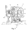
- the turbine wheel flange 26 and the turbine shell 56 may also consist of two separate components, such as in FIG Fig. 2 is illustrated. Such a two-part design can facilitate production of the then separate components more easily and with higher accuracy.
- the different components, ie, the turbine shell 56 and the turbine wheel flange 26 may be made of different materials to better accommodate the different requirements of the individual components, such that overall weight may be saved, for example. Especially Both components can be dimensioned independently of one another, for example with regard to their material thickness.
- connection between Turbinenradflansch 26 and turbine shell 56 can be produced in any way force, positive or cohesive.
- the connection may also be made by penetration of the turbine blades 22 through the turbine shell 56 with the sweeping portions of the turbine blades 22 being flipped or rolled to provide a rotationally fixed connection between the turbine shell 56 and the turbine wheel flange 26.
- a first or second mechanical connection in the sense described above can be any positive, non-positive or integral connection.
- Positive locking in this context means that a connection which prevents a relative movement of the interconnected components in at least one connection direction is effected by the geometry of the components used for connection being selected such that they overlap in a direction perpendicular to the connection direction, so as to prevent the movement in the connecting direction.
- Frictionally means in this context that a compound which prevents relative movement of the interconnected components in at least one direction, by a force acting between the components perpendicular to the connection direction force, for example, leads to increased cohesive or adhesive forces, is effected. A traction is thus present as long as a force caused by the static friction between the components is not exceeded.
- Cohesive means in this context that a compound that prevents relative movement of the interconnected components in at least one direction, is mediated by atomic or molecular forces.
- a mixing of the materials of the connected components take place at an interface. This need not be solely between the materials of the connected components alone. Rather, in addition, a mixing causing or supporting material component, for example in the form of an adhesive or a material of a welding wire may be present, so at the interface a plurality of materials are mixed together on a microscopic scale.
- the aspect ratio A thus describes the ratio between the axial extent of the hydrodynamic torque converter 4 and the radial extent of the same.
- the radial extent is determined, for example, by the radial extent of the turbine shell 56, whereas the axial extent corresponds to the maximum axial extent of the hydrodynamic torque converter 4 between the turbine shell 56 and the pump shell 18 bounding the impeller in the axial direction.
- Fig. 1 shown converter for installation in a motor vehicle so additional space in the starting element is achieved by an axial displacement of the torus or the hydrodynamic torque converter 4 in the direction of the transmission.
- the displacement may be so great that the axial boundary of the flow space through the turbine shell 56 is behind the center of the freewheel 52 of the stator 24.
- the embodiments shown there have a large axial offset between freewheel 52 and stator blades of the stator 24.
- the guide wheel flange 58 connecting the freewheel 52 and the stator blades has a conical shape which runs at least partially parallel to the flange regions of the pump shell 18 or to the turbine wheel flange 26, which in some embodiments can lead to improved oil guidance in the oil circuit. Furthermore, this can lead to an improved clearance between the components, to a better component stiffness or to a reduced use of materials.
- a configuration which includes a two-stage torsional vibration damper 2, and a speed-adaptive vibration damper (DAT)
- DFT speed-adaptive vibration damper
- any other combinations are conceivable to ensure by utilizing the additionally available axial space efficient damping of vibration in the drive train.
- a combination of a two-stage torsional vibration damper with a Festfrequenztilger (DFT) can be used or an extended two-stage torsional vibration damper with additional spring sets (DLT).
- DFT Festfrequenztilger
- DLT additional spring sets
- any other devices can be mounted in the axially vacant space to improve the properties of the starting element.
- the turbine wheel flange 26 is shaped to extend completely within the vibration absorber 6 in the axial direction 12 until it terminates at the turbine blades 22.
- Embodiments of the present invention may, of course, be used not only in passenger cars but also in trucks or stationary machines in which the use of a starting element is necessary or expedient and, moreover, benefit from the damping of torsional vibrations during operation.
Landscapes
- Engineering & Computer Science (AREA)
- General Engineering & Computer Science (AREA)
- Mechanical Engineering (AREA)
- Mechanical Operated Clutches (AREA)
- Control Of Fluid Gearings (AREA)
Abstract
Description
- Ausführungsbeispiele der vorliegenden Erfindung befassen sich mit Anfahrefementen bzw. Anfahrwandlern, insbesondere mit einem einen hydrodynamischen Drehmomentwandler umfassenden Anfahrelement.
- Anfahrelemente zum Übertragen eines Drehmoments von einem Antriebsaggregat zu einem nachgelagerten Antriebsstrang, beispielsweise zu einem Getriebe, sind in einer Vielzahl von Ausführungen bekannt. Zum Ermöglichen eines automatischen Anfahrens werden häufig hydrodynamische Wandler bzw. hydrodynamische Drehmomentwandler verwendet, die zur Steigerung der Energieeffizienz nach dem Anfahren im sogenannten Überbrückungsbetrieb von Wandlerüberbrückungskupplungen mechanisch überbrückt werden, um Strömungsverluste zu verhindern und den Verbrauch von Kraftstoff bzw. Antriebsenergie zu optimieren. Kombiniert werden solche Anfahrelemente bzw. Anfahrwandler häufig mit sogenannten Torsionsschwingungsdämpfern, die einstufig oder mehrstufig ausgebildet sein können, und die ein antriebsseitiges Eingangsbauteil aufweisen, das drehfest mit einer rotierenden Antriebseinheit verbindbar ist. Zwischen diesem Eingangsbauteil und einem abtriebsseitigen Ausgangsbauteil befinden sich ein oder mehrere Energiespeicher bzw. Dämpferelemente, beispielsweise in Form von Spiralfedern, die dazu dienen können, im Überbrückungsbetrieb Schwingungen im Antriebsstrang zu unterdrücken. Das Drehmoment wird also von dem Eingangsbauteil des Torsionsschwingungsdämpfers über die energiespeichernden bzw. schwingungsdämpfenden Elemente an das Ausgangsbauteil übertragen, welches mit dem Abtrieb des Anfahrelements drehfest verbunden ist. Allgemein soll hierin als antriebsseitige Komponente eine Komponente oder eine Baugruppe verstanden werden, die in Bezug auf den Kraftfluss vom antreibenden Aggregat hin zum Ende des Antriebsstranges näher an dem antreibenden Aggregat befindlich ist als eine als abtriebsseitig bezeichnete Komponente.
- Zur weiteren Erhöhung des Fahrkomforts bzw. zur weiteren Unterdrückung von Schwingungen im Antriebsstrang bei überbrücktem Wandler werden darüber hinaus auch sogenannte Schwingungstilger verbaut. Bei Schwingungstilgern bzw. Tilgern handelt es sich, allgemein gesprochen, um Zusatzmassen, die über ein Federsystem an das Antriebssystem bzw. den Torsionsschwingungsdämpfer angekoppelt werden. Die Wirkungsweise eines Schwingungstilgers beruht dabei beispielsweise darauf, dass ein schwingungsfähiges System, das aus einer Hauptmasse und einer Zusatzmasse besteht, bezüglich seiner Eigenfrequenz so abgestimmt ist, dass bei einer bestimmten Erregerfrequenz die nachfolgend auch als Tilgergewicht bezeichnete Zusatzmasse eine erzwungene Schwingung ausführt, während die Hauptmasse in Ruhe bleibt, so dass solche Schwingungsfrequenzen effizient unter-drückt werden können.
- Um die Schwingungsunterdrückung über einen größeren Drehzahlbereich zu erreichen, werden drehzahladaptive Schwingungstilger bzw. Tilger verwendet, deren Eigenfrequenz bzw. Resonanzfrequenz sich drehzahlabhängig, beispielsweise proportional zur Drehzahl, ändert. Unter einem Schwingungstilger wird hierin mithin eine Einrichtung bzw. Vorrichtung oder Anordnung von Komponenten verstanden, mittels derer kein Drehmoment übertragen wird, und die in der Lage ist, bei einer bestimmten, möglicherweise veränderlichen Schwingungsfrequenz Energie aus dem Antriebsstrang zu entnehmen, um bei dieser Frequenz auftretende Drehschwingungen zu unterdrücken.
- Eine große Herausforderung besteht darin, eine derartige Vielzahl von Komponenten bzw. Baugruppen in einem Anfahrelement effizient und platzsparend anzuordnen.
- Ausführungsbeispiele der vorliegenden Erfindung ermöglichen dies, indem in einem Anfahrelement zum Übertragen eines Drehmoments von einem antriebsseitigen Rotationseingang des Anfahrelements auf eine Abtriebsnabe ein hydrodynamischer Drehmomentwandler verwendet wird, bei dem eine erste axiale Position eines Randes einer ein Turbinenrad entgegen einer axialen Richtung begrenzenden Turbinenschale eine vorbestimmte Lage bezüglich einer zweiten axialen Position hat, die durch das Zentrum eines Freilaufs definiert wird, mittels dessen ein Leitrad des hydrodynamischen Drehmomentwandlers in einer Richtung drehbar gelagert ist. Insbesondere ist die Differenz zwischen der ersten axialen Position und der zweiten axialen Position größer als ein vorbestimmter Minimalwert. Bei einigen Ausführungsbeispielen ist das Turbinenrad in der axialen Richtung derart versetzt, dass dessen entgegen der axialen Richtung gerichtete Begrenzung sich ungefähr an der axialen Position des Zentrums des Freilaufs für das Leitrad befindet.
- Das heißt mit anderen Worten, das Turbinenrad kann in der axialen Richtung in Richtung des Freilaufs des Leitrads derart versetzt sein, dass in einer zur axialen Richtung senkrechten radialen Richtung außerhalb eines Turbinenradflansches, mittels dessen das Turbinenrad mit der Abtriebsnabe des Anfahrelements drehfest verbunden ist, zusätzlicher Bauraum entsteht, um weitere mechanische Komponenten anzuordnen. Dies kann eine kompakte, eine Vielzahl von Baugruppen enthaltende Anordnung für ein Anfahrelement ermöglichen.
- Gemäß einigen Ausführungsbeispielen ist ein vorbestimmter Minimalwert für die Differenz der beiden axialen Positionen 0 mm, sodass die erste axiale Position der Begrenzung des Turbinenrads nach der zweiten axialen Position des Zentrums des Freilaufs liegt, d. h., die gesamte hydrodynamisch aktive Anordnung des hydrodynamischen Drehmomentwandlers, bestehend aus Turbinenrad, Leitrad und Pumpenrad, ist in der axialen Richtung bezüglich des Freilaufs so weit versetzt, dass diese sich vollständig hinter dem Zentrum des Freilaufs befinden, um ohne Beeinträchtigung der Funktionalität zusätzlichen axialen Bauraum für mögliche weitere Baugruppen in dem Anfahrelement zu schaffen.
- Gemäß einigen weiteren Ausführungsbeispielen ist der vorbestimmte Minimalwert -5 mm, d. h., die hydrodynamisch wirksame Anordnung aus Turbinenrad, Leitrad und Pumpenrad befindet sich großteils axial versetzt hinter dem Freilauf.
- Ausführungsbeispiele der Erfindung können somit unter anderem ermöglichen, in ein bestehendes Anfahrelemertt bzw. in einen bestehenden Wandler, beispielsweise für ein Kraftfahrzeug, zusätzliche Bauteile einzubringen, ohne die Position bereits bestehender Verzahnungen zwischen Leitrad und Leitradstützwelle oder zwischen der Abtriebsnabe für die Getriebeeingangswelle ändern zu müssen.
- Gemäß einigen Ausführungsbeispielen ist, um einen axialen Versatz zu bewirken, das Leitrad mit einem sich von dem Freilauf in der radialen Richtung bis zu dem Leitrad erstreckenden Leitradflansch mit dem Freilauf verbunden, wobei der Leitradflansch einen konischen Bereich aufweist, dessen Mantelfläche mit der auf der axialen Richtung senkrechten radialen Richtung einen Winkel in dem Bereich zwischen 28°und 63°einschließt. Das heißt, der axiale Versatz wird unter anderem durch einen bezüglich der radialen Richtung geneigten Flansch einer konusförmigen Grundgeometrie ermöglicht. Je nach Gegebenheit kann bei alternativen Ausführungsbeispielen dieser Winkel auch innerhalb eines Intervalls von 35° bis 63°ode r von 45°bis 63°liegen.
- Gemäß einigen Ausführungsbeispielen erstreckt sich auch ein Turbinenradflansch, mittels dessen das Turbinenrad mit der Abtriebsnabe über eine erste mechanische Verbindung drehfest verbunden ist, in einem konischen Bereich zumindest teilweise parallel zu dem konischen Bereich des Leitradflansches. Dies kann bei einigen Ausführungsbeispielen zu einer verbesserten Strömungsführung des in dem hydrodynamischen Drehmomentwandler zirkulierenden Hydrauliköls bzw. der verwendeten Hydraulikflüssigkeit führen.
- Gemäß einigen Ausführungsbeispielen der Erfindung ist ferner der hydrodynamische Drehmomentwandler in der axialen Richtung gestaucht, d. h., ein Aspektverhältnis A zwischen einer axialen Ausdehnung des hydrodynamischen Drehmomentwandlers und einer radialen Ausdehnung des Turbinenrads liegt in einem Bereich zwischen 0,55 und 0,8, sodass eine näherungsweise ovale Gesamtstruktur entsteht. Die axiale Ausdehnung des hydrodynamischen Drehmomentwandlers ist dabei als diejenige Ausdehnung zu verstehen, die sich zwischen der den Drehmomentwandler entgegen der axialen Richtung begrenzenden Turbinenschale und der den hydrodynamischen Drehmomentwandler in der axialen Richtung begrenzenden Pumpenschale gibt. Das heißt, gemäß einigen Ausführungsbeispielen kann zusätzlich zu dem axialen Versatz ein hydrodynamisch aktiver Kreislauf verwendet werden, der radial weiter ausgedehnt ist als axial, um zusätzlich weiteren Bauraum in der axialen Richtung zu schaffen ohne die Gesamtfunktionalität zu beeinträchtigen. Bei alternativen Ausführungsbeispielen kann das Aspektverhältnis A auch in einem Bereich von 0,6 bis 0,8 oder in einem Bereich von 0,65 bis 0,8 liegen.
- Gemäß einigen Ausführungsbeispielen der Erfindung wird der zusätzlich erhaltene axiale Bauraum genutzt, um zwischen einem Torsionsschwingungsdämpfer, der sich entgegen der axialen Richtung an den hydrodynamischen Drehmomentwandler anschließt, und dem hydrodynamischen Drehmomentwandler selbst einen Schwingungstilger anzuordnen, um die schwingungsdämpfenden Eigenschaften des Anfahrelements zu verbessern, ohne signifikant mehr Bauraum in der axialen Richtung zu benötigen. Dabei kann es gemäß einigen Ausführungsbeispielen der Erfindung insbesondere möglich sein, eine Mehrzahl von in der radialen Richtung beweglichen Tilgergewichten des Schwingungstilgers vollständig radial außerhalb des Turbinenradflansches anzuordnen, den gewonnenen Bauraum für die zusätzlichen Gewichte also vollständig auszunutzen.
- Gemäß einigen Ausführungsbeispielen kann die Ausnutzung des zusätzlichen axialen Raums zusätzlich begünstigt werden, wenn eine zweite mechanische Verbindung, mittels dessen der Schwingungstilger mit dem Torsionsschwingungsdämpfer drehfest verbunden ist, radial außerhalb einer ersten mechanischen Verbindung liegt, mittels derer der Turbinenradflansch drehfest mit der Abtriebsnabe verbunden ist.
- Einige Ausführungsbeispiele der Erfindung können es somit ermöglichen, gestiegenen Anforderungen der Fahrzeughersteller bezüglich Komfort und Fahrleistungen gerecht zu werden, ohne signifikante Modifikationen am Gesamtfahrwerk zu erfordern, da ein Ausführungsbeispiel eines erfindungsgemäßen Anfahrelements mit denselben Außenabmessungen als bisher hergestellt werden kann.
- Bevorzugte Ausführungsbeispiele der vorliegenden Erfindung werden nachfolgend, bezugnehmend auf die beigefügten Figuren, näher erläutert. Es zeigen:
- Es zeigen:
- Fig. 1
- eine Schnittansicht durch eine Hälfte eines Ausführungsbeispiels eines Anfahrelements; und
- Fig. 2
- eine Schnittansicht durch eine Hälfte eines weiteren Ausführungsbeispiels eines Anfahrelements.
Fig. 1 zeigt ein Ausführungsbeispiel eines Anfahrelements, das einen Torsionsschwingungsdämpfer 2, einen hydrodynamischen Drehmomentwandler 4 und einen Schwingungstilger 6 umfasst. Eine Abtriebsnabe 8 weist eine Innenverzahnung auf, in die beispielsweise eine Eingangswelle eines Getriebes eingepasst werden kann, um ein von dem Anfahrelement übertragenes Drehmoment bzw. eine Rotation an eine Abtriebsseite weiterzugeben. - Während des Betriebs rotiert die Abtriebsnabe 8 um eine Rotationsachse 10, entlang derer sich in einer zur Rotationsachse 10 parallelen axialen Richtung 12 das im Wesentlichen rotationssymmetrische Anfahrelement erstreckt. Die Anbindung an einen Antrieb erfolgt über eine antriebsseitige Gehäusehälfte, den Wandlerdeckel 14, der über flexible Platten 16 mit einer hier der Einfachheit halber nicht dargestellten Antriebseinheit, beispielsweise einem Verbrennungs- oder Elektromotor, verbunden wird. Der motorseitige Wandlerdeckel 14 ist mit einem getriebeseitigen bzw. abtriebsseitigen Gehäuseteil, der Pumpenschale 18 verschweißt, die an ihrem axialen Ende als Teil des hydrodynamischen Drehmomentwandlers 4 Pumpenradschaufeln 20 aufweist, mittels derer eine hydraulisch aktive Flüssigkeit in Richtung von Turbinenschaufeln 22 des hydrodynamischen Wandlers gefördert wird, wenn das Gehäuse über die flexiblen Platten 16 in Rotation versetzt wird.
- Der hydrodynamischen Drehmomentwandler weist ferner einen Leitrad 24 auf, mittels dessen der hydraulische Kreislauf zwischen den Pumpenradschaufeln 20 und den Turbinenschaufeln 22 geschlossen wird. Der Leitrad 24 ist über einen Leitradflansch 58 mit einem Freilauf 52 verbunden. Ein Freilauf 52 ist eine Anordnung von Komponenten oder Bauteilen, die eine Rotation in einer Rotationsrichtung erlaubt und in der entgegengesetzten Rotationsrichtung unterbindet.
- Zum Übertragen der Rotation der Turbinenschaufeln 22 ist das Turbinenrad über einen Turbinenradflansch 26 drehfest mit der Abtriebsnabe 8 verbunden. Genauer gesagt weist die Abtriebsnabe 8 einen sich von ihr in einer zur axialen Richtung 12 senkrechten radialen Richtung 28 erstreckenden Befestigungsflansch 30 auf, der mit dem Turbinenradflansch 26 des Turbinenrads über eine erste mechanische Verbindung 32 in Form von Nieten drehfest verbunden ist.
- Zur Verbesserung der Stabilität der Verbindung ist auf der dem Befestigungsflansch 30 in der axialen Richtung 12 gegenüberliegenden Seite des Turbinenradflansches 26 eine ringförmige Druckscheibe 34 angeordnet, mittels derer entgegen der axialen Richtung 12 eine Kraft auf den Turbinenradflansch 26 ausgeübt wird und die sich entgegen der radialen Richtung 28 bis zur Abtriebsnabe 8 erstreckt, um sich an der Abtriebsnabe 8 abzustützen und die Stabilität der Verbindung zwischen dem Turbinenradflansch 26 und dem Befestigungsflansch 30 der Abtriebsnabe 8 zu erhöhen. Durch ein axiales Einspannen der Turbine zwischen zwei Bauteilen, also zwischen Abtriebsnabe 8 und Druckscheibe 34, kann die Belastung der Vernietung signifikant reduziert werden, was die Betriebsfestigkeit bzw. die Zuverlässigkeit erhöht.
- In dem gezeigten Ausführungsbeispiel erstreck sich die Druckscheibe 34 entgegen der radialen Richtung nach innen bis zur Abtriebsnabe 8, die die Druckscheibe radial zentriert und fixiert. Die Rückseite, das heißt das axiale Ende der Druckscheibe 34 ist bei dem in
Fig. 1 gezeigten Ausführungsbeispiel als Laufbahn für ein Wälzlager ausgebildet, an dem sich die Nabe des Leitrads 24 entgegen der axialen Richtung 12 abstützt, so dass über das Wälzlager und über die Druckscheibe 34 entgegen der axialen Richtung die zum Einklemmen des Turbinenradflansches 26 verwendetet Kraft ausgeübt wird. Bei alternativen Ausführungsbeispielen kann anstelle des Axiallagers bzw. des Wälzlagers auch ein Gleitlager verwendet werden. Im Falle der Verwendung von Wälzlagern kommen selbstverständlich jedwede Lagertypen in Betracht, beispielsweise Kegelrollenlager, Zylinderrollenlager, Tonnenrollenlager, Axialnagellager, wobei die einzelnen Wälzkörper entweder aus Stahl oder auch aus einem resistenten Kunststoff ausgeführt sein können. Insbesondere kann auch im Falle eines Gleitlagers die Druckscheibe 34 aus einem Kunststoff gefertigt sein. Zur Verbesserung des Ölflusses bzw. zum Vorbeiführen des Ölflusses an einem Gleit- oder Wälzlager kann die Druckscheibe an ihrem axialen Ende beispielsweise auch Nuten oder Ausnehmungen zum Führen bzw. Kanalisieren von Öl aufweisen. - Während des Anfahrens mittels des Anfahrelements von
Fig. 1 wird der Kraftschluss zur Abtriebsnabe 8 über die Pumpenradschaufeln 20, die Turbinenschaufeln 22 und den Turbinenradflansch 26 des Turbinenrads hergestellt. Nach dem Anfahren wird die inFig. 1 dargestellte Wandlerüberbrückungskupplung 38 hydraulisch aktiviert, die einen Kraftschluss zwischen dem angetriebenen Wandlerdeckel 14 und einem Eingangsbauteil des Torsionsschwingungsdämpfers 2 herstellt, welches der Einfachheit halber inFig. 1 nicht dargestellt ist. Wenngleich inFig. 1 ein zweistufiger Torsionsschwingungsdämpfer 2 dargestellt ist, versteht es sich von selbst, dass bei alternativen Ausführungsformen auch ein- oder mehrstufige Torsionsschwingungsdämpfer verwendet werden können. - Bei dem zweistufigen Torsionsschwingungsdämpfer 2 der
Fig. 1 wird das Drehmoment und die Rotation mittels zweier Federelemente 40a und 40b von dem Eingangsteil auf ein Ausgangsteil 42 des Drehmomentwandlers übertragen, welches mittels der ersten mechanischen Verbindung 32 mit dem Befestigungsflansch 30 der Abtriebsnabe 8 verbunden ist, um den abtriebsseitigen Kraftschluss herzustellen. Zur effizienten weiteren Bedämpfung von Rotationsschwingungen nach dem Anfahren, also bei im Eingriff befindlicher Wandlerüberbrückungskupplung 38, ist der Schwingungstilger 6 über eine zweite mechanische Verbindung 44 mit dem Torsionsschwingungsdämpfer 2 drehfest gekoppelt. Die zweite mechanische Verbindung 44 befindet sich radial weiter außen als die erste mechanische Verbindung 32, was die inFig. 1 dargestellte äußerst kompakte Anordnung des Schwingungstilgers 6 zwischen dem Torsionsschwingungsdämpfer 2 und dem Turbinenrad ermöglicht. - Bei dem in
Fig. 1 dargestellten Ausführungsbeispiel ist der Schwingungstilger 6 über ein sich von radial außen nach radial innen bis zur Abtriebsnabe 8 erstreckendes Tilgerträgerelement 46 mit dem Torsionsschwingungsdämpfer 2 vernietet. Das heißt, die erste und die zweite mechanische Verbindung 32 und 44 sind bei dem inFig. 1 gezeigten Ausführungsbeispiel jeweils als Vernietungen ausgeführt. Bei alternativen Ausführungsbeispielen kann jede Verbindung selbstverständlich über jedwede andere Art der mechanischen Befestigung erfolgen. Am Tilgerträgerefement 46 sind ein oder mehrere Tilgergewichte befestigt, die die Funktionalität des Schwingungstilgers 6 ermöglichen. - Zusätzlich ist bei den in
Fig. 1 und2 gezeigten Ausführungsbeispielen das Tilgerträgerelement 46 über seine Mittelbohrungen auf dem Außendurchmesser der Abtriebsnabe 8 gelagert, was, auch bei der Verwendung von großen Tilgergewichten, bei ungünstiger Anordnung von weiteren Lagerstellen bzw. bei Spiel in den verwendeten Lagern Unwuchten verhindern kann. - Bei der in den
Fig. 1 und2 gezeigten Ausführungsform stützt sich auch der Torsionsschwingungsdämpfer 2, der über die zweite mechanische Verbindung 44 mit dem Tilgerträgerelement 46 gekoppelt ist, über das Tilgerträgerelement 46 in der radialen Richtung 28 nach innen auf der Abtriebsnabe 8 ab, so dass ein großer Stützabstand entsteht. Dies kann das mögliche Verkippen von Tilger 6 und Torsionsschwingungsdämpfer 2 relativ zur Abtriebsnabe 8 wirkungsvoll verhindern. - Bei alternativen Ausführungsbeispielen ist es selbstverständlich ebenfalls möglich, dass sich auch der Torsionsschwingungsdämpfer 2 direkt auf der Abtriebsnabe 8 radial abstützt. Das heißt, bei einer solchen Ausführungsform würde sich eines der rotierenden Bauteile, also das Ausgangsbauteil 42, das Eingangsbauteil oder ein Zwischenblech zwischen den elastischen Elementen 40a und 40b in der radialen Richtung nach innen bis zur Oberfläche der Abtriebsnabe 8 erstrecken, um eine Abstützung zu erzielen.
- Um zusätzlich eine Abstützung des Torsionsschwingungsdämpfers 2 in der axialen Richtung 12 zu erreichen, erstreckt sich ein Deckblech 48 des Torsionsschwingungsdämpfers 2 entgegen der radialen Richtung soweit nach innen, dass dieses sich mit einer Anlauffläche 50 an der Abtriebsnabe 8, welche abschnittsweise parallel zu dem Deckblech 48 verläuft, in der radialen Richtung 28 überlappt, so dass durch die Anlauffläche 50 eine Bewegung des Torsionsschwingungsdämpfers 2 in oder entgegen der axialen Richtung gehemmt oder verhindert wird. Dies kann dazu dienen, die aufgrund von eingeleiteten Axialkräften auf die Deckbleche des Torsionsschwingungsdämpfers 2 hervorgerufenen Bestrebungen, dass sich der Torsionsschwingungsdämpfer 2 in der axialen Richtung 12 verschiebt, zu verhindern. Dies wiederum kann dazu führen, dass der Torsionsschwingungsdämpfer 2 höheren Belastungen in Form von Reibung, Verformungen usw. standhalten kann und dass eine funktionale Einschränkung aufgrund von axialen Verschiebungen auf angrenzende Bauteile, wie beispielsweise die Wandlerüberbrückungskupplung 38 vermieden werden kann, so dass insgesamt die Betriebsfähigkeit für einen längeren Zeitraum störungsfrei aufrecht erhalten werden kann.
- Bei dem in
Fig. 1 gezeigten Ausführungsbeispiel wird die Bewegung des Torsionsschwingungsdämpfers 2 in der axialen Richtung 12 durch die Anlauffläche 50 an der Abtriebsnabe 8 gehemmt, wohingegen die Bewegung entgegen der axialen Richtung 12 über ein mit der Abtriebsnabe 8 drehfest verbundene Buchse bzw. über die Deckelnabe eingeschränkt bzw. gehemmt wird. Bei einigen Ausführungsbeispielen ist die Lagerung zwischen den Anlaufflächen 50 und dem Deckblech 48 spielbehaftet, so dass es zu keiner erhöhten Reibung kommen kann. - Bei alternativen Ausführungsbeispielen kann eine axiale Abstützung auch über das Zwischenblech des Torsionsschwingungsdämpfers 2 erfolgen, dessen Relativbewegungen bezüglich der Abtriebsnabe 8 geringer sind, so dass ein möglicher Verschleiß weiter verhindert werden kann. Die entgegen der axialen Richtung 12 bewegungshemmend wirkende Buchse kann drehfest mit der Abtriebsnabe 8 oder dem Wandlerdeckel 14 verbunden sein. Durch den axialen Kontakt zwischen Buchse und Abtriebsnabe 8 werden darüber hinaus axiale Kräfte direkt durchgeleitet, ohne negative Einflüsse auf den Torsionsschwingungsdämpfer 2 ausüben zu können.
- Wenngleich in den Ausführungsbeispielen von
Fig. 1 undFig. 2 nicht gezeigt, können zusätzlich weitere Elemente in einem Anfahrelement gemäß einem Ausführungsbeispiel der Erfindung verbaut werden. Beispielsweise sind Reibeinrichtungen zur Dämpfung von Schwingungen integrierbar, die unter anderem zwischen dem linken Deckblech 48 und der Abtriebsnabe 8 angeordnet werden können. Alternative Anordnungen von solchen Reibeinrichtungen können beispielsweise zwischen dem linken Deckelblech 48 und dem Ausgangsbauteil 42 des Torsionsschwingungsdämpfers 2 angeordnet werden, bzw. auch zwischen dem Kopfstück und dem linken Deckblech 48. - Der hydrodynamische Drehmomentwandler 4 ist gemäß den Ausführungsbeispielen der Erfindung in der axialen Richtung 12 bezüglich des Zentrums des Freilaufs 52 versetzt. Als Zentrum des Freilaufs soll hierin diejenige zweite axiale Position 54 in der axialen Richtung 12 verstanden werden, die bezüglich der den Freilauf 52 bildenden Komponenten in der axialen Richtung 12 den Mittelpunkt bestimmt, beispielsweise also die Symmetrieachse eines Freilaufs oder dergleichen. Eine Differenz X bezüglich einer ersten axialen Position 53 (X1), die durch das Ende der das Turbinenrad entgegen der axialen Richtung 12 begrenzenden Turbinenschale 56 bestimmt ist, und der zweiten axialen Position 54 (X2) ist bei den in den
Figuren 1 und2 gezeigten Ausführungsbeispielen größer 0. Das heißt, der hydrodynamisch aktive Kreislauf des hydrodynamischen Drehmomentwandlers 4 befindet sich in der axialen Richtung 12 vollständig hinter dem Zentrum des Freilaufs 52. - Zur Bestimmung der Differenz der axialen Positionen 53 und 54 werden die Koordinatenwerte der axialen Positionen so bestimmt, dass die Koordinatenwerte in der axialen Richtung zunehmen. Ohne Beschränkung der Allgemeinheit ist in
Fig. 1 angenommen, dass sich die axialen Positionen dabei auf einen Referenzpunkt beziehen, der durch die Position der flexiblen Platten 16 zum Einleiten des Drehmoments in das Anfahrelement gegeben ist. Bei alternativen Ausführungsbeispielen kann die axiale Position selbstverständlich auch bezüglich eines anderen Ursprungs bestimmt werden. - Der Leitrad 24 ist über einen Leitradflansch 58 mit dem Freilauf 52 verbunden, wobei der Leitradflansch 58 einen konischen Bereich aufweist, um den Versatz des Leitrad 24 bezüglich des Freilaufs 52 zu bewirken. Der konische Bereich, genauer gesagt eine Mantelfläche des den konischen Bereich bildenden Konus schließt mit der radialen Richtung 28 einen Winkel 60 ein, der je nach dem gewünschten axialen Versatz gewählt werden kann, und der bevorzugt zwischen 28°und 63°liegt.
- Bei dem in
Fig. 1 gezeigten Ausführungsbeispiel ist das Turbinenrad, bestehend aus der ringförmigen Turbinenschale 56 und den darin angebrachten Turbinenschaufeln 22, mittels eines einstückig mit der Turbinenschale 56 ausgebildeten Turbinenradflansches 26 drehfest mit der Abtriebsnabe 8 verbunden. Bei alternativen Ausführungsbeispielen kann der Turbinenradflansch 26 und die Turbinenschale 56 auch aus zwei separaten Bauteilen bestehen, wie beispielsweise inFig. 2 veranschaulicht wird. Eine solche zweiteilige Ausgestaltung kann eine Produktion der dann getrennten Bauteile einfacher und mit höherer Genauigkeit ermöglichen. Darüber hinaus können bei einigen Ausführungsbeispielen die unterschiedlichen Bauteile, d. h. die Turbinenschale 56 und der Turbinenradflansch 26 aus unterschiedlichen Materialien hergestellt werden, um den unterschiedlichen Anforderungen an die einzelnen Bauteile maximal gerecht werden zu können, sodass beispielsweise Gesamtgewicht gespart werden kann. Insbesondere können beide Bauteile unabhängig voneinander, beispielsweise im Hinblick auf deren Materialstärke, belastungsgerecht dimensioniert werden. - Die Verbindung zwischen Turbinenradflansch 26 und Turbinenschale 56 kann dabei auf jedwede Art und Weise kraft-, form- oder stoffschlüssig hergestellt sein. Beispielsweise kann die Verbindung auch durch einen Durchgriff der Turbinenschaufeln 22 durch die Turbinenschale 56 hergestellt sein, wobei die durchgreifenden Teile der Turbinenschaufeln 22 umgelegt oder verrollt werden, um eine drehfeste Verbindung zwischen der Turbinenschale 56 und dem Turbinenradflansch 26 herzustellen. Allgemein kann eine erste oder zweite mechanische Verbindung im oben beschriebenen Sinne jedwede form-, kraft- oder stoffschlüssige Verbindung sein. Formschlüssig bedeutet in diesem Zusammenhang, dass eine Verbindung, die eine Relativbewegung der miteinander verbundenen Komponenten in zumindest einer Verbindungsrichtung verhindert, dadurch bewirkt wird, dass die Geometrie der zur Verbindung verwendeten Komponenten derart gewählt wird, dass diese sich in einer Richtung senkrecht zur Verbindungsrichtung überschneiden, um derart die Bewegung in der Verbindungsrichtung zu verhindern. Kraftschlüssig bedeutet in diesem Zusammenhang, dass eine Verbindung, die eine Relativbewegung der miteinander verbundenen Komponenten in zumindest einer Richtung verhindert, durch eine zwischen den Komponenten senkrecht zur Verbindungsrichtung wirkende Kraft, die beispielsweise zu erhöhten Kohäsions- oder Adhäsionskräften führt, bewirkt wird. Ein Kraftschluss liegt somit so lange vor, wie eine durch die Haftreibung bewirkt Kraft zwischen den Komponenten nicht überschritten wird. Stoffschlüssig bedeutet in diesem Zusammenhang, dass eine Verbindung, die eine Relativbewegung der miteinander verbundenen Komponenten in zumindest einer Richtung verhindert, über atomare oder molekulare Kräfte vermittelt wird. Dabei kann zumindest teilweise eine Vermischung der Materialen der verbundenen Komponenten an einer Grenzfläche erfolgen. Diese muss nicht ausschließlich zwischen den Materialen der verbundenen Komponenten allein erfolgen. Vielmehr kann zusätzlich eine die Vermischung bewirkende oder unterstützende Materialkomponente, beispielsweise in Form eines Klebstoffes oder eines Materials eines Schweißdrahtes vorhanden sein, sodass an der Grenzfläche eine Mehrzahl von Materialen im mikroskopischen Maßstab miteinander vermischt sind.
- Bei dem in
Fig. 1 gezeigten Ausführungsbeispiel weist der hydrodynamische Drehmomentwandler 4 ferner ein Aspektverhältnis A=D/H auf, das kleiner als 1 ist. Das heißt, eine Breite D ist geringer als eine Höhe H des hydrodynamischen Drehmomentwandlers, was zusätzlich dazu beiträgt, bei gleicher Leistungsfähigkeit des hydrodynamischen Drehmomentwandlers 4 in der axialen Richtung 12 Bauraum zu sparen. - Das Aspektverhältnis A beschreibt also das Verhältnis zwischen der axialen Ausdehnung des hydrodynamischen Drehmomentwandlers 4 und der radialen Ausdehnung desselben. Die radiale Ausdehnung wird beispielsweise durch die radiale Ausdehnung der Turbinenschale 56 bestimmt, wohingegen die axiale Ausdehnung der maximalen axialen Ausdehnung des hydrodynamischen Drehmomentwandlers 4 zwischen der Turbinenschale 56 und der das Pumpenrad in der axialen Richtung begrenzenden Pumpenschale 18 entspricht.
- Bei dem in
Fig. 1 gezeigten Wandler für den Einbau in ein Kraftfahrzeug wird also zusätzlicher Platz in dem Anfahrelement durch eine axiale Verschiebung des Torus bzw. des hydrodynamischen Drehmomentwandlers 4 in Richtung des Getriebes erreicht. Die Verschiebung kann dabei so groß sein, dass sich die axiale Begrenzung des Strömungsraums durch die Turbinenschale 56 hinter der Mitte des Freilaufs 52 des Leitrades 24 befindet. - Wie in den
Fig. 1 und2 dargestellt, weisen die dort gezeigten Ausführungsbeispiele einen großen axialen Versatz zwischen Freilauf 52 und Leitradschaufeln des Leitrads 24 auf. Der den Freilauf 52 und die Leitradschaufeln verbindende Leitradflansch 58 weist eine konusförmige Form auf, die zumindest teilweise parallel zu den Flanschbereichen der Pumpenschale 18 bzw. zu dem Turbinenradflansch 26 verläuft, was bei einigen Ausführungsbeispielen zu einer verbesserten Ölführung im Ölkreislauf führen kann. Ferner kann dies zu einem verbesserten Freigang zwischen den Bauteilen, zu einer besseren Bauteilsteifigkeit bzw. zu einem verringerten Materialeinsatz führen. - Wenngleich bei dem in den
Fig. 1 und2 gezeigten Ausführungsbeispielen eine Konfiguration dargestellt ist, die einen zweistufigen Torsionsschwingungsdämpfer 2, sowie einen drehzahladaptiven Schwingungstilger (DAT) umfasst, sind selbstverständlich beliebige andere Kombinationen denkbar, um durch Ausnutzung des zusätzlich zur Verfügung stehenden axialen Bauraums eine effiziente Schwingungsdämpfung im Antriebsstrang sicherzustellen. Beispielsweise kann auch eine Kombination aus einem zweistufigen Torsionsschwingungsdämpfer mit einem Festfrequenztilger (DFT) verwendet werden oder ein erweiterter zweistufiger Torsionsschwingungsdämpfer mit zusätzlichen Federsätzen (DLT). Selbstverständlich können beliebige andere Vorrichtungen in dem axial frei gewordenen Raum angebracht werden, um die Eigenschaften des Anfahrelements zu verbessern. - Ermöglicht auch durch die radiale Staffelung der ersten und zweiten mechanischen Verbindungen 32 und 44 ist der Turbinenradflansch 26 so geformt, dass sich dieser in der axialen Richtung 12 vollständig innerhalb des Schwingungstilgers 6 erstreckt, bis dieser an den Turbinenschaufeln 22 endet.
- Ausführungsbeispiele der vorliegenden Erfindung können selbstverständlich nicht nur in Pkws, sondern auch in Lkws oder stationären Maschinen verwendet werden, bei denen das Verwenden einer Anfahrelements notwendig oder sinnvoll ist und die darüber hinaus von der Dämpfung von Drehschwingungen im Betrieb profitieren.
- Die in der vorstehenden Beschreibung, den nachfolgenden Ansprüchen und in den Zeichnungen offenbarten Merkmale können sowohl einzeln als auch in beliebiger Kombination für die Verwirklichung der Erfindung in ihren verschiedenen Ausgestaltungen von Bedeutung sein.
- Die oben beschriebenen Ausführungsbeispiele stellen lediglich eine Veranschaulichung der Prinzipien der vorliegenden Erfindung dar. Es versteht sich, dass Modifikationen und Variationen der hierin beschriebenen Anordnungen und Einzelheiten anderen Fachleuten einleuchten werden. Deshalb ist beabsichtigt, dass die Erfindung lediglich durch den Schutzumfang der nachstehenden Patentansprüche und nicht durch die spezifischen Einzelheiten, die anhand der Beschreibung und der Erläuterung der Ausführungsbeispiele präsentiert wurden, beschränkt ist.
-
- 2
- Torsionsschwingungsdämpfer
- 4
- hydrodynamischer Drehmomentwandler
- 6
- Schwingungstilger
- 8
- Abtriebsnabe
- 10
- Rotationsachse
- 12
- axiale Richtung
- 14
- Wandlerdeckel
- 16
- flexible Platte
- 18
- Pumpenschale
- 20
- Pumpenradschaufeln
- 22
- Turbinenschaufeln
- 24
- Leitrad
- 26
- Turbinenradflansch
- 28
- radiale Richtung
- 30
- Befestigungsflansch
- 32
- erste mechanische Verbindung
- 34
- Druckscheibe
- 38
- Wandlerüberbrückungskupplung
- 40a, b
- elastische Elemente
- 42
- Ausgangsbauteil
- 44
- zweite mechanische Verbindung
- 46
- Tilgerträgerelement
- 48
- Deckblech
- 50
- Anlauffläche
- 52
- Freilauf
- 53
- erste axiale Position
- 54
- zweite axiale Position
- 56
- Turbinenschale
- 58
- Leitradflansch
- 60
- Winkel
Claims (11)
- Anfahrelement zum übertragen eines Drehmoments von einem antriebsseitigen Rotationseingang (14) des Anfahrelements auf eine Abtriebsnabe (8), umfassend:einen hydrodynamischen Drehmomentwandler (4) mit
einem drehfest mit der Abtriebsnabe (8) gekoppelten Turbinenrad, umfassend eine Turbinenschale (56) mit darin angeordneten Turbinenschaufeln (22), wobei eine maximale Erstreckung der Turbinenschale (56) entgegen einer axialen Richtung (12) an einer ersten axialen Position (53) endet;
einem dem Turbinenrad in der axialen Richtung (12) gegenüberliegendem Pumpenrad (20); und
einem zwischen dem Turbinenrad und dem Pumpenrad (22) angeordneten Leitrad (24), welches über einen Leitradflansch (58) mit einem sich in einer axialen Richtung (12) an die Abtriebsnabe (8) anschließenden Freilauf (52) gekoppelt ist, wobei ein Zentrum des Freilaufs (52) sich an einer zweiten axialen Position (54) befindet; wobeieine Differenz zwischen der ersten axialen Position (53) und der zweiten axialen Position (54) größer ist als ein vorbestimmter Minimalwert. - Anfahrelement nach Anspruch 1, bei dem der vorbestimmte Minimalwert - 5 mm beträgt.
- Anfahrelement nach einem der vorhergehenden Ansprüche, bei dem der vorbestimmte Minimalwert 0 mm beträgt, sodass die erste axiale Position (53) in der axialen Richtung (12) hinter der zweiten axialen Position (54) liegt.
- Anfahrelement nach einem der vorhergehenden Ansprüche, bei dem das Turbinenrad über einen sich von der Abtriebsnabe (8) in einer zur axialen Richtung (12) senkrechten radialen Richtung (28) bis zum Turbinenrad erstreckenden Turbinenradflansch (26) mit der Abtriebsnabe (8) drehfest verbunden ist, wobei der Turbinenradflansch (26) mit der Abtriebsnabe (8) mittels einer ersten mechanischen Verbindung (32) verbunden ist.
- Anfahrelement nach einem der vorhergehenden Ansprüche, bei dem der Leitradflansch (58) einen konischen Bereich aufweist, wobei ein Winkel (60) zwischen einer Mantelfläche des konischen Bereichs und der radialen Richtung in einem Bereich zwischen 28°bis 63°, zwischen 35°bis 63°oder zwi schen 45°bis 63°liegt.
- Anfahrelement nach Anspruch 4 oder 5, bei dem der Turbinenradflansch (26) einen konischen Bereich aufweist, der zumindest abschnittsweise parallel zu dem konischen Bereich des Leitradflansches (58) verläuft.
- Anfahrelement nach einem der vorhergehenden Ansprüche, bei dem ein Aspektverhältnis A=D/H zwischen einer axialen Ausdehnung D, die der hydrodynamische Drehmomentwandler (4) zwischen der Turbinenschale (56) und einer das Pumpenrad in der axialen Richtung (12) begrenzenden Pumpenschale (18) aufweist, und einer radialen Ausdehnung H der Turbinenschale (56) in einem Bereich zwischen 0,55 und 0,8 liegt.
- Anfahrelement nach einem der vorhergehenden Ansprüche, das ferner einen sich entgegen der axialen Richtung (12) an den hydrodynamischen Drehmomentwandler (4) anschließenden Torsionsschwingungsdämpfer (2) aufweist, der mit dem Rotationseingang über ein Eingangsbauteil des Torsionsschwingungsdämpfers (2) drehfest koppelbar ist und der ein Ausgangsbauteil (42) umfasst, das über eine erste mechanische Verbindung (32) drehfest mit der Abtriebsnabe (8) gekoppelt ist.
- Anfahrelement nach Anspruch 8, das ferner einen in der axialen Richtung (12) zwischen dem Torsionsschwingungsdämpfer (2) und dem Turbinenrad angeordneten Schwingungstilger (6) aufweist.
- Anfahrelement nach Anspruch 9, bei dem der Schwingungstilger (6) eine Mehrzahl von in der radialen Richtung (28) beweglichen Tilgergewichten aufweist, die sämtlich in der radialen Richtung außerhalb des Turbinenradflansches (26) angeordnet sind.
- Anfahrelement nach einem der Ansprüche 10 oder 11, bei der der Schwingungstilger (6) über eine zweite mechanische Verbindung (44) mit dem Torsionsschwingungsdämpfer (2) drehfest verbunden ist, wobei sich die erste mechanische Verbindung (32) in der radialen Richtung (28) weiter innen befindet als die zweite mechanische Verbindung (44).
Applications Claiming Priority (1)
| Application Number | Priority Date | Filing Date | Title |
|---|---|---|---|
| DE102012213012.8A DE102012213012A1 (de) | 2012-07-25 | 2012-07-25 | Anfahrelement mit hydrodynamischen Drehmomentwandler |
Publications (3)
| Publication Number | Publication Date |
|---|---|
| EP2690316A2 true EP2690316A2 (de) | 2014-01-29 |
| EP2690316A3 EP2690316A3 (de) | 2014-04-23 |
| EP2690316B1 EP2690316B1 (de) | 2019-10-09 |
Family
ID=48746272
Family Applications (1)
| Application Number | Title | Priority Date | Filing Date |
|---|---|---|---|
| EP13173582.1A Active EP2690316B1 (de) | 2012-07-25 | 2013-06-25 | Anfahrelement mit hydrodynamischen Drehmomentwandler |
Country Status (3)
| Country | Link |
|---|---|
| US (1) | US9175760B2 (de) |
| EP (1) | EP2690316B1 (de) |
| DE (1) | DE102012213012A1 (de) |
Cited By (1)
| Publication number | Priority date | Publication date | Assignee | Title |
|---|---|---|---|---|
| WO2015149788A3 (de) * | 2014-04-01 | 2015-11-26 | Schaeffler Technologies AG & Co. KG | Einrichtung zur übertragung von drehmoment |
Families Citing this family (6)
| Publication number | Priority date | Publication date | Assignee | Title |
|---|---|---|---|---|
| DE102012213015A1 (de) * | 2012-07-25 | 2014-02-13 | Zf Friedrichshafen Ag | Anfahrelement mit Torsionsschwingungsdämpfer und Schwingungstilger |
| DE102013007669A1 (de) * | 2013-05-02 | 2014-11-06 | Windmöller & Hölscher Kg | Verfahren zur Regelung des Dickenprofils von inline gereckten Folien |
| DE102014220897A1 (de) * | 2014-10-15 | 2016-04-21 | Zf Friedrichshafen Ag | Kopplungsanordnung mit einer Schwingungsreduzierungseinrichtung und mit einer Kupplungseinrichtung |
| WO2016073043A1 (en) * | 2014-11-07 | 2016-05-12 | Schaeffler Technologies AG & Co. KG | Stator cone clutch |
| KR101707804B1 (ko) * | 2015-07-16 | 2017-02-17 | 한국파워트레인 주식회사 | 진자를 이용한 진동저감장치를 포함하는 차량용 토크 컨버터 |
| US10374106B2 (en) * | 2017-04-13 | 2019-08-06 | Globalfoundaries Inc. | Integrated graphene detectors with waveguides |
Family Cites Families (9)
| Publication number | Priority date | Publication date | Assignee | Title |
|---|---|---|---|---|
| JP2594388B2 (ja) * | 1991-02-05 | 1997-03-26 | 株式会社エクセディ | トルクコンバータ |
| EP1302700B1 (de) * | 1998-11-13 | 2011-07-27 | Yutaka Giken Co., Ltd. | Antriebssystem für Kleinfahrzeug |
| DE102006042441B4 (de) | 2006-09-09 | 2017-05-24 | Daimler Ag | Hydrodynamischer Drehmomentwandler mit einer Überbrückungskupplung |
| DE102007014311A1 (de) * | 2007-03-26 | 2008-10-02 | Zf Friedrichshafen Ag | Hydrodynamische Kopplungsvorrichtung |
| JP5473933B2 (ja) * | 2007-11-29 | 2014-04-16 | シェフラー テクノロジーズ アクチエンゲゼルシャフト ウント コンパニー コマンディートゲゼルシャフト | 回転数適応型の動吸振器を備えた力伝達装置および減衰特性を改善するための方法 |
| WO2010000220A1 (de) * | 2008-07-04 | 2010-01-07 | Luk Lamellen Und Kupplungsbau Beteiligungs Kg | Hydrodynamischer drehmomentwandler |
| DE102009042837A1 (de) * | 2008-10-16 | 2010-04-22 | Luk Lamellen Und Kupplungsbau Beteiligungs Kg | Hydrodynamischer Drehmomentwandler |
| CN102510959B (zh) * | 2009-11-19 | 2014-08-13 | 爱信艾达株式会社 | 流体式扭矩传递装置 |
| JP5556551B2 (ja) * | 2010-09-30 | 2014-07-23 | アイシン・エィ・ダブリュ株式会社 | 流体伝動装置 |
-
2012
- 2012-07-25 DE DE102012213012.8A patent/DE102012213012A1/de not_active Withdrawn
-
2013
- 2013-06-25 EP EP13173582.1A patent/EP2690316B1/de active Active
- 2013-07-25 US US13/950,374 patent/US9175760B2/en active Active
Non-Patent Citations (1)
| Title |
|---|
| None |
Cited By (1)
| Publication number | Priority date | Publication date | Assignee | Title |
|---|---|---|---|---|
| WO2015149788A3 (de) * | 2014-04-01 | 2015-11-26 | Schaeffler Technologies AG & Co. KG | Einrichtung zur übertragung von drehmoment |
Also Published As
| Publication number | Publication date |
|---|---|
| US20140027230A1 (en) | 2014-01-30 |
| EP2690316A3 (de) | 2014-04-23 |
| DE102012213012A1 (de) | 2014-01-30 |
| EP2690316B1 (de) | 2019-10-09 |
| US9175760B2 (en) | 2015-11-03 |
Similar Documents
| Publication | Publication Date | Title |
|---|---|---|
| EP2690316B1 (de) | Anfahrelement mit hydrodynamischen Drehmomentwandler | |
| EP2877755B1 (de) | Anfahrelement mit torsionsschwingungsdämpfer und schwingungstilger | |
| EP2836737B1 (de) | Drehschwingungsdämpfungsanordnung | |
| DE112014000287B4 (de) | Dämpfereinrichtung und Starteinrichtung | |
| EP2577103B1 (de) | Hydrodynamische kopplungseinrichtung, insbesondere drehmomentwandler | |
| DE112011103510B4 (de) | Überbrückungsvorrichtung für eine Kraftübertragungsvorrichtung des Fluidtyps | |
| DE112011102382B4 (de) | Startvorrichtung | |
| EP2976546B1 (de) | Tilgerschwingungsdämpfer | |
| DE10123615B4 (de) | Drehmomentwandler mit Überbrückungskupplung | |
| EP2702296B1 (de) | Drehmomentübertragungsanordnung | |
| DE112015002003B4 (de) | Hydrokinetische drehmomentkupplungsvorrichtung mit zentrierter überbrückungskupplungsreibscheibe und verfahren zu deren montage | |
| WO2012142995A1 (de) | Drehmomentwandler | |
| DE102011017659A1 (de) | Drehmomentübertragungsbaugruppe, insbesondere für den Antriebsstrang eines Fahrzeuges | |
| WO2011100946A1 (de) | Hydrodynamischer drehmomentwandler | |
| WO2014122201A1 (de) | Schwingungsdämpfungsanordnung, vorzugsweise für den antriebsstrang eines fahrzeugs | |
| DE112010004738T5 (de) | Überbrückungsvorrichtung für einen Drehmomentwandler | |
| DE102012214680A1 (de) | Drehmomentwandler mit Massetilger | |
| WO2014079442A1 (de) | Hydrodynamischer drehmomentwandler | |
| WO2007124715A1 (de) | Befestigungsmittel unter verwendung der zunge einer turbinenschaufel für eine dämpfungsfederaufnahme eines drehmomentwandlers und verfahren zur herstellung des befestigungsmittels | |
| DE10250578A1 (de) | Dämpfungsscheibenanordnung | |
| EP3050194A2 (de) | Baueinheit mit einer elektrischen maschine | |
| EP3580471B1 (de) | Drehmomentübertragungsanordnung | |
| WO2011110151A2 (de) | Kraftübertragungsflansch für eine drehmomentübertragungseinrichtung bzw. eine dämpfereinrichtung, sowie drehmomentübertragungseinrichtung bzw. dämpfereinrichtung | |
| WO2014190986A1 (de) | Schwingungsgedämpftes anfahrelement für einen antriebsstrang eines kraftfahrzeugs | |
| DE112015002014T5 (de) | Angetriebene Platte mit Zwischenplattenzentrierführung |
Legal Events
| Date | Code | Title | Description |
|---|---|---|---|
| PUAI | Public reference made under article 153(3) epc to a published international application that has entered the european phase |
Free format text: ORIGINAL CODE: 0009012 |
|
| AK | Designated contracting states |
Kind code of ref document: A2 Designated state(s): AL AT BE BG CH CY CZ DE DK EE ES FI FR GB GR HR HU IE IS IT LI LT LU LV MC MK MT NL NO PL PT RO RS SE SI SK SM TR |
|
| AX | Request for extension of the european patent |
Extension state: BA ME |
|
| PUAL | Search report despatched |
Free format text: ORIGINAL CODE: 0009013 |
|
| RIC1 | Information provided on ipc code assigned before grant |
Ipc: F16H 45/02 20060101ALI20140303BHEP Ipc: F16H 41/24 20060101AFI20140303BHEP |
|
| AK | Designated contracting states |
Kind code of ref document: A3 Designated state(s): AL AT BE BG CH CY CZ DE DK EE ES FI FR GB GR HR HU IE IS IT LI LT LU LV MC MK MT NL NO PL PT RO RS SE SI SK SM TR |
|
| AX | Request for extension of the european patent |
Extension state: BA ME |
|
| RIC1 | Information provided on ipc code assigned before grant |
Ipc: F16H 45/02 20060101ALI20140314BHEP Ipc: F16H 41/24 20060101AFI20140314BHEP |
|
| 17P | Request for examination filed |
Effective date: 20141015 |
|
| GRAP | Despatch of communication of intention to grant a patent |
Free format text: ORIGINAL CODE: EPIDOSNIGR1 |
|
| STAA | Information on the status of an ep patent application or granted ep patent |
Free format text: STATUS: GRANT OF PATENT IS INTENDED |
|
| INTG | Intention to grant announced |
Effective date: 20190503 |
|
| GRAS | Grant fee paid |
Free format text: ORIGINAL CODE: EPIDOSNIGR3 |
|
| GRAA | (expected) grant |
Free format text: ORIGINAL CODE: 0009210 |
|
| STAA | Information on the status of an ep patent application or granted ep patent |
Free format text: STATUS: THE PATENT HAS BEEN GRANTED |
|
| AK | Designated contracting states |
Kind code of ref document: B1 Designated state(s): AL AT BE BG CH CY CZ DE DK EE ES FI FR GB GR HR HU IE IS IT LI LT LU LV MC MK MT NL NO PL PT RO RS SE SI SK SM TR |
|
| REG | Reference to a national code |
Ref country code: GB Ref legal event code: FG4D Free format text: NOT ENGLISH |
|
| REG | Reference to a national code |
Ref country code: CH Ref legal event code: EP |
|
| REG | Reference to a national code |
Ref country code: IE Ref legal event code: FG4D Free format text: LANGUAGE OF EP DOCUMENT: GERMAN |
|
| REG | Reference to a national code |
Ref country code: DE Ref legal event code: R096 Ref document number: 502013013711 Country of ref document: DE |
|
| REG | Reference to a national code |
Ref country code: AT Ref legal event code: REF Ref document number: 1189208 Country of ref document: AT Kind code of ref document: T Effective date: 20191115 |
|
| REG | Reference to a national code |
Ref country code: NL Ref legal event code: MP Effective date: 20191009 |
|
| REG | Reference to a national code |
Ref country code: LT Ref legal event code: MG4D |
|
| PG25 | Lapsed in a contracting state [announced via postgrant information from national office to epo] |
Ref country code: GR Free format text: LAPSE BECAUSE OF FAILURE TO SUBMIT A TRANSLATION OF THE DESCRIPTION OR TO PAY THE FEE WITHIN THE PRESCRIBED TIME-LIMIT Effective date: 20200110 Ref country code: BG Free format text: LAPSE BECAUSE OF FAILURE TO SUBMIT A TRANSLATION OF THE DESCRIPTION OR TO PAY THE FEE WITHIN THE PRESCRIBED TIME-LIMIT Effective date: 20200109 Ref country code: NO Free format text: LAPSE BECAUSE OF FAILURE TO SUBMIT A TRANSLATION OF THE DESCRIPTION OR TO PAY THE FEE WITHIN THE PRESCRIBED TIME-LIMIT Effective date: 20200109 Ref country code: FI Free format text: LAPSE BECAUSE OF FAILURE TO SUBMIT A TRANSLATION OF THE DESCRIPTION OR TO PAY THE FEE WITHIN THE PRESCRIBED TIME-LIMIT Effective date: 20191009 Ref country code: SE Free format text: LAPSE BECAUSE OF FAILURE TO SUBMIT A TRANSLATION OF THE DESCRIPTION OR TO PAY THE FEE WITHIN THE PRESCRIBED TIME-LIMIT Effective date: 20191009 Ref country code: LV Free format text: LAPSE BECAUSE OF FAILURE TO SUBMIT A TRANSLATION OF THE DESCRIPTION OR TO PAY THE FEE WITHIN THE PRESCRIBED TIME-LIMIT Effective date: 20191009 Ref country code: PL Free format text: LAPSE BECAUSE OF FAILURE TO SUBMIT A TRANSLATION OF THE DESCRIPTION OR TO PAY THE FEE WITHIN THE PRESCRIBED TIME-LIMIT Effective date: 20191009 Ref country code: ES Free format text: LAPSE BECAUSE OF FAILURE TO SUBMIT A TRANSLATION OF THE DESCRIPTION OR TO PAY THE FEE WITHIN THE PRESCRIBED TIME-LIMIT Effective date: 20191009 Ref country code: LT Free format text: LAPSE BECAUSE OF FAILURE TO SUBMIT A TRANSLATION OF THE DESCRIPTION OR TO PAY THE FEE WITHIN THE PRESCRIBED TIME-LIMIT Effective date: 20191009 Ref country code: PT Free format text: LAPSE BECAUSE OF FAILURE TO SUBMIT A TRANSLATION OF THE DESCRIPTION OR TO PAY THE FEE WITHIN THE PRESCRIBED TIME-LIMIT Effective date: 20200210 Ref country code: NL Free format text: LAPSE BECAUSE OF FAILURE TO SUBMIT A TRANSLATION OF THE DESCRIPTION OR TO PAY THE FEE WITHIN THE PRESCRIBED TIME-LIMIT Effective date: 20191009 |
|
| PG25 | Lapsed in a contracting state [announced via postgrant information from national office to epo] |
Ref country code: IS Free format text: LAPSE BECAUSE OF FAILURE TO SUBMIT A TRANSLATION OF THE DESCRIPTION OR TO PAY THE FEE WITHIN THE PRESCRIBED TIME-LIMIT Effective date: 20200224 Ref country code: HR Free format text: LAPSE BECAUSE OF FAILURE TO SUBMIT A TRANSLATION OF THE DESCRIPTION OR TO PAY THE FEE WITHIN THE PRESCRIBED TIME-LIMIT Effective date: 20191009 Ref country code: RS Free format text: LAPSE BECAUSE OF FAILURE TO SUBMIT A TRANSLATION OF THE DESCRIPTION OR TO PAY THE FEE WITHIN THE PRESCRIBED TIME-LIMIT Effective date: 20191009 |
|
| PG25 | Lapsed in a contracting state [announced via postgrant information from national office to epo] |
Ref country code: AL Free format text: LAPSE BECAUSE OF FAILURE TO SUBMIT A TRANSLATION OF THE DESCRIPTION OR TO PAY THE FEE WITHIN THE PRESCRIBED TIME-LIMIT Effective date: 20191009 |
|
| REG | Reference to a national code |
Ref country code: DE Ref legal event code: R097 Ref document number: 502013013711 Country of ref document: DE |
|
| PG2D | Information on lapse in contracting state deleted |
Ref country code: IS |
|
| PG25 | Lapsed in a contracting state [announced via postgrant information from national office to epo] |
Ref country code: DK Free format text: LAPSE BECAUSE OF FAILURE TO SUBMIT A TRANSLATION OF THE DESCRIPTION OR TO PAY THE FEE WITHIN THE PRESCRIBED TIME-LIMIT Effective date: 20191009 Ref country code: RO Free format text: LAPSE BECAUSE OF FAILURE TO SUBMIT A TRANSLATION OF THE DESCRIPTION OR TO PAY THE FEE WITHIN THE PRESCRIBED TIME-LIMIT Effective date: 20191009 Ref country code: EE Free format text: LAPSE BECAUSE OF FAILURE TO SUBMIT A TRANSLATION OF THE DESCRIPTION OR TO PAY THE FEE WITHIN THE PRESCRIBED TIME-LIMIT Effective date: 20191009 Ref country code: CZ Free format text: LAPSE BECAUSE OF FAILURE TO SUBMIT A TRANSLATION OF THE DESCRIPTION OR TO PAY THE FEE WITHIN THE PRESCRIBED TIME-LIMIT Effective date: 20191009 Ref country code: IS Free format text: LAPSE BECAUSE OF FAILURE TO SUBMIT A TRANSLATION OF THE DESCRIPTION OR TO PAY THE FEE WITHIN THE PRESCRIBED TIME-LIMIT Effective date: 20200209 |
|
| PLBE | No opposition filed within time limit |
Free format text: ORIGINAL CODE: 0009261 |
|
| STAA | Information on the status of an ep patent application or granted ep patent |
Free format text: STATUS: NO OPPOSITION FILED WITHIN TIME LIMIT |
|
| PG25 | Lapsed in a contracting state [announced via postgrant information from national office to epo] |
Ref country code: SM Free format text: LAPSE BECAUSE OF FAILURE TO SUBMIT A TRANSLATION OF THE DESCRIPTION OR TO PAY THE FEE WITHIN THE PRESCRIBED TIME-LIMIT Effective date: 20191009 Ref country code: IT Free format text: LAPSE BECAUSE OF FAILURE TO SUBMIT A TRANSLATION OF THE DESCRIPTION OR TO PAY THE FEE WITHIN THE PRESCRIBED TIME-LIMIT Effective date: 20191009 Ref country code: SK Free format text: LAPSE BECAUSE OF FAILURE TO SUBMIT A TRANSLATION OF THE DESCRIPTION OR TO PAY THE FEE WITHIN THE PRESCRIBED TIME-LIMIT Effective date: 20191009 |
|
| 26N | No opposition filed |
Effective date: 20200710 |
|
| PG25 | Lapsed in a contracting state [announced via postgrant information from national office to epo] |
Ref country code: SI Free format text: LAPSE BECAUSE OF FAILURE TO SUBMIT A TRANSLATION OF THE DESCRIPTION OR TO PAY THE FEE WITHIN THE PRESCRIBED TIME-LIMIT Effective date: 20191009 |
|
| PG25 | Lapsed in a contracting state [announced via postgrant information from national office to epo] |
Ref country code: MC Free format text: LAPSE BECAUSE OF FAILURE TO SUBMIT A TRANSLATION OF THE DESCRIPTION OR TO PAY THE FEE WITHIN THE PRESCRIBED TIME-LIMIT Effective date: 20191009 |
|
| REG | Reference to a national code |
Ref country code: CH Ref legal event code: PL |
|
| PG25 | Lapsed in a contracting state [announced via postgrant information from national office to epo] |
Ref country code: LU Free format text: LAPSE BECAUSE OF NON-PAYMENT OF DUE FEES Effective date: 20200625 |
|
| REG | Reference to a national code |
Ref country code: BE Ref legal event code: MM Effective date: 20200630 |
|
| PG25 | Lapsed in a contracting state [announced via postgrant information from national office to epo] |
Ref country code: IE Free format text: LAPSE BECAUSE OF NON-PAYMENT OF DUE FEES Effective date: 20200625 Ref country code: LI Free format text: LAPSE BECAUSE OF NON-PAYMENT OF DUE FEES Effective date: 20200630 Ref country code: CH Free format text: LAPSE BECAUSE OF NON-PAYMENT OF DUE FEES Effective date: 20200630 |
|
| PG25 | Lapsed in a contracting state [announced via postgrant information from national office to epo] |
Ref country code: BE Free format text: LAPSE BECAUSE OF NON-PAYMENT OF DUE FEES Effective date: 20200630 |
|
| REG | Reference to a national code |
Ref country code: AT Ref legal event code: MM01 Ref document number: 1189208 Country of ref document: AT Kind code of ref document: T Effective date: 20200625 |
|
| PG25 | Lapsed in a contracting state [announced via postgrant information from national office to epo] |
Ref country code: AT Free format text: LAPSE BECAUSE OF NON-PAYMENT OF DUE FEES Effective date: 20200625 |
|
| PG25 | Lapsed in a contracting state [announced via postgrant information from national office to epo] |
Ref country code: TR Free format text: LAPSE BECAUSE OF FAILURE TO SUBMIT A TRANSLATION OF THE DESCRIPTION OR TO PAY THE FEE WITHIN THE PRESCRIBED TIME-LIMIT Effective date: 20191009 Ref country code: MT Free format text: LAPSE BECAUSE OF FAILURE TO SUBMIT A TRANSLATION OF THE DESCRIPTION OR TO PAY THE FEE WITHIN THE PRESCRIBED TIME-LIMIT Effective date: 20191009 Ref country code: CY Free format text: LAPSE BECAUSE OF FAILURE TO SUBMIT A TRANSLATION OF THE DESCRIPTION OR TO PAY THE FEE WITHIN THE PRESCRIBED TIME-LIMIT Effective date: 20191009 |
|
| PG25 | Lapsed in a contracting state [announced via postgrant information from national office to epo] |
Ref country code: MK Free format text: LAPSE BECAUSE OF FAILURE TO SUBMIT A TRANSLATION OF THE DESCRIPTION OR TO PAY THE FEE WITHIN THE PRESCRIBED TIME-LIMIT Effective date: 20191009 |
|
| PGFP | Annual fee paid to national office [announced via postgrant information from national office to epo] |
Ref country code: GB Payment date: 20220506 Year of fee payment: 10 |
|
| P01 | Opt-out of the competence of the unified patent court (upc) registered |
Effective date: 20230528 |
|
| GBPC | Gb: european patent ceased through non-payment of renewal fee |
Effective date: 20230625 |
|
| PG25 | Lapsed in a contracting state [announced via postgrant information from national office to epo] |
Ref country code: GB Free format text: LAPSE BECAUSE OF NON-PAYMENT OF DUE FEES Effective date: 20230625 |
|
| PGFP | Annual fee paid to national office [announced via postgrant information from national office to epo] |
Ref country code: DE Payment date: 20240328 Year of fee payment: 12 |
|
| PGFP | Annual fee paid to national office [announced via postgrant information from national office to epo] |
Ref country code: FR Payment date: 20240509 Year of fee payment: 12 |
|
| REG | Reference to a national code |
Ref country code: DE Ref legal event code: R119 Ref document number: 502013013711 Country of ref document: DE |
|
| PG25 | Lapsed in a contracting state [announced via postgrant information from national office to epo] |
Ref country code: DE Free format text: LAPSE BECAUSE OF NON-PAYMENT OF DUE FEES Effective date: 20260101 |
|
| PG25 | Lapsed in a contracting state [announced via postgrant information from national office to epo] |
Ref country code: FR Free format text: LAPSE BECAUSE OF NON-PAYMENT OF DUE FEES Effective date: 20250630 |