EP2689949A1 - Aus einem Elastomer ausgebildetes Profil einer Tür oder eines Türportals und Verfahren zur Anordnung eines Elastomerprofils an der Stirnseite einer Tür oder eines Türportals eines öffentlichen Personenverkehrsmittels - Google Patents
Aus einem Elastomer ausgebildetes Profil einer Tür oder eines Türportals und Verfahren zur Anordnung eines Elastomerprofils an der Stirnseite einer Tür oder eines Türportals eines öffentlichen Personenverkehrsmittels Download PDFInfo
- Publication number
- EP2689949A1 EP2689949A1 EP12005433.3A EP12005433A EP2689949A1 EP 2689949 A1 EP2689949 A1 EP 2689949A1 EP 12005433 A EP12005433 A EP 12005433A EP 2689949 A1 EP2689949 A1 EP 2689949A1
- Authority
- EP
- European Patent Office
- Prior art keywords
- door
- profile
- chamber
- elastomer
- portal
- Prior art date
- Legal status (The legal status is an assumption and is not a legal conclusion. Google has not performed a legal analysis and makes no representation as to the accuracy of the status listed.)
- Granted
Links
- 229920001971 elastomer Polymers 0.000 title claims abstract description 29
- 239000000806 elastomer Substances 0.000 title claims abstract description 29
- 238000000034 method Methods 0.000 title claims abstract description 16
- 238000003780 insertion Methods 0.000 claims description 6
- 230000037431 insertion Effects 0.000 claims description 6
- 238000007789 sealing Methods 0.000 description 10
- 239000000314 lubricant Substances 0.000 description 2
- 230000003247 decreasing effect Effects 0.000 description 1
- 230000001419 dependent effect Effects 0.000 description 1
- 210000000245 forearm Anatomy 0.000 description 1
- 238000004519 manufacturing process Methods 0.000 description 1
- 239000007921 spray Substances 0.000 description 1
- 230000007704 transition Effects 0.000 description 1
- XLYOFNOQVPJJNP-UHFFFAOYSA-N water Substances O XLYOFNOQVPJJNP-UHFFFAOYSA-N 0.000 description 1
Images


Classifications
-
- B—PERFORMING OPERATIONS; TRANSPORTING
- B60—VEHICLES IN GENERAL
- B60J—WINDOWS, WINDSCREENS, NON-FIXED ROOFS, DOORS, OR SIMILAR DEVICES FOR VEHICLES; REMOVABLE EXTERNAL PROTECTIVE COVERINGS SPECIALLY ADAPTED FOR VEHICLES
- B60J10/00—Sealing arrangements
- B60J10/20—Sealing arrangements characterised by the shape
- B60J10/24—Sealing arrangements characterised by the shape having tubular parts
- B60J10/244—Sealing arrangements characterised by the shape having tubular parts inflatable or deflatable
-
- B—PERFORMING OPERATIONS; TRANSPORTING
- B60—VEHICLES IN GENERAL
- B60J—WINDOWS, WINDSCREENS, NON-FIXED ROOFS, DOORS, OR SIMILAR DEVICES FOR VEHICLES; REMOVABLE EXTERNAL PROTECTIVE COVERINGS SPECIALLY ADAPTED FOR VEHICLES
- B60J10/00—Sealing arrangements
- B60J10/45—Assembling sealing arrangements with vehicle parts
Definitions
- the invention relates to a profile formed by an elastomer of a door or door portal of a public passenger transport vehicle, e.g. B. a tram or a subway, wherein the profile comprises at least one parallel to the longitudinal axis of the profile extending chamber and a wall with at least one baseboard;
- the invention also relates to a method of arranging an elastomeric profile on the face of a door or door portal of a public transportation vehicle, the profile comprising at least one footing for receipt by a rail of the door or door portal, and the profile extending along the profile comprises at least one chamber.
- Profiles formed from an elastomer for placement on a door or door portal are well known in the art. Such profiles serve to seal a possible gap between door frame and door or between two converging doors against external influences. Often, such profiles made of an elastomer are designed as finger protection profiles, as for example from the EP 1 575 068 are known. The object of such finger protection profiles is to ensure that when closing an object in the area of the finger protection profile, the closing process of the door is reversed, so that it is ensured that neither persons nor objects are trapped by the door.
- the door or the portal has a cross-sectionally C-shaped rail, wherein the elastomer profile is inserted with the baseboard in the rail.
- This assembly process is associated with a considerable effort. This is true even if the elastomeric profile is coated with a lubricant at the locations or surfaces which come into direct contact with the C-shaped rail.
- the object underlying the invention is therefore to form a profile of the type mentioned in such a way that the assembly process is facilitated, with the aim of reducing accidents at work when inserting the elastomer profile in the rail of a door or door portal.
- the at least one chamber of the profile is designed such that the chamber is acted upon by negative pressure.
- a pressurizable with negative pressure d. H. evacuable chamber in the profile is achieved that contract the chamber and thus the profile in the chamber.
- a suitable arrangement of at least one chamber but preferably of a plurality of evacuable chambers which extend over the length of the profile it can now be achieved that at the points where the profile rests on or on the rail in the non-evacuated state, the Profile in the evacuated state of the rail is at least partially lifted and so far reduces the friction between the profile on the one hand and the rail on the other hand, or even completely eliminated. This means that the force with which the profile rests on the rail is reduced or even completely eliminated.
- the at least one chamber in the region of the at least one wall of the profile which receives the baseboard, the at least one chamber arranged, which is acted upon by negative pressure. That is, the at least one chamber is located within the profile.
- the wall of the profile, which receives the skirting rests directly on top of the C-shaped rail. This creates considerable frictional forces.
- the chamber has on the outer wall approximately centrally has a cross-sectional reduction extending along the chamber.
- the inside of the outer wall has a Wandungskerbe for necking. This wall notch ensures that at this point the wall buckles and thereby swing away the wall flanks of the wall, which receives the skirting, from the C-shaped rail.
- the outer wall is in this case the wall of the chamber, which is trimmed on the door outside or door inside.
- At least one chamber is arranged in the baseboard, which is designed such that it can be acted upon by negative pressure.
- the chamber which is caused in the evacuated state, that the wall is pivoted away from the top of the C-shaped rail, can be achieved by the arrangement of at least one further second evacuated chamber in the baseboard, that this area force decreasing abuts the corresponding surfaces of the rail during assembly. This with the result that the friction is reduced so far that the profile can be inserted with the skirting board without much effort in the corresponding rail.
- the profile is approximately rectangular in cross-section, wherein the skirting board projecting from the wall has on at least one side an undercut in the region of the wall of the profile.
- the at least one chamber which extends parallel to the baseboard, is advantageously closable. This can for example be done by a stopper is placed on the two ends of the profile, and thereby the vacuum chamber to be acted upon is shut off, or the ends of the profile are in the region of the chamber z. B. glued.
- At the at least one chamber preferably means can be attached, by means of which the chamber can be subjected to negative pressure.
- This can, for example, a corresponding suction, z. B. a suction pump to be.
- a valve is advantageously provided. It is also conceivable to provide only an opening in the chamber through which a hose is pushed, to which a pump is attached as a suction device. For closing the ends of the profile body sealing plug may be provided, which have the valve for connecting a suction pump in the region of the chambers.
- skirting to form tworomence has a longitudinal notch, so that the prospective advisor, although fitting on the inside of the C-shaped rail, yet can bend away from the rail, so as to push into the rail facilitate.
- the at least one pressurizable chamber of the baseboard is formed by the fact that the notch is formed as a closed cavity. Because the evacuation of the chamber in this area, ie in the area of the previous notch, ensures that the baseboard elements move toward one another and thus rest with little force on the corresponding inner sides of the legs of the C-shaped rail, if they are still there issue.
- the cross section of the at least one chamber in the profile tapers in the direction of the baseboard.
- the chamber may be triangular in cross-section, in order to favor the folding down of the wall on both sides of the baseboard.
- the profile can be designed as a finger protection profile.
- the profile of the finger protection profile on the wall opposite the skirting at least one chamber for receiving a switching element z.
- Both a simple elastomer profile and an elastomer profile in the form of a finger protection profile show on the wall opposite the skirting board at least one, but preferably two sealing lips arranged towards one another, which ensure that sprayed water can not get into the interior of the vehicle.
- the invention also relates to a method for arranging an elastomer profile on the front side of a door or door portal of a public passenger transport device, as has been described at the outset.
- the assembly method for arranging the profile on the The front of the door or a portal frame is characterized in particular by the fact that when pushing the skirting in the rail by applying the at least one chamber with negative pressure, the friction between the profile and rail of the door or door portal, ie during the insertion process, is reduced.
- the at least one pressurizable chamber is located within the profile, in the region of the wall which receives the baseboard, then, when this chamber is evacuated, the wall, the picking up the baseboard, pivoting away from the wall of the C-shaped rail on both sides of the baseboard, because the chamber contracts under negative pressure. This causes a significant reduction in the friction between profile and rail.
- the baseboard is divisible by a central notch in two hereatexe.
- the male finger protection profile 1 and the female finger protection profile 10 differ essentially only in that the male Finger protection profile 1 in the region of the transition to the female finger protection profile 10 has a protruding chamber 2, which serves to receive a switching strip 4.
- both the male finger protection profile 1 and the female finger protection profile 10 at the free end in the side region each have a sealing lip 5, 15, which is angled towards the center of the finger protection profile. These sealing lips 5, 15 prevent the entry of spray into the interior of the vehicle.
- Both the male and the female finger protection profile have in the present case a plurality of chambers 6, 16 which extend parallel to the longitudinal axis of the respective finger protection profile 7, 17 as a male or female finger protection profile.
- both the male and the female finger protection profile each show a baseboard 9, 19, wherein each skirting 9, 19 has two mutually parallel baseboard elements 9a, 19a, wherein the two mutually parallel baseboard elements 9a, 19a through the center in the Baseboard arranged notch 9b, 19b are formed.
- the baseboard 9, 19 has on both sides an undercut 9c, 19c for receiving through the cross-sectionally C-shaped rail 25 in the door leaf 31 of the door 30.
- the wall 3, 13 of the respective profile 7, 17 that the skirting board 9, 19 receives abuts both the C-shaped rail 25, and on the door leaf 31 of the door 30th
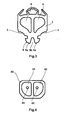
- Fig. 3 shows by way of example in cross section the male finger protection profile, wherein the Fig. 3 the finger protection profile according to Fig. 2 shows in the deformed state, when the two chambers 6 are acted upon in the profile with negative pressure, and thus contract the chambers 6. It is Immediately apparent that at negative pressure in the chambers, the wall 3 is pivoted away on both sides of the baseboard 9 of the skirting 9 and the C-shaped rail, so then when inserting the baseboard in the C-shaped rail 25, the wall 3 not the rail 25 and also not applied to the door leaf 31; or in other words, that the two Wandungsflanken are pivoted away on both sides of the baseboard of the baseboard or of the cross-sectionally C-shaped rail of the door or door portal.
- a sealing plug 40 is provided, wherein the sealing plug 40 has two of the shape of the two chambers modeled base 42 which protrude respectively when placing the sealing plug 40 in the chambers 6.
- the sealing plug 40 in each case has a valve 45 in order to connect a suction pump there.
- the profile is then inserted with the baseboard 9 in the C-shaped rail 25 of the door 30.
- a chamber 8 is provided instead of the notch, which is acted upon by negative pressure. That is, through the chamber 8 in this embodiment, the baseboard in theticianologicalnimplantation 9 a divided.
- the skirting elements 9a move toward one another in the region of the chamber 8b therebetween, that is to say in the region of the undercut 9c, 19c, so that the skirting elements no longer engage during the insertion process lie against the inside of the C-shaped rail, and thus the force during insertion is reduced accordingly.
- the female profile is formed.
Landscapes
- Engineering & Computer Science (AREA)
- Mechanical Engineering (AREA)
- Specific Sealing Or Ventilating Devices For Doors And Windows (AREA)
- Pressure Vessels And Lids Thereof (AREA)
Abstract
Description
- Die Erfindung betrifft einerseits ein aus einem Elastomer ausgebildetes Profil einer Tür oder eines Türportals eines öffentlichen Personenverkehrsmittels, z. B. einer Straßenbahn oder einer U-Bahn, wobei das Profil mindestens eine sich parallel zu Längsachse des Profils erstreckende Kammer und eine Wandung mit mindestens einer Fußleiste umfasst; andererseits betrifft die Erfindung auch ein Verfahren zur Anordnung eines Elastomerprofils an der Stirnseite einer Tür oder eines Türportals eines öffentlichen Personenverkehrsmittels, wobei das Profil mindestens eine Fußleiste zur Aufnahme durch eine Schiene der Tür oder des Türportals aufweist, und wobei das Profil sich längs des Profils erstreckend mindestens eine Kammer umfasst.
- Aus einem Elastomer ausgebildete Profile zur Anordnung an einer Tür oder einem Türportal sind aus dem Stand der Technik hinreichend bekannt. Derartige Profile dienen dazu, einen möglichen Spalt zwischen Türrahmen und Tür bzw. auch zwischen zwei aufeinander zulaufenden Türen gegen äußere Einflüsse abzudichten. Häufig sind derartige aus einem Elastomer hergestellte Profile als Fingerschutzprofile ausgebildet, wie sie beispielsweise aus der
EP 1 575 068 bekannt sind. Die Aufgabe solcher Fingerschutzprofile besteht darin, beim Schließvorgang der Tür dafür zu sorgen, dass wenn sich ein Gegenstand im Bereich des Fingerschutzprofils befindet, der Schließvorgang der Tür reversiert wird, sodass sichergestellt ist, dass weder Personen noch Gegenstände durch die Tür eingeklemmt werden. - Für die Befestigung eines solchen Elastomerprofils an einer Tür oder einem Türportal weist die Tür oder das Portal eine im Querschnitt C-förmige Schiene auf, wobei in die Schiene das Elastomerprofil mit der Fußleiste eingeschoben wird. Dieser Montagevorgang ist mit einem erheblichen Kraftaufwand verbunden. Dies gilt selbst dann, wenn das Elastomerprofil an den Stellen oder Flächen, die mit der C-förmigen Schiene unmittelbar in Berührung gelangen, mit einem Gleitmittel eingestrichen wird. Insbesondere besteht die Gefahr, dass beim Einschieben die mit der Montage beschäftigten Personen von dem Profil abrutschen, insbesondere wenn dies mit einem Gleitmittel eingestrichen ist, und sich hierbei den Unterarm an der C-förmigen Schiene aufreißen.
- Die der Erfindung zugrunde liegende Aufgabe besteht demzufolge darin, ein Profil der eingangs genannten Art derart auszubilden, dass der Montagevorgang erleichtert wird, mit dem Ziel der Verminderung von Arbeitsunfällen beim Einschieben des Elastomerprofils in die Schiene einer Tür oder eines Türportals.
- Zur Lösung der Aufgabe wird bei einem aus einem Elastomer ausgebildeten Profil der eingangs genannten Art vorgeschlagen, dass die mindestens eine Kammer des Profils derart ausgebildet ist, dass die Kammer mit Unterdruck beaufschlagbar ist. Durch die Anordnung einer mit Unterdruck beaufschlagbaren, d. h. evakuierbaren Kammer im Profil wird erreicht, dass sich die Kammer und mithin das Profil im Bereich der Kammer zusammenziehen. Durch eine geeignete Anordnung mindestens einer Kammer vorzugsweise jedoch von mehreren evakuierbaren Kammern, die sich über die Länge des Profils erstrecken, kann nun erreicht werden, dass sich an den Stellen, an denen das Profil im nicht evakuierten Zustand auf oder an der Schiene anliegt, das Profil im evakuierten Zustand von der Schiene zumindest partiell abgehoben wird und insofern die Reibung zwischen dem Profil einerseits und der Schiene andererseits vermindert oder sogar gänzlich aufgehoben wird. Das heißt, dass die Kraft, mit der das Profil auf der Schiene anliegt, wird vermindert oder sogar gänzlich aufgehoben.
- So ist nach einem Merkmal der Erfindung insbesondere vorgesehen, dass im Bereich der mindestens einen Wandung des Profils, die die Fußleiste aufnimmt, die mindestens eine Kammer angeordnet, die mit Unterdruck beaufschlagbar ist. Das heißt, die mindestens eine Kammer befindet sich innerhalb des Profils. Üblicherweise ist es bei der Montage eines solchen Elastomerprofils so, dass die Wandung des Profils, die die Fußleiste aufnimmt, unmittelbar auf der Oberseite der C-förmigen Schiene aufliegt. Hierdurch entstehen erhebliche Reibungskräfte. Dadurch nun, dass für die Montage durch die Beaufschlagung der Kammer mit Unterdruck die beiden Wandungsflanken zu beiden Seiten der Fußleiste von der die Fußleiste aufnehmenden Schiene weggeschwenkt werden, wird nun die Reibung beim Einschieben der Fußleiste in die C-förmige Schiene erheblich vermindert. Das zuvor beschriebene Abheben der Wandung zu beiden Seiten der Fußleiste wird noch dadurch begünstigt, dass die Kammer auf der Außenwandung etwa mittig eine sich längs der Kammer erstreckende Querschnittsverminderung aufweist. Insbesondere ist in diesem Zusammenhang vorgesehen, dass die Innenseite der Außenwandung eine Wandungskerbe zur Querschnittsverminderung aufweist. Diese Wandungskerbe sorgt dafür, dass an dieser Stelle die Wandung einknickt und hierdurch die Wandungsflanken der Wandung, die die Fußleiste aufnimmt, von der C-förmigen Schiene wegschwenken. Die Außenwandung ist hierbei die Wandung der Kammer, die auf die Türaußen- oder Türinnenseite zugerichtet ist.
- Nach einem weiteren Merkmal der Erfindung ist vorgesehen, dass in der Fußleiste mindestens eine Kammer angeordnet ist, die derart ausgebildet ist, dass sie mit Unterdruck beaufschlagbar ist. Zusätzlich oder alternativ zu der Kammer, durch die im evakuierten Zustand bewirkt wird, dass die Wandung von der Oberseite der C-förmigen Schiene wegverschwenkt wird, kann durch die Anordnung mindestens einer weiteren zweiten evakuierten Kammer in der Fußleiste erreicht werden, dass auch dieser Bereich Kraft vermindernd an den entsprechenden Flächen der Schiene während der Montage anliegt. Dies mit der Folge, dass die Reibung so weit vermindert wird, dass das Profil mit der Fußleiste ohne größere Kraftanstrengung in die entsprechende Schiene eingeschoben werden kann.
- Weitere vorteilhafte Merkmale und Ausgestaltung der Erfindung sind den Unteransprüchen zu entnehmen.
- So ist nach einem besonderen Merkmal der Erfindung vorgesehen, dass das Profil im Querschnitt in etwa rechteckig ausgebildet ist, wobei die von der Wandung abstehende Fußleiste auf mindestens einer Seite einen Hinterschnitt im Bereich der Wandung des Profils aufweist. Durch die zuvor beschriebene Ausbildung des Profils mit der Fußleiste wird erreicht, dass durch die C-förmige Schiene der Tür oder des Türportals das Profil mit seiner Fußleiste formschlüssig aufnehmbar ist.
- Weiterhin ist vorteilhaft die mindestens eine Kammer, die sich parallel zur Fußleiste erstreckt, verschließbar. Dies kann beispielsweise dadurch geschehen, dass ein Verschlussstopfen auf die beiden Enden des Profils aufgesetzt wird, und hierdurch die mit Unterdruck zu beaufschlagende Kammer abgesperrt ist, oder aber die Enden des Profils werden im Bereich der Kammer z. B. verklebt.
- An der mindestens einen Kammer sind vorzugsweise Mittel anbringbar, mit deren Hilfe die Kammer mit Unterdruck beaufschlagt werden kann. Dies kann beispielsweise eine entsprechende Saugeinrichtung, z. B. eine Saugpumpe, sein. Zum Anschluss ist vorteilhaft ein Ventil vorgesehen. Denkbar ist aber auch, lediglich eine Öffnung in der Kammer vorzusehen, durch die ein Schlauch geschoben wird, an dem eine Pumpe als Saugeinrichtung anbringbar ist. Zum Verschließen der Enden des Profilkörpers können Verschlussstopfen vorgesehen sein, die im Bereich der Kammern das Ventil zum Anschluss einer Saugpumpe aufweisen.
- Als vorteilhaft hat sich herausgestellt, wenn die Fußleiste zur Bildung zweier Fußleistenelemente eine längs verlaufende Kerbe aufweist, sodass die Fußleistenelemente, obwohl an der Innenseite der C-förmigen Schiene anliegend, sich dennoch von der Schiene wegbiegen können, um so das Einschieben in die Schiene zu erleichtern.
- In diesem Zusammenhang hat sich als besonders vorteilhaft herausgestellt, wenn die mindestens eine mit Unterdruck beaufschlagbare Kammer der Fußleiste dadurch gebildet wird, dass die Kerbe als geschlossener Hohlraum ausgebildet ist. Denn durch die Evakuierung der Kammer in diesem Bereich, also im Bereich der früheren Kerbe, wird erreicht, dass die Fußleistenelemente sich aufeinander zubewegen und somit nur mit geringer Kraft an den entsprechenden Innenseiten der Schenkel der C-förmigen Schiene anliegen, wenn sie überhaupt noch dort anliegen.
- Des Weiteren hat sich als vorteilhaft herausgestellt, wenn der Querschnitt der mindestens einen Kammer in dem Profil sich in Richtung auf die Fußleiste zu verjüngt. Insbesondere kann beispielsweise die Kammer im Querschnitt dreieckförmig ausgebildet sein, um das Abklappen der Wandung zu beiden Seiten der Fußleiste zu begünstigen.
- Es wurde bereits darauf hingewiesen, dass das Profil als Fingerschutzprofil ausgebildet sein kann. Zu diesem Zweck weist das Profil des Fingerschutzprofils auf der der Fußleiste gegenüberliegenden Wandung mindestens eine Kammer zur Aufnahme eines Schaltgliedes z. B. einer Schaltleiste auf.
- Sowohl ein einfaches Elastomerprofil als auch ein Elastomerprofil in Form eines Fingerschutzprofils zeigen auf der der Fußleiste gegenüberliegenden Wandung mindestens eine, vorzugsweise jedoch zwei aufeinander zugerichtete Dichtlippen, die dafür sorgen, dass Spritzwasser nicht in das Innere des Fahrzeugs gelangen kann.
- Gegenstand der Erfindung ist ebenfalls ein Verfahren zur Anordnung eines Elastomerprofils an der Stirnseite einer Tür oder eines Türportals eines öffentlichen Personenverkehrsmittels, wie es zu eingangs beschrieben worden ist. Das Montageverfahren zur Anordnung des Profils an der Stirnseite der Tür oder eines Portalrahmens zeichnet sich im Einzelnen dadurch aus, dass beim Einschieben der Fußleiste in die Schiene durch Beaufschlagung der mindestens einen Kammer mit Unterdruck die Reibung zwischen Profil und Schiene der Tür oder des Türportals, d. h. während des Einschubvorganges, vermindert ist. Betrachtet man nach einer ersten Variante den Fall, dass die mindestens eine mit Unterdruck beaufschlagbare Kammer sich innerhalb des Profils befindet, und zwar im Bereich der Wandung, die die Fußleiste aufnimmt, dann wird dann, wenn diese Kammer evakuiert ist, sich die Wandung, die die Fußleiste aufnimmt, zu beiden Seiten der Fußleiste von der Wandung der C-förmigen Schiene weg verschwenken, weil sich die Kammer unter Unterdruck zusammenzieht. Dies bewirkt eine signifikante Verminderung der Reibung zwischen Profil und Schiene.
- Zusätzlich oder alternativ kann vorgesehen sein, mindestens eine in der Fußleiste angeordnete Kammer mit Unterdruck zu beaufschlagen, um durch Zusammenziehen dieser Kammer und damit einhergehend durch eine Verminderung der Anlagekräfte zwischen Fußleiste und Schiene die Reibung zwischen Fußleiste und Schiene zu vermindern. Es wurde bereits darauf hingewiesen, dass die Fußleiste durch eine mittig verlaufende Kerbe in zwei Fußleistenelemente teilbar ist. Durch die Anordnung einer Kammer anstelle der Kerbe kann nun erreicht werden, dass die Fußleistenelemente, die an der Innenseite der C-förmigen Schiene anliegen, sich bei Unterdruck in der Kammer zusammenziehen, und so zu der weiteren Verminderung der Reibung zwischen Schiene und Profil beitragen.
- Denkbar ist aber ebenfalls, wenn in beiden Fußleistenelementen im oberen Bereich der Kerbe jeweils eine evakuierbare Kammer vorgesehen ist, wobei sich in diesem Fall dann bei Zusammenziehen der beiden Kammern durch Evakuierung die beiden Fußleistenelemente sich im Bereich der Kerbe aufeinander zubewegen werden, und mithin die Fußleistenelemente endseitig kaum oder gar keinen Kontakt mit dem entsprechenden Schenkel der Schiene, insbesondere der C-förmigen Schiene beim Einschubvorgang aufweisen.
- Anhand der Zeichnungen wird die Erfindung nachstehend beispielhaft näher erläutert.
- Fig.1
- zeigt im Schnitt ein männliches und ein weibliches Fingerschutzprofil angeordnet an einem Türportal und einer Tür oder zwischen zwei Türen;
- Fig.2
- zeigt ein männliches Fingerschutzprofil in vergrößerter Darstellung;
- Fig. 3
- zeigt eine Darstellung des männlichen Fingerschutzprofils gemäß
Fig. 2 , wobei die beiden Kammern des Fingerschutzprofils mit Unterdruck beaufschlagt sind; - Fig. 4
- zeigt den Verschlussstopfen mit dem Ventil;
- Fig. 5
- zeigt das Profil gemäß
Fig. 2 mit einer in der Fußleiste angeordneten, mit Unterdruck beaufschlagbaren Kammer; - Fig. 6
- zeigt eine Darstellung gemäß
Fig. 5 , wobei die Kammer im Bereich der Fußleiste mit Unterdruck beaufschlagt ist. - Das männliche Fingerschutzprofil 1 und das weibliche Fingerschutzprofil 10 unterscheiden sich im Wesentlichen nur dadurch, dass das männliche Fingerschutzprofil 1 im Bereich des Übergangs zum weiblichen Fingerschutzprofil 10 eine vorstehende Kammer 2 aufweist, die der Aufnahme einer Schaltleiste 4 dient. Darüber hinaus weist sowohl das männliche Fingerschutzprofil 1 als auch das weibliche Fingerschutzprofil 10 am freien Ende im Seitenbereich jeweils eine Dichtlippe 5, 15 auf, die in Richtung zum Zentrum des Fingerschutzprofils zu, abgewinkelt ist. Diese Dichtlippen 5, 15 verhindern den Eintritt von Spritzwasser in das Innere des Fahrzeugs.
- Sowohl das männliche als auch das weibliche Fingerschutzprofil besitzen im vorliegenden Fall mehrere Kammern 6, 16, die sich parallel zur Längsachse des jeweiligen Fingerschutzprofils 7, 17 als männliches oder weibliches Fingerschutzprofil erstrecken. Sowohl das männliche als auch das weibliche Fingerschutzprofil zeigen darüber hinaus jeweils eine Fußleiste 9, 19, wobei eine jede Fußleiste 9, 19 zwei parallel zueinander verlaufende Fußleistenelemente 9a, 19a aufweist, wobei die beiden parallel zueinander verlaufenden Fußleistenelemente 9a, 19a durch die mittig in der Fußleiste angeordnete Kerbe 9b, 19b gebildet werden. Die Fußleiste 9, 19 besitzt beidseitig einen Hinterschnitt 9c, 19c zur Aufnahme durch die im Querschnitt C-förmige Schiene 25 in dem Türblatt 31 der Tür 30. Die Wandung 3, 13 des jeweiligen Profils 7, 17, dass die Fußleiste 9, 19 aufnimmt, liegt sowohl an der C-förmigen Schiene 25 an, als auch an dem Türblatt 31 der Tür 30.
- Anhand der
Figuren 2 und3 sowie derFiguren 5 und 6 soll nun die Funktionsweise der Erfindung erläutert werden. -
Fig. 3 zeigt beispielhaft im Querschnitt das männliche Fingerschutzprofil, wobei dieFig. 3 das Fingerschutzprofil gemäßFig. 2 im verformten Zustand zeigt, wenn die beiden Kammern 6 in dem Profil mit Unterdruck beaufschlagt sind, und mithin sich die Kammern 6 zusammenziehen. Es ist unmittelbar erkennbar, dass bei Unterdruck in den Kammern die Wandung 3 zu beiden Seiten der Fußleiste 9 von der Fußleiste 9 bzw. der C-förmigen Schiene weggeschwenkt wird, sodass dann beim Einschieben der Fußleiste in die C-förmige Schiene 25 die Wandung 3 nicht an der Schiene 25 und auch nicht an dem Türblatt 31 anliegt; oder anders ausgedrückt, dass die beiden Wandungsflanken zu beiden Seiten der Fußleiste von der Fußleiste bzw. von der im Querschnitt C-förmigen Schiene der Tür oder des Türportals weggeschwenkt werden. Das heißt, dass die Reibung beim Einschieben des Profils in die Schiene 25 erheblich vermindert wird. Zum Verschluss der beiden Kammern 6 ist ein Verschlussstopfen 40 vorgesehen, wobei der Verschlussstopfen 40 zwei der Form der beiden Kammern nachempfundene Sockel 42 aufweist, die beim Aufsetzen des Verschlussstopfens 40 jeweils in die Kammern 6 hineinragen. Im Bereich der Kammern 6 weist der Verschlussstopfen 40 jeweils ein Ventil 45 auf, um dort eine Saugpumpe anzuschließen. Im evakuierten oder im mit Unterdruck beaufschlagten Zustand der beiden Kammern 6 wird dann das Profil mit der Fußleiste 9 in die C-förmige Schiene 25 der Tür 30 eingeschoben. - Von dem Gegenstand der Erfindung erfasst ist nicht nur eine Ausführungsform erfasst, bei der das Profil oder das Fingerschutzprofil endseitig durch einen Verschlussstopfen 40 temporär verschlossen ist, sondern auch eine Ausführungsform, bei der das Profil endseitig bereits bei der Herstellung verschlossen ist, und dem zufolge lediglich ein Ventil im Bereich der Kammern 6 angeordnet werden muss, das dem Anschluss der Saugpumpe dient.
- Bei der Darstellung gemäß
Fig. 5 die dem Profil entspricht, wie es inFig. 2 dargestellt ist, ist eine Kammer 8 anstelle der Kerbe vorgesehen, die mit Unterdruck beaufschlagbar ist. Das heißt, durch die Kammer 8 wird bei dieser Ausführungsform die Fußleiste in die Fußleistenelemente 9a unterteilt. Bei Beaufschlagung der Kammer 8 mit Unterdruck, das heißt, bei Zusammenziehen der Kammer 8 werden die Fußleistenelemente 9a sich im Bereich der dazwischen befindlichen Kammer 8b, also im Bereich des Hinterschnittes 9c, 19c, aufeinander zubewegen, sodass die Fußleistenelemente während des Einschubvorganges nicht mehr an der Innenseite der C-förmigen Schiene anliegen, und somit die Kraft beim Einschieben entsprechend vermindert ist. In gleicher Weise ist auch das weibliche Profil ausgebildet. -
- 1
- männliches Fingerschutzprofil
- 2
- vorstehende Kammer
- 3
- Wandung
- 4
- Schaltleiste
- 5
- Dichtlippe
- 6
- Kammer
- 7
- Profilkörper des männl. Fingerschutzprofils
- 8
- Kammer (anstelle der Kerbe)
- 9
- Fußleiste
- 9a
- Fußleistenelement
- 9b
- Kerbe
- 9c
- Hinterschnitt
- 10
- weibliches Fingerschutzprofil
- 13
- Wandung
- 16
- Kammer
- 17
- Profilkörper des weibl. Fingerschutzprofils
- 19
- Fußleiste
- 19a
- Fußleistenelement
- 19b
- Kerbe
- 19c
- Hinterschnitt
- 25
- C-förmige Schiene
- 30
- Tür
- 31
- Türblatt
- 40
- Verschlussstopfen
- 42
- Sockel
- 45
- Ventil
Claims (17)
- Aus einem Elastomer ausgebildetes Profil einer Tür oder eines Türportals eines öffentlichen Personenverkehrsmittels, z. B. einer Straßenbahn oder einer U-Bahn, wobei das Profil mindestens eine sich parallel zur Längsachse des Profils erstreckende Kammer (6, 16) und eine Wandung (3, 13) mit mindestens einer Fußleiste (9, 19) umfasst,
dadurch gekennzeichnet,
dass die mindestens eine Kammer (6, 8, 16) des Profils (7, 17) derart ausgebildet ist, dass die Kammer mit Unterdruck beaufschlagbar ist. - Aus einem Elastomer ausgebildetes Profil einer Tür oder eines Türportals eines öffentlichen Personenverkehrsmittels nach Anspruch 1,
dadurch gekennzeichnet,
dass im Bereich der mindestens einen Wandung (3, 13) des Profils (7, 17), die die Fußleiste (9, 19) aufnimmt, die mindestens eine Kammer (6, 16) in dem Profil angeordnet ist, die derart ausgebildet ist, dass sie mit Unterdruck beaufschlagbar ist. - Aus einem Elastomer ausgebildetes Profil einer Tür oder eines Türportals eines öffentlichen Personenverkehrsmittels nach Anspruch 1 oder 2,
dadurch gekennzeichnet,
dass in der Fußleiste (9, 19) mindestens eine Kammer (8) angeordnet ist, die derart ausgebildet ist, dass sie mit Unterdruck beaufschlagbar ist. - Aus einem Elastomer ausgebildetes Profil einer Tür oder eines Türportals eines öffentlichen Personenverkehrsmittels nach einem der voranstehenden Ansprüche,
dadurch gekennzeichnet,
dass das Profil (7, 17) im Querschnitt in etwa rechteckig ausgebildet ist, wobei die von der Wandung (3, 13) abstehende Fußleiste (9, 19) auf mindestens einer Seite einen Hinterschnitt (9c, 19c) aufweist. - Aus einem Elastomer ausgebildetes Profil einer Tür oder eines Türportals eines öffentlichen Personenverkehrsmittels nach einem der voranstehenden Ansprüche,
dadurch gekennzeichnet,
dass sich die mindestens eine Kammer (6, 8, 16) parallel zur Längsachse des Profils (7, 17) erstreckt. - Aus einem Elastomer ausgebildetes Profil einer Tür oder eines Türportals eines öffentlichen Personenverkehrsmittels nach einem der voranstehenden Ansprüche,
dadurch gekennzeichnet,
dass die mindestens eine Kammer (6, 8, 16) verschließbar ist. - Aus einem Elastomer ausgebildetes Profil einer Tür oder eines Türportals eines öffentlichen Personenverkehrsmittels nach einem der voranstehenden Ansprüche,
dadurch gekennzeichnet,
dass an der mindestens einen Kammer (6, 8, 16) Mittel zur Erzeugung eines Unterdrucks anbringbar sind. - Aus einem Elastomer ausgebildetes Profil einer Tür oder eines Türportals eines öffentlichen Personenverkehrsmittels nach Anspruch 6 oder 7,
dadurch gekennzeichnet,
dass zum Verschließen der Kammer (6, 8, 16) ein Verschlussstopfen (40) vorgesehen ist. - Aus einem Elastomer ausgebildetes Profil einer Tür oder eines Türportals eines öffentlichen Personenverkehrsmittels nach Anspruch 8,
dadurch gekennzeichnet,
dass der Verschlussstopfen (40) Mittel zum Anschluss einer Saugeinrichtung aufweist. - Aus einem Elastomer ausgebildetes Profil einer Tür oder eines Türportals eines öffentlichen Personenverkehrsmittels nach Anspruch 9,
dadurch gekennzeichnet,
dass das Mittel zum Anschluss einer Saugeinrichtung ein Ventil (45) ist. - Aus einem Elastomer ausgebildetes Profil einer Tür oder eines Türportals eines öffentlichen Personenverkehrsmittels nach einem der voranstehenden Ansprüche,
dadurch gekennzeichnet,
dass die Fußleiste (9, 19) zur Bildung zweier Fußleistenelemente (9a, 19a) eine längs verlaufende Kerbe (9b, 19b) aufweist. - Aus einem Elastomer ausgebildetes Profil einer Tür oder eines Türportals eines öffentlichen Personenverkehrsmittels nach einem der Ansprüche 3 bis 11,
dadurch gekennzeichnet,
dass die mindestens eine in der Fußleiste angeordnete mit Unterdruck beaufschlagbare Kammer (8) sich mittig in der Fußleiste befindet. - Aus einem Elastomer ausgebildetes Profil einer Tür oder eines Türportals eines öffentlichen Personenverkehrsmittels nach einem der Ansprüche 2 bis 12,
dadurch gekennzeichnet,
dass die Kammern (6, 16) in dem Profil (7, 17) in der Außenwandung eine sich längs der Außenwandung erstreckende Querschnittsverminderung aufweist. - Verfahren zur Anordnung eines Elastomerprofils an der Stirnseite einer Tür oder eines Türportals eines öffentlichen Personenverkehrsmittels, wobei das Profil mindestens eine Fußleiste (9, 19) zur Aufnahme durch eine C-förmige Schiene (25) der Tür oder des Türportals aufweist, und wobei das Profil (7, 17) sich längs des Profils erstreckend mindestens eine Kammer (6, 8, 16) umfasst,
dadurch gekennzeichnet,
dass beim Einschieben der Fußleiste (9, 19), in die Schiene, durch Beaufschlagung der mindestens einen Kammer (6, 8, 16) mit Unterdruck, die Reibung zwischen Profil und C-förmige Schiene (25) der Tür oder des Türportals während des Einschubvorganges vermindert wird. - Verfahren zur Anordnung eines Elastomerprofils an der Stirnseite einer Tür oder eines Türportals eines öffentlichen Personenverkehrsmittels nach Anspruch 14,
dadurch gekennzeichnet,
dass bei Beaufschlagung der mindestens einen Kammer (6, 16) mit Unterdruck, die sich innerhalb des Profils im Bereich der Wandung (3, 13) befindet, die die Fußleiste (9c, 19c) aufnimmt, sich die die Fußleiste aufweisende Wandung (3, 13) des Profils von der C-förmigen Schiene (25) wegverschwenkt. - Verfahren zur Anordnung eines Elastomerprofils an der Stirnseite einer Tür oder eines Türportals eines öffentlichen Personenverkehrsmittels nach Anspruch 14 oder 15,
dadurch gekennzeichnet,
dass bei Beaufschlagung der mindestens einen Kammer (8), die in der Fußleiste (9, 19) angeordnet ist, die Reibung zwischen Fußleiste und C-förmiger Schiene (25) vermindert ist. - Verfahren zur Anordnung eines Elastomerprofils an der Stirnseite einer Tür oder eines Türportals eines öffentlichen Personenverkehrsmittels nach einem der voranstehenden Ansprüche 14 bis 16,
dadurch gekennzeichnet,
dass sich die mindestens eine Kammer (6, 8, 16) unter Unterdruck zusammenzieht.
Priority Applications (3)
| Application Number | Priority Date | Filing Date | Title |
|---|---|---|---|
| EP12005433.3A EP2689949B1 (de) | 2012-07-26 | 2012-07-26 | Verfahren zur Anordnung eines Elastomerprofils an der Stirnseite einer Tür oder eines Türportals eines öffentlichen Personenverkehrsmittels |
| ES12005433.3T ES2560960T3 (es) | 2012-07-26 | 2012-07-26 | Procedimiento de disposición de un perfil de elastómero en el lado frontal de una puerta o de un portal de un medio público de transporte de personas |
| PL12005433T PL2689949T3 (pl) | 2012-07-26 | 2012-07-26 | Sposób montowania profilu z elastomeru na krawędzi czołowej skrzydła albo ościeżnicy w drzwiach w środkach komunikacji zbiorowej |
Applications Claiming Priority (1)
| Application Number | Priority Date | Filing Date | Title |
|---|---|---|---|
| EP12005433.3A EP2689949B1 (de) | 2012-07-26 | 2012-07-26 | Verfahren zur Anordnung eines Elastomerprofils an der Stirnseite einer Tür oder eines Türportals eines öffentlichen Personenverkehrsmittels |
Publications (2)
| Publication Number | Publication Date |
|---|---|
| EP2689949A1 true EP2689949A1 (de) | 2014-01-29 |
| EP2689949B1 EP2689949B1 (de) | 2016-01-13 |
Family
ID=46639943
Family Applications (1)
| Application Number | Title | Priority Date | Filing Date |
|---|---|---|---|
| EP12005433.3A Active EP2689949B1 (de) | 2012-07-26 | 2012-07-26 | Verfahren zur Anordnung eines Elastomerprofils an der Stirnseite einer Tür oder eines Türportals eines öffentlichen Personenverkehrsmittels |
Country Status (3)
| Country | Link |
|---|---|
| EP (1) | EP2689949B1 (de) |
| ES (1) | ES2560960T3 (de) |
| PL (1) | PL2689949T3 (de) |
Cited By (2)
| Publication number | Priority date | Publication date | Assignee | Title |
|---|---|---|---|---|
| WO2016030611A1 (fr) | 2014-08-28 | 2016-03-03 | Faiveley Transport Tours | Système d'étanchéité pour un ouvrant comportant un profile recevant un joint d'étanchéité verrouille par une clé coulissante |
| US11383739B2 (en) | 2018-12-27 | 2022-07-12 | Westinghouse Air Brake Technologies Corporation | Seal retention device |
Citations (3)
| Publication number | Priority date | Publication date | Assignee | Title |
|---|---|---|---|---|
| DE10044071A1 (de) * | 2000-09-07 | 2002-04-04 | Daimler Chrysler Ag | Dichtungssystem für eine Tür, insbesondere an einem Fahrzeug |
| DE20311653U1 (de) * | 2003-07-29 | 2003-10-02 | Gebr. Bode GmbH & Co. KG, 34123 Kassel | Dichtungseinrichtung an einer Schwenkschiebetür für Fahrzeuge zur Personenbeförderung, insbesondere Schienenfahrzeuge |
| EP1575068A2 (de) | 2004-02-25 | 2005-09-14 | HÜBNER GmbH | Fingerschutzprofil |
-
2012
- 2012-07-26 EP EP12005433.3A patent/EP2689949B1/de active Active
- 2012-07-26 ES ES12005433.3T patent/ES2560960T3/es active Active
- 2012-07-26 PL PL12005433T patent/PL2689949T3/pl unknown
Patent Citations (3)
| Publication number | Priority date | Publication date | Assignee | Title |
|---|---|---|---|---|
| DE10044071A1 (de) * | 2000-09-07 | 2002-04-04 | Daimler Chrysler Ag | Dichtungssystem für eine Tür, insbesondere an einem Fahrzeug |
| DE20311653U1 (de) * | 2003-07-29 | 2003-10-02 | Gebr. Bode GmbH & Co. KG, 34123 Kassel | Dichtungseinrichtung an einer Schwenkschiebetür für Fahrzeuge zur Personenbeförderung, insbesondere Schienenfahrzeuge |
| EP1575068A2 (de) | 2004-02-25 | 2005-09-14 | HÜBNER GmbH | Fingerschutzprofil |
Cited By (3)
| Publication number | Priority date | Publication date | Assignee | Title |
|---|---|---|---|---|
| WO2016030611A1 (fr) | 2014-08-28 | 2016-03-03 | Faiveley Transport Tours | Système d'étanchéité pour un ouvrant comportant un profile recevant un joint d'étanchéité verrouille par une clé coulissante |
| CN106715227A (zh) * | 2014-08-28 | 2017-05-24 | 法维莱运输图尔公司 | 包括接纳由滑动键锁定的密封件的型材构件的可打开面板的密封系统 |
| US11383739B2 (en) | 2018-12-27 | 2022-07-12 | Westinghouse Air Brake Technologies Corporation | Seal retention device |
Also Published As
| Publication number | Publication date |
|---|---|
| ES2560960T3 (es) | 2016-02-23 |
| EP2689949B1 (de) | 2016-01-13 |
| PL2689949T3 (pl) | 2016-05-31 |
Similar Documents
| Publication | Publication Date | Title |
|---|---|---|
| DE69201864T2 (de) | Methode zum verbinden von bauteilen, profil und baueinheit mit einer vielzahl von profilen. | |
| CH676376A5 (en) | Strip-type door-leaf seal | |
| EP2689949B1 (de) | Verfahren zur Anordnung eines Elastomerprofils an der Stirnseite einer Tür oder eines Türportals eines öffentlichen Personenverkehrsmittels | |
| EP0101810A2 (de) | Elastomeres Profilband für Dehnungsfugen | |
| DE102017002243A1 (de) | Fahrzeugtür | |
| EP2810804A1 (de) | Dichtungsprofil einer Türspaltabdichtung eines Fahrzeuges | |
| EP0085355B1 (de) | Vorrichtung zur Verbindung von Luftkanalelementen, die an ihren Stossrändern mit Aufnahmen für Eckwinkel bildenden Flanschprofilen versehen sind | |
| EP3112577A1 (de) | Absenkdichtung | |
| DE102004055800A1 (de) | Flügel für ein Fenster oder eine Tür | |
| DE102004014598B4 (de) | Stoßverbinder zur Verbindung von Profilen | |
| DE19736467C2 (de) | Statische Dichtung | |
| EP3188919B2 (de) | Türdichtungsvorrichtung, türdichtungssystem und türflügel für ein schienenfahrzeug | |
| DE9207608U1 (de) | Elastische Strangdichtung für Fenster, Türen o.dgl. | |
| EP3712444B1 (de) | Profilverbund | |
| DE29808406U1 (de) | Dichtung, insbesondere für Fenster, Türen o.dgl. sowie entsprechendes Dichtungsprofil | |
| DE3243692A1 (de) | Abstandhalterrahmen fuer randverklebte isolierglasscheiben | |
| EP3825506A1 (de) | Rollladenkasten mit einer stirnhaube | |
| DE202021101970U1 (de) | Profilverbund | |
| DE102012100153A1 (de) | Seitenführung für Rollläden und Jalousien | |
| EP3530861A1 (de) | Horizontalrahmenteil für einen schiebetür-und/oder schiebefensterrahmen, schiebetür- und/oder schiebefensterrahmen sowie schiebetür- und/oder schiebefenstersystem | |
| EP3783180B1 (de) | Verstärkungsprofilfixierung | |
| DE10310821B4 (de) | Vorrichtung zur Verbindung zweier Hohlprofile eines Rahmens zur Aufnahme von Lichtkuppelelementen | |
| DE102009001703A1 (de) | Strangförmiges Dichtungsprofil | |
| EP3292012B1 (de) | Vorrichtung zur befestigung einer plane, insbesondere auf einem lkw-aufbau | |
| DE10150833B4 (de) | Gummielastische Dichtung, insbesondere für Außenschwingtüren bei Fahrzeugen |
Legal Events
| Date | Code | Title | Description |
|---|---|---|---|
| PUAI | Public reference made under article 153(3) epc to a published international application that has entered the european phase |
Free format text: ORIGINAL CODE: 0009012 |
|
| 17P | Request for examination filed |
Effective date: 20130305 |
|
| AK | Designated contracting states |
Kind code of ref document: A1 Designated state(s): AL AT BE BG CH CY CZ DE DK EE ES FI FR GB GR HR HU IE IS IT LI LT LU LV MC MK MT NL NO PL PT RO RS SE SI SK SM TR |
|
| AX | Request for extension of the european patent |
Extension state: BA ME |
|
| GRAP | Despatch of communication of intention to grant a patent |
Free format text: ORIGINAL CODE: EPIDOSNIGR1 |
|
| RIC1 | Information provided on ipc code assigned before grant |
Ipc: B60J 10/00 20060101AFI20150206BHEP |
|
| INTG | Intention to grant announced |
Effective date: 20150304 |
|
| RAP1 | Party data changed (applicant data changed or rights of an application transferred) |
Owner name: HUEBNER GMBH & CO. KG |
|
| RIN1 | Information on inventor provided before grant (corrected) |
Inventor name: DER ANDERE ERFINDER HAT AUF SEINE NENNUNG VERZICHT Inventor name: AREND, ULRICH |
|
| GRAS | Grant fee paid |
Free format text: ORIGINAL CODE: EPIDOSNIGR3 |
|
| GRAP | Despatch of communication of intention to grant a patent |
Free format text: ORIGINAL CODE: EPIDOSNIGR1 |
|
| RAP1 | Party data changed (applicant data changed or rights of an application transferred) |
Owner name: GEBR. BODE GMBH & CO. KG |
|
| INTG | Intention to grant announced |
Effective date: 20150930 |
|
| RAP1 | Party data changed (applicant data changed or rights of an application transferred) |
Owner name: GEBR. BODE GMBH & CO. KG Owner name: HUEBNER GMBH & CO. KG |
|
| GRAA | (expected) grant |
Free format text: ORIGINAL CODE: 0009210 |
|
| RIN1 | Information on inventor provided before grant (corrected) |
Inventor name: DER ANDERE ERFINDER HAT AUF SEINE NENNUNG VERZICHT Inventor name: AREND, ULRICH |
|
| AK | Designated contracting states |
Kind code of ref document: B1 Designated state(s): AL AT BE BG CH CY CZ DE DK EE ES FI FR GB GR HR HU IE IS IT LI LT LU LV MC MK MT NL NO PL PT RO RS SE SI SK SM TR |
|
| REG | Reference to a national code |
Ref country code: GB Ref legal event code: FG4D Free format text: NOT ENGLISH |
|
| REG | Reference to a national code |
Ref country code: CH Ref legal event code: EP |
|
| REG | Reference to a national code |
Ref country code: IE Ref legal event code: FG4D Free format text: LANGUAGE OF EP DOCUMENT: GERMAN |
|
| REG | Reference to a national code |
Ref country code: AT Ref legal event code: REF Ref document number: 770261 Country of ref document: AT Kind code of ref document: T Effective date: 20160215 |
|
| REG | Reference to a national code |
Ref country code: ES Ref legal event code: FG2A Ref document number: 2560960 Country of ref document: ES Kind code of ref document: T3 Effective date: 20160223 |
|
| REG | Reference to a national code |
Ref country code: DE Ref legal event code: R096 Ref document number: 502012005692 Country of ref document: DE |
|
| REG | Reference to a national code |
Ref country code: NL Ref legal event code: FP |
|
| REG | Reference to a national code |
Ref country code: LT Ref legal event code: MG4D |
|
| REG | Reference to a national code |
Ref country code: FR Ref legal event code: PLFP Year of fee payment: 5 |
|
| PG25 | Lapsed in a contracting state [announced via postgrant information from national office to epo] |
Ref country code: FI Free format text: LAPSE BECAUSE OF FAILURE TO SUBMIT A TRANSLATION OF THE DESCRIPTION OR TO PAY THE FEE WITHIN THE PRESCRIBED TIME-LIMIT Effective date: 20160113 Ref country code: HR Free format text: LAPSE BECAUSE OF FAILURE TO SUBMIT A TRANSLATION OF THE DESCRIPTION OR TO PAY THE FEE WITHIN THE PRESCRIBED TIME-LIMIT Effective date: 20160113 Ref country code: NO Free format text: LAPSE BECAUSE OF FAILURE TO SUBMIT A TRANSLATION OF THE DESCRIPTION OR TO PAY THE FEE WITHIN THE PRESCRIBED TIME-LIMIT Effective date: 20160413 |
|
| PG25 | Lapsed in a contracting state [announced via postgrant information from national office to epo] |
Ref country code: LT Free format text: LAPSE BECAUSE OF FAILURE TO SUBMIT A TRANSLATION OF THE DESCRIPTION OR TO PAY THE FEE WITHIN THE PRESCRIBED TIME-LIMIT Effective date: 20160113 Ref country code: SE Free format text: LAPSE BECAUSE OF FAILURE TO SUBMIT A TRANSLATION OF THE DESCRIPTION OR TO PAY THE FEE WITHIN THE PRESCRIBED TIME-LIMIT Effective date: 20160113 Ref country code: PT Free format text: LAPSE BECAUSE OF FAILURE TO SUBMIT A TRANSLATION OF THE DESCRIPTION OR TO PAY THE FEE WITHIN THE PRESCRIBED TIME-LIMIT Effective date: 20160513 Ref country code: IS Free format text: LAPSE BECAUSE OF FAILURE TO SUBMIT A TRANSLATION OF THE DESCRIPTION OR TO PAY THE FEE WITHIN THE PRESCRIBED TIME-LIMIT Effective date: 20160513 Ref country code: RS Free format text: LAPSE BECAUSE OF FAILURE TO SUBMIT A TRANSLATION OF THE DESCRIPTION OR TO PAY THE FEE WITHIN THE PRESCRIBED TIME-LIMIT Effective date: 20160113 Ref country code: LV Free format text: LAPSE BECAUSE OF FAILURE TO SUBMIT A TRANSLATION OF THE DESCRIPTION OR TO PAY THE FEE WITHIN THE PRESCRIBED TIME-LIMIT Effective date: 20160113 |
|
| REG | Reference to a national code |
Ref country code: DE Ref legal event code: R097 Ref document number: 502012005692 Country of ref document: DE |
|
| PG25 | Lapsed in a contracting state [announced via postgrant information from national office to epo] |
Ref country code: EE Free format text: LAPSE BECAUSE OF FAILURE TO SUBMIT A TRANSLATION OF THE DESCRIPTION OR TO PAY THE FEE WITHIN THE PRESCRIBED TIME-LIMIT Effective date: 20160113 Ref country code: DK Free format text: LAPSE BECAUSE OF FAILURE TO SUBMIT A TRANSLATION OF THE DESCRIPTION OR TO PAY THE FEE WITHIN THE PRESCRIBED TIME-LIMIT Effective date: 20160113 |
|
| PLBE | No opposition filed within time limit |
Free format text: ORIGINAL CODE: 0009261 |
|
| STAA | Information on the status of an ep patent application or granted ep patent |
Free format text: STATUS: NO OPPOSITION FILED WITHIN TIME LIMIT |
|
| PG25 | Lapsed in a contracting state [announced via postgrant information from national office to epo] |
Ref country code: RO Free format text: LAPSE BECAUSE OF FAILURE TO SUBMIT A TRANSLATION OF THE DESCRIPTION OR TO PAY THE FEE WITHIN THE PRESCRIBED TIME-LIMIT Effective date: 20160113 Ref country code: SK Free format text: LAPSE BECAUSE OF FAILURE TO SUBMIT A TRANSLATION OF THE DESCRIPTION OR TO PAY THE FEE WITHIN THE PRESCRIBED TIME-LIMIT Effective date: 20160113 Ref country code: SM Free format text: LAPSE BECAUSE OF FAILURE TO SUBMIT A TRANSLATION OF THE DESCRIPTION OR TO PAY THE FEE WITHIN THE PRESCRIBED TIME-LIMIT Effective date: 20160113 |
|
| 26N | No opposition filed |
Effective date: 20161014 |
|
| PG25 | Lapsed in a contracting state [announced via postgrant information from national office to epo] |
Ref country code: BE Free format text: LAPSE BECAUSE OF NON-PAYMENT OF DUE FEES Effective date: 20160731 |
|
| PG25 | Lapsed in a contracting state [announced via postgrant information from national office to epo] |
Ref country code: BG Free format text: LAPSE BECAUSE OF FAILURE TO SUBMIT A TRANSLATION OF THE DESCRIPTION OR TO PAY THE FEE WITHIN THE PRESCRIBED TIME-LIMIT Effective date: 20160413 Ref country code: SI Free format text: LAPSE BECAUSE OF FAILURE TO SUBMIT A TRANSLATION OF THE DESCRIPTION OR TO PAY THE FEE WITHIN THE PRESCRIBED TIME-LIMIT Effective date: 20160113 |
|
| PG25 | Lapsed in a contracting state [announced via postgrant information from national office to epo] |
Ref country code: MC Free format text: LAPSE BECAUSE OF FAILURE TO SUBMIT A TRANSLATION OF THE DESCRIPTION OR TO PAY THE FEE WITHIN THE PRESCRIBED TIME-LIMIT Effective date: 20160113 |
|
| REG | Reference to a national code |
Ref country code: IE Ref legal event code: MM4A |
|
| REG | Reference to a national code |
Ref country code: FR Ref legal event code: PLFP Year of fee payment: 6 |
|
| PG25 | Lapsed in a contracting state [announced via postgrant information from national office to epo] |
Ref country code: IE Free format text: LAPSE BECAUSE OF NON-PAYMENT OF DUE FEES Effective date: 20160726 |
|
| PG25 | Lapsed in a contracting state [announced via postgrant information from national office to epo] |
Ref country code: LU Free format text: LAPSE BECAUSE OF NON-PAYMENT OF DUE FEES Effective date: 20160726 |
|
| PG25 | Lapsed in a contracting state [announced via postgrant information from national office to epo] |
Ref country code: CY Free format text: LAPSE BECAUSE OF FAILURE TO SUBMIT A TRANSLATION OF THE DESCRIPTION OR TO PAY THE FEE WITHIN THE PRESCRIBED TIME-LIMIT Effective date: 20160113 Ref country code: HU Free format text: LAPSE BECAUSE OF FAILURE TO SUBMIT A TRANSLATION OF THE DESCRIPTION OR TO PAY THE FEE WITHIN THE PRESCRIBED TIME-LIMIT; INVALID AB INITIO Effective date: 20120726 |
|
| PG25 | Lapsed in a contracting state [announced via postgrant information from national office to epo] |
Ref country code: MT Free format text: LAPSE BECAUSE OF FAILURE TO SUBMIT A TRANSLATION OF THE DESCRIPTION OR TO PAY THE FEE WITHIN THE PRESCRIBED TIME-LIMIT Effective date: 20160113 Ref country code: MK Free format text: LAPSE BECAUSE OF FAILURE TO SUBMIT A TRANSLATION OF THE DESCRIPTION OR TO PAY THE FEE WITHIN THE PRESCRIBED TIME-LIMIT Effective date: 20160113 Ref country code: GR Free format text: LAPSE BECAUSE OF FAILURE TO SUBMIT A TRANSLATION OF THE DESCRIPTION OR TO PAY THE FEE WITHIN THE PRESCRIBED TIME-LIMIT Effective date: 20160113 |
|
| REG | Reference to a national code |
Ref country code: FR Ref legal event code: PLFP Year of fee payment: 7 |
|
| PG25 | Lapsed in a contracting state [announced via postgrant information from national office to epo] |
Ref country code: AL Free format text: LAPSE BECAUSE OF FAILURE TO SUBMIT A TRANSLATION OF THE DESCRIPTION OR TO PAY THE FEE WITHIN THE PRESCRIBED TIME-LIMIT Effective date: 20160113 |
|
| PGFP | Annual fee paid to national office [announced via postgrant information from national office to epo] |
Ref country code: NL Payment date: 20210721 Year of fee payment: 10 |
|
| PGFP | Annual fee paid to national office [announced via postgrant information from national office to epo] |
Ref country code: AT Payment date: 20210722 Year of fee payment: 10 Ref country code: IT Payment date: 20210727 Year of fee payment: 10 Ref country code: FR Payment date: 20210729 Year of fee payment: 10 |
|
| PGFP | Annual fee paid to national office [announced via postgrant information from national office to epo] |
Ref country code: ES Payment date: 20210927 Year of fee payment: 10 Ref country code: GB Payment date: 20210722 Year of fee payment: 10 Ref country code: CH Payment date: 20210721 Year of fee payment: 10 |
|
| PGFP | Annual fee paid to national office [announced via postgrant information from national office to epo] |
Ref country code: PL Payment date: 20220622 Year of fee payment: 11 |
|
| PGFP | Annual fee paid to national office [announced via postgrant information from national office to epo] |
Ref country code: TR Payment date: 20220722 Year of fee payment: 11 Ref country code: DE Payment date: 20220627 Year of fee payment: 11 Ref country code: CZ Payment date: 20220722 Year of fee payment: 11 |
|
| REG | Reference to a national code |
Ref country code: CH Ref legal event code: PL |
|
| REG | Reference to a national code |
Ref country code: NL Ref legal event code: MM Effective date: 20220801 |
|
| REG | Reference to a national code |
Ref country code: AT Ref legal event code: MM01 Ref document number: 770261 Country of ref document: AT Kind code of ref document: T Effective date: 20220726 |
|
| GBPC | Gb: european patent ceased through non-payment of renewal fee |
Effective date: 20220726 |
|
| PG25 | Lapsed in a contracting state [announced via postgrant information from national office to epo] |
Ref country code: LI Free format text: LAPSE BECAUSE OF NON-PAYMENT OF DUE FEES Effective date: 20220731 Ref country code: FR Free format text: LAPSE BECAUSE OF NON-PAYMENT OF DUE FEES Effective date: 20220731 Ref country code: CH Free format text: LAPSE BECAUSE OF NON-PAYMENT OF DUE FEES Effective date: 20220731 Ref country code: AT Free format text: LAPSE BECAUSE OF NON-PAYMENT OF DUE FEES Effective date: 20220726 |
|
| PG25 | Lapsed in a contracting state [announced via postgrant information from national office to epo] |
Ref country code: GB Free format text: LAPSE BECAUSE OF NON-PAYMENT OF DUE FEES Effective date: 20220726 |
|
| PG25 | Lapsed in a contracting state [announced via postgrant information from national office to epo] |
Ref country code: NL Free format text: LAPSE BECAUSE OF NON-PAYMENT OF DUE FEES Effective date: 20220801 |
|
| PG25 | Lapsed in a contracting state [announced via postgrant information from national office to epo] |
Ref country code: IT Free format text: LAPSE BECAUSE OF NON-PAYMENT OF DUE FEES Effective date: 20220726 |
|
| REG | Reference to a national code |
Ref country code: ES Ref legal event code: FD2A Effective date: 20230926 |
|
| PG25 | Lapsed in a contracting state [announced via postgrant information from national office to epo] |
Ref country code: ES Free format text: LAPSE BECAUSE OF NON-PAYMENT OF DUE FEES Effective date: 20220727 |
|
| REG | Reference to a national code |
Ref country code: DE Ref legal event code: R119 Ref document number: 502012005692 Country of ref document: DE |
|
| PG25 | Lapsed in a contracting state [announced via postgrant information from national office to epo] |
Ref country code: DE Free format text: LAPSE BECAUSE OF NON-PAYMENT OF DUE FEES Effective date: 20240201 Ref country code: CZ Free format text: LAPSE BECAUSE OF NON-PAYMENT OF DUE FEES Effective date: 20230726 |