EP2689917B1 - Method for producing a pressure hose, and pressure hose so produced - Google Patents
Method for producing a pressure hose, and pressure hose so produced Download PDFInfo
- Publication number
- EP2689917B1 EP2689917B1 EP12005407.7A EP12005407A EP2689917B1 EP 2689917 B1 EP2689917 B1 EP 2689917B1 EP 12005407 A EP12005407 A EP 12005407A EP 2689917 B1 EP2689917 B1 EP 2689917B1
- Authority
- EP
- European Patent Office
- Prior art keywords
- hose
- tube
- fabric
- hose element
- injection moulding
- Prior art date
- Legal status (The legal status is an assumption and is not a legal conclusion. Google has not performed a legal analysis and makes no representation as to the accuracy of the status listed.)
- Not-in-force
Links
Images


Classifications
-
- F—MECHANICAL ENGINEERING; LIGHTING; HEATING; WEAPONS; BLASTING
- F02—COMBUSTION ENGINES; HOT-GAS OR COMBUSTION-PRODUCT ENGINE PLANTS
- F02M—SUPPLYING COMBUSTION ENGINES IN GENERAL WITH COMBUSTIBLE MIXTURES OR CONSTITUENTS THEREOF
- F02M35/00—Combustion-air cleaners, air intakes, intake silencers, or induction systems specially adapted for, or arranged on, internal-combustion engines
- F02M35/10—Air intakes; Induction systems
- F02M35/1034—Manufacturing and assembling intake systems
- F02M35/10347—Moulding, casting or the like
-
- B—PERFORMING OPERATIONS; TRANSPORTING
- B29—WORKING OF PLASTICS; WORKING OF SUBSTANCES IN A PLASTIC STATE IN GENERAL
- B29C—SHAPING OR JOINING OF PLASTICS; SHAPING OF MATERIAL IN A PLASTIC STATE, NOT OTHERWISE PROVIDED FOR; AFTER-TREATMENT OF THE SHAPED PRODUCTS, e.g. REPAIRING
- B29C45/00—Injection moulding, i.e. forcing the required volume of moulding material through a nozzle into a closed mould; Apparatus therefor
- B29C45/16—Making multilayered or multicoloured articles
- B29C45/1671—Making multilayered or multicoloured articles with an insert
-
- B—PERFORMING OPERATIONS; TRANSPORTING
- B29—WORKING OF PLASTICS; WORKING OF SUBSTANCES IN A PLASTIC STATE IN GENERAL
- B29C—SHAPING OR JOINING OF PLASTICS; SHAPING OF MATERIAL IN A PLASTIC STATE, NOT OTHERWISE PROVIDED FOR; AFTER-TREATMENT OF THE SHAPED PRODUCTS, e.g. REPAIRING
- B29C45/00—Injection moulding, i.e. forcing the required volume of moulding material through a nozzle into a closed mould; Apparatus therefor
- B29C45/16—Making multilayered or multicoloured articles
- B29C45/1676—Making multilayered or multicoloured articles using a soft material and a rigid material, e.g. making articles with a sealing part
-
- F—MECHANICAL ENGINEERING; LIGHTING; HEATING; WEAPONS; BLASTING
- F16—ENGINEERING ELEMENTS AND UNITS; GENERAL MEASURES FOR PRODUCING AND MAINTAINING EFFECTIVE FUNCTIONING OF MACHINES OR INSTALLATIONS; THERMAL INSULATION IN GENERAL
- F16L—PIPES; JOINTS OR FITTINGS FOR PIPES; SUPPORTS FOR PIPES, CABLES OR PROTECTIVE TUBING; MEANS FOR THERMAL INSULATION IN GENERAL
- F16L11/00—Hoses, i.e. flexible pipes
- F16L11/04—Hoses, i.e. flexible pipes made of rubber or flexible plastics
- F16L11/08—Hoses, i.e. flexible pipes made of rubber or flexible plastics with reinforcements embedded in the wall
- F16L11/085—Hoses, i.e. flexible pipes made of rubber or flexible plastics with reinforcements embedded in the wall comprising one or more braided layers
-
- B—PERFORMING OPERATIONS; TRANSPORTING
- B29—WORKING OF PLASTICS; WORKING OF SUBSTANCES IN A PLASTIC STATE IN GENERAL
- B29C—SHAPING OR JOINING OF PLASTICS; SHAPING OF MATERIAL IN A PLASTIC STATE, NOT OTHERWISE PROVIDED FOR; AFTER-TREATMENT OF THE SHAPED PRODUCTS, e.g. REPAIRING
- B29C45/00—Injection moulding, i.e. forcing the required volume of moulding material through a nozzle into a closed mould; Apparatus therefor
- B29C45/16—Making multilayered or multicoloured articles
- B29C45/1671—Making multilayered or multicoloured articles with an insert
- B29C2045/1673—Making multilayered or multicoloured articles with an insert injecting the first layer, then feeding the insert, then injecting the second layer
-
- B—PERFORMING OPERATIONS; TRANSPORTING
- B29—WORKING OF PLASTICS; WORKING OF SUBSTANCES IN A PLASTIC STATE IN GENERAL
- B29C—SHAPING OR JOINING OF PLASTICS; SHAPING OF MATERIAL IN A PLASTIC STATE, NOT OTHERWISE PROVIDED FOR; AFTER-TREATMENT OF THE SHAPED PRODUCTS, e.g. REPAIRING
- B29C61/00—Shaping by liberation of internal stresses; Making preforms having internal stresses; Apparatus therefor
- B29C61/02—Thermal shrinking
-
- B—PERFORMING OPERATIONS; TRANSPORTING
- B29—WORKING OF PLASTICS; WORKING OF SUBSTANCES IN A PLASTIC STATE IN GENERAL
- B29D—PRODUCING PARTICULAR ARTICLES FROM PLASTICS OR FROM SUBSTANCES IN A PLASTIC STATE
- B29D23/00—Producing tubular articles
- B29D23/001—Pipes; Pipe joints
Definitions
- the invention relates to a method for producing a pressure hose.
- Pressure hoses are used in particular in the field of motor vehicles, for example on turbochargers. But especially in the field of household and commercial cleaning machines, such as dishwashers and washing machines, pressure hoses are used.
- the production of such pressure hoses is relatively expensive.
- an inner layer or an inner tube is first extruded, which is subsequently wrapped with a fabric strip.
- an outer layer is extruded onto the inner tube wound in this way. Thereafter, the extruded tube is cut into pieces which are pulled individually onto a core. On the core of each tube section is annealed and thus receives its final shape.
- a method of manufacturing a pressure hose comprising the steps of injection molding a tubular first hose member, applying a fabric hose externally to the first hose member, and injection molding a tubular second one Hose element comprises around the first hose element and the fabric hose pulled over it.
- the invention has for its object to provide a method for producing a pressure hose, which in comparison to the previous procedure is even more cost-effective and leads to a higher quality pressure hose.
- a method for producing a pressure hose is provided with the following steps: injection molding of a tubular first hose element, drawing a fabric hose on the outside of the first hose element, injection molding of a tubular second hose element around the first hose element and the fabric hose drawn above, in which for the injection molding of the first Hose element is selected a plastic having a hardness which is greater than the hardness of the plastic chosen for the injection molding of the second tubular element.
- the first tube member is at least slightly stiffer than the second tube member.
- it is easier to injection mold the second hose member because the first hose member provides a more stable and stiffer basic structure for the subsequent second injection molding.
- the pressure hose thus produced can have a high degree of flexibility, which is advantageous in terms of the assembly of such a pressure hose and its behavior during shock, vibration and vibration during operation.
- a plastic i. an organic polymer selected from the group of thermoplastics, thermosets and elastomers, selected from the group of elastomers or thermoplastics having a Shore A hardness which is at least more than 5, preferably more than 10 greater than the Shore A hardness of the the injection molding of the second tube element selected plastic.
- the following elastomers are preferably selected: CM, AEM, HT-AEM, FPM and ACM with a filler content (in particular aramid fiber) of up to 20%.
- the Shore hardness of the selected plastic of the first tubular element is preferably 50 Shore A to 90 Shore A.
- the plastic is preferably chosen so that it can withstand a temperature load of -40 ° C to + 230 ° C.
- the second tube element is preferably made of CM, AEM, HT-AEM, FPM or ACM with a filler content of up to 5%.
- the Shore hardness of the plastic of the second tubular element is preferably between 40 Shore A and 80 Shore A. Preference is given to using very easily flowing types of plastic. These plastics also preferably withstand temperatures between -40 ° C and + 230 ° C.
- first tubular element During injection molding of the first tubular element, it is preferably made longer at at least one of its ends than subsequently the second tubular element, so that the injection molding of the second tubular element produces a subsequently projecting tube section of the first tubular element.
- the fabric hose can be guided over the first hose element and then shrunk. Furthermore, the first tube element and / or the tissue tube arranged above it can be held on the protruding tube section during the injection molding of the second tube element.
- the protruding tube section of the first tubular element is held stationary.
- the projecting hose section of the first hose element is particularly preferably clamped.
- the fabric hose When the fabric hose is pulled on, the fabric hose is advantageously positioned in such a way that it also extends at least partially over the protruding hose section of the first hose element.
- the projecting hose section of the first hose element is preferably removed before using the pressure hose.
- the protruding tube section can be cut off or punched down from the pressure hose.
- the method according to the invention preferably further comprises the step of shrinking the fabric hose onto the first hose element, in particular after the fabric hose has been pulled on the outside of the first hose element.
- the associated warp threads and weft threads are preferably designed with different material compositions.
- the heat-shrinkable tube particularly preferably has different shrinkage behavior in its longitudinal and circumferential direction.
- the warp threads are preferably more shrinkable than the weft threads.
- the warp threads are at least 25% shrinkable and / or of pure thermoplastic, in particular polyester.
- the weft threads are preferably at most 15% shrinkable and / or have a shrinkable and a non-shrinkable component.
- the weft threads are particularly preferably designed from polyphenylene sulfide fibers and meta-amide, these materials preferably being twisted together.
- the weft threads are preferably designed as a cross thread.
- the shrinkable component is advantageously formed by straight filaments.
- a method 10 for producing a pressure hose 12 which comprises as a first essential step 14 an injection molding of a tubular first hose element 16 on an insert core 18.
- the insert core 18 is in this case in a first injection mold 24 formed from two halves 20 and 22, into which a first plastic 26 having a Shore hardness of 70 Shore A, in this case ACM with 15% aramid fiber, is injected under high pressure and high temperature.
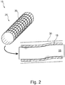
- the first tube member 16 is removed from the first injection mold 24 and wound in a step 28 designed as a shrink tube fabric tube 30 outside of the first tube member 16.
- the fabric tube 30 is sized so large in diameter that it can be slid over the entire length of the first tube member 16 away on this loosely. This is in Fig. 2 illustrated with a distance between the outside of the first tube member 16 and the fabric tube 30.
- the associated warp threads and weft threads are designed with different material compositions.
- the warp threads are 40% shrinkable and made of pure thermoplastic, in this case polyester, formed by straight filaments.
- the weft threads are only 10% shrinkable and have a shrinkable and a non-shrinkable component. They are designed with polyphenylene sulfide fibers and meta-amide, these materials being twisted together.
- the weft threads are designed as cross-thread.
- the warp threads are therefore more shrinkable than the weft threads.
- the fabric tube 30 designed as a shrink tube has a low shrinkage behavior in its longitudinal direction and a strong shrinkage behavior in its circumferential direction.
- a subsequent step 32 of shrink-fitting the fabric tube 30 onto the outer surface of the first tubular member 16 is illustrated.
- hot air 34 is blown by means of a blowing device 36 on the outer surface of the first tube member 16 and the tissue tube 30 located above it.
- the shrinkable threads of the fabric tube 30 shorten and this is applied to the outer surface of the first tube member 16 completely.
- the fabric tube 30 is dimensioned so long that it extends over the entire longitudinal extent of the first tubular element 16, in particular substantially also over the left and right, outer end region or tube section 38.
- the first tube member 16 is located during the coating and shrinking of the fabric tube 30 continues on the insert core 18, which has been previously removed only from the first injection mold.
- the fabric tube 30 is trimmed before or after shrinking at its two ends so that it does not or only slightly protrudes beyond the associated ends of the first tubular member 16.
- a tubular second tube member 42 is injection molded around the first tube member 16 and the overstretched and shrunken tissue tube 30.
- the insert core 18 is for this purpose together with the first tube member 16 and the shrunk-on fabric tube 30 in a second injection mold 48, which again consists of two halves 44 and 46.
- the two halves 44 and 46 of the second injection mold 48 clamp the two above-mentioned, outer tube portions 38 of the first tube member 16 and shrunk in these tube sections 38 fabric tube 30. In this way, the first tube member 16 and the fabric tube 30 in the second Injection mold 48 with high dimensional accuracy held at its tube sections 38 in position.
- the second plastic used is 50 ACM with a filler content of 3%.
- the Shore hardness of this plastic is about 50 Shore A.
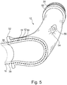
- the second plastic 50 is injected into the second injection mold 48, wherein in this second injection molding at the pressure hose 12 at the same time two End flanges 52 are formed as connecting elements.
- a cable clip 54 is formed as a connecting element in the middle of the wall of the pressure hose 12 with a metallic insert 56 arranged therein.
- one or more bellows can be formed in an embodiment of a pressure hose 12, not shown.
- different wall thicknesses can be realized in sections of different proportions of material, in particular to optimize the mobility of the pressure hose with simultaneous pressure resistance.
- areas of different wall thicknesses and / or materials can also be formed particularly advantageously as a function of acoustical requirements to be met.
- the pressure hose 12 together with the insert core 18 is removed from the second injection mold 40. Subsequently, by means of an air-pressure pulse of the pressure hose 12 is removed from the insert core 18 and then the still beyond the second tube member 42 projecting outer tube sections 38 of the first tube member 16 with the sections of the fabric tube 30 still located thereon cut off.
Landscapes
- Engineering & Computer Science (AREA)
- Mechanical Engineering (AREA)
- General Engineering & Computer Science (AREA)
- Manufacturing & Machinery (AREA)
- Chemical & Material Sciences (AREA)
- Combustion & Propulsion (AREA)
- Injection Moulding Of Plastics Or The Like (AREA)
Description
Die Erfindung betrifft ein Verfahren zum Herstellen eines Druckschlauchs. Druckschläuche kommen insbesondere im Bereich der Kraftfahrzeuge beispielsweise an Turboladern zum Einsatz. Aber besonders auch im Bereich von Reinigungsmaschinen für Haushalt und Gewerbe, wie Spülmaschinen und Waschmaschinen, werden Druckschläuche verwendet. Die Herstellung von derartigen Druckschläuchen ist vergleichsweise aufwendig. Bei bekannten Druckschläuchen wird zunächst eine Innenschicht bzw. ein Innenschlauch extrudiert, der nachfolgend mit einem Gewebestreifen umwickelt wird. In einem zweiten Extrusionsschritt wird auf den derart umwickelten Innenschlauch eine Außenschicht extrudiert. Danach wird der extrudierte Gesamtschlauch in Stücke geschnitten, die einzeln auf einen Kern gezogen werden. Auf dem Kern wird der jeweilige Schlauchabschnitt getempert und erhält dadurch seine Endform.The invention relates to a method for producing a pressure hose. Pressure hoses are used in particular in the field of motor vehicles, for example on turbochargers. But especially in the field of household and commercial cleaning machines, such as dishwashers and washing machines, pressure hoses are used. The production of such pressure hoses is relatively expensive. In known pressure hoses an inner layer or an inner tube is first extruded, which is subsequently wrapped with a fabric strip. In a second extrusion step, an outer layer is extruded onto the inner tube wound in this way. Thereafter, the extruded tube is cut into pieces which are pulled individually onto a core. On the core of each tube section is annealed and thus receives its final shape.
Aus der von der Anmelderin stammenden
Aus
Der Erfindung liegt die Aufgabe zugrunde, ein Verfahren zum Herstellen eines Druckschlauches zu schaffen, welches insbesondere im Vergleich zur bisherigen Vorgehensweise nochmals kostengünstiger ist und zu einem qualitativ hochwertigeren Druckschlauch führt.The invention has for its object to provide a method for producing a pressure hose, which in comparison to the previous procedure is even more cost-effective and leads to a higher quality pressure hose.
Diese Aufgabe ist erfindungsgemäß mit einem Verfahren gemäß Anspruch 1 und einem Druckschlauch gemäß Anspruch 9 gelöst. Vorteilhafte Weiterbildungen der erfindungsgemäßen Lösung sind in den abhängigen Ansprüchen definiert.This object is achieved by a method according to claim 1 and a pressure hose according to claim 9. Advantageous developments of the solution according to the invention are defined in the dependent claims.
Erfindungsgemäß ist ein Verfahren zum Herstellen eines Druckschlauchs mit folgenden Schritten geschaffen: Spritzgießen eines rohrförmigen ersten Schlauchelements, Aufziehen eines Gewebeschlauchs außen auf das erste Schlauchelement, Spritzgießen eines rohrförmigen zweiten Schlauchelements um das erste Schlauchelement und den darüber gezogenen Gewebeschlauch, bei dem für das Spritzgießen des ersten Schlauchelements ein Kunststoff mit einer Härte gewählt wird, die größer ist als die Härte des für das Spritzgießen des zweiten Schlauchelements gewählten Kunststoffs.According to the invention, a method for producing a pressure hose is provided with the following steps: injection molding of a tubular first hose element, drawing a fabric hose on the outside of the first hose element, injection molding of a tubular second hose element around the first hose element and the fabric hose drawn above, in which for the injection molding of the first Hose element is selected a plastic having a hardness which is greater than the hardness of the plastic chosen for the injection molding of the second tubular element.
Mit der derartigen Wahl der Materialien des ersten und des zweiten Schlauchelements wird erreicht, dass das erste Schlauchelement zumindest geringfügig steifer ist als das zweite Schlauchelement. Mit der derartigen Gestaltung ist es einfacher das zweite Schlauchelement spritzzugießen, weil das erste Schlauchelement eine stabilere und steifere Grundstruktur für das nachfolgende zweite Spritzgießen bietet. Dennoch kann der derart hergestellte Druckschlauch ein hohes Maß an Flexibilität aufweisen, was im Hinblick auf die Montage eines solchen Druckschlauchs und dessen Verhalten bei Stoß, Vibration und Schwingung während des Betriebs vorteilhaft ist.With such a choice of materials of the first and second tube member is achieved that the first tube member is at least slightly stiffer than the second tube member. With such a design, it is easier to injection mold the second hose member because the first hose member provides a more stable and stiffer basic structure for the subsequent second injection molding. Nevertheless, the pressure hose thus produced can have a high degree of flexibility, which is advantageous in terms of the assembly of such a pressure hose and its behavior during shock, vibration and vibration during operation.
Für das Spritzgießen des ersten Schlauchelements wird bevorzugt ein Kunststoff, d.h. ein organisches Polymer aus einer der Gruppen Thermoplaste, Duroplaste und Elastomere, aus der Gruppe der Elastomere oder Thermoplaste mit einer Shore-A Härte gewählt, die mindestens um mehr als 5, vorzugsweise um mehr als 10 größer ist als die Shore-A Härte des für das Spritzgießen des zweiten Schlauchelements gewählten Kunststoffs.For injection molding of the first tube member, a plastic, i. an organic polymer selected from the group of thermoplastics, thermosets and elastomers, selected from the group of elastomers or thermoplastics having a Shore A hardness which is at least more than 5, preferably more than 10 greater than the Shore A hardness of the the injection molding of the second tube element selected plastic.
Als Kunststoffe für das Spritzgießen des ersten Schlauchelements werden vorzugsweise die folgenden Elastomere gewählt: CM, AEM, HT-AEM, FPM sowie ACM mit einem Füllstoffanteil (insbesondere Aramidfaser) von bis zu 20%. Die Shorehärte des gewählten Kunststoffs des ersten Schlauchelements beträgt vorzugsweise 50 Shore A bis 90 Shore A. Der Kunststoff wird vorzugsweise so gewählt, dass er einer Temperaturbelastung von -40°C bis +230°C standhält. Das zweite Schlauchelement ist vorzugsweise aus CM, AEM, HT-AEM, FPM oder ACM mit einem Füllstoffanteil von bis zu 5%. Die Shorehärte des Kunststoffs des zweiten Schlauchelements beträgt vorzugsweise zwischen 40 Shore A und 80 Shore A. Bevorzugt werden sehr leichtfließende Typen von Kunststoff verwendet. Auch diese Kunststoffe halten vorzugsweise einer Temperaturen zwischen -40°C und +230°C stand.As plastics for the injection molding of the first tubular element, the following elastomers are preferably selected: CM, AEM, HT-AEM, FPM and ACM with a filler content (in particular aramid fiber) of up to 20%. The Shore hardness of the selected plastic of the first tubular element is preferably 50 Shore A to 90 Shore A. The plastic is preferably chosen so that it can withstand a temperature load of -40 ° C to + 230 ° C. The second tube element is preferably made of CM, AEM, HT-AEM, FPM or ACM with a filler content of up to 5%. The Shore hardness of the plastic of the second tubular element is preferably between 40 Shore A and 80 Shore A. Preference is given to using very easily flowing types of plastic. These plastics also preferably withstand temperatures between -40 ° C and + 230 ° C.
Beim Spritzgießen des ersten Schlauchelements wird dieses vorzugsweise an zumindest einem seiner Enden länger hergestellt, als nachfolgend das zweite Schlauchelement, so dass mit dem Spritzgießen des zweiten Schlauchelements ein nachfolgend überstehender Schlauchabschnitt des ersten Schlauchelements entsteht.During injection molding of the first tubular element, it is preferably made longer at at least one of its ends than subsequently the second tubular element, so that the injection molding of the second tubular element produces a subsequently projecting tube section of the first tubular element.
An dem derart hergestellten überstehenden Schlauchabschnitt des ersten Schlauchelements kann dieses gefasst und bei der nachfolgenden Bearbeitung gehalten werden. Auf diese Weise kann vorteilhaft insbesondere nachfolgend der Gewebeschlauch über das erste Schlauchelement geführt und dann geschrumpft werden. Ferner kann an dem überstehenden Schlauchabschnitt das erste Schlauchelement und/oder der darüber angeordnete Gewebeschlauch beim Spritzgießen des zweiten Schlauchelements gehalten werden.At the supernatant tube section of the first tube element produced in this way, it can be grasped and held during the subsequent processing. In this way, advantageously, in particular subsequently, the fabric hose can be guided over the first hose element and then shrunk. Furthermore, the first tube element and / or the tissue tube arranged above it can be held on the protruding tube section during the injection molding of the second tube element.
Entsprechend wird bei einer vorteilhaften Weiterbildung des erfindungsgemäßen Verfahrens beim Spritzgießen des zweiten Schlauchelements der überstehende Schlauchabschnitt des ersten Schlauchelements ortsfest gehalten.Accordingly, in an advantageous embodiment of the method according to the invention during injection molding of the second tubular element, the protruding tube section of the first tubular element is held stationary.
Besonders bevorzugt wird beim Spritzgießen des zweiten Schlauchelements der überstehende Schlauchabschnitt des ersten Schlauchelements geklemmt.In the case of injection molding of the second hose element, the projecting hose section of the first hose element is particularly preferably clamped.
Beim Aufziehen des Gewebeschlauchs wird entsprechend der Gewebeschlauch vorteilhaft so positioniert, dass er sich auch zumindest teilweise über den überstehenden Schlauchabschnitt des ersten Schlauchelements erstreckt.When the fabric hose is pulled on, the fabric hose is advantageously positioned in such a way that it also extends at least partially over the protruding hose section of the first hose element.
Nach dem Herstellen des erfindungsgemäßen Druckschlauchs wird der überstehende Schlauchabschnitt des ersten Schlauchelements vorzugsweise vor einem Verwenden des Druckschlauchs entfernt. Dazu kann der überstehende Schlauchabschnitt abgeschnitten oder vom Druckschlauch heruntergestanzt werden.After producing the pressure hose according to the invention, the projecting hose section of the first hose element is preferably removed before using the pressure hose. For this purpose, the protruding tube section can be cut off or punched down from the pressure hose.
Das erfindungsgemäße Verfahren umfasst ferner vorzugsweise den Schritt eines Aufschrumpfens des Gewebeschlauchs auf das erste Schlauchelement, insbesondere nach dem Aufziehen des Gewebeschlauchs außen auf das erste Schlauchelement.The method according to the invention preferably further comprises the step of shrinking the fabric hose onto the first hose element, in particular after the fabric hose has been pulled on the outside of the first hose element.
Der bei dieser Weiterbildung des erfindungsgemäßen Verfahrens als Schrumpfschlauch gestaltete Gewebeschlauch, der als Verstärkungslage um ein erstes spritzgegossenes Schlauchelement gelegt und dann geschrumpft wird, bis er vollflächig an der Außenseite des ersten Schlauchelements zum Anliegen kommt, führt zu einer besonders genau definierten Anordnung des Gewebeschlauchs innerhalb des hergestellten Druckschlauchs. Mit der derart definierten Positionierung des Gewebeschlauchs wird die Präzision und Maßhaltigkeit insbesondere des ebenfalls spritzgegossenen, zweiten Schlauchelements verbessert. Damit ergibt sich insgesamt ein hochwertiger Druckschlauch, der ferner auch höheren Belastungen standhält.In this development of the method according to the invention designed as a heat-shrink tube fabric hose, which is placed around a first injection-molded tubular element as a reinforcing layer and then shrunk until it comes to rest on the outside of the first tubular element to the entire surface leads to a particularly well-defined arrangement of the fabric tube within the manufactured pressure hose. With the thus defined positioning of the fabric tube, the precision and dimensional accuracy, in particular of the likewise injection-molded, second tubular element is improved. This results in a total of a high-quality pressure hose, which also withstands higher loads.
Bei dem erfindungsgemäßen Schrumpfschlauch sind vorzugsweise die zugehörigen Kettfäden und Schussfäden mit unterschiedlichen Materialzusammensetzungen gestaltet. So weist der Schrumpfschlauch besonders bevorzugt in seiner Längs- und Umfangsrichtung unterschiedliches Schrumpfverhalten auf. Die Kettfäden sind vorzugsweise stärker schrumpfbar als die Schussfäden. Besonders bevorzugt sind die Kettfäden mindestens 25% schrumpfbar und/oder aus reinem Thermoplast, insbesondere Polyester. Die Schussfäden sind bevorzugt höchstens 15% schrumpfbar und/oder weisen einen schrumpffähigen sowie einen nicht schrumpffähigen Bestandteil auf. Besonders bevorzugt sind die Schussfäden aus Polyphenylensulfid-Fasern und Metaaramid gestaltet, wobei diese Materialien vorzugsweise miteinander verzwirnt sind. Die Schussfäden sind vorzugsweise als Kreuzzwirn gestaltet. Der schrumpffähige Bestandteil ist vorteilhaft von gerade verlaufenden Filamenten gebildet.In the heat shrink tubing according to the invention, the associated warp threads and weft threads are preferably designed with different material compositions. Thus, the heat-shrinkable tube particularly preferably has different shrinkage behavior in its longitudinal and circumferential direction. The warp threads are preferably more shrinkable than the weft threads. Particularly preferably, the warp threads are at least 25% shrinkable and / or of pure thermoplastic, in particular polyester. The weft threads are preferably at most 15% shrinkable and / or have a shrinkable and a non-shrinkable component. The weft threads are particularly preferably designed from polyphenylene sulfide fibers and meta-amide, these materials preferably being twisted together. The weft threads are preferably designed as a cross thread. The shrinkable component is advantageously formed by straight filaments.
Gemäß der Erfindung ist ferner ein Druckschlauch vorgesehen, der mit dem oben genannten erfindungsgemäßen Verfahren hergestellt worden ist.According to the invention, there is further provided a pressure hose made by the above-mentioned method according to the invention.
Nachfolgend wird ein Ausführungsbeispiel der erfindungsgemäßen Lösung anhand der beigefügten schematischen Zeichnungen näher erläutert. Es zeigt:
- Fig. 1
- eine Veranschaulichung eines ersten Schritts des erfindungsgemäßen Verfahrens,
- Fig. 2
- eine Veranschaulichung eines zweiten Schritts des erfindungsgemäßen Verfahrens,
- Fig. 3
- eine Veranschaulichung eines dritten Schritts des erfindungsgemäßen Verfahrens,
- Fig. 4
- eine Veranschaulichung eines vierten Schritts des erfindungsgemäßen Verfahrens und
- Fig. 5
- eine teilweise geschnittene, perspektivische Ansicht eines Druckschlauchs, der mit einem Verfahren gemäß den
Fig. 1 bis 4 hergestellt worden ist.
- Fig. 1
- an illustration of a first step of the method according to the invention,
- Fig. 2
- an illustration of a second step of the method according to the invention,
- Fig. 3
- an illustration of a third step of the method according to the invention,
- Fig. 4
- an illustration of a fourth step of the method according to the invention and
- Fig. 5
- a partially cutaway perspective view of a pressure hose, which with a method according to the
Fig. 1 to 4 has been produced.
In den Figuren ist ein Verfahren 10 zum Herstellen eines Druckschlauchs 12 veranschaulicht, welches als ersten wesentlichen Schritt 14 ein Spritzgießen eines rohrförmigen ersten Schlauchelements 16 auf einem Einlegekern 18 umfasst. Der Einlegekern 18 befindet sich dabei in einer aus zwei Hälften 20 und 22 gebildeten ersten Spritzgießform 24, in die ein erster Kunststoff 26 mit einer Shorehärte von 70 Shore A, vorliegend ACM mit 15% Aramidfaser, unter hohem Druck und hoher Temperatur eingespritzt wird.In the figures, a
Nachfolgend wird das erste Schlauchelement 16 aus der ersten Spritzgießform 24 entnommen und in einem Schritt 28 ein als Schrumpfschlauch gestalteter Gewebeschlauch 30 außen auf das erste Schlauchelement 16 aufgezogen.Subsequently, the
Der Gewebeschlauch 30 ist dabei im Durchmesser derart groß bemessen, dass er über die gesamte Länge des ersten Schlauchelements 16 hinweg auf dieses locker aufgeschoben werden kann. Dies ist in
Bei dem Gewebeschlauch sind die zugehörigen Kettfäden und Schussfäden mit unterschiedlichen Materialzusammensetzungen gestaltet. Die Kettfäden sind 40% schrumpfbar und aus reinem Thermoplast, vorliegend Polyester, von gerade verlaufenden Filamenten gebildet. Die Schussfäden sind nur 10% schrumpfbar und weisen einen schrumpffähigen sowie einen nicht schrumpffähigen Bestandteil auf. Sie sind mit Polyphenylensulfid-Fasern und Metaaramid gestaltet, wobei diese Materialien miteinander verzwirnt sind. Die Schussfäden sind dabei als Kreuzzwirn gestaltet. Die Kettfäden sind daher stärker schrumpfbar als die Schussfäden. Auf diese Weise weist der als Schrumpfschlauch gestaltete Gewebeschlauch 30 in seiner Längsrichtung ein geringes Schrumpfverhalten auf und in seiner Umfangsrichtung ein starkes Schrumpfverhalten.In the fabric hose, the associated warp threads and weft threads are designed with different material compositions. The warp threads are 40% shrinkable and made of pure thermoplastic, in this case polyester, formed by straight filaments. The weft threads are only 10% shrinkable and have a shrinkable and a non-shrinkable component. They are designed with polyphenylene sulfide fibers and meta-amide, these materials being twisted together. The weft threads are designed as cross-thread. The warp threads are therefore more shrinkable than the weft threads. In this way, the
In
Der Gewebeschlauch 30 ist dabei derart lang bemessen, dass er sich über die gesamte Längserstreckung des ersten Schlauchelements 16 erstreckt, insbesondere im Wesentlichen auch über dessen linken und rechten, äußeren Endbereich bzw. Schlauchabschnitt 38.The
Das erste Schlauchelement 16 befindet sich beim Überziehen und Aufschrumpfen des Gewebeschlauchs 30 weiterhin auf dem Einlegekern 18, der zuvor lediglich aus der ersten Spritzgießform entnommen worden ist.The
Der Gewebeschlauch 30 wird vor oder nach dem Aufschrumpfen an seinen beiden Enden derart beschnitten, dass er nicht oder nur geringfügig über die zugehörigen Enden des ersten Schlauchelements 16 hinausragt.The
In einem nachfolgenden Schritt 40 wird ein rohrförmiges zweites Schlauchelement 42 um das erste Schlauchelement 16 und den darüber gezogenen und geschrumpften Gewebeschlauch 30 spritzgegossen. Der Einlegekern 18 befindet sich dazu zusammen mit dem ersten Schlauchelement 16 und dem aufgeschrumpften Gewebeschlauch 30 in einer wiederum aus zwei Hälften 44 und 46 gebildeten zweiten Spritzgießform 48.In a
Die beiden Hälften 44 und 46 der zweiten Spritzgießform 48 klemmen dabei die beiden oben genannten, äußeren Schlauchabschnitte 38 des ersten Schlauchelements 16 sowie den auch in diesen Schlauchabschnitten 38 aufgeschrumpften Gewebeschlauch 30. Auf diese Weise wird das erste Schlauchelement 16 sowie der Gewebeschlauch 30 in der zweiten Spritzgießform 48 mit hoher Maßgenauigkeit an seinen Schlauchabschnitten 38 in Position gehalten.The two
Beim zweiten Spritzgießen wird als zweiter Kunststoff 50 ACM mit einem Füllstoffanteil von 3% verwendet. Die Shorehärte dieses Kunststoffs beträgt ca. 50 Shore A. Der zweite Kunststoff 50 wird in die zweite Spritzgießform 48 eingespritzt, wobei bei diesem zweiten Spritzgießvorgang an dem Druckschlauch 12 zugleich zwei Endflansche 52 als Anschlusselemente ausgebildet werden. Ferner wird ein Kabelclip 54 als Anschlusselement mittig an der Wandung des Druckschlauchs 12 mit einem darin angeordneten metallischen Einlegeteil 56 ausgebildet.In the second injection molding, the second plastic used is 50 ACM with a filler content of 3%. The Shore hardness of this plastic is about 50 Shore A. The
Alternativ oder zusätzlich können bei einem nicht dargestellten Ausführungsbeispiel eines Druckschlauchs 12 auch ein oder mehrere Faltenbälge ausgebildet werden. Auch können abschnittsweise verschiedene Wandstärken aus verschiedenen Materialanteilen realisiert sein, um insbesondere die Beweglichkeit des Druckschlauchs bei gleichzeitiger Druckbeständigkeit zu optimieren. Besonders vorteilhaft können dabei auch Bereiche unterschiedlicher Wandstärken und/oder Materialien in Abhängigkeit von zu erfüllenden akustischen Anforderungen geformt werden.Alternatively or additionally, one or more bellows can be formed in an embodiment of a
In einem abschließenden Arbeitsgang wird der Druckschlauch 12 samt dem Einlegekern 18 aus der zweiten Spritzgießform 40 entnommen. Nachfolgend wird mittels eines Luft-Druckimpulses der Druckschlauch 12 von dem Einlegekern 18 entformt und dann die noch über das zweite Schlauchelement 42 überstehenden äußeren Schlauchabschnitte 38 des ersten Schlauchelements 16 mit dem sich darauf noch befindenden Abschnitten des Gewebeschlauchs 30 abgeschnitten.In a concluding operation, the
- 1010
- Verfahrenmethod
- 1212
- Druckschlauchpressure hose
- 1414
- Schritt Spritzgießen des ersten SchlauchelementsStep injection of the first tube element
- 1616
- erstes Schlauchelementfirst hose element
- 1818
- Einlegekerninsert core
- 2020
- Hälftehalf
- 2222
- Hälftehalf
- 2424
- erste Spritzgießformfirst injection mold
- 2626
- erster Kunststofffirst plastic
- 2828
- Schritt Aufziehen des GewebeschlauchsStep Pull on the fabric tube
- 3030
- GewebeschlauchGewebeschlauch
- 3232
- Schritt Aufschrumpfen des GewebeschlauchsStep shrink the fabric tube
- 3434
- heiße Lufthot air
- 3636
- Blaseeinrichtungbladder
- 3838
- äußerer Schlauchabschnitt des ersten Schlauchelementsouter tube portion of the first tube member
- 4040
- Schritt Spritzgießen des zweiten SchlauchelementsStep injection molding of the second hose element
- 4242
- zweites Schlauchelementsecond hose element
- 4444
- Hälftehalf
- 4646
- Hälftehalf
- 4848
- zweite Spritzgießformsecond injection mold
- 5050
- zweiter Kunststoffsecond plastic
- 5252
- Endflanschend flange
- 5454
- Kabelclipcable clip
- 5656
- Einlegeteilinsert
Claims (9)
- Method (10) for producing a pressure hose (12) having the steps:- injection moulding (14) of a tubular first hose element (16),- mounting (28) of a fabric hose (30) on the outside of the first hose element (16),- injection moulding (40) of a tubular second hose element (42) around the first hose element (16) and the fabric hose (30) mounted thereabove,
wherein for the injection moulding (14) of the first hose element (16) a plastic (26) is selected with a hardness which is greater than the hardness of the plastic (50) selected for the injection moulding (40) of the second hose element (42). - Method according to Claim 1,
wherein for the injection moulding (14) of the first hose element (16) a plastic (26) is selected with a Shore A hardness which is greater at least by more than 5, preferably by more than 10, than the Shore A hardness of the plastic (50) selected for the injection moulding (40) of the second hose element (42). - Method according to Claim 1 or 2,
wherein on the injection moulding (14) of the first hose element (16) the first hose element (16) is produced longer at at least one of its ends than subsequently the second hose element (42), so that with the injection moulding (40) of the second hose element (42) a subsequently protruding hose section (38) of the first hose element (16) results. - Method according to Claim 3,
wherein on the injection moulding (40) of the second hose element (42) the protruding hose section (38) of the first hose element (16) is held stationary. - Method according to Claim 3 or 4,
wherein on the injection moulding (40) of the second hose element (42) the protruding hose section (38) of the first hose element (16) is clamped. - Method according to one of Claims 3 to 5,
wherein on the mounting (28) of the fabric hose (30) the fabric hose (30) is also mounted at least partially extending over the protruding hose section (38) of the first hose element (16). - Method according to one of Claims 3 to 6,
wherein the protruding hose section (38) of the first hose element (16) is removed before a use of the pressure hose (12) produced. - Method according to one of Claims 1 to 7,
having a step (32) shrinking of the fabric hose (30) on the first hose element (16), in particular after the mounting (28) of the fabric hose (30) on the outside of the first hose element (16). - Pressure hose (12) having- a tubular first injection-moulded hose element (16),- a fabric hose (30) mounted on the outside of the first hose element (16),- a tubular second hose element (42) which is injection-moulded around the first hose element (16) and the fabric hose (30) mounted thereabove,
wherein for the injection moulding (14) of the first hose element (16) a plastic (26) is selected with a hardness which is greater than the hardness of the plastic (50) selected for the injection moulding (40) of the second hose element (42).
Priority Applications (3)
| Application Number | Priority Date | Filing Date | Title |
|---|---|---|---|
| EP12005407.7A EP2689917B1 (en) | 2012-07-25 | 2012-07-25 | Method for producing a pressure hose, and pressure hose so produced |
| PL12005407T PL2689917T3 (en) | 2012-07-25 | 2012-07-25 | Method for producing a pressure hose, and pressure hose so produced |
| PCT/EP2013/065711 WO2014016377A1 (en) | 2012-07-25 | 2013-07-25 | Method for the production of a pressure hose |
Applications Claiming Priority (1)
| Application Number | Priority Date | Filing Date | Title |
|---|---|---|---|
| EP12005407.7A EP2689917B1 (en) | 2012-07-25 | 2012-07-25 | Method for producing a pressure hose, and pressure hose so produced |
Publications (2)
| Publication Number | Publication Date |
|---|---|
| EP2689917A1 EP2689917A1 (en) | 2014-01-29 |
| EP2689917B1 true EP2689917B1 (en) | 2017-01-11 |
Family
ID=48856646
Family Applications (1)
| Application Number | Title | Priority Date | Filing Date |
|---|---|---|---|
| EP12005407.7A Not-in-force EP2689917B1 (en) | 2012-07-25 | 2012-07-25 | Method for producing a pressure hose, and pressure hose so produced |
Country Status (3)
| Country | Link |
|---|---|
| EP (1) | EP2689917B1 (en) |
| PL (1) | PL2689917T3 (en) |
| WO (1) | WO2014016377A1 (en) |
Citations (1)
| Publication number | Priority date | Publication date | Assignee | Title |
|---|---|---|---|---|
| DE102008059795A1 (en) * | 2008-12-01 | 2010-06-02 | Etimex Technical Components Gmbh | Pressure hose manufacturing method involves injection molding of hose tubular element, in which thermoplastic elastomer is processed, and mounting fabric tube made of aramid on outer side of tubular element |
Family Cites Families (7)
| Publication number | Priority date | Publication date | Assignee | Title |
|---|---|---|---|---|
| US1361206A (en) * | 1918-11-11 | 1920-12-07 | Williamson & Co R | Flexible gas-tubing |
| JP2001009926A (en) * | 1999-06-28 | 2001-01-16 | Tokai Rubber Ind Ltd | Manufacture of low fuel-permeable hose |
| US7004201B2 (en) * | 2003-06-23 | 2006-02-28 | Tokai Rubber Industries, Ltd. | Vibration absorbing hose |
| JP2006029449A (en) * | 2004-07-15 | 2006-02-02 | Tokai Rubber Ind Ltd | High pressure-resisting vibration absorbing hose and its manufacturing method |
| JP2006097716A (en) * | 2004-09-28 | 2006-04-13 | Tokai Rubber Ind Ltd | High pressure withstanding vibration absorbing hose and its manufacturing method |
| US7264021B1 (en) * | 2006-03-22 | 2007-09-04 | Tokai Rubber Industries, Ltd. | High-pressure resistant hose |
| DE202008003329U1 (en) | 2008-03-07 | 2009-07-16 | Lcm Gmbh | Means for applying |
-
2012
- 2012-07-25 PL PL12005407T patent/PL2689917T3/en unknown
- 2012-07-25 EP EP12005407.7A patent/EP2689917B1/en not_active Not-in-force
-
2013
- 2013-07-25 WO PCT/EP2013/065711 patent/WO2014016377A1/en active Application Filing
Patent Citations (1)
| Publication number | Priority date | Publication date | Assignee | Title |
|---|---|---|---|---|
| DE102008059795A1 (en) * | 2008-12-01 | 2010-06-02 | Etimex Technical Components Gmbh | Pressure hose manufacturing method involves injection molding of hose tubular element, in which thermoplastic elastomer is processed, and mounting fabric tube made of aramid on outer side of tubular element |
Also Published As
| Publication number | Publication date |
|---|---|
| EP2689917A1 (en) | 2014-01-29 |
| PL2689917T3 (en) | 2017-07-31 |
| WO2014016377A1 (en) | 2014-01-30 |
Similar Documents
| Publication | Publication Date | Title |
|---|---|---|
| EP3120728B1 (en) | Interdental cleaner | |
| DE102019006280A1 (en) | Process for the production of a positive load introduction for rod-shaped fiber bundle structures and their design | |
| DE102018112438B4 (en) | Pressure-tight container | |
| DE102008059795B4 (en) | Method for producing a pressure hose by injection molding | |
| DE102019127919A1 (en) | Method of manufacturing a high pressure tank | |
| DE102011018217A1 (en) | Method for manufacturing spring for insertion into undercarriage of vehicle, involves removing rod-shaped core element from spring element that is separated from molding tool, where core element is made of rubber material | |
| DE102018214081A1 (en) | Stator for an electrical machine | |
| EP1584452B1 (en) | Process for forming a formstable hollowlike element having a bottom and use of such an element. | |
| EP1815578A1 (en) | Cover cap | |
| DE19625426A1 (en) | High strength composite connector, connector use | |
| EP3142843B1 (en) | Method for producing a damper tube from a composite fiber material for a vibration damper | |
| EP2689916B1 (en) | Method for producing a pressure hose, and pressure hose so produced | |
| EP2689917B1 (en) | Method for producing a pressure hose, and pressure hose so produced | |
| EP2689915B1 (en) | Method for producing a pressure hose, and pressure hose so produced | |
| DE10036235C2 (en) | Media line made of rubber-like plastic, especially cooling water hose | |
| WO2013050202A1 (en) | Cable strain relief for cables, in particular fiber optic cables | |
| DE102008045380A1 (en) | Method for manufacturing plastic sheathed support that is utilized as cam roller in e.g. patient bed, in medicine technology, involves hardening synthetic resin and producing outer contour of support by post-processing of plastic sheath | |
| DE102007020913A1 (en) | Laying profile for cable in seat of e.g. multi-purpose motor vehicle, has two ends and partial reinforcement, where profile is covered with tube-like sleeve and comprises round, oval or rectangular cross-section | |
| WO2017182328A1 (en) | Molded body for conducting air for a motor | |
| DE102012220631A1 (en) | Method for producing a tube bundle | |
| DE4415730C1 (en) | Curve or bent portion for hose | |
| DE102018200913A1 (en) | Bowden cable with bend protection | |
| DE102016003692A1 (en) | Guide element for guiding at least one to be installed in a vehicle conduit element, as well as vehicle with such a guide element | |
| DE3825558A1 (en) | Bellows | |
| EP2650973A1 (en) | Plastic hose |
Legal Events
| Date | Code | Title | Description |
|---|---|---|---|
| PUAI | Public reference made under article 153(3) epc to a published international application that has entered the european phase |
Free format text: ORIGINAL CODE: 0009012 |
|
| AK | Designated contracting states |
Kind code of ref document: A1 Designated state(s): AL AT BE BG CH CY CZ DE DK EE ES FI FR GB GR HR HU IE IS IT LI LT LU LV MC MK MT NL NO PL PT RO RS SE SI SK SM TR |
|
| AX | Request for extension of the european patent |
Extension state: BA ME |
|
| 17P | Request for examination filed |
Effective date: 20140728 |
|
| RBV | Designated contracting states (corrected) |
Designated state(s): AL AT BE BG CH CY CZ DE DK EE ES FI FR GB GR HR HU IE IS IT LI LT LU LV MC MK MT NL NO PL PT RO RS SE SI SK SM TR |
|
| 17Q | First examination report despatched |
Effective date: 20150302 |
|
| REG | Reference to a national code |
Ref country code: DE Ref legal event code: R079 Ref document number: 502012009252 Country of ref document: DE Free format text: PREVIOUS MAIN CLASS: B29C0067000000 Ipc: F16L0011080000 |
|
| GRAP | Despatch of communication of intention to grant a patent |
Free format text: ORIGINAL CODE: EPIDOSNIGR1 |
|
| RIC1 | Information provided on ipc code assigned before grant |
Ipc: F02M 35/10 20060101ALI20160906BHEP Ipc: B29C 45/16 20060101ALI20160906BHEP Ipc: B29D 23/00 20060101ALN20160906BHEP Ipc: B29C 61/02 20060101ALN20160906BHEP Ipc: F16L 11/08 20060101AFI20160906BHEP |
|
| INTG | Intention to grant announced |
Effective date: 20160921 |
|
| GRAS | Grant fee paid |
Free format text: ORIGINAL CODE: EPIDOSNIGR3 |
|
| GRAA | (expected) grant |
Free format text: ORIGINAL CODE: 0009210 |
|
| AK | Designated contracting states |
Kind code of ref document: B1 Designated state(s): AL AT BE BG CH CY CZ DE DK EE ES FI FR GB GR HR HU IE IS IT LI LT LU LV MC MK MT NL NO PL PT RO RS SE SI SK SM TR |
|
| REG | Reference to a national code |
Ref country code: GB Ref legal event code: FG4D Free format text: NOT ENGLISH |
|
| REG | Reference to a national code |
Ref country code: CH Ref legal event code: EP |
|
| REG | Reference to a national code |
Ref country code: AT Ref legal event code: REF Ref document number: 861624 Country of ref document: AT Kind code of ref document: T Effective date: 20170115 |
|
| REG | Reference to a national code |
Ref country code: IE Ref legal event code: FG4D Free format text: LANGUAGE OF EP DOCUMENT: GERMAN |
|
| REG | Reference to a national code |
Ref country code: DE Ref legal event code: R096 Ref document number: 502012009252 Country of ref document: DE |
|
| REG | Reference to a national code |
Ref country code: SE Ref legal event code: TRGR |
|
| REG | Reference to a national code |
Ref country code: LT Ref legal event code: MG4D |
|
| REG | Reference to a national code |
Ref country code: NL Ref legal event code: MP Effective date: 20170111 |
|
| PG25 | Lapsed in a contracting state [announced via postgrant information from national office to epo] |
Ref country code: NL Free format text: LAPSE BECAUSE OF FAILURE TO SUBMIT A TRANSLATION OF THE DESCRIPTION OR TO PAY THE FEE WITHIN THE PRESCRIBED TIME-LIMIT Effective date: 20170111 |
|
| REG | Reference to a national code |
Ref country code: FR Ref legal event code: PLFP Year of fee payment: 6 |
|
| PG25 | Lapsed in a contracting state [announced via postgrant information from national office to epo] |
Ref country code: IS Free format text: LAPSE BECAUSE OF FAILURE TO SUBMIT A TRANSLATION OF THE DESCRIPTION OR TO PAY THE FEE WITHIN THE PRESCRIBED TIME-LIMIT Effective date: 20170511 Ref country code: HR Free format text: LAPSE BECAUSE OF FAILURE TO SUBMIT A TRANSLATION OF THE DESCRIPTION OR TO PAY THE FEE WITHIN THE PRESCRIBED TIME-LIMIT Effective date: 20170111 Ref country code: LT Free format text: LAPSE BECAUSE OF FAILURE TO SUBMIT A TRANSLATION OF THE DESCRIPTION OR TO PAY THE FEE WITHIN THE PRESCRIBED TIME-LIMIT Effective date: 20170111 Ref country code: NO Free format text: LAPSE BECAUSE OF FAILURE TO SUBMIT A TRANSLATION OF THE DESCRIPTION OR TO PAY THE FEE WITHIN THE PRESCRIBED TIME-LIMIT Effective date: 20170411 Ref country code: FI Free format text: LAPSE BECAUSE OF FAILURE TO SUBMIT A TRANSLATION OF THE DESCRIPTION OR TO PAY THE FEE WITHIN THE PRESCRIBED TIME-LIMIT Effective date: 20170111 Ref country code: GR Free format text: LAPSE BECAUSE OF FAILURE TO SUBMIT A TRANSLATION OF THE DESCRIPTION OR TO PAY THE FEE WITHIN THE PRESCRIBED TIME-LIMIT Effective date: 20170412 |
|
| PG25 | Lapsed in a contracting state [announced via postgrant information from national office to epo] |
Ref country code: LV Free format text: LAPSE BECAUSE OF FAILURE TO SUBMIT A TRANSLATION OF THE DESCRIPTION OR TO PAY THE FEE WITHIN THE PRESCRIBED TIME-LIMIT Effective date: 20170111 Ref country code: RS Free format text: LAPSE BECAUSE OF FAILURE TO SUBMIT A TRANSLATION OF THE DESCRIPTION OR TO PAY THE FEE WITHIN THE PRESCRIBED TIME-LIMIT Effective date: 20170111 Ref country code: PT Free format text: LAPSE BECAUSE OF FAILURE TO SUBMIT A TRANSLATION OF THE DESCRIPTION OR TO PAY THE FEE WITHIN THE PRESCRIBED TIME-LIMIT Effective date: 20170511 Ref country code: BG Free format text: LAPSE BECAUSE OF FAILURE TO SUBMIT A TRANSLATION OF THE DESCRIPTION OR TO PAY THE FEE WITHIN THE PRESCRIBED TIME-LIMIT Effective date: 20170411 Ref country code: ES Free format text: LAPSE BECAUSE OF FAILURE TO SUBMIT A TRANSLATION OF THE DESCRIPTION OR TO PAY THE FEE WITHIN THE PRESCRIBED TIME-LIMIT Effective date: 20170111 |
|
| REG | Reference to a national code |
Ref country code: DE Ref legal event code: R097 Ref document number: 502012009252 Country of ref document: DE |
|
| PG25 | Lapsed in a contracting state [announced via postgrant information from national office to epo] |
Ref country code: EE Free format text: LAPSE BECAUSE OF FAILURE TO SUBMIT A TRANSLATION OF THE DESCRIPTION OR TO PAY THE FEE WITHIN THE PRESCRIBED TIME-LIMIT Effective date: 20170111 Ref country code: RO Free format text: LAPSE BECAUSE OF FAILURE TO SUBMIT A TRANSLATION OF THE DESCRIPTION OR TO PAY THE FEE WITHIN THE PRESCRIBED TIME-LIMIT Effective date: 20170111 Ref country code: SK Free format text: LAPSE BECAUSE OF FAILURE TO SUBMIT A TRANSLATION OF THE DESCRIPTION OR TO PAY THE FEE WITHIN THE PRESCRIBED TIME-LIMIT Effective date: 20170111 |
|
| PGFP | Annual fee paid to national office [announced via postgrant information from national office to epo] |
Ref country code: CZ Payment date: 20170720 Year of fee payment: 6 Ref country code: DE Payment date: 20170623 Year of fee payment: 6 Ref country code: GB Payment date: 20170724 Year of fee payment: 6 Ref country code: IT Payment date: 20170721 Year of fee payment: 6 Ref country code: FR Payment date: 20170720 Year of fee payment: 6 |
|
| PLBE | No opposition filed within time limit |
Free format text: ORIGINAL CODE: 0009261 |
|
| STAA | Information on the status of an ep patent application or granted ep patent |
Free format text: STATUS: NO OPPOSITION FILED WITHIN TIME LIMIT |
|
| PG25 | Lapsed in a contracting state [announced via postgrant information from national office to epo] |
Ref country code: DK Free format text: LAPSE BECAUSE OF FAILURE TO SUBMIT A TRANSLATION OF THE DESCRIPTION OR TO PAY THE FEE WITHIN THE PRESCRIBED TIME-LIMIT Effective date: 20170111 Ref country code: SM Free format text: LAPSE BECAUSE OF FAILURE TO SUBMIT A TRANSLATION OF THE DESCRIPTION OR TO PAY THE FEE WITHIN THE PRESCRIBED TIME-LIMIT Effective date: 20170111 |
|
| PGFP | Annual fee paid to national office [announced via postgrant information from national office to epo] |
Ref country code: SE Payment date: 20170724 Year of fee payment: 6 Ref country code: AT Payment date: 20170719 Year of fee payment: 6 Ref country code: PL Payment date: 20170718 Year of fee payment: 6 |
|
| 26N | No opposition filed |
Effective date: 20171012 |
|
| PG25 | Lapsed in a contracting state [announced via postgrant information from national office to epo] |
Ref country code: SI Free format text: LAPSE BECAUSE OF FAILURE TO SUBMIT A TRANSLATION OF THE DESCRIPTION OR TO PAY THE FEE WITHIN THE PRESCRIBED TIME-LIMIT Effective date: 20170111 |
|
| REG | Reference to a national code |
Ref country code: CH Ref legal event code: PL |
|
| REG | Reference to a national code |
Ref country code: IE Ref legal event code: MM4A |
|
| PG25 | Lapsed in a contracting state [announced via postgrant information from national office to epo] |
Ref country code: CH Free format text: LAPSE BECAUSE OF NON-PAYMENT OF DUE FEES Effective date: 20170731 Ref country code: LI Free format text: LAPSE BECAUSE OF NON-PAYMENT OF DUE FEES Effective date: 20170731 Ref country code: IE Free format text: LAPSE BECAUSE OF NON-PAYMENT OF DUE FEES Effective date: 20170725 |
|
| REG | Reference to a national code |
Ref country code: BE Ref legal event code: MM Effective date: 20170731 |
|
| PG25 | Lapsed in a contracting state [announced via postgrant information from national office to epo] |
Ref country code: LU Free format text: LAPSE BECAUSE OF NON-PAYMENT OF DUE FEES Effective date: 20170725 |
|
| PG25 | Lapsed in a contracting state [announced via postgrant information from national office to epo] |
Ref country code: BE Free format text: LAPSE BECAUSE OF NON-PAYMENT OF DUE FEES Effective date: 20170731 |
|
| PG25 | Lapsed in a contracting state [announced via postgrant information from national office to epo] |
Ref country code: MT Free format text: LAPSE BECAUSE OF FAILURE TO SUBMIT A TRANSLATION OF THE DESCRIPTION OR TO PAY THE FEE WITHIN THE PRESCRIBED TIME-LIMIT Effective date: 20170111 |
|
| REG | Reference to a national code |
Ref country code: DE Ref legal event code: R119 Ref document number: 502012009252 Country of ref document: DE |
|
| REG | Reference to a national code |
Ref country code: AT Ref legal event code: MM01 Ref document number: 861624 Country of ref document: AT Kind code of ref document: T Effective date: 20180725 |
|
| GBPC | Gb: european patent ceased through non-payment of renewal fee |
Effective date: 20180725 |
|
| PG25 | Lapsed in a contracting state [announced via postgrant information from national office to epo] |
Ref country code: CZ Free format text: LAPSE BECAUSE OF NON-PAYMENT OF DUE FEES Effective date: 20180725 Ref country code: GB Free format text: LAPSE BECAUSE OF NON-PAYMENT OF DUE FEES Effective date: 20180725 Ref country code: AT Free format text: LAPSE BECAUSE OF NON-PAYMENT OF DUE FEES Effective date: 20180725 Ref country code: FR Free format text: LAPSE BECAUSE OF NON-PAYMENT OF DUE FEES Effective date: 20180731 Ref country code: DE Free format text: LAPSE BECAUSE OF NON-PAYMENT OF DUE FEES Effective date: 20190201 |
|
| PG25 | Lapsed in a contracting state [announced via postgrant information from national office to epo] |
Ref country code: SE Free format text: LAPSE BECAUSE OF NON-PAYMENT OF DUE FEES Effective date: 20180726 |
|
| PG25 | Lapsed in a contracting state [announced via postgrant information from national office to epo] |
Ref country code: HU Free format text: LAPSE BECAUSE OF FAILURE TO SUBMIT A TRANSLATION OF THE DESCRIPTION OR TO PAY THE FEE WITHIN THE PRESCRIBED TIME-LIMIT; INVALID AB INITIO Effective date: 20120725 Ref country code: MC Free format text: LAPSE BECAUSE OF FAILURE TO SUBMIT A TRANSLATION OF THE DESCRIPTION OR TO PAY THE FEE WITHIN THE PRESCRIBED TIME-LIMIT Effective date: 20170111 |
|
| PG25 | Lapsed in a contracting state [announced via postgrant information from national office to epo] |
Ref country code: IT Free format text: LAPSE BECAUSE OF NON-PAYMENT OF DUE FEES Effective date: 20180725 |
|
| PG25 | Lapsed in a contracting state [announced via postgrant information from national office to epo] |
Ref country code: CY Free format text: LAPSE BECAUSE OF NON-PAYMENT OF DUE FEES Effective date: 20170111 |
|
| PG25 | Lapsed in a contracting state [announced via postgrant information from national office to epo] |
Ref country code: MK Free format text: LAPSE BECAUSE OF FAILURE TO SUBMIT A TRANSLATION OF THE DESCRIPTION OR TO PAY THE FEE WITHIN THE PRESCRIBED TIME-LIMIT Effective date: 20170111 |
|
| PG25 | Lapsed in a contracting state [announced via postgrant information from national office to epo] |
Ref country code: PL Free format text: LAPSE BECAUSE OF NON-PAYMENT OF DUE FEES Effective date: 20180725 |
|
| PG25 | Lapsed in a contracting state [announced via postgrant information from national office to epo] |
Ref country code: TR Free format text: LAPSE BECAUSE OF FAILURE TO SUBMIT A TRANSLATION OF THE DESCRIPTION OR TO PAY THE FEE WITHIN THE PRESCRIBED TIME-LIMIT Effective date: 20170111 |
|
| PG25 | Lapsed in a contracting state [announced via postgrant information from national office to epo] |
Ref country code: AL Free format text: LAPSE BECAUSE OF FAILURE TO SUBMIT A TRANSLATION OF THE DESCRIPTION OR TO PAY THE FEE WITHIN THE PRESCRIBED TIME-LIMIT Effective date: 20170111 |