EP1584452B1 - Process for forming a formstable hollowlike element having a bottom and use of such an element. - Google Patents
Process for forming a formstable hollowlike element having a bottom and use of such an element. Download PDFInfo
- Publication number
- EP1584452B1 EP1584452B1 EP05002759A EP05002759A EP1584452B1 EP 1584452 B1 EP1584452 B1 EP 1584452B1 EP 05002759 A EP05002759 A EP 05002759A EP 05002759 A EP05002759 A EP 05002759A EP 1584452 B1 EP1584452 B1 EP 1584452B1
- Authority
- EP
- European Patent Office
- Prior art keywords
- piece
- flexible
- fibre
- hollow
- tubing piece
- Prior art date
- Legal status (The legal status is an assumption and is not a legal conclusion. Google has not performed a legal analysis and makes no representation as to the accuracy of the status listed.)
- Not-in-force
Links
- 238000000034 method Methods 0.000 title claims description 36
- 239000000463 material Substances 0.000 claims abstract description 42
- 239000004033 plastic Substances 0.000 claims abstract description 19
- 238000010438 heat treatment Methods 0.000 claims abstract description 9
- 239000004744 fabric Substances 0.000 claims abstract description 8
- 238000001816 cooling Methods 0.000 claims abstract description 7
- 239000000835 fiber Substances 0.000 claims description 14
- 238000004519 manufacturing process Methods 0.000 claims description 11
- 239000002184 metal Substances 0.000 claims description 7
- 239000004743 Polypropylene Substances 0.000 claims description 5
- -1 polypropylene Polymers 0.000 claims description 5
- 229920001155 polypropylene Polymers 0.000 claims description 5
- 239000003365 glass fiber Substances 0.000 claims description 4
- 229920001169 thermoplastic Polymers 0.000 claims description 2
- 239000004416 thermosoftening plastic Substances 0.000 claims description 2
- OKTJSMMVPCPJKN-UHFFFAOYSA-N Carbon Chemical compound [C] OKTJSMMVPCPJKN-UHFFFAOYSA-N 0.000 claims 1
- UCKMPCXJQFINFW-UHFFFAOYSA-N Sulphide Chemical compound [S-2] UCKMPCXJQFINFW-UHFFFAOYSA-N 0.000 claims 1
- 229910052799 carbon Inorganic materials 0.000 claims 1
- 238000003780 insertion Methods 0.000 claims 1
- 230000037431 insertion Effects 0.000 claims 1
- 230000006641 stabilisation Effects 0.000 abstract 1
- 238000011105 stabilization Methods 0.000 abstract 1
- 239000002131 composite material Substances 0.000 description 5
- 239000010410 layer Substances 0.000 description 4
- 238000001746 injection moulding Methods 0.000 description 3
- 230000002787 reinforcement Effects 0.000 description 3
- 238000000926 separation method Methods 0.000 description 3
- 229920000049 Carbon (fiber) Polymers 0.000 description 2
- 239000004917 carbon fiber Substances 0.000 description 2
- 230000001419 dependent effect Effects 0.000 description 2
- VNWKTOKETHGBQD-UHFFFAOYSA-N methane Chemical compound C VNWKTOKETHGBQD-UHFFFAOYSA-N 0.000 description 2
- 238000000465 moulding Methods 0.000 description 2
- 230000002093 peripheral effect Effects 0.000 description 2
- 230000002028 premature Effects 0.000 description 2
- 230000003014 reinforcing effect Effects 0.000 description 2
- 229910000897 Babbitt (metal) Inorganic materials 0.000 description 1
- CWYNVVGOOAEACU-UHFFFAOYSA-N Fe2+ Chemical compound [Fe+2] CWYNVVGOOAEACU-UHFFFAOYSA-N 0.000 description 1
- 230000000694 effects Effects 0.000 description 1
- 239000011152 fibreglass Substances 0.000 description 1
- 238000002844 melting Methods 0.000 description 1
- 230000008018 melting Effects 0.000 description 1
- 239000004745 nonwoven fabric Substances 0.000 description 1
- 229920000728 polyester Polymers 0.000 description 1
- 238000002360 preparation method Methods 0.000 description 1
- 238000007493 shaping process Methods 0.000 description 1
- 239000002356 single layer Substances 0.000 description 1
- 239000007787 solid Substances 0.000 description 1
- 239000000243 solution Substances 0.000 description 1
- 238000003856 thermoforming Methods 0.000 description 1
- 229920001187 thermosetting polymer Polymers 0.000 description 1
- 238000009966 trimming Methods 0.000 description 1
- 239000002759 woven fabric Substances 0.000 description 1
Images

Classifications
-
- B—PERFORMING OPERATIONS; TRANSPORTING
- B29—WORKING OF PLASTICS; WORKING OF SUBSTANCES IN A PLASTIC STATE IN GENERAL
- B29C—SHAPING OR JOINING OF PLASTICS; SHAPING OF MATERIAL IN A PLASTIC STATE, NOT OTHERWISE PROVIDED FOR; AFTER-TREATMENT OF THE SHAPED PRODUCTS, e.g. REPAIRING
- B29C67/00—Shaping techniques not covered by groups B29C39/00 - B29C65/00, B29C70/00 or B29C73/00
- B29C67/0014—Shaping techniques not covered by groups B29C39/00 - B29C65/00, B29C70/00 or B29C73/00 for shaping tubes or blown tubular films
- B29C67/0018—Turning tubes inside out
-
- B—PERFORMING OPERATIONS; TRANSPORTING
- B29—WORKING OF PLASTICS; WORKING OF SUBSTANCES IN A PLASTIC STATE IN GENERAL
- B29C—SHAPING OR JOINING OF PLASTICS; SHAPING OF MATERIAL IN A PLASTIC STATE, NOT OTHERWISE PROVIDED FOR; AFTER-TREATMENT OF THE SHAPED PRODUCTS, e.g. REPAIRING
- B29C53/00—Shaping by bending, folding, twisting, straightening or flattening; Apparatus therefor
- B29C53/14—Twisting
-
- B—PERFORMING OPERATIONS; TRANSPORTING
- B29—WORKING OF PLASTICS; WORKING OF SUBSTANCES IN A PLASTIC STATE IN GENERAL
- B29C—SHAPING OR JOINING OF PLASTICS; SHAPING OF MATERIAL IN A PLASTIC STATE, NOT OTHERWISE PROVIDED FOR; AFTER-TREATMENT OF THE SHAPED PRODUCTS, e.g. REPAIRING
- B29C57/00—Shaping of tube ends, e.g. flanging, belling or closing; Apparatus therefor, e.g. collapsible mandrels
- B29C57/10—Closing
-
- B—PERFORMING OPERATIONS; TRANSPORTING
- B29—WORKING OF PLASTICS; WORKING OF SUBSTANCES IN A PLASTIC STATE IN GENERAL
- B29C—SHAPING OR JOINING OF PLASTICS; SHAPING OF MATERIAL IN A PLASTIC STATE, NOT OTHERWISE PROVIDED FOR; AFTER-TREATMENT OF THE SHAPED PRODUCTS, e.g. REPAIRING
- B29C70/00—Shaping composites, i.e. plastics material comprising reinforcements, fillers or preformed parts, e.g. inserts
- B29C70/04—Shaping composites, i.e. plastics material comprising reinforcements, fillers or preformed parts, e.g. inserts comprising reinforcements only, e.g. self-reinforcing plastics
- B29C70/28—Shaping operations therefor
- B29C70/30—Shaping by lay-up, i.e. applying fibres, tape or broadsheet on a mould, former or core; Shaping by spray-up, i.e. spraying of fibres on a mould, former or core
- B29C70/302—Details of the edges of fibre composites, e.g. edge finishing or means to avoid delamination
-
- B—PERFORMING OPERATIONS; TRANSPORTING
- B29—WORKING OF PLASTICS; WORKING OF SUBSTANCES IN A PLASTIC STATE IN GENERAL
- B29C—SHAPING OR JOINING OF PLASTICS; SHAPING OF MATERIAL IN A PLASTIC STATE, NOT OTHERWISE PROVIDED FOR; AFTER-TREATMENT OF THE SHAPED PRODUCTS, e.g. REPAIRING
- B29C70/00—Shaping composites, i.e. plastics material comprising reinforcements, fillers or preformed parts, e.g. inserts
- B29C70/68—Shaping composites, i.e. plastics material comprising reinforcements, fillers or preformed parts, e.g. inserts by incorporating or moulding on preformed parts, e.g. inserts or layers, e.g. foam blocks
- B29C70/86—Incorporated in coherent impregnated reinforcing layers, e.g. by winding
- B29C70/865—Incorporated in coherent impregnated reinforcing layers, e.g. by winding completely encapsulated
-
- F—MECHANICAL ENGINEERING; LIGHTING; HEATING; WEAPONS; BLASTING
- F04—POSITIVE - DISPLACEMENT MACHINES FOR LIQUIDS; PUMPS FOR LIQUIDS OR ELASTIC FLUIDS
- F04D—NON-POSITIVE-DISPLACEMENT PUMPS
- F04D13/00—Pumping installations or systems
- F04D13/02—Units comprising pumps and their driving means
- F04D13/021—Units comprising pumps and their driving means containing a coupling
- F04D13/024—Units comprising pumps and their driving means containing a coupling a magnetic coupling
- F04D13/025—Details of the can separating the pump and drive area
-
- F—MECHANICAL ENGINEERING; LIGHTING; HEATING; WEAPONS; BLASTING
- F04—POSITIVE - DISPLACEMENT MACHINES FOR LIQUIDS; PUMPS FOR LIQUIDS OR ELASTIC FLUIDS
- F04D—NON-POSITIVE-DISPLACEMENT PUMPS
- F04D13/00—Pumping installations or systems
- F04D13/02—Units comprising pumps and their driving means
- F04D13/06—Units comprising pumps and their driving means the pump being electrically driven
- F04D13/0606—Canned motor pumps
- F04D13/0626—Details of the can
-
- F—MECHANICAL ENGINEERING; LIGHTING; HEATING; WEAPONS; BLASTING
- F04—POSITIVE - DISPLACEMENT MACHINES FOR LIQUIDS; PUMPS FOR LIQUIDS OR ELASTIC FLUIDS
- F04D—NON-POSITIVE-DISPLACEMENT PUMPS
- F04D13/00—Pumping installations or systems
- F04D13/02—Units comprising pumps and their driving means
- F04D13/06—Units comprising pumps and their driving means the pump being electrically driven
- F04D13/0606—Canned motor pumps
- F04D13/0633—Details of the bearings
-
- F—MECHANICAL ENGINEERING; LIGHTING; HEATING; WEAPONS; BLASTING
- F04—POSITIVE - DISPLACEMENT MACHINES FOR LIQUIDS; PUMPS FOR LIQUIDS OR ELASTIC FLUIDS
- F04D—NON-POSITIVE-DISPLACEMENT PUMPS
- F04D13/00—Pumping installations or systems
- F04D13/02—Units comprising pumps and their driving means
- F04D13/06—Units comprising pumps and their driving means the pump being electrically driven
- F04D13/0606—Canned motor pumps
- F04D13/064—Details of the magnetic circuit
-
- B—PERFORMING OPERATIONS; TRANSPORTING
- B29—WORKING OF PLASTICS; WORKING OF SUBSTANCES IN A PLASTIC STATE IN GENERAL
- B29K—INDEXING SCHEME ASSOCIATED WITH SUBCLASSES B29B, B29C OR B29D, RELATING TO MOULDING MATERIALS OR TO MATERIALS FOR MOULDS, REINFORCEMENTS, FILLERS OR PREFORMED PARTS, e.g. INSERTS
- B29K2105/00—Condition, form or state of moulded material or of the material to be shaped
- B29K2105/06—Condition, form or state of moulded material or of the material to be shaped containing reinforcements, fillers or inserts
-
- B—PERFORMING OPERATIONS; TRANSPORTING
- B29—WORKING OF PLASTICS; WORKING OF SUBSTANCES IN A PLASTIC STATE IN GENERAL
- B29L—INDEXING SCHEME ASSOCIATED WITH SUBCLASS B29C, RELATING TO PARTICULAR ARTICLES
- B29L2031/00—Other particular articles
- B29L2031/748—Machines or parts thereof not otherwise provided for
- B29L2031/7496—Pumps
Definitions
- the invention relates to a method for producing a dimensionally stable, hollow-body-shaped element having a bottom region.
- the object of the invention is to provide a method for producing a dimensionally stable, hollow-body-shaped element with a bottom area, which method offers considerable cost advantages for its implementation, in particular with respect to small series sizes, compared with conventional production methods, and which permits To produce hollow body elements with increased mechanical strength.
- the method according to the invention it is possible in a more cost effective manner than previously a dimensionally stable, z. B. tubular element, wherein the method is particularly suitable for quantitatively smaller series production. This is due to the fact that the high cost of making molds for corresponding thermoforming and injection molding omitted. Furthermore, the method according to the invention can be carried out in a simple manner and with simple means, because only simple and mostly existing tools can be used. Another advantage is that dimensionally stable elements made in the form of hollow bodies of the method made of plastic according to the invention are also suitable for higher mechanical strength requirements, so that such elements z. B. as so-called canned tubes or Trennkalotten for electric motors, which are used for example for driving in particular centrifugal pumps, can be used. Other examples of the elements produced according to the invention are housing parts for many purposes, in particular head and detailinggepurmaschineusemaschinen for multi-stage centrifugal pumps.
- the fabric material or the nonwoven material is a hybrid material, the z. B. glass fiber as a non-hot mouldable material content and z. B. contains polypropylene fiber as a hot mouldable material.
- the narrowing of the length of hose piece brought to a desired location can be done in a simple manner by twisting the hose piece in itself about its longitudinal axis, whereby the narrowing occurs automatically.
- the narrowing can also be done by attaching a ring or a Fadenverknotung at the desired location of the hose piece.
- the narrowing of the tube piece can be carried out in the region of its longitudinal center, whereby two substantially equal length lengths of the piece of tubing arise.
- the one longitudinal section is slipped over the other longitudinal section to form a double-layered piece of hose.
- a sleeve-shaped component can be used in the region of the constriction point of the hose piece to form an axial passage in the bottom area of a hollow body-shaped element, such that the center of this component coincides with the longitudinal center axis of the element to be produced.
- This component may for example be a bearing bush and made of metal or plastic.
- a so-called canned pot for an electric wet-running motor can be produced, which motor in turn can be used for driving centrifugal pumps.
- Such a canned pot is thus a composite building part and liquid-tight with respect to its wall surfaces and, moreover, also fulfills the required higher mechanical strength values due to the corresponding material selection for the woven or nonwoven material as reinforcing insert.
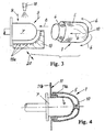
- a piece of tubing 1 of compliant woven or nonwoven material is provided, which material may later be provided with at least one layer of thermoformable plastic, the length L of the piece of tubing 1 being selected in dependence on the length dimension of the finished hollow body member. This length dimension L is understandably dependent on the intended use of the element is intended.
- the piece of tubing 1 of predetermined length is then narrowed at a point 2 between its ends.
- Such narrowing can according to FIG. 2 by twisting a longitudinal section of the hose piece about its longitudinal axis according to the arrow 2a, for example by at least 60 ° - 180 °.
- a rotation causes an automatic narrowing of the hose piece at the point 2.
- the effect of narrowing or twisting exists is that an at least partial preforming of a bottom portion 3 for the later, finished element is formed, the bottom portion is thus closed or has a central hole, as will become clear below.
- two length sections 4 and 5 of the hose piece 1 are formed by the narrowing or twisting.
- a preferred point 2 of the hose piece 1 is located in the longitudinal center of the hose piece, so that two substantially equal length sections 4 and 5 are formed become.
- the next step is after FIG. 3 in that the one longitudinal section 5 is slipped over the other longitudinal section 4 according to the arrows 6, whereby a certain preform of a pot is formed.
- a mold 7, for example a dome is used, on which or on which the double-ply shaped tube piece 1 according to the arrow 8 is pushed.
- the final preform z.
- the outer shape of the molding tool 7 or of the dome corresponds to that inner shape which is to have the finished, tubular element.
- the process steps after the Fig. 1 and 2 can also be combined with each other by the narrowing or twisting takes place when a length section 4 of the hose piece has already been pushed onto the tool 7.
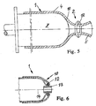
- this cup shape is by application of heat and subsequent cooling in conjunction with the application of a thermoformable plastic material and in conjunction with an already present in the hose piece 1, yielding and thermoformable plastic material secured or stabilized,
- the piece of hose located on the mold is irradiated with heat all around, as it is 9 in FIG. 3 is indicated schematically.
- the heat application can also be done in a different way, for example by internal heating of the tool 7 or in an oven.
- a preferred heating temperature includes a range of about 200 ° C to 400 ° C. This causes the thermoformable plastic material to melt and enclose the non-thermoformable material of the tube piece 1 as a reinforcing inlet. After an appropriate time of heating, the cooling takes place in a suitable manner, so that a composite component is formed.
- this is removed from the mold 7 and can then be fed to its finishing.
- This finishing can consist in that the final length of the hollow body-shaped element 1, for example. is made by trimming and that in the bottom portion 10 of the element a central bore is provided.
- the fabric material or nonwoven material is a hybrid material and consists of a non-thermoformable fiber content of z.
- Example glass fiber or carbon fiber and a thermoformable Foseranteil of thermoplastic or thermosetting fibers, eg. B. polypropylene, Potypropylensulfid or polyester.
- the fabric material or the Vilesmaterial can subsequently, so after its shaping on the mold 7. Still be provided with at least one plastic layer.
- non-thermoformable material is to be understood as being a material whose melting point is so high that this material is used during heat application does not melt the process of the invention.
- thermoformable material is to be understood as meaning that this material is one which becomes molten in the temperature range for heat application given above. This maintains the structural integrity of the non-thermoformable material as a woven or nonwoven fabric during the process, and this material is thus embedded in the thermoformable material to safely achieve a composite component.
- FIG. 4 shows a supplementary process step. It can be seen that an annular connection component 11 is used, which is provided at the non-narrowed end region of the double-layered hose piece 1.
- This connection component 11 has a cylindrical portion 11 a, which is located between the two longitudinal sections 4 and 5 of the hose piece 1 which are folded over one another.
- the connection component has a radial section 11b, for example in the form of a flange, with which the finished element can be fastened in a larger structural unit, for example on a part in an electric drive motor (not shown).
- This connection component can be made of metal or plastic.
- FIG. 5 shows an alternative for narrowing the tube piece at the point 2.
- a ring 12 which may be formed for example as a clip.
- a twisting of the longitudinal section 5 of the hose section 11 is eliminated.
- an axial passage in the later bottom area 10 of the cup-shaped element can be created simultaneously, wherein the diameter of the ring can be selected 12 or the rings of the diameter of the desired axial passage is substantially fixed.
- the ring 12 can, or the rings can be made of plastic or metal.
- a thread knot (not shown), with which a closed bottom region 10 is generally produced.
- FIG. 6 shows a further alternative embodiment of a tubular or cup-shaped element, which is produced by the method according to the invention.
- the mold 7 is omitted in this illustration.
- a sleeve-shaped component 13 is inserted in the bottom region of the double-layered tubular piece 1, such that the center of this component coincides with the longitudinal central axis 14 of the element to be produced.
- This sleeve-shaped component serves to form a special axial passage in the bottom region 10 of the tubular element.
- the sleeve-shaped component 13 can serve, for example, to receive a motor shaft.
- the sleeve-shaped component 13 will advantageously be a bearing bush and consist of a corresponding bearing metal.
- a metal, but also a plastic can be selected.
- the above-mentioned ring 12 (or a plurality of rings) can also be used to narrow the tube piece 1 in the region of the sleeve-shaped component. At the same time is effected by the application of the ring 12 or more rings, that the sleeve-shaped member 13 is secured in position during the manufacturing process of the cup-shaped element.
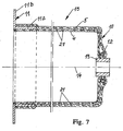
- FIG. 7 shows the example use of an element prepared as described above, in the form of a canned pot 15, used in a wet-running electric motor (not shown) becomes.
- Wet-running motors are known to be used to drive centrifugal pumps.
- FIG. 7 shows that in the bottom portion 10, a component 13 is used as a bearing bush whose central axis coincides with the longitudinal center axis of the canned pot 15 and which is additionally secured with a ring 12 in the bottom portion 10.
- the peripheral wall and the bottom portion of the canned pot formed by the lengths 4 and 5 contain integrated and heat-applied reinforcement formed from the non-thermoformable exemplified fiberglass material of the fabric material or nonwoven material of the length of tubing. This reinforcement is in Fig. 7 indicated by dashed lines and designated 21.
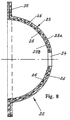
- Fig. 8 shows a so-called separation cap 22, which is used for a so-called magnetic drive, which is electrically operated in a known manner and can also be used to drive centrifugal pumps.
- Such magnetic drives are z. B. in the two U.S. Patents 3,803,432 and 4 043 706 to which a general understanding of these drives is hereby incorporated by reference.
- the separating caps are numbered 15 and 3, respectively.
- the separating cap 22 after Fig. 8 The present patent application, apart from its shape, basically constructed as it in connection with the canned pot 15 after Fig. 7 is explained and made as it is in connection with the FIGS. 1 to 6 is described.
- the separating cap consists of a hollow, substantially a cup shape forming hemispherical wall portion 23 which in the case shown here consists of two wall layers 23a and 23b of z.
- polypropylene has been formed, but which are fused together after the heat application into a single layer, with a central passage 24 and with a circumferential flange portion 25, which may also be omitted.
- the Trennkalotte after their preparation also has an internal reinforcement 26 made of a non-heat moldable material, eg. As glass fiber or carbon fiber, and is thus a composite component.
- hollow body-shaped member produced by the above-described method may be used as a housing part for a variety of purposes.
- housing parts are suitable as head housing parts and / or as unitygeratiusemaschine for multi-stage centrifugal pumps.
Abstract
Description
Die Erfindung betrifft ein Verfahren zum Herstellen eines formstabilen, hohlkörperförmigen Elementes mit einem Bodenbereich.The invention relates to a method for producing a dimensionally stable, hollow-body-shaped element having a bottom region.
Aus der nächstkommenden
Es ist weiterhin allgemein praktizierter Stand der Technik, durch Tiefziehen eines Metalls oder durch Kunststoffspritzgießen ein z. B. rohrförmiges Element mit einem Bodenbereich an seinem einen Ende herzustellen. Ein solches Element kann zum Beispiel als Spaltrohrtopf für einen elektrischen Nasslaüfmotör oder als Trennkalotte in einem elektromagnetischen Antriebsmotor verwendet werden, beispielsweise zum Antreiben einer Kreiselpumpe. Das Element wird in der Regel aus einem Eisenmetall tiefgezogen oder aus Kunststoff spritzgegossen. Eine solche Herstellungsweise ist besonders teuer, weil insbesondere die Werkzeuge zu ihrer Herstellung für die Durchführung des Tiefziehverfahrens bzw. des Spritzgießens außerordentlich hohe Werkzeugkosten verursachen. Diese Kosten sind daher nur dann annehmbar, wenn größere Stückzahlen an Elementen erforderlich sind. Weil jedoch zunehmend auch kleinere Stückzahlen gewünscht werden, zum Beispiel für elektrische Motoren zum Antreiben von in kleineren Mengen benötigten Kreiselpumpen, ist ein Bedarf an einem kostengünstigeren Herstellungsverfahren für das Herstellen von insbesondere Spaltrohrtöpfen und Trennkalotten für elektrische Antriebsmotoren für Kreiselpumpen vorhanden. Des Weiteren weisen Spaltrohrtöpfe und Trennkalotten, wenn sie aus Kunststoff hergestellt sind, oft eine zu geringe mechanische Dauerfestigkeit auf, was zu einem vorzeitigen Verschleiß dieser Hohlkörperelemente und damit zu einem verfrühten Funktionsausfall der Motoren und Aggregate, in welchen diese Elemente eingebaut sind, führt.It is also generally practiced prior art, by deep drawing a metal or by plastic injection molding a z. B. produce tubular element with a bottom portion at one end. Such an element can be used, for example, as a canned pot for an electric wet-air motor or as a separating cap in an electromagnetic drive motor, for example for driving a centrifugal pump. The element is usually deep-drawn from a ferrous metal or injection-molded from plastic. Such a method of production is particularly expensive because, in particular, the tools for their production for carrying out the deep-drawing process or injection molding cause extraordinarily high tooling costs. These costs are therefore acceptable only if larger numbers of elements are required. However, because smaller and smaller numbers of units are increasingly desired, for example, for electric motors for driving centrifugal pumps required in smaller quantities, there is a need for a more cost-effective method of manufacturing especially canned and split calipers for electric drive motors for centrifugal pumps. Furthermore, canned pipes and Trennkalotten when they are made of plastic, often too low a mechanical fatigue strength, resulting in premature wear of these hollow body elements and thus a premature failure of the motors and units, in which these elements are installed leads.
Die Aufgabe der Erfindung besteht darin, ein Verfahren zum Herstellen eines formstabilen, hohlkörperförmigen Elementes mit einem Bodenbereich zur Verfügung zu stellen, welches Verfahren im Vergleich zu herkömmlichen Herstellungsverfahren erhebliche Kostenvorteile für seine Durchführung, insbesondere in Bezug auf kleine Seriengrößen, bietet und welches es erlaubt, Hohlkörperelemente mit erhöhter mechanischer Festigkeit herzustellen.The object of the invention is to provide a method for producing a dimensionally stable, hollow-body-shaped element with a bottom area, which method offers considerable cost advantages for its implementation, in particular with respect to small series sizes, compared with conventional production methods, and which permits To produce hollow body elements with increased mechanical strength.
Die Lösung dieser Aufgabe ist in dem Anspruch 1 angegeben.The solution to this problem is specified in the
Mit dem erfindungsgemäßen Verfahren ist es möglich, auf kostengünstigere Weise als bisher ein formstabiles, z. B. rohrförmiges Element herzustellen, wobei sich das Verfahren besonders für mengenmäßig kleinere Serienherstellung eignet. Das ist dadurch begründet, dass die hohen Kosten für das Anfertigen von Werkzeugformen für entsprechende Tiefzieh- und Spritzgießwerkzeuge entfallen. Des Weiteren ist das erfindungsgemäße Verfahren selbst auf einfache Weise und mit einfachen Mitteln durchführbar, weil nur einfache und meistens bereits vorhandene Werkzeuge verwendet werden können. Ein weiterer Vorteil besteht darin, dass mit dem erfindungsgemäßen Verfahren aus Kunststoff hergestellte formstabile Elemente in Hohlkörperform auch für höhere mechanische Festigkeitsansprüche geeignet sind, so dass solche Elemente z. B. als so genannte Spaltrohrtöpfe oder Trennkalotten für elektrische Motoren, die zum Beispiel zum Antreiben von insbesondere Kreiselpumpen verwendet werden, eingesetzt werden können. Andere Beispiele für die erfindungsgemäß hergestellten Elemente sind Gehäuseteile für viele Zwecke, insbesondere Kopf- und Fußgehäuseteile für mehrstufige Kreiselpumpen.With the method according to the invention, it is possible in a more cost effective manner than previously a dimensionally stable, z. B. tubular element, wherein the method is particularly suitable for quantitatively smaller series production. This is due to the fact that the high cost of making molds for corresponding thermoforming and injection molding omitted. Furthermore, the method according to the invention can be carried out in a simple manner and with simple means, because only simple and mostly existing tools can be used. Another advantage is that dimensionally stable elements made in the form of hollow bodies of the method made of plastic according to the invention are also suitable for higher mechanical strength requirements, so that such elements z. B. as so-called canned tubes or Trennkalotten for electric motors, which are used for example for driving in particular centrifugal pumps, can be used. Other examples of the elements produced according to the invention are housing parts for many purposes, in particular head and Fußgehäuseteile for multi-stage centrifugal pumps.
Das Gewebematerial bzw. das Vliesmaterial ist ein Hybridmaterial, das z. B. Glasfaser als einen nicht warm formbaren Materialanteil und z. B. Polypropylenfaser als einen warm formbaren Materialantell enthält.The fabric material or the nonwoven material is a hybrid material, the z. B. glass fiber as a non-hot mouldable material content and z. B. contains polypropylene fiber as a hot mouldable material.
Das Verengen des auf die erforderliche Länge gebrachten Schlauchstückes an einer gewünschten Stelle kann auf einfache Weise durch Verdrehen des Schlauchstückes in sich um seine Längachse erfolgen, wodurch das Verengen automatisch eintritt. Alternativ kann das Verengen aber auch durch Anbringen eines Ringes oder einer Fadenverknotung an der gewünschten Stelle des Schlauchstückes erfolgen.The narrowing of the length of hose piece brought to a desired location can be done in a simple manner by twisting the hose piece in itself about its longitudinal axis, whereby the narrowing occurs automatically. Alternatively, the narrowing can also be done by attaching a ring or a Fadenverknotung at the desired location of the hose piece.
Als eine vorteilhafte Temperatur zur Durchführung des Erwärmungs- und Abkühlungsschrittes des vorgeformten Schlauchstückes hat sich eine Temperatur von 200° C bis 400° C herausgestellt.As an advantageous temperature for carrying out the heating and cooling step of the preformed piece of tubing, a temperature of 200 ° C to 400 ° C has been found.
In einer vorteilhaffen Ausführung des erfindungsgemäßen Verfahrens kann das Verengen des Schlauchstückes im Bereich seiner Längsmitte durchgeführt werden, wodurch zwei im Wesentlichen gleich lange Längenabschnitte des Schlauchstückes entstehen. Hierbei wird der eine Längenabschnitt über den anderen Längenabschnitt gestülpt, um ein doppellagiges Schlauchstück zu bilden. Dabei kann des Weiteren so vorgegangen werden, dass an dem nicht verengten Endbereich des verengten Schlauchstückes ein ringförmiges Anschlussbauteil mit einem zylindrischen Abschnitt eingesetzt wird, derart, dass sich der zylindrische Abschnitt dieses Bauteiles zwischen den beiden übereinander gestülpten Längenabschnitten des Schlauchstückes befindet.In a vorteilhaffen embodiment of the method according to the invention, the narrowing of the tube piece can be carried out in the region of its longitudinal center, whereby two substantially equal length lengths of the piece of tubing arise. In this case, the one longitudinal section is slipped over the other longitudinal section to form a double-layered piece of hose. In this case, it is also possible to proceed in such a way that an annular connection component having a cylindrical section is used at the non-narrowed end region of the constricted tube piece, such that the cylindrical one can be used Section of this component between the two superimposed lengths of the hose piece is located.
In einer anderen Weitergestaltung kann im Bereich der Verengungsstelle des Schlauchstückes zur Ausbildung eines axialen Durchganges im Bodenbereich eines hohlkörperförmigen Elementes ein hülsenförmiges Bauteil eingesetzt werden, derart, dass das Zentrum dieses Bauteils mit der Längsmittelachse des herzustellenden Elementes zusammen fällt. Dieses Bauteil kann beispielsweise eine Lagerbuchse sein und aus Metall oder Kunststoff bestehen.In another refinement, a sleeve-shaped component can be used in the region of the constriction point of the hose piece to form an axial passage in the bottom area of a hollow body-shaped element, such that the center of this component coincides with the longitudinal center axis of the element to be produced. This component may for example be a bearing bush and made of metal or plastic.
Nach der vorstehend beschriebenen Weise kann insbesondere ein sogenannter Spaltrohrtopf für einen elektrischen Nasslaufmotor hergestellt werden, welcher Motor wiederum zum Antreiben von Kreiselpumpen eingesetzt werden kann. Ein solcher Spaltrohrtopf ist somit ein Verbund-Baüteil und in Bezug auf seine Wandflächen flüssigkeitsdicht und erfüllt im Übrigen aufgrund der entsprechenden Materialauswahl für das Gewebe- oder Vliesmaterial als Verstärkungseinlage auch die geforderten höheren mechanischen Festigkeitswerte. Entsprechendes gilt z. B. auch für eine so genannte Trennkalotte, die üblicherweise für einen Magnetantrieb verwendet wird.According to the manner described above, in particular a so-called canned pot for an electric wet-running motor can be produced, which motor in turn can be used for driving centrifugal pumps. Such a canned pot is thus a composite building part and liquid-tight with respect to its wall surfaces and, moreover, also fulfills the required higher mechanical strength values due to the corresponding material selection for the woven or nonwoven material as reinforcing insert. The same applies z. B. also for a so-called separation calotte, which is usually used for a magnetic drive.
Weitere Vorteile der Erfindung ergeben sich aus den Unteransprüchen und aus der nachstehenden Beschreibung eines Ausführungsbeispieles, welches in den anliegenden Zeichnungen schematisch dargestellt ist. Darin zeigen:
Figur 1- eine Seitenansicht eines Schlauchstückes,
Figur 2- eine Seitenansicht des Schlauchstückes nach dem ersten Verfahrensschritt,
Figur 3- eine Seitenansicht auf das Schlauchstück nach einem weiteren Verfahrensschritt,
Figuren - jeweils einen Axialschnitt zur Darstellung noch weiterer Verfahrensschritte,
Figur 7- einen Axialschnitt durch einen Spaltrohrtopf für einen elektrischen Antriebsmotor, wobei der Spaltrohrtopf gemäß dem erfindungsgemäßen Verfahren herstellbar ist.
- Figur 8
- einen Axialschnitt durch eine Trennkalotte für einen Elektromagnetantrieb, wobei die Trennkalotte gemäß dem erfindungsgemäßen Verfahren herstellbar ist.
- FIG. 1
- a side view of a piece of tubing,
- FIG. 2
- a side view of the hose piece after the first process step,
- FIG. 3
- a side view of the hose piece after a further process step,
- FIGS. 4, 5 and 6
- each an axial section to illustrate still further process steps,
- FIG. 7
- an axial section through a canned pot for an electric drive motor, wherein the canned pot can be produced according to the inventive method.
- FIG. 8
- an axial section through a separating dome for an electromagnetic drive, wherein the separating dome can be produced according to the inventive method.
Zunächst sind die Grundlagen des erfindungsgemäßen Verfahrens anhand der vereinfachten Darstellungen in den
Das Schlauchstück 1 vorbestimmter Länge wird anschließend an einer Stelle 2 zwischen seinen Enden verengt. Ein solches Verengen kann gemäß
Der nächste Verfahrensschritt besteht nach
Nachdem das doppellagig vorgeformte Schlauchstück 1 auf dem Formwerkzeug 7 seine Topfform erhalten hat, wird diese Topfform durch Anwendung von Wärme und anschließendes Abkühlen in Verbindung mit dem Aufbringen eines warm formbaren Kunststoffmaterials und in Verbindung mit einem bereits im Schlauchstück 1 vorhandenen, nachgiebigen und warm formbaren Kunststoffmaterial gesichert bzw. stabilisiert, Hierzu wird das auf dem Formwerkzeug befindliche Schlauchstück mit Wärme rundherum bestrahlt wird, wie es mit 9 in
Nach dem Abkühlen des formstabilisierten Elementes wird dieses von dem Formwerkzeug 7 abgenommen und kann dann seiner Endbearbeitung zugeführt werden. Diese Endbearbeitung kann darin bestehen, dass die endgültige Länge des hohlkörperförmigen Elementes 1 zB. durch Beschneiden hergestellt wird und dass in dem Bodenbereich 10 des Elementes eine zentrale Bohrung vorgesehen wird.After cooling of the dimensionally stabilized element, this is removed from the
Das Gewebematerial oder das Vliesmaterial ist ein Hybridmaterial und besteht es aus einem nicht warm verformbaren Faseranteil aus z. B. Glasfaser oder Kohlefaser und aus einem warm verformbaren Foseranteil aus thermoplastischen oder duroplastischen Fasern, z. B. aus Polypropylen, Potypropylensulfid oder Polyester.The fabric material or nonwoven material is a hybrid material and consists of a non-thermoformable fiber content of z. Example, glass fiber or carbon fiber and a thermoformable Foseranteil of thermoplastic or thermosetting fibers, eg. B. polypropylene, Potypropylensulfid or polyester.
Das Gewebematerial oder das Vilesmaterial kann nachträglich, also nach seiner Formgebung auf dem Formwerkzeug 7. noch mit wenigstens einer Kunststoffschicht versehen werden.The fabric material or the Vilesmaterial can subsequently, so after its shaping on the
Der Begriff "nicht warm formbares Material" ist so zu verstehen, dass es sich hierbei um ein Material handelt, dessen Schmelzpunkt so hoch ist, dass dieses Material während der Wärmeanwendung zur Durchführung des erfindungsgemäßen Verfahrens nicht schmilzt. Dagegen ist der Begriff "warm formbares Material" so zu verstehen, dass es sich bei diesem Material um ein solches handelt, das in dem weiter vorstehend angegebenen Temperaturbereich für die Wärmeanwendung schmelzflüssig ist bzw. wird. Dadurch bleibt der strukturelle Aufbau des nicht warm formbaren Materials als Gewebe oder Vlies während des Verfahrens erhalten und dieses Material wird so zur sicheren Erzielung eines Verbund-Bauteils in dem warm formbaren Material eingebettet.The term "non-thermoformable material" is to be understood as being a material whose melting point is so high that this material is used during heat application does not melt the process of the invention. By contrast, the term "thermoformable material" is to be understood as meaning that this material is one which becomes molten in the temperature range for heat application given above. This maintains the structural integrity of the non-thermoformable material as a woven or nonwoven fabric during the process, and this material is thus embedded in the thermoformable material to safely achieve a composite component.
Während der Wärmeanwendung auf den Vorformling auf dem Formwerkzeug 7 wird vorteilhaft auch eine Druckbelastung auf den Vorformling angewendet, um letztlich einen gut geformten, bezüglich seiner Wände sicher flüssigkeitsundurchlässigen und mechanisch hochfesten Formkörper zu erzielen. Dies kann mit einem mehrteiligen Druckwerkzeug erreicht werden, von dem nur ein Bauteil in
Zusätzlich zum Vorsehen des hülsenförmigen Bauteiles 13 kann auch der vorstehend erwähnte Ring 12 (oder mehrere Ringe) verwendet werden, um das Schlauchstück 1 im Bereich des hülsenförmigen Bauteiles zu verengen. Gleichzeitig wird durch die Anwendung des Ringes 12 oder mehrerer Ringe bewirkt, dass das hülsenförmige Bauteil 13 in seiner Lage auch während des Herstellungsprozesses des topfförmigen Elementes gesichert wird.In addition to providing the sleeve-shaped
Die topfförmige Trennkalotte 22 nach
Das nach dem vorstehend beschriebenen Verfahren hergestellte hohlkörperförmige Element kann des Weiteren auch als Gehäuseteil für die verschiedensten Zwecke verwendet werden. Insbesondere sind solche Gehäuseteile als Kopfgehäuseteile und/oder als Fußgehäuseteile für mehrstufige Kreiselpumpen geeignet.Further, the hollow body-shaped member produced by the above-described method may be used as a housing part for a variety of purposes. In particular, such housing parts are suitable as head housing parts and / or as Fußgehäuseteile for multi-stage centrifugal pumps.
Claims (14)
- A method for the manufacture of a shape-stable, hollow-body-like element with a base region, with the following method steps:a. providing a flexible tube piece from a compliant fabric material or fibre non-woven material,b. narrowing the flexible tube piece in diameter at a location of its length for the at least partial preforming of the base region for the hollow-body-like element,c. preforming the narrowed flexible tube piece into a pot shape by way of attaching this flexible tubing piece onto a forming tool, whose outer shape corresponds to the inner shape of the hollow-body-like element, andd. shape-stabilising the preformed pot-shape of the flexible-tubing piece on the forming tool by way of heating and cooling the flexible-tube piece,characterised in that a hybrid material is used as a fabric material or fibre non-woven material and this hybrid material comprises a fibre share which is not thermoformable and a fibre share which is thermoformable.
- A method according to claim 1, characterised in that the fibre share which is not thermoformable is glass fibre or carbon fibre and that the fibre share which is thermoformable is a polypropylene or a polypropylene sulphide in fibre form.
- A method according to claim 1 or 2, characterised in that the plastic layer which is deposited onto the fabric material or fibre non-woven material is manufactured by way of injecting a heated thermoplastic or duroplastic plastic material onto the hollow-body-like flexible tubing piece and by way of pressure application onto the injected-on plastic material.
- A method according to one of the claims 1 to 3, characterised in that the narrowing of the flexible tubing piece is effected by way of rotating at least one length section of the flexible tubing piece about its longitudinal axis.
- A method according to one of the claims 1 to 3, characterised in that the narrowing of the flexible tubing piece is effected by way of attaching a ring.
- A method according to one of the claims 1 to 3, characterised in that the narrowing of the flexible-tubing piece is effected by way of incorporating a fibre knotting.
- A method according to one of the claims 1 to 6, characterised in that the narrowing of the flexible tubing piece is carried out in the region of its longitudinal middle, by which means two longitudinal sections of the flexible tubing piece arise, and that the one longitudinal section is pushed over the other longitudinal section, in order to form a double-layered flexible tubing piece.
- A method according to claim 1, characterised in that the heating of the hollow-body-like, preformed flexible-tubing piece is carried out at a temperature from 200°C to 400 °C.
- A method according to one of the claims 1 to 7, characterised in that a sleeve-like component is inserted in the region of the narrowing location of the narrowed flexible tubing piece for forming an axial passage in the base region of the element, said insertion being in a manner such that the centre of this sleeve-like component coincides with the longitudinal middle axis of the hollow-body-like element to be manufactured.
- A method according to claim 9, characterised in that as a sleeve-like component, such of metal or plastic is used.
- A method according to claim 8 or 9, characterised in that a bearing bush is used as a sleeve-like component.
- A method according to claim 7, characterised in that an annular connection component with a cylindrical section is applied on the non-narrowed end region of the narrowed flexible tubing piece, in a manner such that this cylindrical section is located between the longitudinal sections of the flexible tubing piece which are pushed over one another.
- The use of the method according to at least one of the claims 1 to 14 for manufacturing a shape-stable, hollow-body-like element with a base region (10), as a canned cap (15) for an electrical wet-running motor.
- The use of the method according to at least one of the claims 1 to 14 for manufacturing a shape-stable, hollow-body-like element with a base region as a separating cap (22) for an electric magnet drive motor.
Applications Claiming Priority (2)
| Application Number | Priority Date | Filing Date | Title |
|---|---|---|---|
| DE102004017418 | 2004-04-08 | ||
| DE102004017418A DE102004017418A1 (en) | 2004-04-08 | 2004-04-08 | Method for producing a dimensionally stable, hollow-body-shaped element with a bottom region and use of such an element |
Publications (3)
| Publication Number | Publication Date |
|---|---|
| EP1584452A2 EP1584452A2 (en) | 2005-10-12 |
| EP1584452A3 EP1584452A3 (en) | 2007-01-17 |
| EP1584452B1 true EP1584452B1 (en) | 2011-11-02 |
Family
ID=34895530
Family Applications (1)
| Application Number | Title | Priority Date | Filing Date |
|---|---|---|---|
| EP05002759A Not-in-force EP1584452B1 (en) | 2004-04-08 | 2005-02-10 | Process for forming a formstable hollowlike element having a bottom and use of such an element. |
Country Status (3)
| Country | Link |
|---|---|
| EP (1) | EP1584452B1 (en) |
| AT (1) | ATE531510T1 (en) |
| DE (1) | DE102004017418A1 (en) |
Families Citing this family (7)
| Publication number | Priority date | Publication date | Assignee | Title |
|---|---|---|---|---|
| CN100462567C (en) * | 2006-05-22 | 2009-02-18 | 上海熊猫机械(集团)有限公司 | Water-cooled energy-saving water pump |
| DE102007045108B4 (en) * | 2007-09-20 | 2009-06-18 | Leichtbau-Zentrum Sachsen Gmbh | Method for the production of wheel rims made of textile hose and wheel rim, made of textile hose |
| EP2040352B2 (en) † | 2007-09-21 | 2014-11-19 | Grundfos Management A/S | Airgap sleeve and manufacturing method thereof |
| EP2342068B1 (en) * | 2008-10-07 | 2015-04-29 | Wilo Se | Method and device for the production of heavy-duty plastic molded parts with a hollow profile |
| PL2607710T3 (en) | 2011-12-23 | 2015-08-31 | Grundfos Holding As | Wet running circulation pump |
| FR2995557A1 (en) * | 2012-09-18 | 2014-03-21 | Aircelle Sa | METHOD FOR MANUFACTURING COMPOSITE PARTS, MANUFACTURING PLANT USING SUCH A METHOD, AND COMPOSITE PARTS THUS MANUFACTURED |
| DE102019134334A1 (en) * | 2019-12-13 | 2021-06-17 | Wilo Se | Canned can for a wet rotor pump and process for its production |
Family Cites Families (8)
| Publication number | Priority date | Publication date | Assignee | Title |
|---|---|---|---|---|
| GB904307A (en) * | 1960-08-17 | 1962-08-29 | Yokohama Rubber Co Ltd | A floating ship-fender |
| DE1217600B (en) * | 1961-06-19 | 1966-05-26 | Continental Gummi Werke Ag | Method and device for the manufacture of roller brackets for air springs |
| US3408439A (en) * | 1965-03-03 | 1968-10-29 | Mansfield Tire And Rubber Comp | Method for shaping reinforced flexible diaphragms |
| CH478650A (en) * | 1969-02-04 | 1969-09-30 | Contraves Ag | Process for the production of a reinforced synthetic resin casing on a mold core |
| US4079755A (en) * | 1976-05-04 | 1978-03-21 | Lans Gerald J V D | Inflatable pipe plug |
| EP0060157A3 (en) * | 1981-02-25 | 1984-08-01 | Albany International Corp. | High pressure shell |
| DE4404235C1 (en) * | 1994-02-10 | 1995-01-05 | Urenco Deutschland Gmbh | Process for producing a can from fibre-composite material |
| DE19625797B4 (en) * | 1995-07-08 | 2005-01-27 | Volkswagen Ag | Method for producing a wheel |
-
2004
- 2004-04-08 DE DE102004017418A patent/DE102004017418A1/en not_active Ceased
-
2005
- 2005-02-10 EP EP05002759A patent/EP1584452B1/en not_active Not-in-force
- 2005-02-10 AT AT05002759T patent/ATE531510T1/en active
Also Published As
| Publication number | Publication date |
|---|---|
| ATE531510T1 (en) | 2011-11-15 |
| EP1584452A2 (en) | 2005-10-12 |
| DE102004017418A1 (en) | 2005-11-03 |
| EP1584452A3 (en) | 2007-01-17 |
Similar Documents
| Publication | Publication Date | Title |
|---|---|---|
| DE4414384C2 (en) | Method of manufacturing a drive shaft | |
| EP1584452B1 (en) | Process for forming a formstable hollowlike element having a bottom and use of such an element. | |
| EP2788173B1 (en) | Wheel made of fiber composites, and production method | |
| EP0352663B1 (en) | Method for manufacturing a bicycle fork, and bicycle fork made by such a method | |
| DE102010009528B4 (en) | Leaf spring made of a fiber composite material with integrated bearing eyes and method for producing the same | |
| EP2511084B1 (en) | Fibre-reinforced plastic node element and method for producing and using same | |
| DE102006031326A1 (en) | Process and assembly to manufacture aircraft skin with integral stringers in composite material using a steel wire removable form core winding | |
| DE102008003974B4 (en) | Method for producing (partially) annular, fiber-reinforced plastic-containing components from FVW semi-finished products | |
| DE102010049563B4 (en) | Method for producing a torsion spring | |
| DE102011011577A1 (en) | Manufacturing torsion bar spring or rolling stabilizer for motor vehicle with tubular cross-section, comprises producing component by braiding and/or wrapping core with fiber bundles and thermal melting of matrix material | |
| DE102014004157B4 (en) | Process for the production of load introduction flanges on fiber-reinforced hollow profiles with thermoplastic matrix | |
| DE823344C (en) | Method for shaping or upsetting or flanging fastening means made of thermoplastics, in particular for footwear | |
| EP2342068A2 (en) | Method and device for the production of heavy-duty plastic molded parts with a hollow profile | |
| DE102015007047B4 (en) | Method and device for producing a pressurizable container | |
| DE10236829B4 (en) | Bearing shell for a ball joint and method for its production | |
| DE102014014296A1 (en) | Hollow profile component made of a fiber-reinforced thermoplastic | |
| WO2014118004A1 (en) | Core and method for producing fibre-reinforced semifinished plastic products | |
| DE102017211625B4 (en) | Method for producing a bearing bush, bushing and handlebar for a suspension of a motor vehicle | |
| DE102012210469A1 (en) | Wheel of motor car e.g. passenger car, has wheel center or wheel disc and/or rim that are reinforced by depositor of metal | |
| DE10258630A1 (en) | Long fiber reinforced thermoplastic component manufacture involves placing fiber preform in tool cavity, introduction of fluid plastic into the open tool and then tool closure of tool | |
| DE4038077C2 (en) | ||
| DE60003284T2 (en) | THERMOPLASTIC BIKE FRAME AND METHOD FOR PRODUCING THE SAME | |
| DE102018129549B9 (en) | Shaping the ends of coil springs | |
| DE102008045380A1 (en) | Method for manufacturing plastic sheathed support that is utilized as cam roller in e.g. patient bed, in medicine technology, involves hardening synthetic resin and producing outer contour of support by post-processing of plastic sheath | |
| EP2159035A2 (en) | Method and device for manufacturing blown hollow plastic bodies with at least one reinforcement element |
Legal Events
| Date | Code | Title | Description |
|---|---|---|---|
| PUAI | Public reference made under article 153(3) epc to a published international application that has entered the european phase |
Free format text: ORIGINAL CODE: 0009012 |
|
| AK | Designated contracting states |
Kind code of ref document: A2 Designated state(s): AT BE BG CH CY CZ DE DK EE ES FI FR GB GR HU IE IS IT LI LT LU MC NL PL PT RO SE SI SK TR |
|
| AX | Request for extension of the european patent |
Extension state: AL BA HR LV MK YU |
|
| PUAL | Search report despatched |
Free format text: ORIGINAL CODE: 0009013 |
|
| AK | Designated contracting states |
Kind code of ref document: A3 Designated state(s): AT BE BG CH CY CZ DE DK EE ES FI FR GB GR HU IE IS IT LI LT LU MC NL PL PT RO SE SI SK TR |
|
| AX | Request for extension of the european patent |
Extension state: AL BA HR LV MK YU |
|
| RIC1 | Information provided on ipc code assigned before grant |
Ipc: B29C 53/14 20060101ALN20061213BHEP Ipc: B29C 69/00 20060101ALI20061213BHEP Ipc: B29C 70/86 20060101ALI20061213BHEP Ipc: B29C 57/00 20060101ALN20061213BHEP Ipc: B29D 22/00 20060101AFI20050707BHEP Ipc: B29C 70/30 20060101ALI20061213BHEP Ipc: F04D 13/06 20060101ALI20061213BHEP Ipc: F04D 13/02 20060101ALI20061213BHEP |
|
| 17P | Request for examination filed |
Effective date: 20070420 |
|
| AKX | Designation fees paid |
Designated state(s): AT BE BG CH CY CZ DE DK EE ES FI FR GB GR HU IE IS IT LI LT LU MC NL PL PT RO SE SI SK TR |
|
| 17Q | First examination report despatched |
Effective date: 20100702 |
|
| GRAP | Despatch of communication of intention to grant a patent |
Free format text: ORIGINAL CODE: EPIDOSNIGR1 |
|
| GRAS | Grant fee paid |
Free format text: ORIGINAL CODE: EPIDOSNIGR3 |
|
| GRAA | (expected) grant |
Free format text: ORIGINAL CODE: 0009210 |
|
| AK | Designated contracting states |
Kind code of ref document: B1 Designated state(s): AT BE BG CH CY CZ DE DK EE ES FI FR GB GR HU IE IS IT LI LT LU MC NL PL PT RO SE SI SK TR |
|
| REG | Reference to a national code |
Ref country code: GB Ref legal event code: FG4D Free format text: NOT ENGLISH |
|
| REG | Reference to a national code |
Ref country code: CH Ref legal event code: EP |
|
| REG | Reference to a national code |
Ref country code: IE Ref legal event code: FG4D |
|
| REG | Reference to a national code |
Ref country code: DE Ref legal event code: R096 Ref document number: 502005012080 Country of ref document: DE Effective date: 20120112 |
|
| REG | Reference to a national code |
Ref country code: NL Ref legal event code: VDEP Effective date: 20111102 |
|
| LTIE | Lt: invalidation of european patent or patent extension |
Effective date: 20111102 |
|
| PG25 | Lapsed in a contracting state [announced via postgrant information from national office to epo] |
Ref country code: LT Free format text: LAPSE BECAUSE OF FAILURE TO SUBMIT A TRANSLATION OF THE DESCRIPTION OR TO PAY THE FEE WITHIN THE PRESCRIBED TIME-LIMIT Effective date: 20111102 Ref country code: IS Free format text: LAPSE BECAUSE OF FAILURE TO SUBMIT A TRANSLATION OF THE DESCRIPTION OR TO PAY THE FEE WITHIN THE PRESCRIBED TIME-LIMIT Effective date: 20120302 |
|
| PG25 | Lapsed in a contracting state [announced via postgrant information from national office to epo] |
Ref country code: GR Free format text: LAPSE BECAUSE OF FAILURE TO SUBMIT A TRANSLATION OF THE DESCRIPTION OR TO PAY THE FEE WITHIN THE PRESCRIBED TIME-LIMIT Effective date: 20120203 Ref country code: SE Free format text: LAPSE BECAUSE OF FAILURE TO SUBMIT A TRANSLATION OF THE DESCRIPTION OR TO PAY THE FEE WITHIN THE PRESCRIBED TIME-LIMIT Effective date: 20111102 Ref country code: SI Free format text: LAPSE BECAUSE OF FAILURE TO SUBMIT A TRANSLATION OF THE DESCRIPTION OR TO PAY THE FEE WITHIN THE PRESCRIBED TIME-LIMIT Effective date: 20111102 Ref country code: PL Free format text: LAPSE BECAUSE OF FAILURE TO SUBMIT A TRANSLATION OF THE DESCRIPTION OR TO PAY THE FEE WITHIN THE PRESCRIBED TIME-LIMIT Effective date: 20111102 Ref country code: PT Free format text: LAPSE BECAUSE OF FAILURE TO SUBMIT A TRANSLATION OF THE DESCRIPTION OR TO PAY THE FEE WITHIN THE PRESCRIBED TIME-LIMIT Effective date: 20120302 Ref country code: NL Free format text: LAPSE BECAUSE OF FAILURE TO SUBMIT A TRANSLATION OF THE DESCRIPTION OR TO PAY THE FEE WITHIN THE PRESCRIBED TIME-LIMIT Effective date: 20111102 |
|
| REG | Reference to a national code |
Ref country code: IE Ref legal event code: FD4D |
|
| PG25 | Lapsed in a contracting state [announced via postgrant information from national office to epo] |
Ref country code: CY Free format text: LAPSE BECAUSE OF FAILURE TO SUBMIT A TRANSLATION OF THE DESCRIPTION OR TO PAY THE FEE WITHIN THE PRESCRIBED TIME-LIMIT Effective date: 20111102 |
|
| PG25 | Lapsed in a contracting state [announced via postgrant information from national office to epo] |
Ref country code: EE Free format text: LAPSE BECAUSE OF FAILURE TO SUBMIT A TRANSLATION OF THE DESCRIPTION OR TO PAY THE FEE WITHIN THE PRESCRIBED TIME-LIMIT Effective date: 20111102 Ref country code: BG Free format text: LAPSE BECAUSE OF FAILURE TO SUBMIT A TRANSLATION OF THE DESCRIPTION OR TO PAY THE FEE WITHIN THE PRESCRIBED TIME-LIMIT Effective date: 20120202 Ref country code: IE Free format text: LAPSE BECAUSE OF FAILURE TO SUBMIT A TRANSLATION OF THE DESCRIPTION OR TO PAY THE FEE WITHIN THE PRESCRIBED TIME-LIMIT Effective date: 20111102 Ref country code: DK Free format text: LAPSE BECAUSE OF FAILURE TO SUBMIT A TRANSLATION OF THE DESCRIPTION OR TO PAY THE FEE WITHIN THE PRESCRIBED TIME-LIMIT Effective date: 20111102 Ref country code: SK Free format text: LAPSE BECAUSE OF FAILURE TO SUBMIT A TRANSLATION OF THE DESCRIPTION OR TO PAY THE FEE WITHIN THE PRESCRIBED TIME-LIMIT Effective date: 20111102 Ref country code: CZ Free format text: LAPSE BECAUSE OF FAILURE TO SUBMIT A TRANSLATION OF THE DESCRIPTION OR TO PAY THE FEE WITHIN THE PRESCRIBED TIME-LIMIT Effective date: 20111102 |
|
| BERE | Be: lapsed |
Owner name: GRUNDFOS A/S Effective date: 20120228 |
|
| PG25 | Lapsed in a contracting state [announced via postgrant information from national office to epo] |
Ref country code: RO Free format text: LAPSE BECAUSE OF FAILURE TO SUBMIT A TRANSLATION OF THE DESCRIPTION OR TO PAY THE FEE WITHIN THE PRESCRIBED TIME-LIMIT Effective date: 20111102 |
|
| PLBE | No opposition filed within time limit |
Free format text: ORIGINAL CODE: 0009261 |
|
| STAA | Information on the status of an ep patent application or granted ep patent |
Free format text: STATUS: NO OPPOSITION FILED WITHIN TIME LIMIT |
|
| PG25 | Lapsed in a contracting state [announced via postgrant information from national office to epo] |
Ref country code: MC Free format text: LAPSE BECAUSE OF NON-PAYMENT OF DUE FEES Effective date: 20120229 |
|
| REG | Reference to a national code |
Ref country code: CH Ref legal event code: PL |
|
| 26N | No opposition filed |
Effective date: 20120803 |
|
| PG25 | Lapsed in a contracting state [announced via postgrant information from national office to epo] |
Ref country code: CH Free format text: LAPSE BECAUSE OF NON-PAYMENT OF DUE FEES Effective date: 20120229 Ref country code: LI Free format text: LAPSE BECAUSE OF NON-PAYMENT OF DUE FEES Effective date: 20120229 |
|
| REG | Reference to a national code |
Ref country code: DE Ref legal event code: R097 Ref document number: 502005012080 Country of ref document: DE Effective date: 20120803 |
|
| PG25 | Lapsed in a contracting state [announced via postgrant information from national office to epo] |
Ref country code: BE Free format text: LAPSE BECAUSE OF NON-PAYMENT OF DUE FEES Effective date: 20120228 |
|
| REG | Reference to a national code |
Ref country code: AT Ref legal event code: MM01 Ref document number: 531510 Country of ref document: AT Kind code of ref document: T Effective date: 20120210 |
|
| PG25 | Lapsed in a contracting state [announced via postgrant information from national office to epo] |
Ref country code: ES Free format text: LAPSE BECAUSE OF FAILURE TO SUBMIT A TRANSLATION OF THE DESCRIPTION OR TO PAY THE FEE WITHIN THE PRESCRIBED TIME-LIMIT Effective date: 20120213 |
|
| PG25 | Lapsed in a contracting state [announced via postgrant information from national office to epo] |
Ref country code: AT Free format text: LAPSE BECAUSE OF NON-PAYMENT OF DUE FEES Effective date: 20120210 Ref country code: FI Free format text: LAPSE BECAUSE OF FAILURE TO SUBMIT A TRANSLATION OF THE DESCRIPTION OR TO PAY THE FEE WITHIN THE PRESCRIBED TIME-LIMIT Effective date: 20111102 |
|
| PG25 | Lapsed in a contracting state [announced via postgrant information from national office to epo] |
Ref country code: TR Free format text: LAPSE BECAUSE OF FAILURE TO SUBMIT A TRANSLATION OF THE DESCRIPTION OR TO PAY THE FEE WITHIN THE PRESCRIBED TIME-LIMIT Effective date: 20111102 |
|
| PG25 | Lapsed in a contracting state [announced via postgrant information from national office to epo] |
Ref country code: LU Free format text: LAPSE BECAUSE OF NON-PAYMENT OF DUE FEES Effective date: 20120210 |
|
| PG25 | Lapsed in a contracting state [announced via postgrant information from national office to epo] |
Ref country code: HU Free format text: LAPSE BECAUSE OF FAILURE TO SUBMIT A TRANSLATION OF THE DESCRIPTION OR TO PAY THE FEE WITHIN THE PRESCRIBED TIME-LIMIT Effective date: 20050210 |
|
| REG | Reference to a national code |
Ref country code: FR Ref legal event code: PLFP Year of fee payment: 12 |
|
| REG | Reference to a national code |
Ref country code: FR Ref legal event code: PLFP Year of fee payment: 13 |
|
| REG | Reference to a national code |
Ref country code: FR Ref legal event code: PLFP Year of fee payment: 14 |
|
| PGFP | Annual fee paid to national office [announced via postgrant information from national office to epo] |
Ref country code: GB Payment date: 20220221 Year of fee payment: 18 Ref country code: DE Payment date: 20220221 Year of fee payment: 18 |
|
| PGFP | Annual fee paid to national office [announced via postgrant information from national office to epo] |
Ref country code: IT Payment date: 20220228 Year of fee payment: 18 Ref country code: FR Payment date: 20220221 Year of fee payment: 18 |
|
| REG | Reference to a national code |
Ref country code: DE Ref legal event code: R082 Ref document number: 502005012080 Country of ref document: DE |
|
| REG | Reference to a national code |
Ref country code: DE Ref legal event code: R119 Ref document number: 502005012080 Country of ref document: DE |
|
| GBPC | Gb: european patent ceased through non-payment of renewal fee |
Effective date: 20230210 |
|
| PG25 | Lapsed in a contracting state [announced via postgrant information from national office to epo] |
Ref country code: GB Free format text: LAPSE BECAUSE OF NON-PAYMENT OF DUE FEES Effective date: 20230210 |
|
| PG25 | Lapsed in a contracting state [announced via postgrant information from national office to epo] |
Ref country code: IT Free format text: LAPSE BECAUSE OF NON-PAYMENT OF DUE FEES Effective date: 20230210 Ref country code: GB Free format text: LAPSE BECAUSE OF NON-PAYMENT OF DUE FEES Effective date: 20230210 Ref country code: FR Free format text: LAPSE BECAUSE OF NON-PAYMENT OF DUE FEES Effective date: 20230228 Ref country code: DE Free format text: LAPSE BECAUSE OF NON-PAYMENT OF DUE FEES Effective date: 20230901 |