EP2689632B1 - Terminal mobile et procédé d'interfaçage de ce terminal mobile - Google Patents
Terminal mobile et procédé d'interfaçage de ce terminal mobile Download PDFInfo
- Publication number
- EP2689632B1 EP2689632B1 EP12760978.2A EP12760978A EP2689632B1 EP 2689632 B1 EP2689632 B1 EP 2689632B1 EP 12760978 A EP12760978 A EP 12760978A EP 2689632 B1 EP2689632 B1 EP 2689632B1
- Authority
- EP
- European Patent Office
- Prior art keywords
- connector
- pin
- accessory
- battery
- pins
- Prior art date
- Legal status (The legal status is an assumption and is not a legal conclusion. Google has not performed a legal analysis and makes no representation as to the accuracy of the status listed.)
- Not-in-force
Links
Images


Classifications
-
- H—ELECTRICITY
- H02—GENERATION; CONVERSION OR DISTRIBUTION OF ELECTRIC POWER
- H02J—CIRCUIT ARRANGEMENTS OR SYSTEMS FOR SUPPLYING OR DISTRIBUTING ELECTRIC POWER; SYSTEMS FOR STORING ELECTRIC ENERGY
- H02J7/00—Circuit arrangements for charging or depolarising batteries or for supplying loads from batteries
- H02J7/00047—Circuit arrangements for charging or depolarising batteries or for supplying loads from batteries with provisions for charging different types of batteries
-
- G—PHYSICS
- G06—COMPUTING; CALCULATING OR COUNTING
- G06F—ELECTRIC DIGITAL DATA PROCESSING
- G06F13/00—Interconnection of, or transfer of information or other signals between, memories, input/output devices or central processing units
- G06F13/38—Information transfer, e.g. on bus
- G06F13/382—Information transfer, e.g. on bus using universal interface adapter
-
- H—ELECTRICITY
- H02—GENERATION; CONVERSION OR DISTRIBUTION OF ELECTRIC POWER
- H02J—CIRCUIT ARRANGEMENTS OR SYSTEMS FOR SUPPLYING OR DISTRIBUTING ELECTRIC POWER; SYSTEMS FOR STORING ELECTRIC ENERGY
- H02J7/00—Circuit arrangements for charging or depolarising batteries or for supplying loads from batteries
- H02J7/00032—Circuit arrangements for charging or depolarising batteries or for supplying loads from batteries characterised by data exchange
- H02J7/00038—Circuit arrangements for charging or depolarising batteries or for supplying loads from batteries characterised by data exchange using passive battery identification means, e.g. resistors or capacitors
- H02J7/00041—Circuit arrangements for charging or depolarising batteries or for supplying loads from batteries characterised by data exchange using passive battery identification means, e.g. resistors or capacitors in response to measured battery parameters, e.g. voltage, current or temperature profile
-
- H—ELECTRICITY
- H02—GENERATION; CONVERSION OR DISTRIBUTION OF ELECTRIC POWER
- H02J—CIRCUIT ARRANGEMENTS OR SYSTEMS FOR SUPPLYING OR DISTRIBUTING ELECTRIC POWER; SYSTEMS FOR STORING ELECTRIC ENERGY
- H02J7/00—Circuit arrangements for charging or depolarising batteries or for supplying loads from batteries
- H02J7/0013—Circuit arrangements for charging or depolarising batteries or for supplying loads from batteries acting upon several batteries simultaneously or sequentially
-
- H—ELECTRICITY
- H02—GENERATION; CONVERSION OR DISTRIBUTION OF ELECTRIC POWER
- H02J—CIRCUIT ARRANGEMENTS OR SYSTEMS FOR SUPPLYING OR DISTRIBUTING ELECTRIC POWER; SYSTEMS FOR STORING ELECTRIC ENERGY
- H02J7/00—Circuit arrangements for charging or depolarising batteries or for supplying loads from batteries
- H02J7/0042—Circuit arrangements for charging or depolarising batteries or for supplying loads from batteries characterised by the mechanical construction
- H02J7/0044—Circuit arrangements for charging or depolarising batteries or for supplying loads from batteries characterised by the mechanical construction specially adapted for holding portable devices containing batteries
-
- H—ELECTRICITY
- H02—GENERATION; CONVERSION OR DISTRIBUTION OF ELECTRIC POWER
- H02J—CIRCUIT ARRANGEMENTS OR SYSTEMS FOR SUPPLYING OR DISTRIBUTING ELECTRIC POWER; SYSTEMS FOR STORING ELECTRIC ENERGY
- H02J7/00—Circuit arrangements for charging or depolarising batteries or for supplying loads from batteries
- H02J7/0042—Circuit arrangements for charging or depolarising batteries or for supplying loads from batteries characterised by the mechanical construction
- H02J7/0045—Circuit arrangements for charging or depolarising batteries or for supplying loads from batteries characterised by the mechanical construction concerning the insertion or the connection of the batteries
-
- H—ELECTRICITY
- H02—GENERATION; CONVERSION OR DISTRIBUTION OF ELECTRIC POWER
- H02J—CIRCUIT ARRANGEMENTS OR SYSTEMS FOR SUPPLYING OR DISTRIBUTING ELECTRIC POWER; SYSTEMS FOR STORING ELECTRIC ENERGY
- H02J7/00—Circuit arrangements for charging or depolarising batteries or for supplying loads from batteries
- H02J7/0047—Circuit arrangements for charging or depolarising batteries or for supplying loads from batteries with monitoring or indicating devices or circuits
-
- G—PHYSICS
- G06—COMPUTING; CALCULATING OR COUNTING
- G06F—ELECTRIC DIGITAL DATA PROCESSING
- G06F1/00—Details not covered by groups G06F3/00 - G06F13/00 and G06F21/00
- G06F1/26—Power supply means, e.g. regulation thereof
-
- G—PHYSICS
- G06—COMPUTING; CALCULATING OR COUNTING
- G06F—ELECTRIC DIGITAL DATA PROCESSING
- G06F11/00—Error detection; Error correction; Monitoring
- G06F11/30—Monitoring
- G06F11/34—Recording or statistical evaluation of computer activity, e.g. of down time, of input/output operation ; Recording or statistical evaluation of user activity, e.g. usability assessment
- G06F11/3466—Performance evaluation by tracing or monitoring
- G06F11/3485—Performance evaluation by tracing or monitoring for I/O devices
-
- H—ELECTRICITY
- H02—GENERATION; CONVERSION OR DISTRIBUTION OF ELECTRIC POWER
- H02J—CIRCUIT ARRANGEMENTS OR SYSTEMS FOR SUPPLYING OR DISTRIBUTING ELECTRIC POWER; SYSTEMS FOR STORING ELECTRIC ENERGY
- H02J2310/00—The network for supplying or distributing electric power characterised by its spatial reach or by the load
- H02J2310/10—The network having a local or delimited stationary reach
- H02J2310/20—The network being internal to a load
- H02J2310/22—The load being a portable electronic device
-
- H—ELECTRICITY
- H02—GENERATION; CONVERSION OR DISTRIBUTION OF ELECTRIC POWER
- H02J—CIRCUIT ARRANGEMENTS OR SYSTEMS FOR SUPPLYING OR DISTRIBUTING ELECTRIC POWER; SYSTEMS FOR STORING ELECTRIC ENERGY
- H02J3/00—Circuit arrangements for ac mains or ac distribution networks
- H02J3/008—Circuit arrangements for ac mains or ac distribution networks involving trading of energy or energy transmission rights
-
- H—ELECTRICITY
- H04—ELECTRIC COMMUNICATION TECHNIQUE
- H04M—TELEPHONIC COMMUNICATION
- H04M1/00—Substation equipment, e.g. for use by subscribers
- H04M1/02—Constructional features of telephone sets
- H04M1/0202—Portable telephone sets, e.g. cordless phones, mobile phones or bar type handsets
- H04M1/026—Details of the structure or mounting of specific components
- H04M1/0274—Details of the structure or mounting of specific components for an electrical connector module
-
- H—ELECTRICITY
- H04—ELECTRIC COMMUNICATION TECHNIQUE
- H04M—TELEPHONIC COMMUNICATION
- H04M1/00—Substation equipment, e.g. for use by subscribers
- H04M1/72—Mobile telephones; Cordless telephones, i.e. devices for establishing wireless links to base stations without route selection
- H04M1/724—User interfaces specially adapted for cordless or mobile telephones
- H04M1/72403—User interfaces specially adapted for cordless or mobile telephones with means for local support of applications that increase the functionality
- H04M1/72409—User interfaces specially adapted for cordless or mobile telephones with means for local support of applications that increase the functionality by interfacing with external accessories
Definitions
- the present invention relates to a mobile terminal and an interface method thereof. More particularly, the present invention relates to a mobile terminal and an interface method thereof for connecting external devices, such as an adapter, a Universal Serial Bus (USB) cable, a docking station, an accessory, and the like, to the mobile terminal
- external devices such as an adapter, a Universal Serial Bus (USB) cable, a docking station, an accessory, and the like
- a mobile terminal may be a smart phone, a Personal Digital Assistant (PDA), a video game machine, a Digital Multimedia Broadcasting (DMB) receiver, a Motion Pictures Expert Group (MPEG) Audio Layer-3 (MP3) player, a camera, and the like.
- the mobile terminal needs a charging connector for charging a battery.
- the mobile terminal may include a connector for exchanging data with the external device.
- the mobile terminal may include various connectors according to a type thereof.
- the mobile terminal needs to include a low voltage charging connector and a high voltage charging connector in consideration of a charging time and capacity of a battery.
- the mobile terminal needs to include various types of connectors, such as an audio input/output connector and a video input/output connector.
- an extension request if the mobile terminal includes various types of connectors, an external appearance thereof may look poor.
- US2007/145945 A1 discloses a method and apparatus to authenticate a battery charging device.
- GB2389429 A discloses an electronic device for detecting and identifying an electronic accessory.
- WO00/65445 A1 discloses a system and method for detecting an accessory device connected to a portable computer.
- an aspect of the present invention is to provide a mobile terminal for implementing various interfaces by one connector and a method thereof.
- Another aspect of the present invention is to provide a mobile terminal for recognizing a type of an external device connected to one connector.
- a mobile terminal includes a battery, a connector including a pin for data communication and first and second power pins for charging the battery, a memory configured to store a reference voltage indicating a dedicated adapter of the battery, and a controller configured to recognize an external device connected with the connector as the dedicated adapter when a voltage is input from the first and second power pins and a voltage input from the pin for data communication is the reference voltage, and to charge the battery by power input to the first and second power pins; and to recognize, when a voltage is input from the first and second power pins and the voltage input from the pin for data communication is not the reference voltage, the external device connected with the connector as a non-dedicated charger and to determine whether it is possible to charge the battery using the non-dedicated charger, and to charge the battery if it is determined that it is possible to charge the battery using the non-dedicated charger; and wherein the determining of whether it is possible to charge the battery using the non-dedicated charger includes
- the connector may further comprise a battery pin for receiving power during a process or development, a jig on pin for reporting power reception from the first and second power pins to an exterior, and a pin for transmitting and receiving a testing signal.
- a mobile terminal includes a connector including a pin for detecting an accessory and a pin for identifying the accessory, a memory for storing a reference table and for identifying the accessory, and a controller for comparing a voltage input from the pin and for identifying the accessory with the reference table when a voltage input from the pin for detecting the accessory changes to recognize a type of an accessory connected with the connector.
- an interface method of a mobile terminal including a connector with a pin for data communication and first and second power pins for charging the battery of the mobile terminal includes determining whether a voltage input from the pin for data communication is a predefined reference voltage when a voltage is input from the first and second power pins, recognizing an external device connected with the connector as a dedicated adapter of a battery when the voltage input from the pin for data communication is the predefined reference voltage, and charging the battery with power input from the first and second power pins when the external device connected with the connector is recognized as the dedicated adapter of the battery; and recognizing, when a voltage is input from the first and second power pins and the voltage input from the pin for data communication is not the reference voltage, the external device connected with the connector as a non-dedicated charger and determining whether it is possible to charge the battery using the non-dedicated charger, and charging the battery if it is determined that it is possible to charge the battery using the non-dedicated charger; and wherein
- Exemplary embodiments of the present invention may implement various interfaces by one connector and recognize a type of an external device connected to the connector. Moreover, exemplary embodiments of the present invention may use one connector as a testing port from a developing stage of a product to a production stage thereof and various types of adaptors may connect with one connector to charge a battery. Exemplary embodiments of the present invention have an effect that consumers may connect various accessories to the mobile terminal to use it.
- Exemplary embodiments of the present invention provide a mobile terminal and an interface method thereof for connecting external devices, such as an adapter, a Universal Serial Bus (USB) cable, a docking station, an accessory, and the like, to the mobile terminal.
- external devices such as an adapter, a Universal Serial Bus (USB) cable, a docking station, an accessory, and the like.
- USB Universal Serial Bus
- FIGs. 1A through 10 discussed below, and the various exemplary embodiments used to describe the principles of the present disclosure in this patent document are by way of illustration only and should not be construed in any way that would limit the scope of the disclosure. Those skilled in the art will understand that the principles of the present disclosure may be implemented in any suitably arranged communications system.
- the terms used to describe various embodiments are exemplary. It should be understood that these are provided to merely aid the understanding of the description, and that their use and definitions in no way limit the scope of the invention. Terms first, second, and the like are used to differentiate between objects having the same terminology and are in no way intended to represent a chronological order, unless where explicitly state otherwise.
- a set is defined as a non-empty set including at least one element.
- FIG. 1A is an elevated view illustrating a male connector according to an exemplary embodiment of the present invention.
- FIG. 1B is a plan view illustrating a male connector according to an exemplary embodiment of the present invention.
- a male connector 10 may include a housing 11, a pin positioning portion 12, a plurality of pins 13, elastic portions 14, and a frame 15.
- the pin positioning portion 12 is disposed inside the housing 11.
- the plurality of pins 13 are disposed in a plurality of grooves 12a that are formed at the pin positioning portion 12.
- the elastic portions 14 are disposed at both sides of the housing 11.
- the frame 15 supports the housing 11.
- a front surface of the housing 11 is open such that the housing 11 connects with a female connector.
- the pin positioning portion 12 is disposed inside the housing 11. Furthermore, the housing 11 forms a space 11a therein such that a pin positioning portion of a female connector, to be described later, may be inserted in the housing 11 to contact with the pin positioning portion 12 of the mail connector 10 side.
- the plurality of pins 13 are disposed in a plurality of grooves 12a, which are formed at the pin positioning portion 12.
- the number of the plurality of grooves 12a may be thirty. However, the number of the grooves 12a is not limited thereto but may be modified by design.
- the pins 13 may be disposed in the plurality of grooves 12a, but maybe disposed in some of them as shown in FIG. 1A . In other words, the number of the pins 13 may be determined according to utilization of the male connector 10. For example, if a cable including the male connector 10 is limited only for data communication, it is unnecessary to dispose pins 13 in all of the grooves 12a. That is, it would be sufficient to dispose pins 13 in only corresponding grooves 12a.
- a plurality of pins 13 have elasticity and partially protrude from the grooves 12a to an exterior, as shown in FIG. 1A .
- a pin positioning portion of a female connector side adheres tightly to a pin of a female connector side.
- the elastic portions 14 enable the male connector 10 to be tightly inserted in a female connector.
- the elastic portions 14 are disposed in grooves (not shown) formed at both sides of the housing 11 and partially protrude to the outside, as shown in FIG. 1A and FIG. 1B .
- FIG. 2A is a perspective view illustrating a female connector according to an exemplary embodiment of the present invention.
- FIG. 2B is an elevated view illustrating a female connector according to an exemplary embodiment of the present invention.
- FIG. 2C is a fragmentary sectional view illustrating a female connector taken along dotted line A-A' according to an exemplary embodiment of the present invention.
- a female connector 20 may include a housing 21, a pin positioning portion 22, and a plurality of pins 23.
- the pin positioning portion 22 is disposed inside the housing 21.
- the plurality of pins 23 are disposed in a plurality of grooves 22a which are formed at the pin positioning portion 22.
- the housing 21 forms a space 21a therein and a front surface thereof is open such that the housing 11 of the male connector 10 may be inserted in the housing 21 of the female connector 20. Furthermore, as shown in FIG. 2B , grooves 21b are formed at both inner sides of the housing 21. In this case, the elastic portions 14 are inserted in the grooves 21b. As previously illustrated, the elastic portions 14 are inserted in the grooves 21b. Accordingly, unless a user pulls out the male connector 10, the male connector 10 is tightly inserted in the female connector 20.
- the plurality of pins 23 are disposed in a plurality of grooves 22a, which are formed at the pin positioning portion 22.
- the number of a plurality of grooves 22a is the same as that of a plurality of grooves 12a.
- Pins 23 may be disposed in the plurality of grooves 22a, as shown in FIG. 2B , or in some of grooves 22a.
- a mobile terminal mounts the female connector 20 rather than the male connector 10. Consequently, for extension of an interface, pins are disposed in all of a plurality of grooves 22a.
- the plurality of pins 23 are disposed inside the pin positioning portion 22. When the housing 11 of the male connector 10 is inserted into the housing 21 of the female connector 20, the plurality of pins 23 contact with the plurality of pins 13.
- Table 1 below illustrates functions of pins according to an exemplary embodiment of the present invention. As listed in Table 1, the number of the pins is thirty. All or some of the pins are disposed at the connectors 10 or 20.
- Pin No. means a location of a pin in a connector. A first pin is located in a groove formed at a rightmost side of the pin positioning portion 12 or 22. A pin having a Pin No. of a thirtieth pin is located in a groove formed at a leftmost side of the pin positioning portion 12 or 22.
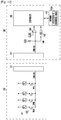
- FIG. 3 is a block diagram illustrating an adapter and a mobile terminal according to an exemplary embodiment of the present invention.
- an adapter 30 may include a plug 31, a converter 32, a connector 33, and a boost circuit 34.
- the plug 31 connects with an outlet that supplies an Alternating Current (AC) power.
- the converter 32 converts the AC power input from the plug 31 into a Direct Current (DC) power (e.g., 5V/2A).
- the connector 33 includes the first, second, third, fourth, seventh, and eighth pins.
- the boost circuit 34 boosts the DC power input from the converter 32 to, for example, 1.16V and outputs the boosted voltage to the third and fourth pins.
- the boost circuit 34 boosts the DC power to a Ground (GND) and outputs the boosted power to the first and second pins.
- the converted DC power from the converter 32 bypasses the seventh and eighth pins.
- the adapter 30 may be used for charging large capacity.
- the converter 32 may convert AC power into, for example, 12V/2A, 12V/5A for charging large capacity, and output converted power to twelfth and thirteenth pins being pins for charging large capacity instead of the seventh and eighth pins.
- the adapter 30 may further include a converter for charging large capacity as well as the converter 32.
- the converter for charging large capacity may be connected with twelfth and thirteenth pins.
- the adapter 30 may be used as a data cable capable of performing data communication between two devices. As a result, the adapter 30 may transmit and receive data through the third and fourth pins of the connector 33.
- a mobile terminal 40 may include a connector 41, a battery 42, a memory 44, and a controller 43.
- the controller 43 recognizes a type of an external device connected to the connector 41 and charges the battery based on the recognized information.
- the connector 41 may include all of thirty pins for extension of an interface.
- the controller 43 determines whether a differential signal is input through USB D+ and D- lines connected to the third and fourth pins, respectively. If the differential signal is not input, the controller 43 recognizes a connected external device as an adapter. If the differential signal is input, the controller 43 recognizes the external device as a USB data cable with a charging function. If charging power input from the seventh and eighth pins is in the range of rated power, for example, from 5 W to 20 W, the controller 43 charges the battery 42. On the other hand, if the charging power input from the seventh and eighth pins is beyond the range of rated power, the controller 43 does not charge the battery 42.
- VBUS Voltage BUS
- the controller 43 recognizes that a charging time is long and does not charge the battery 42. If the input charging power is greater than 5W, the controller 43 recognizes that the battery life shortens due to overcharging and does not charge the battery 42.
- the controller 43 determines whether a connected adapter is a dedicated adapter suitable for rated power of the mobile terminal 40. As the determined result, if the connected adapter is the dedicated adapter, the controller 43 charges the battery 42. If the connected adapter is a non-dedicated adapter, the controller 43 does not charge the battery 42. In the foregoing procedure, if the external device is recognized as the adapter, the controller 43 determines a voltage of USB D+ and D- lines. If the determined voltage is, for example, 1.16V in consideration of a set error range, the controller 43 recognizes that the connected adapter is the dedicated adapter. Here, a reference voltage 1.16V is stored in a memory 44.
- the controller 43 compares a voltage of USB D+ and D- lines with the reference voltage stored in the memory 44. If the voltage of USB D+ and D- lines is identical with the reference voltage, the controller 43 recognizes that an adapter connected to the connector 41 is a dedicated adapter. On the other hand, if the determined voltage is not 1.16V, the controller 43 recognizes that the connected adapter is the non-dedicated adapter and does not charge the battery 42. Although the connected adapter is the non-dedicated adapter, the controller 43 may also charge the battery 42. If charging power input from the seventh and eighth pins is in the range of rated power, the controller 43 may charge the battery 42.
- the controller 43 may include a charging circuit that reduces or increases a voltage or an electric current to charge the battery 42.
- the charging circuit may be included in the adapter 30 instead of the mobile terminal 40.
- Such an adapter refers to a charger distinguished from an adapter without the charging circuit.
- the controller 43 may charge the battery 42 within a short time using charging power input from the twelfth and thirteenth pins. However, as previously illustrated, for example, when the charging power is equal to or greater than 30 W to excessively charge the battery 42, the controller 43 may reduce a voltage or an electric current.
- the controller 43 may receive power from ninth and tenth pins. Since the received power is used to manufacture or develop the mobile terminal 40, it cannot charge the battery 42. When the controller 43 receives power from the ninth and tenth pins, it outputs a signal indicating that the mobile terminal 40 is under testing to an external device through a fifth pin. Furthermore, when the mobile terminal 40 is under testing, the controller 43 may transmit and receive a Universal Asynchronous Receiver/Transmitter (UART) signal being a testing signal through twentieth and twenty- first pins.
- UART Universal Asynchronous Receiver/Transmitter
- FIG. 4 is a flowchart illustrating an interface method of a mobile terminal according to an exemplary embodiment of the present invention.
- a controller 43 determines whether a voltage is applied through a VBUS line in step 51. If it is determined in step 51 that the voltage is applied through a VBUS line, the controller 43 determines whether data (differential signal) is input through a D line (USB D+ and D- lines) in step 52. If it is determined in step 52 that the data is input through a D line, the controller 43 recognizes an external device connected to a connector 41 as a USB data cable in step 53, and the process proceeds to step 54. The controller 43 determines whether it is possible to charge the battery 42 in step 54. Here, whether it is possible to charge the battery 42 was described earlier. Accordingly, a description thereof is omitted. If it is determined in step 54 that it is possible to charge the battery 42, the controller 43 charges the battery 42 in step 58.
- step 52 if it is determined in step 52 that the data is not input through a D line, the controller 43 recognizes the external device connected to the connector 41 as an adapter in step 55, and the process proceeds to step 56.
- the controller 43 determines whether a voltage of a D line is a reference voltage, for example, 1.16V in step 56. If it is determined in step 56 that the voltage of the D line is the reference voltage, the controller 43 recognizes the connected adapter as a dedicated adapter in step 57 and charges the battery 42 in step 58.
- step 56 if it is determined in step 56 that the voltage of the D line is not the reference voltage, the controller 43 recognizes the connected adapter as a non-dedicated adapter in step 59, and the process proceeds to step 60.
- the controller 43 determines whether it is possible to charge the battery 42 in step 60. If it is determined in step 60 that it is possible to charge the battery 42, the controller 43 charges the battery 42 in step 58.
- FIG. 5 is a block diagram illustrating an accessory and a mobile terminal according to an exemplary embodiment of the present invention.
- an accessory 60 may include a connector 61 and an accessory IDentification Resistor 62 (RID).
- the accessory 60 may increase or change functions and effects of the mobile terminal 70.
- the accessory 60 may include an earphone, a headphone, a camera, a keypad, a mouse, a docking station, a data cable, a data cable with a charging function, an adapter, a charger, an external hard disk, or a USB memory.
- the connector 61 may include thirteenth and fourteenth pins.
- the thirteenth pin connects with a ground through the accessory identification resistor 62 (RID).
- the fourteenth pin directly connects with the ground.
- the connector 61 may include at least one pin as well as the foregoing pins.
- the connector 61 when the accessory 60 is an earphone, the connector 61 further includes twenty-seventh and twenty-eighth pins.
- the connector 61 When the accessory 60 is a camera, the connector 61 further includes third and fourth pins.
- the connector 61 When it is necessary to supply power to the accessory 60, the connector 61 further includes first, second, and sixth pins.
- the accessory identification resistor 62 has different resistances depending on the type of accessory. For example, the resistances of the accessory identification resistor 62 may be listed in a following Table 2.
- a mobile terminal 70 may include a connector 71, a memory 72, a comparator 73, an Analog to Digital Converter (ADC) 78, and a controller 74.
- the controller 74 recognizes a type of an external device connected to the connector 71 and may include all of thirty pins for extension of an interface.
- the controller 71 recognizes that the accessory 60 connects with the connector 71.
- the accessory detection line connects the controller 71 to a fourteenth pin and Vcc.
- a negative (-) input terminal of the comparator 73 connects with a thirteen pin and a pull-up voltage (e.g., 3.3V) through a pull-up resistor (e.g., of 10 K ⁇ ).
- a positive (+) terminal of the comparator 73 connects with a reference voltage (e.g., 3.15V).
- the comparator 73 compares a voltage (3.3V or VRID) input from the negative (-) input terminal with the reference voltage input from the positive (+) terminal.
- the comparator 73 When the input voltage (3.3V or VRID) is less than the reference voltage, the comparator 73 outputs a high level signal. When the input voltage (3.3V or VRID) is equal to or greater than the reference voltage, the comparator 73 outputs a low-level signal.
- VRID means a voltage across the identification resistor 62 (RID).
- the controller 71 compares a voltage input from an accessory identification line 76 connected to a thirteenth pin with a reference table 72a to recognize a type of an accessory 60 connected to the connector 71.
- one end of the accessory identification line 76 connects with the ADC 78 and another end thereof connects with a line connecting the thirteenth pin to a pull-up resistor.
- the ADC 78 converts an input analog signal into a digital signal, and outputs the digital signal to the controller 74.
- the controller 74 analyzes the digital signal input from the ADC 78 to calculate a voltage.
- the ADC 78 may be included in the controller 74.
- the reference table 72a is stored in the memory 72 as illustrated in Table 2.
- the accessory 60 has different identification resistors RID (62) by a type thereof. Accordingly, a voltage input to the controller 74 through the identification line 76 is different by accessories connected to the connector 71.
- a voltage input from an accessory identification line 76 is 3.3V in a low voltage level state of an accessory detection line 75, the controller 71 recognizes a connected accessory as a docking station.
- the controller 71 recognizes the connected accessory as a camera connection kit.
- FIG. 6 is a block diagram illustrating a docking station according to an exemplary embodiment of the present invention.
- a docking station 80 connects another accessory 60 to the mobile terminal 70.
- the docking station 80 may include a first connector 81 connected with another accessory 61 and a second connector 82 connected with the mobile terminal 70.
- the first connector 81 includes a thirteenth pin and at least one other pin.
- the second connector 82 includes thirteenth and fourteenth pins and at least one other pin.
- the thirteenth pin of the first connector 81 connects with the thirteenth pin of the second connector 82 without a separate resistor.
- the fourteenth pin of the second connector 82 connects with a ground.
- the controller 74 recognizes that a docking station 80 connects with the connector 71 and another accessory 60 does not connect with the docking station 80.
- the controller 74 recognizes that another accessory 60 is removed from the docking station 80.
- FIG. 7 is a flowchart illustrating an interface method of a mobile terminal according to an exemplary embodiment of the present invention. It is assumed that the flowchart of FIG. 7 starts in an active mode capable of detecting a change in a voltage level of the accessory detection line 75 by the controller 74.
- a flow is illustrated in a case of connecting the accessory 60 to the mobile terminal 70 by a user, connecting the docking station 80 to the mobile terminal 70 and then connecting the accessory 60 to the docking station 80 by the user, or connecting the accessory 60 to the docking station 80 and then connecting the docking station 80 to the mobile terminal 70.
- a controller 74 determines whether a voltage level in an accessory detection line 75 is low. If it is determined in step 91 that the voltage level of the accessory detection line 75 is low, the process proceeds to step 92. The controller 74 determines whether a voltage of the accessory identification line 76 is a pull-up voltage (3.3V) in step 92.
- step 92 If it is determined in step 92 that the voltage of the accessory identification line 76 is the pull-up voltage, the process proceeds to step 93.
- the controller 74 recognizes an accessory connected with a connector 71 as a docking station 80 in step 93, and the process proceeds to step 94.
- the controller 74 determines whether the accessory identification line 76 maintains the pull-up voltage (3.3V) in step 94. If it is determined in step 94 that the accessory identification line 76 does not maintain the pull-up voltage, the process proceeds to step 95. In contrast, if it is determined in step 94 that the accessory identification line 76 maintains the pull-up voltage, the process proceeds to step 97.
- the controller 74 recognizes a type of an accessory 60 connected with the docking station 80 in step 95, and the process proceeds to step 96.
- the controller 74 determines whether a voltage of the accessory identification line 76 is a pull-up voltage (3.3V) in step 96. If it is determined in step 96 that the voltage of the accessory identification line 76 is the pull-up voltage, the process proceeds to step 97.
- a controller 74 determines whether a voltage level of an accessory detection line 75 is high in step 97. If it is determined in step 97 that the voltage level of the accessory detection line 75 is high, the controller 74 recognizes that connection between the docking station 80 and the accessory 60 is canceled, and the process is completed. In contrast, if it is determined in step 97 that the voltage level of the accessory detection line 75 is low, the process proceeds to step 93.
- step 92 if it is determined in step 92 that the voltage of the accessory identification line 76 is not the pull-up voltage, the process proceeds to step 98.
- the controller 74 recognizes a type of an accessory connected to the connector 71 by referring to the reference table 72a in step 98, and the process proceeds to step 96. In this case, the connector 71 directly connects with the accessory 60 or connects with the accessory 60 through the docking station 80.
- FIG. 8 is a flowchart illustrating an interface method of a mobile terminal according to an exemplary embodiment of the present invention.
- the controller 74 switches an operation mode of a mobile terminal 70 from an active mode to a sleep mode in step 101.
- the sleep mode may be defined as a mode in which only a minimum function is performed for saving a battery resource.
- the controller 74 closes a screen in the sleep mode.
- the controller 74 does not act on change in a voltage level of a detection line 75.
- step 103 the controller 74 recognizes a type of an accessory connected to a connector 71 by referring to a reference table 72a. In this case, the connector 71 directly connects with the accessory 60 or connects with the accessory 60 through the docking station 80.
- FIG. 9 is a block diagram illustrating a mobile terminal and a docking station according to an exemplary embodiment of the present invention.
- a mobile terminal 110 may include a connector 111 and a controller 112.
- the connector 111 includes seventeenth, eighteenth, and nineteenth pins.
- the controller 112 controls output of a Mobile High-definition Link (MHL) type audio/video signal.
- MHL Mobile High-definition Link
- an MHL identification line 113 connects the controller 112 to a nineteenth pin and Vcc.
- the docking station 120 includes a connector 121, an encoder 122, and a High-Definition Multimedia Interface (HDMI) terminal 123.
- the connector 121 includes a seventeenth, eighteenth, and nineteenth pins.
- the encoder 121 converts an MHL into an HDMI and outputs the HDMI to the HDMI terminal 123.
- the HDMI terminal 123 connects with an HDMI cable.
- the controller 112 recognizes that a docking station 120 including an encoder 112 connects with a connector 111, and outputs an MHL to the docking station 120 through seventeenth and eighteenth pins.
- FIG. 10 is a block diagram illustrating a keypad and a mobile terminal according to an exemplary embodiment of the present invention.
- a keypad 130 may include a connector 131 with a twenty-fourth pin, a plurality of switches 132, and a plurality of resistors R1, R2, R3 ... Rn, forming a plurality of sets. One terminal of each set connects with a ground and another terminal thereof connects with the twenty-fourth pin.
- each of the plurality of resistors R1, R2, R3 ... Rn has a key value, listed in Table 3 below.
- a mobile terminal 140 may include a connector 141, a controller 142, a memory 143, a comparator 144, and an ADC 145.
- the connector includes a twenty-fourth pin.
- the controller 142 recognizes a type of a keypad 130 connected to the connector 141.
- the memory 143 stores a key value reference table 143a as listed in Table 3.
- the comparator 144 When the keypad 130 connects with the connector 141, the comparator 144 generates and outputs an interrupt signal to the controller 142.
- the ADC 145 converts an analog signal input from a twenty-fourth pin into a digital signal and outputs the digital signal to the controller 142.
- the controller 142 compares a voltage input from a key value detection line 146 with a key value reference table 143a to recognize a type of a pushed key.
Claims (10)
- Un terminal mobile (40), comprenant :une batterie (42),un connecteur (41) comprenant une broche destinée à une communication de données et des premières et deuxièmes broches d'alimentation électrique destinées au chargement de la batterie (42),une mémoire (44) configurée de façon à conserver en mémoire une tension de référence indiquant un adaptateur dédié de la batterie (42), etun dispositif de commande (43) configuré de façon à reconnaître un dispositif externe raccordé au connecteur en tant que l'adaptateur dédié lorsqu'une tension est entrée à partir des premières et deuxièmes broches d'alimentation électrique et une tension entrée à partir de la broche destinée à une communication de données est la tension de référence, et de façon à charger la batterie (42) avec une alimentation électrique entrée dans les premières et deuxièmes broches d'alimentation électrique, et à reconnaître, lorsqu'une tension est entrée à partir des premières et deuxièmes broches d'alimentation électrique et la tension entrée à partir de la broche destinée à une communication de données n'est pas la tension de référence, le dispositif externe raccordé au connecteur (41) en tant que chargeur non dédié, etcaractérisé en ce que le dispositif de commande (43) est configuré en outre de façon à déterminer s'il est possible de charger la batterie (42) au moyen du chargeur non dédié, et à charger la batterie (42) s'il est déterminé qu'il est possible de charger la batterie (42) au moyen du chargeur non dédié, etoù la détermination s'il est possible de charger la batterie au moyen du chargeur non dédié comprend la détermination que le chargement est possible lorsque l'alimentation électrique fournie par le chargeur non dédié se situe à l'intérieur de la plage de puissance nominale du terminal mobile (40).
- Le terminal mobile (40) selon la Revendication 1, où le connecteur (41) comprend en outre une broche destinée à la détection d'un accessoire et une broche destinée à l'identification de l'accessoire,
où la mémoire (44) est configurée de façon à conserver en mémoire une table de références destinée à l'identification de l'accessoire, et
le dispositif de commande (43) est configuré de façon à comparer une tension entrée à partir de la broche destinée à l'identification de l'accessoire à la table de références lorsqu'une tension entrée à partir de la broche destinée à la détection de l'accessoire change afin de reconnaître un type d'un accessoire raccordé au connecteur (41). - Le terminal mobile (40) selon la Revendication 2, où le dispositif de commande (43) est configuré de façon à reconnaître l'accessoire raccordé au connecteur (41) comme étant une station d'accueil (80) lorsque la tension entrée à partir de la broche destinée à l'identification de l'accessoire est une tension de rappel définie.
- Le terminal mobile (40) selon la Revendication 2, où le dispositif de commande (43) est configuré de façon à comparer la tension entrée à partir de la broche destinée à l'identification de l'accessoire à la table de références lorsqu'un accessoire est raccordé au connecteur (41) dans un mode sommeil afin de générer un signal d'interruption destiné à la reconnaissance d'un type d'un accessoire raccordé au connecteur (41).
- Le terminal mobile selon la Revendication 2, où les septième et huitième broches du connecteur (41) sont les premières broches d'alimentation électrique,
les première, deuxième, quinzième, seizième et trentième broches du connecteur (41) sont les deuxièmes broches d'alimentation électrique,
les troisième et quatrième broches du connecteur sont les broches destinées à une communication de données, et les treizième et quatorzième broches du connecteur sont les broches destinées à la détection de l'accessoire et la broche destinée à l'identification de l'accessoire, respectivement. - Le terminal mobile (40) selon la Revendication 2, où l'accessoire comprend au moins un élément parmi une oreillette, un écouteur, un appareil de prise de vues, un clavier, une souris, une station d'accueil (80), un câble de données, un câble de données avec une fonction de chargement, un adaptateur, un chargeur, un disque dur externe et une mémoire bus série universel (USB).
- Le terminal mobile (40) selon la Revendication 2, où l'accessoire comprend une résistance d'identification d'accessoire, RID, (62) qui possède différentes résistances en fonction du type d'accessoire.
- Le terminal mobile (40) selon la Revendication 1, où le connecteur (41) comprend en outre une broche de batterie destinée à la réception d'une alimentation électrique au cours d'un processus ou d'un développement, une broche de montage destinée au signalement d'une réception d'alimentation électrique à partir des premières et deuxièmes broches d'alimentation électrique à un extérieur, et une broche destinée à la transmission et la réception d'un signal de test.
- Le terminal mobile (40) selon la Revendication 8, où les neuvième et dixième broches du connecteur (41) sont la broche de batterie,
la cinquième broche du connecteur (41) est la broche de montage, et
les vingtième et vingt et unième broches du connecteur (41) sont les broches destinées à la transmission et à la réception du signal de test, respectivement. - Un procédé d'interface d'un terminal mobile (40) comprenant un connecteur (41) avec une broche destinée à une communication de données et des premières et deuxièmes broches d'alimentation électrique destinées au chargement d'une batterie (42) du terminal mobile (40), le procédé comprenant :la détermination (56) si une tension entrée à partir de la broche destinée à une communication de données est une tension de référence prédéfinie lorsqu'une tension est entrée à partir des premières et deuxièmes broches d'alimentation électrique,la reconnaissance (57) d'un dispositif externe raccordé au connecteur (41) en tant qu'adaptateur dédié de la batterie (42) lorsque la tension entrée à partir de la broche destinée à une communication de données est la tension de référence prédéfinie, etle chargement (58) de la batterie (42) avec une alimentation électrique entrée à partir des premières et deuxièmes broches d'alimentation électrique lorsque le dispositif externe raccordé au connecteur (41) est reconnu être l'adaptateur dédié de la batterie (42), etla reconnaissance (59), lorsqu'une tension est entrée à partir des premières etdeuxièmes broches d'alimentation électrique et la tension entrée à partir de la broche destinée à une communication de données n'est pas la tension de référence, du dispositif externe raccordé au connecteur (41) comme étant un chargeur non dédié, et caractérisé parla détermination (60) s'il est possible de charger la batterie (42) au moyen du chargeur non dédié, et le chargement (58) de la batterie (42) s'il est déterminé qu'il est possible de charger la batterie (42) au moyen du chargeur non dédié, etoù la détermination s'il est possible de charger la batterie au moyen du chargeur non dédié comprend la détermination que le chargement est possible lorsque l'alimentation électrique fournie par le chargeur non dédié se situe à l'intérieur de la plage de puissance nominale du terminal mobile (40).
Applications Claiming Priority (2)
| Application Number | Priority Date | Filing Date | Title |
|---|---|---|---|
| KR1020110024814A KR101846925B1 (ko) | 2011-03-21 | 2011-03-21 | 휴대 단말기 및 이의 인터페이스 방법 |
| PCT/KR2012/001610 WO2012128486A2 (fr) | 2011-03-21 | 2012-03-05 | Terminal mobile et procédé d'interfaçage de ce terminal mobile |
Publications (3)
| Publication Number | Publication Date |
|---|---|
| EP2689632A2 EP2689632A2 (fr) | 2014-01-29 |
| EP2689632A4 EP2689632A4 (fr) | 2015-04-22 |
| EP2689632B1 true EP2689632B1 (fr) | 2018-06-13 |
Family
ID=46878276
Family Applications (1)
| Application Number | Title | Priority Date | Filing Date |
|---|---|---|---|
| EP12760978.2A Not-in-force EP2689632B1 (fr) | 2011-03-21 | 2012-03-05 | Terminal mobile et procédé d'interfaçage de ce terminal mobile |
Country Status (9)
| Country | Link |
|---|---|
| US (2) | US9037756B2 (fr) |
| EP (1) | EP2689632B1 (fr) |
| JP (1) | JP6173297B2 (fr) |
| KR (1) | KR101846925B1 (fr) |
| CN (1) | CN103444258B (fr) |
| BR (1) | BR112013024204A2 (fr) |
| CA (1) | CA2830435A1 (fr) |
| RU (1) | RU2587159C2 (fr) |
| WO (1) | WO2012128486A2 (fr) |
Families Citing this family (39)
| Publication number | Priority date | Publication date | Assignee | Title |
|---|---|---|---|---|
| US8841886B2 (en) * | 2009-09-11 | 2014-09-23 | Nxp B.V. | Power charging of mobile devices via a HDMI interface |
| US9312599B2 (en) | 2013-01-08 | 2016-04-12 | Voxx International Corporation | Low profile omni-directional planar antenna with WiFi video streaming capability through broadband network |
| US11797469B2 (en) | 2013-05-07 | 2023-10-24 | Snap-On Incorporated | Method and system of using USB user interface in electronic torque wrench |
| CN104238396A (zh) * | 2013-06-18 | 2014-12-24 | 深圳市蓝韵实业有限公司 | 配件自识别系统及实现方法 |
| US20160161568A1 (en) * | 2013-08-30 | 2016-06-09 | Hewlett-Packard Development Company, L.P. | Identification of a Unique Attribute of a Power Adapter Based on an Adjust Pin |
| JP6643994B2 (ja) * | 2013-12-19 | 2020-02-12 | インターデジタル シーイー パテント ホールディングス | Usb接続により電子デバイスを充電する方法及び装置 |
| CN103762690B (zh) | 2014-01-28 | 2016-08-24 | 广东欧珀移动通信有限公司 | 充电系统 |
| KR102240508B1 (ko) * | 2014-03-10 | 2021-04-16 | 삼성전자주식회사 | 전자 장치에서 외부 전자 장치로의 전력 출력을 제어하는 방법 및 장치 |
| CN104267781B (zh) * | 2014-08-07 | 2018-12-18 | 惠州Tcl移动通信有限公司 | 扩展坞可复用的移动终端及其扩展坞复用的方法 |
| CN105676986B (zh) * | 2014-11-20 | 2019-01-22 | 鸿富锦精密工业(武汉)有限公司 | 电子设备接口切换系统 |
| WO2016149909A1 (fr) * | 2015-03-24 | 2016-09-29 | 华为技术有限公司 | Base d'expansion pour terminal mobile et procédé de gestion d'alimentation électrique associé |
| EP3086434A1 (fr) * | 2015-04-24 | 2016-10-26 | HILTI Aktiengesellschaft | Chargeur de batterie pouvant fonctionner en réseau, poste de recharge et machine-outil portative |
| CN105098900B (zh) * | 2015-08-05 | 2018-05-29 | 青岛海信移动通信技术股份有限公司 | 移动终端、可直充电源适配器及充电方法 |
| CN106471702B (zh) * | 2015-11-26 | 2019-04-26 | Oppo广东移动通信有限公司 | 移动终端的充电装置 |
| US9851755B2 (en) * | 2015-12-15 | 2017-12-26 | Lenovo (Singapore) Pte. Ltd. | Hot swapping batteries in a mobile device |
| CN107104469A (zh) * | 2016-02-19 | 2017-08-29 | 德业科技股份有限公司 | 能根据移动装置的下拉电阻值调整充电电流的供电装置与其方法 |
| WO2017197216A1 (fr) * | 2016-05-13 | 2017-11-16 | Carter-Hoffmann LLC | Chariot de réchauffage transportable |
| KR20180004388A (ko) * | 2016-07-03 | 2018-01-11 | 삼성전자주식회사 | 단말장치, 입력장치 및 그 전원 제어방법 |
| CN106300319B (zh) * | 2016-08-08 | 2018-08-17 | 华东光电集成器件研究所 | 一种集成电路反插检测保护装置 |
| KR20180044602A (ko) * | 2016-10-24 | 2018-05-03 | 삼성전자주식회사 | 케이블 삽입을 감지하기 위한 방법 및 그 전자 장치 |
| CN108271094B (zh) * | 2016-12-30 | 2021-06-11 | 维沃移动通信有限公司 | 一种接入设备的处理方法及移动终端 |
| TW201830940A (zh) * | 2017-02-08 | 2018-08-16 | 陳淑玲 | 三線式傳輸的穿戴裝置 |
| CN108666826B (zh) * | 2017-03-31 | 2020-06-23 | 中兴通讯股份有限公司 | 一种转接头、终端设备和转接头系统 |
| TWI771631B (zh) | 2017-05-31 | 2022-07-21 | 日商佳能股份有限公司 | 安裝設備及用於成像設備的配件 |
| RU2724459C2 (ru) | 2017-05-31 | 2020-06-23 | Кэнон Кабусики Кайся | Устройство объектива, устройство захвата изображений, на котором может устанавливаться устройство объектива, и система камеры |
| RU2724453C2 (ru) | 2017-05-31 | 2020-06-23 | Кэнон Кабусики Кайся | Устройство объектива, устройство захвата изображений, на котором может устанавливаться устройство объектива, и система камеры |
| CN208401980U (zh) | 2017-05-31 | 2019-01-18 | 佳能株式会社 | 摄像设备和配件 |
| SG10201909089WA (en) | 2017-05-31 | 2019-11-28 | Canon Kk | Adapter device, imaging apparatus, and accessory |
| CN112731739A (zh) | 2017-05-31 | 2021-04-30 | 佳能株式会社 | 镜头安装座、配件、相机安装座、相机系统及摄像设备 |
| JP6622852B2 (ja) | 2017-05-31 | 2019-12-18 | キヤノン株式会社 | アクセサリ及びこれを装着可能な撮像装置、撮像システム |
| KR102317505B1 (ko) * | 2017-06-09 | 2021-10-26 | 삼성에스디아이 주식회사 | 배터리 팩 및 배터리 팩의 제어 방법 |
| US20180365189A1 (en) * | 2017-06-16 | 2018-12-20 | Bernoulli Enterprise, Inc. | Method and Apparatus for Device Identification Using a Serial Port |
| CN108833858B (zh) | 2018-03-29 | 2021-01-26 | 中磊电子股份有限公司 | 视频门铃系统 |
| CN108667095B (zh) * | 2018-05-16 | 2024-01-12 | 济南保特电子设备有限公司 | 一种电源管理分配器 |
| JP7123638B2 (ja) * | 2018-06-06 | 2022-08-23 | キヤノン株式会社 | アクセサリおよび撮像装置 |
| KR20210034431A (ko) | 2019-09-20 | 2021-03-30 | 삼성전자주식회사 | 외부 장치와의 연결을 지원하는 전자 장치 및 그 외부 장치와 연결하여 사용할 때 소모 전류를 감소시키는 방법 |
| KR20220064153A (ko) * | 2020-11-11 | 2022-05-18 | 삼성전자주식회사 | 결합 가능한 홈을 구비하는 전자 장치 |
| US11934285B2 (en) * | 2021-01-15 | 2024-03-19 | Google Llc | Identification/communication interface between consumer electronic devices and accessory devices |
| CN113127396A (zh) * | 2021-04-29 | 2021-07-16 | 东莞市小精灵教育软件有限公司 | 一种设备功能扩展方法、智能终端和配件扩展连接器 |
Family Cites Families (27)
| Publication number | Priority date | Publication date | Assignee | Title |
|---|---|---|---|---|
| JP2530098B2 (ja) * | 1993-08-30 | 1996-09-04 | 八重洲無線株式会社 | 携帯用電子機器とその電池パックとその充電器とそのアタッチメント |
| US5783926A (en) * | 1996-11-05 | 1998-07-21 | Ericsson, Inc. | Apparatus for identifying accessories connected to radiotelephone equipment |
| US5859522A (en) * | 1997-07-16 | 1999-01-12 | Motorola, Inc. | Accessory identification apparatus and method |
| JPH1166862A (ja) * | 1997-08-14 | 1999-03-09 | Nec Corp | 半導体メモリ |
| WO2000065445A1 (fr) * | 1999-04-23 | 2000-11-02 | Palm, Inc. | Dispositif et procede de detection d'accessoire connecte a un ordinateur portatif |
| JP2010136388A (ja) * | 2000-02-29 | 2010-06-17 | Willcom Inc | 携帯情報端末用ディジタルカメラ及びディジタルカメラシステム |
| JP2002101156A (ja) * | 2000-09-22 | 2002-04-05 | Sony Corp | 携帯電話機及び音声処理方法 |
| GB0212262D0 (en) * | 2002-05-28 | 2002-07-10 | Sendo Int Ltd | Accessory detection and identification |
| US20030231168A1 (en) * | 2002-06-18 | 2003-12-18 | Jory Bell | Component for use as a portable computing device and pointing device in a modular computing system |
| KR100479203B1 (ko) * | 2002-12-31 | 2005-03-28 | 주식회사 팬택앤큐리텔 | 충전기 인식 장치 |
| GB2402819B (en) | 2003-06-11 | 2005-08-03 | Research In Motion Ltd | Universal serial bus charger for a mobile device |
| CN2660763Y (zh) * | 2003-11-14 | 2004-12-01 | 联想(北京)有限公司 | Pda或手机用的智能充电底座 |
| EP1542438B1 (fr) | 2003-12-12 | 2008-04-16 | Sony Ericsson Mobile Communications AB | Algorithme d'identification d'un accessoire relié à un connecteur système |
| US20070132733A1 (en) * | 2004-06-08 | 2007-06-14 | Pranil Ram | Computer Apparatus with added functionality |
| RU2345507C2 (ru) * | 2005-04-27 | 2009-01-27 | Эл Джи Электроникс Инк. | Мобильный терминал связи, использующий многофункциональное гнездо, и способ этого использования |
| EP1717910B1 (fr) | 2005-04-27 | 2011-12-14 | LG Electronics Inc. | Terminal de communication mobile avec prise de connexion multifonctionnelle et procédé correspondant |
| US20070145945A1 (en) * | 2005-12-28 | 2007-06-28 | Mcginley James W | Method and apparatus to authenticate battery charging device |
| US8532678B2 (en) * | 2006-03-08 | 2013-09-10 | Tomtom International B.V. | Portable GPS navigation device |
| US8065544B2 (en) * | 2007-05-03 | 2011-11-22 | Microchip Technology Incorporated | Interrupt/wake-up of an electronic device in a low power sleep mode when detecting a sensor or frequency source activated frequency change |
| KR20090028196A (ko) * | 2007-09-14 | 2009-03-18 | 삼성전자주식회사 | 휴대 단말기의 충전 장치 및 방법 |
| KR100793071B1 (ko) * | 2007-10-23 | 2008-01-10 | 주식회사 자티전자 | 외부 환경 변화에 맞춰 절전을 관리하는 휴대용 단말기 및그 방법 |
| KR100974519B1 (ko) * | 2008-01-17 | 2010-08-10 | (주)블루버드 소프트 | 휴대용 단말기 및 그 휴대용 단말기의 배터리 충전 방법 |
| US20100007355A1 (en) * | 2008-07-10 | 2010-01-14 | Litepoint Corporation | Method for testing radio frequency (rf) receiver to provide power correction data |
| US8180397B2 (en) | 2009-10-28 | 2012-05-15 | Research In Motion Limited | Mobile communications device accessory identification system, an improved accessory for use with a mobile communications device, and a method of identifying same |
| JP5644347B2 (ja) * | 2010-01-28 | 2014-12-24 | 株式会社リコー | 電力制御装置、画像形成装置、及び電力制御プログラム |
| US8350522B2 (en) | 2010-03-10 | 2013-01-08 | Apple Inc. | External power source voltage drop compensation for portable devices |
| US20120071215A1 (en) * | 2010-09-16 | 2012-03-22 | Motorola Mobility, Inc. | Method and Apparatus for Controlling a Smart Phone Charger |
-
2011
- 2011-03-21 KR KR1020110024814A patent/KR101846925B1/ko active IP Right Grant
-
2012
- 2012-03-05 EP EP12760978.2A patent/EP2689632B1/fr not_active Not-in-force
- 2012-03-05 CA CA2830435A patent/CA2830435A1/fr not_active Abandoned
- 2012-03-05 JP JP2014500984A patent/JP6173297B2/ja not_active Expired - Fee Related
- 2012-03-05 CN CN201280014120.6A patent/CN103444258B/zh not_active Expired - Fee Related
- 2012-03-05 WO PCT/KR2012/001610 patent/WO2012128486A2/fr unknown
- 2012-03-05 BR BR112013024204A patent/BR112013024204A2/pt not_active Application Discontinuation
- 2012-03-05 RU RU2013142958/07A patent/RU2587159C2/ru not_active IP Right Cessation
- 2012-03-06 US US13/413,167 patent/US9037756B2/en active Active
-
2015
- 2015-05-06 US US14/705,499 patent/US9627899B2/en active Active
Non-Patent Citations (1)
| Title |
|---|
| None * |
Also Published As
| Publication number | Publication date |
|---|---|
| BR112013024204A2 (pt) | 2017-09-26 |
| RU2587159C2 (ru) | 2016-06-20 |
| US20150263555A1 (en) | 2015-09-17 |
| WO2012128486A3 (fr) | 2013-01-03 |
| EP2689632A2 (fr) | 2014-01-29 |
| KR101846925B1 (ko) | 2018-04-09 |
| CN103444258B (zh) | 2017-09-29 |
| JP2014510491A (ja) | 2014-04-24 |
| US9627899B2 (en) | 2017-04-18 |
| CN103444258A (zh) | 2013-12-11 |
| EP2689632A4 (fr) | 2015-04-22 |
| KR20120107237A (ko) | 2012-10-02 |
| CA2830435A1 (fr) | 2012-09-27 |
| US9037756B2 (en) | 2015-05-19 |
| JP6173297B2 (ja) | 2017-08-02 |
| RU2013142958A (ru) | 2015-03-27 |
| AU2012232019A1 (en) | 2013-08-01 |
| US20120246350A1 (en) | 2012-09-27 |
| WO2012128486A2 (fr) | 2012-09-27 |
Similar Documents
| Publication | Publication Date | Title |
|---|---|---|
| EP2689632B1 (fr) | Terminal mobile et procédé d'interfaçage de ce terminal mobile | |
| US10241935B2 (en) | Portable device, cable assembly, and USB system | |
| US9866055B2 (en) | Automatic scheme to detect multi-standard charger types | |
| US9223727B2 (en) | Input-output circuit | |
| US20140340026A1 (en) | Input-output circuit | |
| CN108988431B (zh) | 一种多协议充电装置以及多协议充电方法 | |
| US8749221B2 (en) | Input-output circuit | |
| US9312576B2 (en) | Portable electronic devices capable of obtaining charging current value of charger and charging method thereof | |
| US9385551B2 (en) | Automatic mobile device detector | |
| KR20140144277A (ko) | 전자 기기 및 그 제어 방법 | |
| US20070075680A1 (en) | Charging mode control circuit | |
| US20120256596A1 (en) | Input-output circuit | |
| US9590441B2 (en) | Multi-standard compliant USB battery charging scheme with detection of host disconnection in ACA-DOCK mode | |
| US20140049209A1 (en) | Charging converter | |
| TWI554889B (zh) | 電子系統 | |
| CN204179437U (zh) | 信号转接线 | |
| AU2012232019B2 (en) | Mobile terminal and interface method thereof | |
| CN202373825U (zh) | 一种充电连接装置 | |
| KR200458625Y1 (ko) | 데이터 케이블 | |
| CN217642800U (zh) | 一种无线充电装置 | |
| CN217085554U (zh) | USB Type-C接口插线唤醒电路及信息接收设备 | |
| CN104009352B (zh) | 充电转接头及电子装置的充电方法 | |
| CN215868637U (zh) | 一种移动硬盘盒 | |
| CN204558744U (zh) | Usb充电插头 | |
| US20090061935A1 (en) | Interface device of mobile communication terminal using external memory socket and interface method in mobile communication terminal using the same |
Legal Events
| Date | Code | Title | Description |
|---|---|---|---|
| PUAI | Public reference made under article 153(3) epc to a published international application that has entered the european phase |
Free format text: ORIGINAL CODE: 0009012 |
|
| 17P | Request for examination filed |
Effective date: 20130828 |
|
| AK | Designated contracting states |
Kind code of ref document: A2 Designated state(s): AL AT BE BG CH CY CZ DE DK EE ES FI FR GB GR HR HU IE IS IT LI LT LU LV MC MK MT NL NO PL PT RO RS SE SI SK SM TR |
|
| DAX | Request for extension of the european patent (deleted) | ||
| RIC1 | Information provided on ipc code assigned before grant |
Ipc: H02J 7/00 20060101ALI20141110BHEP Ipc: H04W 88/02 20090101AFI20141110BHEP Ipc: H01R 27/00 20060101ALI20141110BHEP |
|
| A4 | Supplementary search report drawn up and despatched |
Effective date: 20150323 |
|
| RIC1 | Information provided on ipc code assigned before grant |
Ipc: G06F 1/26 20060101ALN20150317BHEP Ipc: G06F 11/34 20060101ALN20150317BHEP Ipc: H02J 7/00 20060101ALI20150317BHEP Ipc: H04W 88/02 20090101AFI20150317BHEP Ipc: H02J 3/00 20060101ALN20150317BHEP Ipc: H01R 27/00 20060101ALI20150317BHEP Ipc: H04M 1/725 20060101ALI20150317BHEP |
|
| STAA | Information on the status of an ep patent application or granted ep patent |
Free format text: STATUS: EXAMINATION IS IN PROGRESS |
|
| 17Q | First examination report despatched |
Effective date: 20170426 |
|
| RIC1 | Information provided on ipc code assigned before grant |
Ipc: G06F 13/38 20060101ALI20171212BHEP Ipc: H04M 1/02 20060101ALN20171212BHEP Ipc: H04M 1/725 20060101ALI20171212BHEP Ipc: H04W 88/02 20090101AFI20171212BHEP Ipc: H02J 7/00 20060101ALI20171212BHEP Ipc: G06F 1/26 20060101ALN20171212BHEP Ipc: H02J 3/00 20060101ALN20171212BHEP Ipc: H01R 27/00 20060101ALI20171212BHEP Ipc: G06F 11/34 20060101ALN20171212BHEP |
|
| GRAP | Despatch of communication of intention to grant a patent |
Free format text: ORIGINAL CODE: EPIDOSNIGR1 |
|
| STAA | Information on the status of an ep patent application or granted ep patent |
Free format text: STATUS: GRANT OF PATENT IS INTENDED |
|
| RIC1 | Information provided on ipc code assigned before grant |
Ipc: H04W 88/02 20090101AFI20171219BHEP Ipc: H01R 27/00 20060101ALI20171219BHEP Ipc: H02J 7/00 20060101ALI20171219BHEP Ipc: H02J 3/00 20060101ALN20171219BHEP Ipc: H04M 1/02 20060101ALN20171219BHEP Ipc: G06F 13/38 20060101ALI20171219BHEP Ipc: H04M 1/725 20060101ALI20171219BHEP Ipc: G06F 1/26 20060101ALN20171219BHEP Ipc: G06F 11/34 20060101ALN20171219BHEP |
|
| INTG | Intention to grant announced |
Effective date: 20180123 |
|
| GRAS | Grant fee paid |
Free format text: ORIGINAL CODE: EPIDOSNIGR3 |
|
| GRAA | (expected) grant |
Free format text: ORIGINAL CODE: 0009210 |
|
| STAA | Information on the status of an ep patent application or granted ep patent |
Free format text: STATUS: THE PATENT HAS BEEN GRANTED |
|
| AK | Designated contracting states |
Kind code of ref document: B1 Designated state(s): AL AT BE BG CH CY CZ DE DK EE ES FI FR GB GR HR HU IE IS IT LI LT LU LV MC MK MT NL NO PL PT RO RS SE SI SK SM TR |
|
| REG | Reference to a national code |
Ref country code: GB Ref legal event code: FG4D |
|
| REG | Reference to a national code |
Ref country code: CH Ref legal event code: EP Ref country code: AT Ref legal event code: REF Ref document number: 1009862 Country of ref document: AT Kind code of ref document: T Effective date: 20180615 |
|
| REG | Reference to a national code |
Ref country code: IE Ref legal event code: FG4D |
|
| REG | Reference to a national code |
Ref country code: DE Ref legal event code: R096 Ref document number: 602012047440 Country of ref document: DE |
|
| REG | Reference to a national code |
Ref country code: NL Ref legal event code: FP |
|
| REG | Reference to a national code |
Ref country code: LT Ref legal event code: MG4D |
|
| PG25 | Lapsed in a contracting state [announced via postgrant information from national office to epo] |
Ref country code: NO Free format text: LAPSE BECAUSE OF FAILURE TO SUBMIT A TRANSLATION OF THE DESCRIPTION OR TO PAY THE FEE WITHIN THE PRESCRIBED TIME-LIMIT Effective date: 20180913 Ref country code: CY Free format text: LAPSE BECAUSE OF FAILURE TO SUBMIT A TRANSLATION OF THE DESCRIPTION OR TO PAY THE FEE WITHIN THE PRESCRIBED TIME-LIMIT Effective date: 20180613 Ref country code: ES Free format text: LAPSE BECAUSE OF FAILURE TO SUBMIT A TRANSLATION OF THE DESCRIPTION OR TO PAY THE FEE WITHIN THE PRESCRIBED TIME-LIMIT Effective date: 20180613 Ref country code: LT Free format text: LAPSE BECAUSE OF FAILURE TO SUBMIT A TRANSLATION OF THE DESCRIPTION OR TO PAY THE FEE WITHIN THE PRESCRIBED TIME-LIMIT Effective date: 20180613 Ref country code: SE Free format text: LAPSE BECAUSE OF FAILURE TO SUBMIT A TRANSLATION OF THE DESCRIPTION OR TO PAY THE FEE WITHIN THE PRESCRIBED TIME-LIMIT Effective date: 20180613 Ref country code: BG Free format text: LAPSE BECAUSE OF FAILURE TO SUBMIT A TRANSLATION OF THE DESCRIPTION OR TO PAY THE FEE WITHIN THE PRESCRIBED TIME-LIMIT Effective date: 20180913 Ref country code: FI Free format text: LAPSE BECAUSE OF FAILURE TO SUBMIT A TRANSLATION OF THE DESCRIPTION OR TO PAY THE FEE WITHIN THE PRESCRIBED TIME-LIMIT Effective date: 20180613 |
|
| PG25 | Lapsed in a contracting state [announced via postgrant information from national office to epo] |
Ref country code: LV Free format text: LAPSE BECAUSE OF FAILURE TO SUBMIT A TRANSLATION OF THE DESCRIPTION OR TO PAY THE FEE WITHIN THE PRESCRIBED TIME-LIMIT Effective date: 20180613 Ref country code: RS Free format text: LAPSE BECAUSE OF FAILURE TO SUBMIT A TRANSLATION OF THE DESCRIPTION OR TO PAY THE FEE WITHIN THE PRESCRIBED TIME-LIMIT Effective date: 20180613 Ref country code: GR Free format text: LAPSE BECAUSE OF FAILURE TO SUBMIT A TRANSLATION OF THE DESCRIPTION OR TO PAY THE FEE WITHIN THE PRESCRIBED TIME-LIMIT Effective date: 20180914 Ref country code: HR Free format text: LAPSE BECAUSE OF FAILURE TO SUBMIT A TRANSLATION OF THE DESCRIPTION OR TO PAY THE FEE WITHIN THE PRESCRIBED TIME-LIMIT Effective date: 20180613 |
|
| REG | Reference to a national code |
Ref country code: AT Ref legal event code: MK05 Ref document number: 1009862 Country of ref document: AT Kind code of ref document: T Effective date: 20180613 |
|
| PG25 | Lapsed in a contracting state [announced via postgrant information from national office to epo] |
Ref country code: AT Free format text: LAPSE BECAUSE OF FAILURE TO SUBMIT A TRANSLATION OF THE DESCRIPTION OR TO PAY THE FEE WITHIN THE PRESCRIBED TIME-LIMIT Effective date: 20180613 Ref country code: IS Free format text: LAPSE BECAUSE OF FAILURE TO SUBMIT A TRANSLATION OF THE DESCRIPTION OR TO PAY THE FEE WITHIN THE PRESCRIBED TIME-LIMIT Effective date: 20181013 Ref country code: PL Free format text: LAPSE BECAUSE OF FAILURE TO SUBMIT A TRANSLATION OF THE DESCRIPTION OR TO PAY THE FEE WITHIN THE PRESCRIBED TIME-LIMIT Effective date: 20180613 Ref country code: SK Free format text: LAPSE BECAUSE OF FAILURE TO SUBMIT A TRANSLATION OF THE DESCRIPTION OR TO PAY THE FEE WITHIN THE PRESCRIBED TIME-LIMIT Effective date: 20180613 Ref country code: RO Free format text: LAPSE BECAUSE OF FAILURE TO SUBMIT A TRANSLATION OF THE DESCRIPTION OR TO PAY THE FEE WITHIN THE PRESCRIBED TIME-LIMIT Effective date: 20180613 Ref country code: CZ Free format text: LAPSE BECAUSE OF FAILURE TO SUBMIT A TRANSLATION OF THE DESCRIPTION OR TO PAY THE FEE WITHIN THE PRESCRIBED TIME-LIMIT Effective date: 20180613 Ref country code: EE Free format text: LAPSE BECAUSE OF FAILURE TO SUBMIT A TRANSLATION OF THE DESCRIPTION OR TO PAY THE FEE WITHIN THE PRESCRIBED TIME-LIMIT Effective date: 20180613 |
|
| PG25 | Lapsed in a contracting state [announced via postgrant information from national office to epo] |
Ref country code: IT Free format text: LAPSE BECAUSE OF FAILURE TO SUBMIT A TRANSLATION OF THE DESCRIPTION OR TO PAY THE FEE WITHIN THE PRESCRIBED TIME-LIMIT Effective date: 20180613 Ref country code: SM Free format text: LAPSE BECAUSE OF FAILURE TO SUBMIT A TRANSLATION OF THE DESCRIPTION OR TO PAY THE FEE WITHIN THE PRESCRIBED TIME-LIMIT Effective date: 20180613 |
|
| REG | Reference to a national code |
Ref country code: DE Ref legal event code: R097 Ref document number: 602012047440 Country of ref document: DE |
|
| PLBE | No opposition filed within time limit |
Free format text: ORIGINAL CODE: 0009261 |
|
| STAA | Information on the status of an ep patent application or granted ep patent |
Free format text: STATUS: NO OPPOSITION FILED WITHIN TIME LIMIT |
|
| 26N | No opposition filed |
Effective date: 20190314 |
|
| PG25 | Lapsed in a contracting state [announced via postgrant information from national office to epo] |
Ref country code: SI Free format text: LAPSE BECAUSE OF FAILURE TO SUBMIT A TRANSLATION OF THE DESCRIPTION OR TO PAY THE FEE WITHIN THE PRESCRIBED TIME-LIMIT Effective date: 20180613 Ref country code: DK Free format text: LAPSE BECAUSE OF FAILURE TO SUBMIT A TRANSLATION OF THE DESCRIPTION OR TO PAY THE FEE WITHIN THE PRESCRIBED TIME-LIMIT Effective date: 20180613 |
|
| PG25 | Lapsed in a contracting state [announced via postgrant information from national office to epo] |
Ref country code: MC Free format text: LAPSE BECAUSE OF FAILURE TO SUBMIT A TRANSLATION OF THE DESCRIPTION OR TO PAY THE FEE WITHIN THE PRESCRIBED TIME-LIMIT Effective date: 20180613 |
|
| REG | Reference to a national code |
Ref country code: CH Ref legal event code: PL |
|
| PG25 | Lapsed in a contracting state [announced via postgrant information from national office to epo] |
Ref country code: LU Free format text: LAPSE BECAUSE OF NON-PAYMENT OF DUE FEES Effective date: 20190305 Ref country code: AL Free format text: LAPSE BECAUSE OF FAILURE TO SUBMIT A TRANSLATION OF THE DESCRIPTION OR TO PAY THE FEE WITHIN THE PRESCRIBED TIME-LIMIT Effective date: 20180613 |
|
| REG | Reference to a national code |
Ref country code: BE Ref legal event code: MM Effective date: 20190331 |
|
| PG25 | Lapsed in a contracting state [announced via postgrant information from national office to epo] |
Ref country code: IE Free format text: LAPSE BECAUSE OF NON-PAYMENT OF DUE FEES Effective date: 20190305 Ref country code: CH Free format text: LAPSE BECAUSE OF NON-PAYMENT OF DUE FEES Effective date: 20190331 Ref country code: LI Free format text: LAPSE BECAUSE OF NON-PAYMENT OF DUE FEES Effective date: 20190331 |
|
| PG25 | Lapsed in a contracting state [announced via postgrant information from national office to epo] |
Ref country code: FR Free format text: LAPSE BECAUSE OF NON-PAYMENT OF DUE FEES Effective date: 20190331 Ref country code: BE Free format text: LAPSE BECAUSE OF NON-PAYMENT OF DUE FEES Effective date: 20190331 |
|
| PG25 | Lapsed in a contracting state [announced via postgrant information from national office to epo] |
Ref country code: TR Free format text: LAPSE BECAUSE OF FAILURE TO SUBMIT A TRANSLATION OF THE DESCRIPTION OR TO PAY THE FEE WITHIN THE PRESCRIBED TIME-LIMIT Effective date: 20180613 |
|
| PGFP | Annual fee paid to national office [announced via postgrant information from national office to epo] |
Ref country code: NL Payment date: 20200221 Year of fee payment: 9 Ref country code: GB Payment date: 20200225 Year of fee payment: 9 |
|
| PG25 | Lapsed in a contracting state [announced via postgrant information from national office to epo] |
Ref country code: PT Free format text: LAPSE BECAUSE OF FAILURE TO SUBMIT A TRANSLATION OF THE DESCRIPTION OR TO PAY THE FEE WITHIN THE PRESCRIBED TIME-LIMIT Effective date: 20181015 Ref country code: MT Free format text: LAPSE BECAUSE OF NON-PAYMENT OF DUE FEES Effective date: 20190305 |
|
| PGFP | Annual fee paid to national office [announced via postgrant information from national office to epo] |
Ref country code: DE Payment date: 20210208 Year of fee payment: 10 |
|
| PG25 | Lapsed in a contracting state [announced via postgrant information from national office to epo] |
Ref country code: HU Free format text: LAPSE BECAUSE OF FAILURE TO SUBMIT A TRANSLATION OF THE DESCRIPTION OR TO PAY THE FEE WITHIN THE PRESCRIBED TIME-LIMIT; INVALID AB INITIO Effective date: 20120305 |
|
| REG | Reference to a national code |
Ref country code: NL Ref legal event code: MM Effective date: 20210401 |
|
| GBPC | Gb: european patent ceased through non-payment of renewal fee |
Effective date: 20210305 |
|
| PG25 | Lapsed in a contracting state [announced via postgrant information from national office to epo] |
Ref country code: NL Free format text: LAPSE BECAUSE OF NON-PAYMENT OF DUE FEES Effective date: 20210401 Ref country code: GB Free format text: LAPSE BECAUSE OF NON-PAYMENT OF DUE FEES Effective date: 20210305 |
|
| PG25 | Lapsed in a contracting state [announced via postgrant information from national office to epo] |
Ref country code: MK Free format text: LAPSE BECAUSE OF FAILURE TO SUBMIT A TRANSLATION OF THE DESCRIPTION OR TO PAY THE FEE WITHIN THE PRESCRIBED TIME-LIMIT Effective date: 20180613 |
|
| REG | Reference to a national code |
Ref country code: DE Ref legal event code: R119 Ref document number: 602012047440 Country of ref document: DE |
|
| PG25 | Lapsed in a contracting state [announced via postgrant information from national office to epo] |
Ref country code: DE Free format text: LAPSE BECAUSE OF NON-PAYMENT OF DUE FEES Effective date: 20221001 |