EP2689160B1 - Hydraulisch dämpfendes lager - Google Patents
Hydraulisch dämpfendes lager Download PDFInfo
- Publication number
- EP2689160B1 EP2689160B1 EP12713008.6A EP12713008A EP2689160B1 EP 2689160 B1 EP2689160 B1 EP 2689160B1 EP 12713008 A EP12713008 A EP 12713008A EP 2689160 B1 EP2689160 B1 EP 2689160B1
- Authority
- EP
- European Patent Office
- Prior art keywords
- funnel
- intermediate plate
- mount
- mount according
- channel
- Prior art date
- Legal status (The legal status is an assumption and is not a legal conclusion. Google has not performed a legal analysis and makes no representation as to the accuracy of the status listed.)
- Active
Links
Images


Classifications
-
- F—MECHANICAL ENGINEERING; LIGHTING; HEATING; WEAPONS; BLASTING
- F16—ENGINEERING ELEMENTS AND UNITS; GENERAL MEASURES FOR PRODUCING AND MAINTAINING EFFECTIVE FUNCTIONING OF MACHINES OR INSTALLATIONS; THERMAL INSULATION IN GENERAL
- F16F—SPRINGS; SHOCK-ABSORBERS; MEANS FOR DAMPING VIBRATION
- F16F13/00—Units comprising springs of the non-fluid type as well as vibration-dampers, shock-absorbers, or fluid springs
- F16F13/04—Units comprising springs of the non-fluid type as well as vibration-dampers, shock-absorbers, or fluid springs comprising both a plastics spring and a damper, e.g. a friction damper
- F16F13/06—Units comprising springs of the non-fluid type as well as vibration-dampers, shock-absorbers, or fluid springs comprising both a plastics spring and a damper, e.g. a friction damper the damper being a fluid damper, e.g. the plastics spring not forming a part of the wall of the fluid chamber of the damper
- F16F13/08—Units comprising springs of the non-fluid type as well as vibration-dampers, shock-absorbers, or fluid springs comprising both a plastics spring and a damper, e.g. a friction damper the damper being a fluid damper, e.g. the plastics spring not forming a part of the wall of the fluid chamber of the damper the plastics spring forming at least a part of the wall of the fluid chamber of the damper
- F16F13/10—Units comprising springs of the non-fluid type as well as vibration-dampers, shock-absorbers, or fluid springs comprising both a plastics spring and a damper, e.g. a friction damper the damper being a fluid damper, e.g. the plastics spring not forming a part of the wall of the fluid chamber of the damper the plastics spring forming at least a part of the wall of the fluid chamber of the damper the wall being at least in part formed by a flexible membrane or the like
- F16F13/105—Units comprising springs of the non-fluid type as well as vibration-dampers, shock-absorbers, or fluid springs comprising both a plastics spring and a damper, e.g. a friction damper the damper being a fluid damper, e.g. the plastics spring not forming a part of the wall of the fluid chamber of the damper the plastics spring forming at least a part of the wall of the fluid chamber of the damper the wall being at least in part formed by a flexible membrane or the like characterised by features of partitions between two working chambers
-
- F—MECHANICAL ENGINEERING; LIGHTING; HEATING; WEAPONS; BLASTING
- F16—ENGINEERING ELEMENTS AND UNITS; GENERAL MEASURES FOR PRODUCING AND MAINTAINING EFFECTIVE FUNCTIONING OF MACHINES OR INSTALLATIONS; THERMAL INSULATION IN GENERAL
- F16F—SPRINGS; SHOCK-ABSORBERS; MEANS FOR DAMPING VIBRATION
- F16F2230/00—Purpose; Design features
- F16F2230/06—Fluid filling or discharging
Definitions
- the present invention relates to a hydraulic damping bearing, in particular for supporting a motor vehicle engine, comprising a bearing housing, a suspension spring made of an elastomeric material for supporting a bearing core, a working chamber bounded by the suspension spring, a compensation chamber passing through an intermediate plate from the working chamber is separated and is limited by a balancing diaphragm made of elastomeric material, wherein the working chamber and the compensation chamber are connected via an introduced into the intermediate plate overflow and interconnected with hydraulic fluid, wherein in the intermediate plate a radially outwardly leading filling channel is introduced, with the Overflow channel is connected and wherein the bearing housing has an opening in the region of the filling channel.
- Such bearings are used in particular for supporting a motor vehicle engine, on the one hand to dampen the vibrations caused by road bumps and on the other hand to isolate acoustic vibrations.
- the vibrations caused by the road bumps are damped by a hydraulic system, wherein the hydraulic system is formed by the liquid-filled working chamber, the compensation chamber and the overflow channel connecting the two chambers.
- the operation of the hydraulic system can be described as follows.
- the working chamber is enlarged or reduced by a movement of the suspension spring, wherein the liquid located in the working chamber via the overflow into the compensation chamber is pressed.
- the liquid column swinging in the overflow channel causes a damping.
- the filling of the chambers with a filling medium is usually carried out either via the core or via an introduced in the intermediate plate filling channel.
- the bearing is evacuated by means of a filling device and then filled, wherein the filling medium flows via the filling channel into the overflow channel and from there into the two chambers.
- a closure body such as a steel or elastomeric ball
- a disadvantage of the filling via the filling channel is that during removal of the filling device drops in the radially outer region of the filling channel, which is no longer captured by the closure body, can accumulate. During operation, this liquid can escape from the filling channel and wet the surrounding parts and pass between the surrounding parts by capillary action. During the useful life of the bearing, this liquid can then escape and often leads to complaints from customers, although there is no functional impairment.
- From the DE 37 01 264 A1 is a hydraulic bearing of the type mentioned, in which a filling channel is introduced to fill the two chambers in the nozzle plate.
- the filling channel is closed by means of a closure body which is inserted from the outside.
- a hydraulic bearing having an elastomeric suspension spring which defines a working chamber and is supported on an intermediate plate.
- the intermediate plate is provided with passages which lead into a compensation chamber.
- the compensation chamber is delimited by a compensating diaphragm accommodated in a pot-shaped bottom cover. Both chambers are filled with a viscous fluid.
- a valve is radially arranged on the intermediate plate, which is connected to one of the channels. The valve ensures a secure closure of the passage.
- the disadvantage here is that a valve for closing the filling channel in comparison to a closure body is expensive, so that such a bearing is expensive to manufacture.
- a hydraulic bearing out which has a bearing core supporting elastomeric suspension spring which limits a working chamber.
- the suspension spring is supported on an intermediate plate, which has an overflow channel and leads into a compensation chamber, wherein the compensation chamber is delimited by a compensation membrane.
- the bearing is surrounded by a cylindrical sleeve with an applied on the inside of the sleeve elastomer layer.
- a channel is introduced in the sleeve.
- the filling of the two chambers is carried out by means of a filling medium.
- the sleeve is plastically deformed in the region of the channel below the opening.
- This form of channel closure has the disadvantage that drops can collect in the inlet area when pulling out the filling, which can wet the surrounding parts during operation.
- the invention is therefore the object of developing a bearing of the type mentioned in such a way that wetting of the surrounding parts is avoided and at the same time is inexpensive to manufacture.
- a funnel with a funnel inlet and a funnel outlet is provided on the outer circumference of the intermediate plate and that the funnel inlet surrounds the opening in the bearing housing and sealingly bears against the bearing housing. Furthermore, the funnel is resilient.
- the bearing according to the invention is characterized by the funnel which is arranged on the outer circumference of the intermediate plate and serves as a catching device for the filling medium located in the filling channel. This prevents a capillary effect caused by penetration of filling medium between the components. Accordingly, wetting of the surrounding parts during operation is prevented because the hopper collects the excess filling medium and stores it until removal. Furthermore, the bearing according to the invention is characterized by its cost-effective production, since complex measures and methods for eliminating the filling medium located in the filling channel are eliminated and thus shorter cycle times for the production of the bearing are made possible.
- the funnel is resilient. As a result of the deformation, the funnel can cling to the bearing housing. In addition, a restoring force is generated during a deformation of the funnel, so that the funnel presses with a sufficient contact force against the bearing housing and sealingly bears against the bearing housing. Furthermore, the resilient design of the funnel allows possible tolerance-related deviations, draft angles or other deviations can be compensated.
- the funnel is integrally connected to the intermediate plate.
- An edge of the funnel inlet is advantageously round or pointed.
- a round or pointed edge allows for improved sealing.
- a funnel wall of the funnel has different wall thicknesses.
- the funnel wall is formed with a different wall thickness. For example, thicker wall thicknesses are required for larger contact forces.
- At least one tolerance compensation element is arranged on an outer side of the intermediate plate opposite the funnel.
- the tolerance compensation element provides compensation if the intermediate plate and / or the bearing housing has been manufactured under standard dimensions.
- the tolerance compensation element presses the intermediate plate in the direction of the opening of the bearing housing, so that the funnel despite dimensional deviation of the intermediate plate and / or the bearing housing continues to bear sealingly against the bearing housing.
- the tolerance compensation element is designed so that it can be compressed in the event that the intermediate plate and the bearing housing have standard dimensions.
- a plurality of tolerance compensation elements can be arranged side by side and / or one above the other on the intermediate plate.
- the tolerance compensation element is designed in the form of a survey.
- the tolerance compensation element may advantageously be triangular or rectangular, wherein any other shape of the survey would be conceivable.
- the tolerance compensation element is designed to prevent rotation of the intermediate plate.
- the tolerance compensation element in a second function can ensure a security against rotation.
- the bearing housing has a recess in the region of the opening, in which the funnel rests. As a result, a secure recording of the funnel is ensured in the bearing housing.
- the intermediate plate in the region of the funnel has a projection, wherein the projection engages in the recess of the bearing housing.
- a closure body for closing the filling channel can be introduced.
- the closure body is pressed into the filling channel from the outside.
- leakage of the filling medium located in the chambers is avoided.
- the closure body to be pressed into the filling channel may be made of steel or an elastomer and may have the shape of a sphere, a cuboid or another body with a round, square or rectangular cross-section. A closure by a rivet is conceivable.
- the filling channel is closed by a solidifying substance.
- a solidifying substance such as silicone or PU foam (assembly foam).
- the intermediate plate is made of a fiber-reinforced plastic.
- the fiber-reinforced plastic provides sufficient strength and at the same time for a weight reduction of the intermediate plate.
- a fiber reinforced plastic glass fiber reinforced polyamide, PEEK and PPS can be used.
- fiber material copper or aramid can be used in addition to glass.
- the glass fiber content is advantageously between 0 and 50% of the fiber-reinforced plastic.
- the fibers may be in the form of threads or balls in the fiber reinforced plastic.
- the funnel is made of an elastomer.
- the funnel ensures an improved sealing function.
- the production of the funnel made of an elastomer allows it to have elastic or resilient properties, as required for pressing and thus for sealing.
- elastomers natural rubber or synthetic elastomers such as EPDM or silicone or TPE can be used.
- the funnel and the intermediate plate are made of the same material.
- the funnel can be made of the same fiber-reinforced plastic as the intermediate plate.
- the resilient properties are then generated by material properties and / or suitable shaping.
- Fig. 1 a hydraulically damping bearing 10 for supporting a motor vehicle engine, not shown.
- the bearing 10 has a cylindrical bearing housing 12 with an opening 13, a suspension spring 14 made of an elastomeric material for supporting a bearing core 16, a Lagergephaseusedeckei 18, an intermediate plate 20 and a compensation membrane 22.
- a reinforcement 24 is introduced for reinforcement.
- the suspension spring 14 and the intermediate plate 20 define a working chamber 26.
- the intermediate plate 20 and the compensation membrane 22 define a compensation chamber 28.
- the working chamber 26 and the compensation chamber 28 are connected to each other by an overflow channel 30 introduced into the intermediate plate 20. Both the working chamber 26 and the compensation chamber 28 are filled with a hydraulic fluid.
- Fig. 2 shows a perspective view of the intermediate plate 20.
- an overflow channel opening 32 is introduced, which represents an inlet and / or outlet of the hydraulic fluid in the overflow 30 and thus in the compensation chamber 28.
- a second transfer port is introduced, so that the two chambers 26, 28 are interconnected.
- an upper grid 34 is introduced at the top.
- the intermediate plate 20 at one of the working chamber 28 facing bottom a lower grid 36.
- an elastic decoupling membrane 38 is introduced.
- the intermediate plate 20 has a filling channel 40 which leads radially outwards from the overflow channel 30.
- the filling channel 40 is surrounded by a funnel 42.
- the funnel 42 is materially connected to the intermediate plate 20.
- the funnel 42 has a funnel inlet 44, a funnel outlet 46 and a funnel wall 48.
- the funnel outlet 46 surrounds the filling channel 40, wherein the funnel 42 is connected in a material-locking manner via its funnel outlet 46 to the intermediate plate 20.
- the funnel wall 48 is elastic and resilient.
- a funnel inlet 44 circumferential edge 49 of the funnel wall 48 is formed round. Furthermore, the peripheral edge 49 may also be designed pointed.
- the funnel 42 is made of a soft elastic material such as rubber or elastomer.
- the funnel 42 is located in a formed in the bearing housing 12 recess 50 in the region of the opening 13 of the bearing housing 12 a.
- the peripheral edge 49 presses sealingly against the bearing housing 12, wherein the funnel inlet 44, the opening 13 of the bearing housing 12 surrounds.
- the intermediate plate 20 on its outer periphery on a funnel 42 opposite side tolerance compensation elements 52.
- the tolerance compensation elements 52 are formed as triangular elastic elevations and ensure that in deviations of the funnel 42, is pressed in the direction of the bearing housing 12. Thus, even with dimensional deviations of the intermediate plate 20 and the bearing housing 12 is a sufficient contact force of the funnel 42 against the bearing housing 12th and concomitantly ensured a seal.
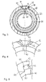
- Fig. 4 is a schematic partial section of the intermediate plate 20 with the hopper 42 in the non-pressed and in the pressed state against the bearing housing 12 is shown.
- the dashed funnel 42 shows the hopper 42 in the non-pressed state. Since the funnel wall 48 is elastic, it springs in the pressed state, as in Fig. 4 shown with the solid lines. Due to the elastic material properties of the funnel wall 48, a counterforce is thus generated which presses against the bearing housing 12. This ensures a seal.
- the intermediate plate 20 in the region of the funnel 42 has a projection 54.
- the projection 54 engages in the recess 50 of the bearing housing 12 and thus forms an anti-rotation.
- a second embodiment of the funnel 42 is shown.
- the funnel 42 is approximately Y-shaped, wherein the funnel wall 48 has different wall thicknesses.
- Such a trained funnel 42 is advantageous if a higher contact pressure for pressing and sealing is necessary.
- FIG Fig. 7 A third embodiment of the funnel 42 is shown in FIG Fig. 7 shown.
- the funnel wall 48 has approximately a spring-like configuration.
- Fig. 8 shows a fourth embodiment of the funnel 42.
- a stiffening rib 56 for stiffening the funnel wall 48 is arranged on the funnel wall 48. It is also possible to attach a plurality of stiffening ribs 56, which are arranged circumferentially on the funnel wall 48. Further, it is possible to attach only a circumferential stiffening rib 56 to the funnel wall 48.
- the first three embodiments of the funnel 42 can also be provided with one or more or a circumferential stiffening rib 56.
- the filling of the bearing 10 via the filling channel 40 will be described below.
- a filling nozzle of a filling device not shown is introduced through the opening 13 of the bearing housing 12 in the filling channel 40.
- the filling of the working chamber 26 and the compensation chamber 28 takes place with hydraulic fluid.
- the hydraulic fluid flows from the filling channel 40 into the overflow channel 30 and finally via the overflow channel openings 32 in the working chamber 26 and compensation chamber 28.
- a closure body 58 as shown in the Fig. 1 and 3 is shown.
- the closure body 58 is pressed from the outside into the filling channel 40, so that the filling channel 40 is sealed.
- the closure body 48 is formed in the present embodiment as a steel or elastomeric ball.
- drops may accumulate in the radially outer region of the filling channel 40, which are not captured by the closure body 58. However, these drops are collected during operation from the hopper 42, which serves as a reservoir for these drops, so that they can not escape via the opening 13 from the bearing 10 and the surrounding parts are wetted.
- the bearing 10 according to the invention is characterized in that on the outer circumference of the intermediate plate 20, a funnel 42 is arranged, which surrounds the filling channel 40 and sealingly abuts against the bearing housing 12 in the region of the opening 13.
- the funnel 42 serves as a reservoir for liquid, which is located in the radially outer region of the filling channel 40. This prevents leakage of the liquid during operation and, as a result, wetting of the surrounding parts.
- the bearing 10 is characterized by its cost-effective production, as consuming measures to remove the filling medium avoided and thus shorter cycle times are possible.
Landscapes
- Engineering & Computer Science (AREA)
- General Engineering & Computer Science (AREA)
- Mechanical Engineering (AREA)
- Combined Devices Of Dampers And Springs (AREA)
Description
- Die vorliegende Erfindung betrifft ein hydraulisch dämpfendes Lager, insbesondere zur Lagerung eines Kraftfahrzeugmotors, mit einem Lagergehäuse, einer Tragfeder aus einem elastomeren Material zur Abstützung eines Lagerkerns, einer Arbeitskammer, die von der Tragfeder begrenzt ist, einer Ausgleichskammer, die durch eine Zwischenplatte von der Arbeitskammer getrennt ist und durch eine Ausgleichsmembran aus elastomeren Material begrenzt ist, wobei die Arbeitskammer und die Ausgleichskammer über einen in die Zwischenplatte eingebrachten Überströmkanal miteinander verbunden und mit hydraulischer Flüssigkeit gefüllt sind, wobei in der Zwischenplatte ein radial nach außen führender Befüllungskanal eingebracht ist, der mit dem Überströmkanal verbunden ist und wobei das Lagergehäuse im Bereich des Befüllungskanals eine Öffnung aufweist.
- Derartige Lager werden insbesondere zur Abstützung eines Kraftfahrzeugmotors verwendet, um einerseits die von Fahrbahnunebenheiten hervorgerufenen Schwingungen zu dämpfen und andererseits akustische Schwingungen zu isolieren. Die von den Fahrbahnunebenheiten hervorgerufenen Schwingungen werden durch ein hydraulisches System gedämpft, wobei das hydraulische System durch die flüssigkeitsgefüllte Arbeitskammer, die Ausgleichskammer und den die beiden Kammern miteinander verbindenden Überströmkanal gebildet wird. Die Funktionsweise des hydraulischen Systems kann wie folgt beschrieben werden. Die Arbeitskammer wird durch eine Bewegung der Tragfeder vergrößert oder verkleinert, wobei die in der Arbeitskammer befindliche Flüssigkeit über den Überströmkanal in die Ausgleichskammer gedrückt wird. Die im Überströmkanal schwingende Flüssigkeitssäule bewirkt eine Dämpfung.
- Die Befüllung der Kammern mit einem Füllmedium erfolgt üblicherweise entweder über den Kern oder über einen in der Zwischenplatte eingebrachten Befüllungskanal. Zur Befüllung des Lagers über den Befüllungskanal wird das Lager mittels einer Befüllvorrichtung evakuiert und anschließend befüllt, wobei das Füllmedium über den Befüllungskanal in den Überströmkanal und von dort aus in die beiden Kammern fließt. Zur Abdichtung wird in den Befüllungskanal ein Verschlusskörper, wie beispielsweise eine Stahl- oder Elastomerkugel, eingepresst. Nachteilig bei der Befüllung über den Befüllungskanal ist, dass sich beim Entfernen der Befüllvorrichtung Tropfen im radial äußeren Bereich des Befüllungskanals, der von dem Verschlusskörper nicht mehr erfasst wird, ansammeln können. Diese Flüssigkeit kann im Betrieb aus dem Befüllungskanal austreten und die umgebenden Teile benetzen und durch Kapillarwirkung zwischen die umgebenden Teile gelangen. Während der Nutzungsdauer des Lagers kann diese Flüssigkeit dann austreten und führt häufig zu Reklamationen seitens der Kunden, obwohl keine Funktionsbeeinträchtigung vorliegt.
- Aus der
DE 37 01 264 A1 geht ein Hydrolager der eingangs genannten Art hervor, bei dem zur Befüllung der beiden Kammern in der Düsenplatte ein Befüllungskanal eingebracht ist. Der Befüllungskanal wird mittels eines Verschlusskörpers, der von außen eingesetzt wird, verschlossen. - In der
DE 60 2005 001 880 T2 ist ein Hydrolager offenbart, das eine elastomere Tragfeder aufweist, die eine Arbeitskammer begrenzt und sich an einer Zwischenplatte abstützt. Die Zwischenplatte ist mit Durchgängen versehen, die in eine Ausgleichskammer führen. Die Ausgleichskammer ist von einer in einer topfförmigen Bodenabdeckung aufgenommenen Ausgleichsmembran begrenzt. Beide Kammern sind mit einem viskosen Fluid befüllt. Zur Befüllung der Kammern ist an der Zwischenplatte ein Ventil radial angeordnet, das mit einem der Kanäle verbunden ist. Das Ventil sorgt für einen sicheren Verschluss des Durchgangs. Nachteilig hierbei ist, dass ein Ventil zum Verschließen des Befüllungskanals im Vergleich zu einem Verschlusskörper teuer ist, so dass ein derartiges Lager in der Herstellung teuer ist. - Aus der
JP 2009-275748 A - Der Erfindung liegt daher die Aufgabe zugrunde, ein Lager der eingangs genannten Art derart weiterzubilden, dass ein Benetzen der umliegenden Teile vermieden wird und das gleichzeitig kostengünstig in der Herstellung ist.
- Zur Lösung der Aufgabe wird bei einem Lager der eingangs genannten Art vorgeschlagen, dass am Außenumfang der Zwischenplatte ein Trichter mit einem Trichtereinlass und einem Trichterauslass vorgesehen ist und dass der Trichtereinlass die Öffnung im Lagergehäuse umgibt und dichtend an dem Lagergehäuse anliegt. Ferner ist der Trichter federnd ausgebildet.
- Das erfindungsgemäße Lager zeichnet sich durch den am Außenumfang der Zwischenplatte angeordneten Trichter aus, der als Auffangvorrichtung für das im Befüllungskanal befindliche Füllmedium dient. Dies verhindert ein durch Kapillareffekt bedingtes Eindringen von Füllmedium zwischen die Bauteile. Demgemäß wird ein Benetzen der umgebenden Teile während des Betriebs verhindert, da der Trichter das überschüssige Füllmedium sammelt und bis zur Entfernung speichert. Ferner zeichnet sich das erfindungsgemäße Lager durch seine kostengünstige Herstellung aus, da aufwändige Maßnahmen und Verfahren zur Beseitigung des in dem Befüllungskanal befindlichen Füllmediums entfallen und somit kürzere Taktzeiten zur Fertigung des Lagers ermöglicht werden.
- Der Trichter ist federnd ausgebildet. Infolge der Verformung kann sich der Trichter an das Lagergehäuse anschmiegen. Zudem wird bei einer Deformation des Trichters eine Rückstellkraft erzeugt, sodass der Trichter mit einer ausreichenden Anpresskraft gegen das Lagergehäuse drückt und dichtend an dem Lagergehäuse anliegt. Ferner ermöglicht die federnde Ausbildung des Trichters, dass mögliche toleranzbedingte Abweichungen, Gussformschrägen oder sonstige Abweichungen ausgeglichen werden können.
- In einer vorteilhaften Ausgestaltung ist der Trichter stoffschlüssig mit der Zwischenplatte verbunden. Hierdurch wird die Handhabung bei der Montage des erfindungsgemäßen Hydrolagers verbessert, da ein vorheriges Positionieren des Trichters und anschließendes Einsetzen der Zwischenplatte entfällt. Ausserdem ist diese Ausgestaltung kostengünstiger, da keine zusätzliche Form anfällt und der Lagermontageprozess nicht verlängert wird.
- Ein Rand des Trichtereinlasses ist vorteilhaft rund oder spitz ausgebildet. Ein rund oder spitz ausgebildeter Rand ermöglicht eine verbesserte Abdichtung. In einer weiteren vorteilhaften Ausgestaltung weist eine Trichterwand des Trichters unterschiedliche Wandstärken auf. Je nach erforderlicher Anpresskraft oder Abdichtwirkung wird die Trichterwand mit einer unterschiedlichen Wandstärke ausgebildet. Beispielsweise werden für größere Anpresskräfte dickere Wandstärken benötigt.
- Vorteilhafterweise ist an einer dem Trichter gegenüberliegenden Außenseite der Zwischenplatte wenigstens ein Toleranzausgleichselement angeordnet. Das Toleranzausgleichselement sorgt für einen Ausgleich, falls die Zwischenplatte und/oder das Lagergehäuse unter Normmaß gefertigt worden ist. In einem derartigen Fall drückt das Toleranzausgleichselement die Zwischenplatte in Richtung der Öffnung des Lagergehäuses, sodass der Trichter trotz Maßabweichung der Zwischenplatte und/oder des Lagergehäuses weiterhin dichtend an dem Lagergehäuse anliegt. Das Toleranzausgleichselement ist nachgiebig ausgebildet, sodass dieses für den Fall, dass die Zwischenplatte und das Lagergehäuse Normmaß aufweisen, zusammengedrückt werden kann. Ferner können auch eine Vielzahl an Toleranzausgleichselementen nebeneinander und/oder übereinander an der Zwischenplatte angeordnet sein.
- Bei einer vorteilhaften Ausgestaltung ist das Toleranzausgleichselement in Form einer Erhebung ausgebildet. Das Toleranzausgleichselement kann hierbei vorteilhafterweise dreieckig oder rechteckig ausgebildet sein, wobei auch jegliche andere Form der Erhebung denkbar wäre.
- In einer weiteren vorteilhaften Ausgestaltung ist das Toleranzausgleichselement als Verdrehsicherung für die Zwischenplatte ausgebildet. Somit kann bei entsprechender Gestaltung das Toleranzausgleichselement in einer zweiten Funktion eine Verdrehsicherheit gewährleisten.
- Vorteilhafterweise weist das Lagergehäuse im Bereich der Öffnung einen Rücksprung auf, in dem der Trichter einliegt. Hierdurch wird eine sichere Aufnahme des Trichters in dem Lagergehäuse gewährleistet.
- Bei einer weiteren vorteilhaften Ausgestaltung weist die Zwischenplatte im Bereich des Trichters einen Vorsprung auf, wobei der Vorsprung in den Rücksprung des Lagergehäuses eingreift. Hierdurch wird eine Verdrehsicherung geschaffen, sodass die Handhabbarkeit bei der Montage des Lagers verbessert wird.
- Vorteilhafterweise ist in dem Befüllungskanal ein Verschlusskörper zum Verschließen des Befüllungskanals einbringbar. Der Verschlusskörper wird in den Befüllungskanal von außen eingepresst. Hierdurch wird ein Austreten des in den Kammern befindlichen Füllmediums vermieden. Der in den Befüllungskanal einzupressende Verschlusskörper kann aus Stahl oder einem Elastomer bestehen und die Form einer Kugel, eines Quaders oder eines anderen Körpers mit rundem, quadratischem oder rechteckigem Querschnitt haben. Auch ein Verschluss durch einen Niet ist denkbar.
- Vorteilhafterweise wird der Befüllungskanal durch einen sich verfestigenden Stoff verschlossen. Hierbei handelt es sich um Stoffe, die sich nach Einbringen in den Befüllungskanal verfestigen, wie beispielsweise Silikon oder PU-Schaum (Montageschaum).
- In einer vorteilhaften Ausgestaltung ist die Zwischenplatte aus einem faserverstärkten Kunststoff hergestellt. Der faserverstärkte Kunststoff sorgt für eine ausreichende Festigkeit und zugleich für eine Gewichtsreduzierung der Zwischenplatte. Als faserverstärkter Kunststoff kann glasfaserverstärktes Polyamid, PEEK und PPS verwendet werden. Als Fasermaterial kann außer Glas auch Kupfer oder Aramid verwendet werden. Der Glasfaseranteil beträgt vorteilhafterweise zwischen 0 und 50% an dem faserverstärktem Kunststoff. Die Fasern können in Form von Fäden oder Kugeln in dem faserverstärkten Kunststoff vorliegen.
- Vorteilhafterweise ist der Trichter aus einem Elastomer hergestellt. Hierdurch gewährleistet der Trichter eine verbesserte Abdichtfunktion. Ferner ermöglicht die Herstellung des Trichters aus einem Elastomer, dass dieser elastische bzw. federnde Eigenschaften aufweist, wie dies zum Anpressen und damit zum Abdichten erforderlich ist. Als Elastomere können Naturkautschuk oder synthetische Elastomere, wie beispielsweise EPDM oder Silikon oder auch TPE verwendet werden.
- In einer vorteilhaften Ausgestaltung sind der Trichter und die Zwischenplatte aus dem gleichen Material hergestellt. Hierbei kann der Trichter aus dem gleichen faserverstärkten Kunststoff wie die Zwischenplatte hergestellt sein. Die federnden Eigenschaften werden dann durch Materialeigenschaften und/oder geeignete Formgebung erzeugt.
- Nachfolgend wird die Erfindung anhand von Ausführungsbeispielen näher beschrieben, die in den Zeichnungen schematisch dargestellt sind. Hierbei zeigen:
- Fig. 1
- einen Vertikalschnitt durch das erfindungsgemäße Lager;
- Fig. 2
- eine perspektivische Ansicht der Zwischenplatte gemäß einer ersten Ausführungsform mit einer ersten Ausführungsform eines Trichters;
- Fig. 3
- einen Horizontalschnitt durch das erfindungsgemäße Lager entlang der Linie III-III in
Fig. 1 ; - Fig. 4
- einen schematischen Teilausschnitt des Trichters gemäß der ersten Ausführungsform im eingebauten bzw. nicht eingebauten Zustand;
- Fig. 5
- einen schematischen Teilausschnitt der Zwischenplatte gemäß einer zweiten Ausführungsform im Bereich des Trichters;
- Fig. 6
- einen schematischen Teilausschnitt eines Trichters gemäß einer zweiten Ausführungsform;
- Fig. 7
- einen schematischen Teilausschnitt eines Trichters gemäß einer dritten Ausführungsform und
- Fig. 8
- einen schematischen Teilausschnitt eines Trichters gemäß einer vierten Ausführungsform.
- In
Fig. 1 ist ein hydraulisch dämpfendes Lager 10 zur Lagerung eines nicht näher dargestellten Kraftfahrzeugmotors gezeigt. - Das Lager 10 weist ein zylinderförmiges Lagergehäuse 12 mit einer Öffnung 13, eine Tragfeder 14 aus einem elastomeren Material zur Abstützung eines Lagerkerns 16, einen Lagergehäusedeckei 18, eine Zwischenplatte 20 und eine Ausgleichsmembran 22 auf. In die Tragfeder 14 ist eine Armierung 24 zur Verstärkung eingebracht. Die Tragfeder 14 und die Zwischenplatte 20 begrenzen eine Arbeitskammer 26. Ferner begrenzen die Zwischenplatte 20 und die Ausgleichsmembran 22 eine Ausgleichskammer 28. Die Arbeitskammer 26 und die Ausgleichkammer 28 sind durch einen in die Zwischenplatte 20 eingebrachten Überströmkanal 30 miteinander verbunden. Sowohl die Arbeitskammer 26 als auch die Ausgleichskammer 28 sind mit einer hydraulischen Flüssigkeit gefüllt.
-
Fig. 2 zeigt eine perspektivische Ansicht der Zwischenplatte 20. An einer Oberseite der Zwischenplatte 20 ist eine Überströmkanalöffnung 32 eingebracht, die einen Einlass und/oder Auslass der hydraulischen Flüssigkeit in den Überströmkanal 30 und damit in die Ausgleichskammer 28 darstellt. An einer der Arbeitskammer 28 zugewandten Unterseite der Zwischenplatte 20 ist eine nicht dargestellte zweite Überströmkanalöffnung eingebracht, sodass die beiden Kammern 26, 28 miteinander verbunden sind. Ferner ist an der Oberseite ein oberes Gitter 34 eingebracht. Wie ausFig. 1 ersichtlich ist, weist die Zwischenplatte 20 an einer der Arbeitskammer 28 zugewandten Unterseite ein unteres Gitter 36 auf. Zwischen den beiden Gittern 34, 36 ist eine elastische Entkopplungsmembran 38 eingebracht. Des Weiteren weist die Zwischenplatte 20 einen von dem Überströmkanal 30 radial nach außen führenden Befüllungskanal 40 auf. Der Befüllungskanal 40 ist von einem Trichter 42 umgeben. Der Trichter 42 ist stoffschlüssig mit der Zwischenplatte 20 verbunden. - Wie in
Fig. 3 dargestellt ist, weist der Trichter 42 einen Trichtereinlass 44, einen Trichterauslass 46 und eine Trichterwand 48 auf. Hierbei umgibt der Trichterauslass 46 den Befüllungskanal 40, wobei der Trichter 42 stoffschlüssig über seinen Trichterauslass 46 mit der Zwischenplatte 20 verbunden ist. Die Trichterwand 48 ist elastisch und federnd ausgebildet. Ein den Trichtereinlass 44 umlaufender Rand 49 der Trichterwand 48 ist rund ausgebildet. Ferner kann der umlaufende Rand 49 auch spitz gestaltet sein. Der Trichter 42 ist aus einem weichen elastischen Material, wie beispielsweise Gummi oder Elastomer, hergestellt. - Der Trichter 42 liegt in einem in dem Lagergehäuse 12 ausgebildeten Rücksprung 50 im Bereich der Öffnung 13 des Lagergehäuses 12 ein. Hierbei drückt der umlaufende Rand 49 abdichtend gegen das Lagergehäuse 12, wobei der Trichtereinlass 44 die Öffnung 13 des Lagergehäuses 12 umgibt.
- Zum Ausgleich etwaiger Maßabweichungen der Zwischenplatte 20 und/oder des Lagergehäuses 12 weist die Zwischenplatte 20 an ihrem Außenumfang auf einer dem Trichter 42 gegenüber liegenden Seite Toleranzausgleichselemente 52 auf. Die Toleranzausgleichselemente 52 sind als dreiecksförmige elastische Erhebungen ausgebildet und sorgen dafür, dass bei Maßabweichungen der Trichter 42, in Richtung des Lagergehäuses 12 gedrückt wird Somit wird selbst bei Maßabweichungen der Zwischenplatte 20 bzw. des Lagergehäuses 12 eine ausreichende Anpresskraft des Trichters 42 gegen das Lagergehäuse 12 und damit einhergehend eine Abdichtung sichergestellt.
- In der
Fig. 4 ist ein schematischer Teilausschnitt der Zwischenplatte 20 mit dem Trichter 42 im nicht-angedrückten und im angedrückten Zustand gegen das Lagergehäuse 12 dargestellt. Der strichlinierte Trichter 42 zeigt den Trichter 42 im nicht-angedrückten Zustand. Da die Trichterwand 48 elastisch ausgebildet ist, federt diese im angedrückten Zustand ein, wie dies inFig. 4 mit den durchgehenden Strichen gezeigt ist. Aufgrund der elastischen Materialeigenschaften der Trichterwand 48 wird somit eine Gegenkraft erzeugt, die gegen das Lagergehäuse 12 drückt. Hierdurch wird eine Abdichtung gewährleistet. - Bei einer in
Fig. 5 dargestellten zweiten Ausführungsform der Zwischenplatte 20, weist die Zwischenplatte 20 im Bereich des Trichters 42 einen Vorsprung 54 auf. Der Vorsprung 54 greift in den Rücksprung 50 des Lagergehäuses 12 ein und bildet so eine Verdrehsicherung. - In
Fig. 6 ist eine zweite Ausführungsform für den Trichter 42 dargestellt. Hierbei ist der Trichter 42 näherungsweise Y-förmig ausgebildet, wobei die Trichterwand 48 unterschiedliche Wandstärken aufweist. Ein derart ausgebildeter Trichter 42 ist dann von Vorteil, wenn eine höhere Anpresskraft zum Anpressen und Abdichten notwendig ist. - Eine dritte Ausführungsform des Trichters 42 ist in
Fig. 7 dargestellt. Hierbei weist die Trichterwand 48 näherungsweise eine federförmige Ausgestaltung auf. -
Fig. 8 zeigt eine vierte Ausführungsform des Trichters 42. Gemäß der vierten Ausführungsform des Trichters 42 ist an der Trichterwand 48 eine Versteifungsrippe 56 zur Versteifung der Trichterwand 48 angeordnet. Es ist auch möglich, eine Vielzahl an Versteifungsrippen 56, die umlaufend an der Trichterwand 48 angeordnet sind, anzubringen. Ferner ist es möglich, lediglich eine umlaufende Versteifungsrippe 56 an den Trichterwand 48 anzubringen. Des Weiteren lassen sich die ersten drei Ausführungsformen des Trichters 42 auch mit einer oder mehreren oder einer umlaufenden Versteifungsrippe 56 versehen. - Im Nachfolgenden wird die Befüllung des Lagers 10 über den Befüllungskanal 40 beschrieben. Zur Befüllung wird ein Befüllstutzen einer nicht näher dargestellten Befüllvorrichtung durch die Öffnung 13 des Lagergehäuses 12 in den Befüllungskanal 40 eingebracht. Anschließend erfolgt die Befüllung der Arbeitskammer 26 und der Ausgleichskammer 28 mit hydraulischer Flüssigkeit. Hierbei strömt die hydraulische Flüssigkeit von dem Befüllungskanal 40 in den Überströmkanal 30 und schließlich über die Überströmkanalöffnungen 32 in die Arbeitskammer 26 und Ausgleichkammer 28. Nach dem Befüllen wird der Befüllstutzen entfernt und der Befüllungskanal 40 wird mit einem Verschlusskörper 58 verschlossen, wie dies in den
Fig. 1 und3 dargestellt ist. Hierzu wird der Verschlusskörper 58 von außen in den Befüllungskanal 40 eingepresst, sodass der Befüllungskanal 40 dicht verschlossen ist. Der Verschlusskörper 48 ist im vorliegenden Ausführungsbeispiel als Stahl- oder Elastomerkugel ausgebildet. - Beim Herausziehen des Befüllstutzens können sich Tropfen im radial äußeren Bereich des Befüllungskanals 40 ansammeln, die nicht von dem Verschlusskörper 58 erfasst werden. Diese Tropfen werden jedoch während des Betriebs von dem Trichter 42, der als Reservoir für diese Tropfen dient, aufgefangen, sodass diese nicht über die Öffnung 13 aus dem Lager 10 austreten können und die umliegenden Teile benetzt werden.
- Das erfindungsgemäße Lager 10 zeichnet sich dadurch aus, dass am Außenumfang der Zwischenplatte 20 ein Trichter 42 angeordnet ist, der den Befüllungskanal 40 umgibt und dichtend an dem Lagergehäuse 12 im Bereich der Öffnung 13 anliegt. Der Trichter 42 dient als Reservoir für Flüssigkeit, die sich im radial außen liegenden Bereich des Befüllungskanals 40 befindet. Damit wird ein Austreten der Flüssigkeit während des Betriebs und damit einhergehend ein Benetzen der umgebenden Teile verhindert. Das Lager 10 zeichnet sich durch seine kostengünstige Herstellung aus, da aufwändige Maßnahmen zur Entfernung des Füllmediums vermieden und somit kürzere Taktzeiten ermöglicht werden.
-
- 10
- Hydrolager
- 12
- Lagergehäuse
- 13
- Öffnung
- 14
- Tragfeder
- 16
- Lagerkern
- 18
- Lagergehäusedeckel
- 20
- Zwischenplatte
- 22
- Ausgleichsmembran
- 24
- Armierung
- 26
- Arbeitskammer
- 28
- Ausgleichskammer
- 30
- Überströmkanal
- 32
- Überströmkanalöffnung
- 34
- oberes Gitter
- 36
- unteres Gitter
- 38
- Entkopplungsmembran
- 40
- Befüllungskanal
- 42
- Trichter
- 44
- Trichtereinlass
- 46
- Trichterauslass
- 48
- Trichterwand
- 49
- umlaufende Rand
- 50
- Rücksprung
- 52
- Toleranzausgleichselemente
- 54
- Vorsprung
- 56
- Versteifungsrippe
- 58
- Verschlusskörper
Claims (14)
- Hydraulisch dämpfendes Lager (10), insbesondere zur Lagerung eines Kraftfahrzeugmotors, mit einem Lagergehäuse (12), einer Tragfeder (14) aus einem elastomeren Material zur Abstützung eines Lagerkerns (16), einer Arbeitskammer (26), die von der Tragfeder (14) begrenzt ist, einer Ausgleichskammer (28), die durch eine Zwischenplatte (20) von der Arbeitskammer (26) getrennt ist und durch eine Ausgleichsmembran (22) aus elastomeren Material begrenzt ist, wobei die Arbeitskammer (26) und die Ausgleichskammer (28) über einen in die Zwischenplatte (20) eingebrachten Überströmkanal (30) miteinander verbunden und mit hydraulischer Flüssigkeit gefüllt sind, wobei in der Zwischenplatte (20) ein radial nach außen führender Befüllungskanal (40) eingebracht ist, der mit dem Überströmkanal (30) verbunden ist, und wobei das Lagergehäuse (12) im Bereich des Befüllungskanals (40) eine Öffnung (13) aufweistwobei am Außenumfang der Zwischenplatte (20) ein Trichter (42) mit einem Trichtereinlass (44) und einem Trichterauslass (46) vorgesehen ist und dass der Trichtereinlass (44) die Öffnung (13) im Lagergehäuse (12) umgibt und dichtend an dem Lagergehäuse (12) anliegt, dadurch gekennzeichnet, dass der Trichter (42) federnd ausgebildet ist.
- Lager nach Anspruch 1, dadurch gekennzeichnet, dass der Trichter (42) stoffschlüssig mit der Zwischenplatte (20) verbunden ist.
- Lager nach einem der vorhergehenden Ansprüche, dadurch gekennzeichnet, dass ein Rand (49) des Trichtereinlasses (44) rund oder spitz ausgebildet ist.
- Lager nach einem der vorhergehenden Ansprüche, dadurch gekennzeichnet, dass eine Trichterwand (48) des Trichters (42) unterschiedliche Wandstärken aufweist.
- Lager nach einem der vorhergehenden Ansprüche, dadurch gekennzeichnet, dass an einer dem Trichter (42) gegenüberliegenden Außenseite der Zwischenplatte (20) wenigstens ein Toleranzausgleichselement (52) angeordnet ist.
- Lager nach Anspruch 5, dadurch gekennzeichnet, dass das Toleranzausgleichselemente (52) in Form einer Erhebung ausgebildet ist.
- Lager nach Anspruch 5 oder 6, dadurch gekennzeichnet, dass das Toleranzausgleichselement (52) als Verdrehsicherung für die Zwischenplatte (20) ausgebildet ist.
- Lager nach einem der vorhergehenden Ansprüche, dadurch gekennzeichnet, dass das Lagergehäuse (12) im Bereich der Öffnung (13) einen Rücksprung (50) aufweist, in dem der Trichter (42) eingreift.
- Lager nach Anspruch 7, dadurch gekennzeichnet, dass die Zwischenplatte (20) im Bereich des Trichters (42) einen Vorsprung (54) aufweist, wobei der Vorsprung (54) in den Rücksprung (50) des Lagergehäuses (12) eingreift.
- Lager nach einem der vorhergehenden Ansprüche, dadurch gekennzeichnet, dass in dem Befüllungskanal (40) ein Verschlusskörper (58) zum Verschließen des Befüllungskanals (40) einbringbar ist.
- Lager nach einem der Ansprüche 1 bis 9, dadurch gekennzeichnet, dass der Befüllungskanal (40) durch einen sich verfestigenden Stoff verschlossen wird.
- Lager nach einem der vorhergehenden Ansprüche, dadurch gekennzeichnet, dass die Zwischenplatte (20) aus einem faserverstärktem Kunststoff hergestellt ist.
- Lager nach einem der vorhergehenden Ansprüche, dadurch gekennzeichnet, dass der Trichter (42) aus einem Elastomer hergestellt ist.
- Lager nach einem der vorhergehenden Ansprüche, dadurch gekennzeichnet, dass der Trichter (42) und die Zwischenplatte (20) aus dem gleichen Material hergestellt sind.
Applications Claiming Priority (2)
| Application Number | Priority Date | Filing Date | Title |
|---|---|---|---|
| DE201110006156 DE102011006156B4 (de) | 2011-03-25 | 2011-03-25 | Hydraulisch dämpfendes Lager |
| PCT/EP2012/055253 WO2012130772A1 (de) | 2011-03-25 | 2012-03-23 | Hydraulisch dämpfendes lager |
Publications (2)
| Publication Number | Publication Date |
|---|---|
| EP2689160A1 EP2689160A1 (de) | 2014-01-29 |
| EP2689160B1 true EP2689160B1 (de) | 2016-01-06 |
Family
ID=45937256
Family Applications (1)
| Application Number | Title | Priority Date | Filing Date |
|---|---|---|---|
| EP12713008.6A Active EP2689160B1 (de) | 2011-03-25 | 2012-03-23 | Hydraulisch dämpfendes lager |
Country Status (3)
| Country | Link |
|---|---|
| EP (1) | EP2689160B1 (de) |
| DE (1) | DE102011006156B4 (de) |
| WO (1) | WO2012130772A1 (de) |
Families Citing this family (2)
| Publication number | Priority date | Publication date | Assignee | Title |
|---|---|---|---|---|
| JP5941966B2 (ja) * | 2014-12-08 | 2016-06-29 | 住友理工株式会社 | 流体封入式防振装置 |
| CN111981078B (zh) * | 2020-08-04 | 2025-03-25 | 亚新科噪声与振动技术(安徽)有限公司 | 一种汽车液压悬置的隔振结构 |
Family Cites Families (5)
| Publication number | Priority date | Publication date | Assignee | Title |
|---|---|---|---|---|
| DE3701264A1 (de) | 1987-01-17 | 1988-07-28 | Opel Adam Ag | Hydrolager |
| JPH09280301A (ja) * | 1996-04-18 | 1997-10-28 | Bridgestone Corp | 防振装置 |
| FR2868821B1 (fr) | 2004-04-08 | 2008-02-15 | Hutchinson Sa | Dispositif antivibratoire |
| JP2009275748A (ja) | 2008-05-13 | 2009-11-26 | Bridgestone Corp | 防振装置、及び防振装置の製造方法 |
| CN102165215B (zh) * | 2008-10-28 | 2013-11-06 | 株式会社普利司通 | 隔振装置的制造方法 |
-
2011
- 2011-03-25 DE DE201110006156 patent/DE102011006156B4/de not_active Expired - Fee Related
-
2012
- 2012-03-23 EP EP12713008.6A patent/EP2689160B1/de active Active
- 2012-03-23 WO PCT/EP2012/055253 patent/WO2012130772A1/de not_active Ceased
Also Published As
| Publication number | Publication date |
|---|---|
| WO2012130772A1 (de) | 2012-10-04 |
| DE102011006156A1 (de) | 2012-09-27 |
| DE102011006156B4 (de) | 2013-02-21 |
| EP2689160A1 (de) | 2014-01-29 |
Similar Documents
| Publication | Publication Date | Title |
|---|---|---|
| EP2460984B1 (de) | Ölabscheidereinheit | |
| DE102015118931B4 (de) | Hydrolager | |
| DE19818334A1 (de) | Sicherheitsventil für eine Filtervorrichtung und ein Verfahren zur Befestigung desselben | |
| DE102007012158A1 (de) | Pneumatisch dämpfendes Lager | |
| EP2280198B1 (de) | Verschlusseinheit für ein Kolben-Zylinderaggregat | |
| EP2855943B1 (de) | Geberzylinder | |
| DE102013200511A1 (de) | Filtereinrichtung | |
| DE102011006156B4 (de) | Hydraulisch dämpfendes Lager | |
| DE102014220675B4 (de) | Armatur mit Wechselsitzsystem | |
| DE102017129586A1 (de) | Druckausgleichseinrichtung für ein Getriebegehäuse | |
| DE102018220628B4 (de) | Schwingungsdämpfer und Fahrzeug | |
| DE102010030665A1 (de) | Stützring, insbesondere für eine Fluidbaugruppe in einem Fahrzeug | |
| DE102015109691A1 (de) | Entlüftungsventil zur Verwendung in einem Kühlsystem eines Kraftfahrzeugs | |
| DE202008009501U1 (de) | Filtereinrichtung, insbesondere zur Filtration von Gasen oder Flüssigkeiten in Fahrzeugen | |
| DE102011106460A1 (de) | Nehmerzylinder | |
| DE102005048593B4 (de) | Kunststoffleitung, insbesondere hydraulische Kupplungsdruck-Übertragungsleitung für ein Kraftfahrzeug | |
| DE102013215243A1 (de) | Filtereinrichtung | |
| DE102011013999A1 (de) | Schwingungsdämpfer | |
| DE102013206290A1 (de) | Motorlager | |
| DE102010026946A1 (de) | Verbundkolben | |
| DE102015119332B4 (de) | Deckel | |
| DE102019120221A1 (de) | Ventil zur Regelung von Drücken eines Strömungsmittels | |
| DE102019133667A1 (de) | Vorrichtung zur Regelung von Drücken eines Strömungsmittels mit einem Ven-til | |
| DE102013201292B4 (de) | Kraftfahrzeuggetriebe mit einer Abdicht- und Abflussvorrichtung | |
| DE102014226091A1 (de) | Hydrolager, Kraftfahrzeug mit einem derartigen Hydrolager sowie Verfahren zur Herstellung von einer integralen Einheit für ein derartiges Hydrolager |
Legal Events
| Date | Code | Title | Description |
|---|---|---|---|
| PUAI | Public reference made under article 153(3) epc to a published international application that has entered the european phase |
Free format text: ORIGINAL CODE: 0009012 |
|
| 17P | Request for examination filed |
Effective date: 20131017 |
|
| AK | Designated contracting states |
Kind code of ref document: A1 Designated state(s): AL AT BE BG CH CY CZ DE DK EE ES FI FR GB GR HR HU IE IS IT LI LT LU LV MC MK MT NL NO PL PT RO RS SE SI SK SM TR |
|
| DAX | Request for extension of the european patent (deleted) | ||
| 17Q | First examination report despatched |
Effective date: 20150213 |
|
| GRAP | Despatch of communication of intention to grant a patent |
Free format text: ORIGINAL CODE: EPIDOSNIGR1 |
|
| INTG | Intention to grant announced |
Effective date: 20150930 |
|
| GRAS | Grant fee paid |
Free format text: ORIGINAL CODE: EPIDOSNIGR3 |
|
| RAP1 | Party data changed (applicant data changed or rights of an application transferred) |
Owner name: TRELLEBORGVIBRACOUSTIC GMBH |
|
| GRAA | (expected) grant |
Free format text: ORIGINAL CODE: 0009210 |
|
| AK | Designated contracting states |
Kind code of ref document: B1 Designated state(s): AL AT BE BG CH CY CZ DE DK EE ES FI FR GB GR HR HU IE IS IT LI LT LU LV MC MK MT NL NO PL PT RO RS SE SI SK SM TR |
|
| REG | Reference to a national code |
Ref country code: GB Ref legal event code: FG4D Free format text: NOT ENGLISH |
|
| REG | Reference to a national code |
Ref country code: CH Ref legal event code: EP |
|
| REG | Reference to a national code |
Ref country code: IE Ref legal event code: FG4D Free format text: LANGUAGE OF EP DOCUMENT: GERMAN |
|
| REG | Reference to a national code |
Ref country code: AT Ref legal event code: REF Ref document number: 769121 Country of ref document: AT Kind code of ref document: T Effective date: 20160215 |
|
| REG | Reference to a national code |
Ref country code: DE Ref legal event code: R096 Ref document number: 502012005657 Country of ref document: DE |
|
| REG | Reference to a national code |
Ref country code: FR Ref legal event code: PLFP Year of fee payment: 5 |
|
| REG | Reference to a national code |
Ref country code: LT Ref legal event code: MG4D |
|
| REG | Reference to a national code |
Ref country code: NL Ref legal event code: MP Effective date: 20160106 |
|
| PG25 | Lapsed in a contracting state [announced via postgrant information from national office to epo] |
Ref country code: NL Free format text: LAPSE BECAUSE OF FAILURE TO SUBMIT A TRANSLATION OF THE DESCRIPTION OR TO PAY THE FEE WITHIN THE PRESCRIBED TIME-LIMIT Effective date: 20160106 |
|
| PG25 | Lapsed in a contracting state [announced via postgrant information from national office to epo] |
Ref country code: GR Free format text: LAPSE BECAUSE OF FAILURE TO SUBMIT A TRANSLATION OF THE DESCRIPTION OR TO PAY THE FEE WITHIN THE PRESCRIBED TIME-LIMIT Effective date: 20160407 Ref country code: HR Free format text: LAPSE BECAUSE OF FAILURE TO SUBMIT A TRANSLATION OF THE DESCRIPTION OR TO PAY THE FEE WITHIN THE PRESCRIBED TIME-LIMIT Effective date: 20160106 Ref country code: FI Free format text: LAPSE BECAUSE OF FAILURE TO SUBMIT A TRANSLATION OF THE DESCRIPTION OR TO PAY THE FEE WITHIN THE PRESCRIBED TIME-LIMIT Effective date: 20160106 Ref country code: NO Free format text: LAPSE BECAUSE OF FAILURE TO SUBMIT A TRANSLATION OF THE DESCRIPTION OR TO PAY THE FEE WITHIN THE PRESCRIBED TIME-LIMIT Effective date: 20160406 Ref country code: ES Free format text: LAPSE BECAUSE OF FAILURE TO SUBMIT A TRANSLATION OF THE DESCRIPTION OR TO PAY THE FEE WITHIN THE PRESCRIBED TIME-LIMIT Effective date: 20160106 Ref country code: IT Free format text: LAPSE BECAUSE OF FAILURE TO SUBMIT A TRANSLATION OF THE DESCRIPTION OR TO PAY THE FEE WITHIN THE PRESCRIBED TIME-LIMIT Effective date: 20160106 |
|
| PG25 | Lapsed in a contracting state [announced via postgrant information from national office to epo] |
Ref country code: PL Free format text: LAPSE BECAUSE OF FAILURE TO SUBMIT A TRANSLATION OF THE DESCRIPTION OR TO PAY THE FEE WITHIN THE PRESCRIBED TIME-LIMIT Effective date: 20160106 Ref country code: PT Free format text: LAPSE BECAUSE OF FAILURE TO SUBMIT A TRANSLATION OF THE DESCRIPTION OR TO PAY THE FEE WITHIN THE PRESCRIBED TIME-LIMIT Effective date: 20160506 Ref country code: LV Free format text: LAPSE BECAUSE OF FAILURE TO SUBMIT A TRANSLATION OF THE DESCRIPTION OR TO PAY THE FEE WITHIN THE PRESCRIBED TIME-LIMIT Effective date: 20160106 Ref country code: LT Free format text: LAPSE BECAUSE OF FAILURE TO SUBMIT A TRANSLATION OF THE DESCRIPTION OR TO PAY THE FEE WITHIN THE PRESCRIBED TIME-LIMIT Effective date: 20160106 Ref country code: BE Free format text: LAPSE BECAUSE OF NON-PAYMENT OF DUE FEES Effective date: 20160331 Ref country code: IS Free format text: LAPSE BECAUSE OF FAILURE TO SUBMIT A TRANSLATION OF THE DESCRIPTION OR TO PAY THE FEE WITHIN THE PRESCRIBED TIME-LIMIT Effective date: 20160506 Ref country code: SE Free format text: LAPSE BECAUSE OF FAILURE TO SUBMIT A TRANSLATION OF THE DESCRIPTION OR TO PAY THE FEE WITHIN THE PRESCRIBED TIME-LIMIT Effective date: 20160106 Ref country code: RS Free format text: LAPSE BECAUSE OF FAILURE TO SUBMIT A TRANSLATION OF THE DESCRIPTION OR TO PAY THE FEE WITHIN THE PRESCRIBED TIME-LIMIT Effective date: 20160106 |
|
| REG | Reference to a national code |
Ref country code: DE Ref legal event code: R097 Ref document number: 502012005657 Country of ref document: DE |
|
| PG25 | Lapsed in a contracting state [announced via postgrant information from national office to epo] |
Ref country code: DK Free format text: LAPSE BECAUSE OF FAILURE TO SUBMIT A TRANSLATION OF THE DESCRIPTION OR TO PAY THE FEE WITHIN THE PRESCRIBED TIME-LIMIT Effective date: 20160106 Ref country code: EE Free format text: LAPSE BECAUSE OF FAILURE TO SUBMIT A TRANSLATION OF THE DESCRIPTION OR TO PAY THE FEE WITHIN THE PRESCRIBED TIME-LIMIT Effective date: 20160106 Ref country code: LU Free format text: LAPSE BECAUSE OF FAILURE TO SUBMIT A TRANSLATION OF THE DESCRIPTION OR TO PAY THE FEE WITHIN THE PRESCRIBED TIME-LIMIT Effective date: 20160323 Ref country code: MC Free format text: LAPSE BECAUSE OF FAILURE TO SUBMIT A TRANSLATION OF THE DESCRIPTION OR TO PAY THE FEE WITHIN THE PRESCRIBED TIME-LIMIT Effective date: 20160106 |
|
| REG | Reference to a national code |
Ref country code: CH Ref legal event code: PL |
|
| PLBE | No opposition filed within time limit |
Free format text: ORIGINAL CODE: 0009261 |
|
| STAA | Information on the status of an ep patent application or granted ep patent |
Free format text: STATUS: NO OPPOSITION FILED WITHIN TIME LIMIT |
|
| PG25 | Lapsed in a contracting state [announced via postgrant information from national office to epo] |
Ref country code: RO Free format text: LAPSE BECAUSE OF FAILURE TO SUBMIT A TRANSLATION OF THE DESCRIPTION OR TO PAY THE FEE WITHIN THE PRESCRIBED TIME-LIMIT Effective date: 20160106 Ref country code: CZ Free format text: LAPSE BECAUSE OF FAILURE TO SUBMIT A TRANSLATION OF THE DESCRIPTION OR TO PAY THE FEE WITHIN THE PRESCRIBED TIME-LIMIT Effective date: 20160106 Ref country code: SM Free format text: LAPSE BECAUSE OF FAILURE TO SUBMIT A TRANSLATION OF THE DESCRIPTION OR TO PAY THE FEE WITHIN THE PRESCRIBED TIME-LIMIT Effective date: 20160106 Ref country code: SK Free format text: LAPSE BECAUSE OF FAILURE TO SUBMIT A TRANSLATION OF THE DESCRIPTION OR TO PAY THE FEE WITHIN THE PRESCRIBED TIME-LIMIT Effective date: 20160106 |
|
| 26N | No opposition filed |
Effective date: 20161007 |
|
| REG | Reference to a national code |
Ref country code: IE Ref legal event code: MM4A |
|
| PG25 | Lapsed in a contracting state [announced via postgrant information from national office to epo] |
Ref country code: CH Free format text: LAPSE BECAUSE OF NON-PAYMENT OF DUE FEES Effective date: 20160331 Ref country code: LI Free format text: LAPSE BECAUSE OF NON-PAYMENT OF DUE FEES Effective date: 20160331 Ref country code: IE Free format text: LAPSE BECAUSE OF NON-PAYMENT OF DUE FEES Effective date: 20160323 |
|
| PG25 | Lapsed in a contracting state [announced via postgrant information from national office to epo] |
Ref country code: BG Free format text: LAPSE BECAUSE OF FAILURE TO SUBMIT A TRANSLATION OF THE DESCRIPTION OR TO PAY THE FEE WITHIN THE PRESCRIBED TIME-LIMIT Effective date: 20160406 Ref country code: SI Free format text: LAPSE BECAUSE OF FAILURE TO SUBMIT A TRANSLATION OF THE DESCRIPTION OR TO PAY THE FEE WITHIN THE PRESCRIBED TIME-LIMIT Effective date: 20160106 |
|
| REG | Reference to a national code |
Ref country code: FR Ref legal event code: PLFP Year of fee payment: 6 |
|
| PG25 | Lapsed in a contracting state [announced via postgrant information from national office to epo] |
Ref country code: MT Free format text: LAPSE BECAUSE OF FAILURE TO SUBMIT A TRANSLATION OF THE DESCRIPTION OR TO PAY THE FEE WITHIN THE PRESCRIBED TIME-LIMIT Effective date: 20160106 |
|
| REG | Reference to a national code |
Ref country code: FR Ref legal event code: PLFP Year of fee payment: 7 |
|
| REG | Reference to a national code |
Ref country code: AT Ref legal event code: MM01 Ref document number: 769121 Country of ref document: AT Kind code of ref document: T Effective date: 20170323 |
|
| PG25 | Lapsed in a contracting state [announced via postgrant information from national office to epo] |
Ref country code: CY Free format text: LAPSE BECAUSE OF FAILURE TO SUBMIT A TRANSLATION OF THE DESCRIPTION OR TO PAY THE FEE WITHIN THE PRESCRIBED TIME-LIMIT Effective date: 20160106 Ref country code: HU Free format text: LAPSE BECAUSE OF FAILURE TO SUBMIT A TRANSLATION OF THE DESCRIPTION OR TO PAY THE FEE WITHIN THE PRESCRIBED TIME-LIMIT; INVALID AB INITIO Effective date: 20120323 |
|
| PG25 | Lapsed in a contracting state [announced via postgrant information from national office to epo] |
Ref country code: MK Free format text: LAPSE BECAUSE OF FAILURE TO SUBMIT A TRANSLATION OF THE DESCRIPTION OR TO PAY THE FEE WITHIN THE PRESCRIBED TIME-LIMIT Effective date: 20160106 Ref country code: TR Free format text: LAPSE BECAUSE OF FAILURE TO SUBMIT A TRANSLATION OF THE DESCRIPTION OR TO PAY THE FEE WITHIN THE PRESCRIBED TIME-LIMIT Effective date: 20160106 |
|
| PG25 | Lapsed in a contracting state [announced via postgrant information from national office to epo] |
Ref country code: AT Free format text: LAPSE BECAUSE OF NON-PAYMENT OF DUE FEES Effective date: 20170323 |
|
| PG25 | Lapsed in a contracting state [announced via postgrant information from national office to epo] |
Ref country code: AL Free format text: LAPSE BECAUSE OF FAILURE TO SUBMIT A TRANSLATION OF THE DESCRIPTION OR TO PAY THE FEE WITHIN THE PRESCRIBED TIME-LIMIT Effective date: 20160106 |
|
| REG | Reference to a national code |
Ref country code: DE Ref legal event code: R082 Ref document number: 502012005657 Country of ref document: DE Representative=s name: PATENTANWAELTE OLBRICHT, BUCHHOLD, KEULERTZ PA, DE |
|
| REG | Reference to a national code |
Ref country code: DE Ref legal event code: R081 Ref document number: 502012005657 Country of ref document: DE Owner name: VIBRACOUSTIC SE, DE Free format text: FORMER OWNER: TRELLEBORGVIBRACOUSTIC GMBH, 64293 DARMSTADT, DE |
|
| PGFP | Annual fee paid to national office [announced via postgrant information from national office to epo] |
Ref country code: GB Payment date: 20260330 Year of fee payment: 15 |
|
| PGFP | Annual fee paid to national office [announced via postgrant information from national office to epo] |
Ref country code: DE Payment date: 20260331 Year of fee payment: 15 |
|
| PGFP | Annual fee paid to national office [announced via postgrant information from national office to epo] |
Ref country code: FR Payment date: 20260330 Year of fee payment: 15 |