EP2688048A1 - Flacher Kraftfahrzeugschlüssel - Google Patents
Flacher Kraftfahrzeugschlüssel Download PDFInfo
- Publication number
- EP2688048A1 EP2688048A1 EP13171640.9A EP13171640A EP2688048A1 EP 2688048 A1 EP2688048 A1 EP 2688048A1 EP 13171640 A EP13171640 A EP 13171640A EP 2688048 A1 EP2688048 A1 EP 2688048A1
- Authority
- EP
- European Patent Office
- Prior art keywords
- circuit board
- recess
- battery
- motor vehicle
- holder
- Prior art date
- Legal status (The legal status is an assumption and is not a legal conclusion. Google has not performed a legal analysis and makes no representation as to the accuracy of the status listed.)
- Granted
Links
Images

Classifications
-
- E—FIXED CONSTRUCTIONS
- E05—LOCKS; KEYS; WINDOW OR DOOR FITTINGS; SAFES
- E05B—LOCKS; ACCESSORIES THEREFOR; HANDCUFFS
- E05B19/00—Keys; Accessories therefor
- E05B19/0082—Keys or shanks being removably stored in a larger object, e.g. a remote control or a key fob
-
- E—FIXED CONSTRUCTIONS
- E05—LOCKS; KEYS; WINDOW OR DOOR FITTINGS; SAFES
- E05B—LOCKS; ACCESSORIES THEREFOR; HANDCUFFS
- E05B19/00—Keys; Accessories therefor
- E05B19/04—Construction of the bow or head of the key; Attaching the bow to the shank
-
- G—PHYSICS
- G07—CHECKING-DEVICES
- G07C—TIME OR ATTENDANCE REGISTERS; REGISTERING OR INDICATING THE WORKING OF MACHINES; GENERATING RANDOM NUMBERS; VOTING OR LOTTERY APPARATUS; ARRANGEMENTS, SYSTEMS OR APPARATUS FOR CHECKING NOT PROVIDED FOR ELSEWHERE
- G07C9/00—Individual registration on entry or exit
- G07C9/00174—Electronically operated locks; Circuits therefor; Nonmechanical keys therefor, e.g. passive or active electrical keys or other data carriers without mechanical keys
- G07C9/00944—Details of construction or manufacture
-
- H—ELECTRICITY
- H01—ELECTRIC ELEMENTS
- H01H—ELECTRIC SWITCHES; RELAYS; SELECTORS; EMERGENCY PROTECTIVE DEVICES
- H01H9/00—Details of switching devices, not covered by groups H01H1/00 - H01H7/00
- H01H9/20—Interlocking, locking, or latching mechanisms
- H01H9/28—Interlocking, locking, or latching mechanisms for locking switch parts by a key or equivalent removable member
- H01H9/285—Locking mechanisms incorporated in the switch assembly and operable by a key or a special tool
-
- H—ELECTRICITY
- H01—ELECTRIC ELEMENTS
- H01M—PROCESSES OR MEANS, e.g. BATTERIES, FOR THE DIRECT CONVERSION OF CHEMICAL ENERGY INTO ELECTRICAL ENERGY
- H01M50/00—Constructional details or processes of manufacture of the non-active parts of electrochemical cells other than fuel cells, e.g. hybrid cells
- H01M50/20—Mountings; Secondary casings or frames; Racks, modules or packs; Suspension devices; Shock absorbers; Transport or carrying devices; Holders
- H01M50/204—Racks, modules or packs for multiple batteries or multiple cells
- H01M50/207—Racks, modules or packs for multiple batteries or multiple cells characterised by their shape
- H01M50/216—Racks, modules or packs for multiple batteries or multiple cells characterised by their shape adapted for button or coin cells
-
- Y—GENERAL TAGGING OF NEW TECHNOLOGICAL DEVELOPMENTS; GENERAL TAGGING OF CROSS-SECTIONAL TECHNOLOGIES SPANNING OVER SEVERAL SECTIONS OF THE IPC; TECHNICAL SUBJECTS COVERED BY FORMER USPC CROSS-REFERENCE ART COLLECTIONS [XRACs] AND DIGESTS
- Y02—TECHNOLOGIES OR APPLICATIONS FOR MITIGATION OR ADAPTATION AGAINST CLIMATE CHANGE
- Y02E—REDUCTION OF GREENHOUSE GAS [GHG] EMISSIONS, RELATED TO ENERGY GENERATION, TRANSMISSION OR DISTRIBUTION
- Y02E60/00—Enabling technologies; Technologies with a potential or indirect contribution to GHG emissions mitigation
- Y02E60/10—Energy storage using batteries
Definitions
- the present invention relates to a motor vehicle key, and more particularly to a flat automotive key.
- Modern motor vehicle keys usually comprise a printed circuit board on which at least one electronic module, which regularly has a transmitter and receiver unit, is mounted, by means of which a motor vehicle can be unlocked and locked.
- these are increasingly assigned more functionality recently, so that it is necessary to adjust the power supply of the electronic module accordingly.
- a replaceable battery is arranged in the key and is coupled via contact elements with the circuit board and thus the electronic assembly.
- the increasing energy demand of the electronic assembly requires larger batteries, which is accompanied by an increase in the height of the battery.
- the batteries are regularly mounted on a spring element which presses the battery against a stop within the vehicle key. Due to the composite spring / battery / stop a minimum height of the vehicle key is specified. An excessive height of the vehicle key reduces the ease of use and the possibilities of storing the vehicle key.
- This object is achieved by a motor vehicle key with a circuit board having a recess.
- This recess may be a recess in the circuit board, but the recess may also completely penetrate the circuit board, then in the region of the recess, the circuit board is completely removed.
- the recess may be arranged at any point of the circuit board, so it may be a through hole or a cut at the front or the long side or at one of the corners.
- the motor vehicle key according to the invention further comprises a holder for a battery, wherein the holder extends at least partially over the recess.
- This holder may be, for example, the housing itself, but the holder may also be a separate component which is attached to, for example, the printed circuit board or the housing, wherein the holder in such a case also integrally with the aforementioned components of the motor vehicle key can be executed.
- the holder can be provided by any part of the motor vehicle key, as long as it is ensured that the holder extends at least partially over the recess.
- the motor vehicle key further comprises contact elements which are electrically coupled to the circuit board, wherein at least one contact element has a resilient contact portion, via which a battery can be fixed in the holder.
- the contact element with the resilient contact portion is secured to the circuit board such that at least a portion of the resilient contact portion extends above a plane defined by the surface of the circuit board above the recess.
- the remaining region of the resilient contact portion may be arranged in the recess or over this not inserted battery, depending on the design of the contact element or the resilient contact portion of the contact element. If a battery is arranged in the holder, the region of the resilient contact section extending above the plane is received in the recess, and over this region the resilient contact section fixes the battery in the holder.
- the execution of the further contact element is of the exact design of the Motor vehicle key dependent; the further contact element can be arranged for example in the holder.
- the resilient contact portion of the contact element When the battery is inserted, the resilient contact portion of the contact element is completely received in the recess, so that the battery, depending on the exact configuration of the motor vehicle key, for example, rests directly on the circuit board and still on the spring force of the resilient contact portion fixing and contacting is guaranteed.
- the overall height of the motor vehicle key is thus reduced without adversely affecting the contacting or storage of the battery in the motor vehicle key.
- the exact design of the resilient contact section depends on the particular application, the battery to be installed and the attachment to the circuit board. However, it is preferred that in the contact area resilient contact portion / battery, the resilient contact portion is formed crowned. The spring force of the resilient contact portion thus acts only selectively, which ensures optimum contact with the battery and further protects the surface of the battery over which moves the spherical portion in the insertion or insertion of the battery in the holder.
- the resilient contact portion of the contact element comprises a plurality of spring arms, wherein the contact region of each spring arm may be formed crowned. Depending on the configuration of the battery and the recess in the circuit board, the position of the battery in the holder is protected against tilting in such a configured resilient contact portion.
- the printed circuit board may have a recess in which the contact element is fastened via its fastening section, this recess being designed such that the fastening region of the contact element forms that formed by the surface of the printed circuit board Level does not exceed.
- the battery can rest directly on the printed circuit board.
- the printed circuit board in the area around the recess comprises a protective coating which protects the printed circuit board against damage by the battery, whether during insertion or in the daily minor movements in the holder.
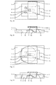
- FIGS. 1A-1D is a top view ( FIGS. 1A and 1C ) as well as a sectional view ( FIGS. 1B, 1D ) a first Embodiment of the motor vehicle key according to the invention shown, wherein in the Figures 1C and 1D a battery 6 is inserted in the holder 5 provided for this purpose.
- a battery 6 is inserted in the holder 5 provided for this purpose.
- the housing is always omitted, in the embodiments shown, the holder is not provided by the housing but by a special component).
- the in the Figures 1A-1D embodiment shown comprises a printed circuit board 1 with a recess 2, which is arranged centrally in the circuit board 1 and this, as it is the FIGS. 1B and 1D can be removed, completely penetrates.
- a holder 5 is arranged, which spans at least a portion of the recess 2.
- the holder 5 is attached to a battery to the circuit board 1;
- the holder may be provided by, for example, the housing or a component attached to the housing.
- a first contact element 3 is fixed with a resilient contact portion 3a, wherein the resilient contact portion 3a comprises two spring arms 3d, at the end region of a spherical formation 3c is formed.
- the resilient contact portion 3a comprises a region 3b, which extends above a plane defined by the surface of the circuit board 1 level E.
- the resilient contact section 3a of the contact element 3 is wave-shaped and is arranged to a large extent with the battery 6 not inserted in the recess 2.
- the resilient contact portion 3a passes into the attachment portion 3e, via which the contact element 3 is mounted on the circuit board 1.
- a further contact element 4 is arranged in the holder 5; the arrangement of the contact element 4 within the motor vehicle key is not essential to the present invention, it is only necessary to ensure that when the battery is inserted a secure contact also takes place via the second contact element 4.
- FIGS 1C and 1D show the same embodiment with inserted or inserted battery 6. Due to the design of the holder, the battery is inserted "from the left" in the holder. Due to the fact that a region 3b of the resilient contact portion 3a extends over the plane E, the resilient contact portion 3a is pressed over the region 3b upon insertion of the battery further into the recess 2, so that when inserted battery 6, the resilient contact portion 3a is completely absorbed by the recess 2 and at the same time the battery 6 is fixed in the holder 5 by the spring force of the resilient contact portion 3a.
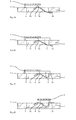
- FIGS. 2A and 2B show a further embodiment of the motor vehicle key according to the invention, wherein in this embodiment, the contact element 3 is designed differently.
- the contact element 3 used in this embodiment is fixed to the underside of the circuit board 1 via its attachment portion 3e, and the resilient contact portion 3a extends through the recess 2, and a portion 3b of the resilient contact portion 3a extends beyond that of the surface of the circuit board 1 defined plane E.
- the holder 5 is further different in that it is "on the other side" of the recess 2 is arranged. This does not change the way it works; when inserted, (which in turn is due to the shape of the holder), the resilient contact portion 3a over the area 3b pressed further into the recess 2 and is fully absorbed by this fully inserted with the battery.
- the resilient contact portion is formed round in the region 3b, so that insertion from both sides is possible.
- Figure 2C shows a further embodiment, which, apart from the positioning of the holder 5, from in the Figures 1A-1D shown embodiment in that the circuit board 1 has a recess 7, in which the mounting portion 3e of the contact element 3 is arranged, wherein the recess 7 is dimensioned such that the mounting portion 3e of the contact element 3 defined by the surface of the circuit board 1 level E. does not exceed, so that it is ensured that even flat components can be installed on the circuit board in this area.
- the recess 2 does not penetrate the circuit board completely, but forms a kind of well in the circuit board 1.
- Such a configuration of the recess 2 has no further effects on the motor vehicle key or its function according to the invention; when inserting a battery, the resilient contact portion 3a of the contact element 3 is pressed over the area 3b in the recess and is completely absorbed by this when the battery 6 is inserted.
- FIG. 3C shows an embodiment in which the contact element 3, in comparison to the previous embodiments, is formed differently.
- the contact element 3 is in turn secured via the attachment region 3e in a recess 7 of the printed circuit board.
- the resilient contact section 3a of the contact element 3 does not extend, or only to a small extent, (in the case of a non-inserted battery) in the recess 2, but extends substantially over the plane defined by the surface of the circuit board 1.
- the resilient contact portion 3a is pressed into the recess 2 and is completely absorbed by the battery 6 when it is inserted.
- FIGS. 4A and 4B show various embodiments of the motor vehicle key according to the invention for use coming contact element 3 with resilient contact portion 3a.
- the resilient contact section 3a of the contact element 3 comprises a spring arm 3d, at the end of which a spherical bulge 3c is arranged.
- the resilient contact portion 3a comprises two spring arms 3d, each with a spherical bulge 3c at the end region of the respective spring arm 3d.
- FIGS. 5A and 5B show different configurations or arrangements of the recess 2 in or at the circuit board 1
- the recess 2 is formed as an incision at an end face of the circuit board, resulting in a U-shaped configuration of the circuit board.
- the lower left corner region of the printed circuit board is cut away.
Landscapes
- Engineering & Computer Science (AREA)
- Manufacturing & Machinery (AREA)
- Physics & Mathematics (AREA)
- General Physics & Mathematics (AREA)
- Chemical & Material Sciences (AREA)
- Chemical Kinetics & Catalysis (AREA)
- Electrochemistry (AREA)
- General Chemical & Material Sciences (AREA)
- Lock And Its Accessories (AREA)
Abstract
Description
- Die vorliegende Erfindung betrifft einen Kraftfahrzeugschlüssel, und insbesondere einen flach bauenden Kraftfahrzeugschlüssel.
- Moderne Kraftfahrzeugschlüssel umfassen üblicherweise eine Leiterplatte, auf welcher zumindest eine elektronische Baugruppe, die regelmäßig eine Sender- und Empfängereinheit aufweist, montiert ist, mittels welcher ein Kraftfahrzeug entriegelt und verriegelt werden kann. Neben diesen grundlegenden Funktionalitäten der elektronischen Baugruppe werden dieser in jüngster Zeit zunehmend weitere Funktionalitäten zugeordnet, so dass es notwendig ist, die Energieversorgung der elektronischen Baugruppe entsprechend anzupassen. Zur Energieversorgung der elektronischen Baugruppe ist üblicherweise eine austauschbare Batterie in dem Schlüssel angeordnet und ist über Kontaktelemente mit der Leiterplatte und damit der elektronischen Baugruppe gekoppelt. Der steigende Energiebedarf der elektronischen Baugruppe bedingt größere Batterien, womit ein Anstieg der Bauhöhe der Batterie einhergeht. Die Batterien sind regelmäßig auf einem Federelement gelagert, welches die Batterie gegen einen Anschlag innerhalb des Kraftfahrzeugschlüssels drückt. Durch den Verbund Feder/Batterie/Anschlag ist eine Mindesthöhe des Kraftfahrzeugschlüssels vorgegeben. Eine übermäßige Bauhöhe des Kraftfahrzeugschlüssels vermindert den Benutzungskomfort und die Möglichkeiten der Aufbewahrung des Kraftfahrzeugschlüssels.
- Es ist daher Aufgabe der vorliegenden Erfindung, einen Kraftfahrzeugschlüssel mit einer geringen Bauhöhe und einem gesteigerten Benutzungskomfort bereitzustellen.
- Diese Aufgabe wird erfindungsgemäß gelöst durch einen Kraftfahrzeugschlüssel mit einer Leiterplatte, welche eine Ausnehmung aufweist. Bei dieser Ausnehmung kann es sich um eine Vertiefung in der Leiterplatte handeln, die Ausnehmung kann aber auch die Leiterplatte vollständig durchdringen, wobei dann im Bereich der Ausnehmung die Leiterplatte vollständig entfernt ist. Die Ausnehmung kann an einer beliebigen Stelle der Leiterplatte angeordnet sein, es kann sich also um eine Durchgangsöffnung oder einen Einschnitt bei der Stirn oder der Längsseite oder bei einer der Ecken handeln.
- Der erfindungsgemäße Kraftfahrzeugschlüssel umfasst ferner eine Halterung für eine Batterie, wobei sich die Halterung zumindest teilweise über der Ausnehmung erstreckt. Bei dieser Halterung kann es sich zum Beispiel um das Gehäuse selber handeln, die Halterung kann aber auch ein gesondertes Bauteil sein, welches an beispielsweise der Leiterplatte oder dem Gehäuse befestigt ist, wobei die Halterung in einem solchen Falle auch einstückig mit den vorgenannten Bauteilen des Kraftfahrzeugschlüssels ausgeführt sein kann. Allgemein kann die Halterung von einem beliebigen Teil des Kraftfahrzeugschlüssels bereitgestellt werden, solange gewährleistet ist, dass sich die Halterung zumindest teilweise über der Ausnehmung erstreckt. Der Kraftfahrzeugschlüssel umfasst ferner Kontaktelemente, die mit der Leiterplatte elektrisch gekoppelt sind, wobei zumindest ein Kontaktelement einen federnden Kontaktabschnitt aufweist, über welchen eine Batterie in der Halterung fixierbar ist. Das Kontaktelement mit dem federnden Kontaktabschnitt ist derart an der Leiterplatte befestigt, dass sich zumindest ein Bereich des federnden Kontaktabschnittes oberhalb einer von der Oberfläche der Leiterplatte definierten Ebene über der Ausnehmung erstreckt. Der verbleibende Bereich des federnden Kontaktabschnittes kann bei nicht eingelegter Batterie in der Ausnehmung oder über dieser angeordnet sein, je nach Ausführung des Kontaktelementes bzw. des federnden Kontaktabschnittes des Kontaktelementes. Wenn eine Batterie in der Halterung angeordnet ist, ist der sich oberhalb der Ebene erstreckende Bereich des federnden Kontaktabschnittes in der Ausnehmung aufgenommen und über diesen Bereich fixiert der federnde Kontaktabschnitt die Batterie in der Halterung. Die Ausführung des weiteren Kontaktelements ist von der genauen Gestaltung des Kraftfahrzeugschlüssels abhängig; das weitere Kontaktelement kann beispielweise in der Halterung angeordnet sein.
- Bei eingelegter Batterie ist der federnde Kontaktabschnitt des Kontaktelementes vollständig in der Ausnehmung aufgenommen, so dass die Batterie, in Abhängigkeit von der genauen Ausgestaltung des Kraftfahrzeugschlüssels, beispielsweise direkt auf der Leiterplatte aufliegt und trotzdem über die Federkraft des federnden Kontaktabschnitts eine Fixierung und Kontaktierung gewährleistet ist. Die Bauhöhe des Kraftfahrzeugschlüssels ist somit vermindert, ohne dass die Kontaktierung oder Lagerung der Batterie in dem Kraftfahrzeugschlüssel nachteilig beeinflusst ist.
- Die genaue Ausgestaltung des federnden Kontaktschnittes ist von dem jeweiligen Anwendungsbereich, der zu verbauenden Batterie sowie der Befestigung an der Leiterplatte abhängig. Es ist jedoch bevorzugt, dass in dem Kontaktbereich federnder Kontaktabschnitt/Batterie der federnde Kontaktabschnitt ballig ausgebildet ist. Die Federkraft des federnden Kontaktabschnittes wirkt somit nur punktuell, was einen optimalen Kontakt zu der Batterie gewährleistet und ferner die Oberfläche der Batterie, über welche sich der ballige Abschnitt bei der Einlegung bzw. Einschiebung der Batterie in die Halterung bewegt, schont.
- Bei einer bevorzugten Ausführungsform des erfindungsgemäßen Kraftfahrzeugschlüssels umfasst der federnde Kontaktabschnitt des Kontaktelementes eine Mehrzahl von Federarmen, wobei der Kontaktbereich eines jeden Federarmes ballig ausgebildet sein kann. In Abhängigkeit von der Ausgestaltung der Batterie sowie der Ausnehmung in der Leiterplatte ist bei einem derart ausgestalteten federnden Kontaktabschnitt die Lage der Batterie in der Halterung gegen ein Verkippen geschützt.
- Die Befestigung des Kontaktelementes mit dem federnden Kontaktabschnitt an der Leiterplatte ist, was die Befestigung als solche angeht, beliebig. So kann beispielsweise ein Befestigungsbereich des Kontaktelementes an der Leiterplatte festgelötet sein, wobei natürlich stets darauf zu achten ist, dass sich ein Bereich des federnden Kontaktabschnittes oberhalb der von der Oberfläche der Leiterplatte definierten Ebene erstreckt.
- In Abhängigkeit von der genauen Ausgestaltung des Kraftfahrzeugschlüssels kann es von Vorteil sein, dass die Leiterplatte eine Aussparung aufweist, in welcher das Kontaktelement über dessen Befestigungsabschnitt befestigt ist, wobei diese Aussparung derart ausgebildet ist, dass der Befestigungsbereich des Kontaktelementes die von der Oberfläche der Leiterplatte gebildeten Ebene nicht überschreitet. Durch diese Maßnahme können in dem Befestigungsbereich auch flache Bauelemente auf der Leiterplatte direkt befestigt werden und den Befestigungsbereich überspannen.
- Wie bereits angedeutet, kann bei speziellen Ausführungsformen des Kraftfahrzeugschlüssels die Batterie direkt auf der Leiterplatte aufliegen. Bei einer bevorzugten Ausführungsform des erfindungsgemäßen Batterieschlüssel ist es daher vorgesehen, dass die Leiterplatte in dem Bereich um die Ausnehmung eine Schutzbeschichtung umfasst, welche die Leiterplatte gegen Beschädigungen durch die Batterie, sei es bei Einlegung oder bei den tagtäglichen geringfügigen Bewegungen in der Halterung, schützt.
- Die Erfindung wird nachfolgend anhand mehrerer bevorzugter Ausführungsformen erläutert, welche in der beiliegenden Zeichnung dargestellt sind, wobei
-
Figuren 1A-1D eine erste Ausführungsform des erfindungsgemäßen Kraftfahrzeugschlüssels zeigen, -
Figuren 2A und 2B eine weitere Ausführungsform des erfindungsgemäßen Kraftfahrzeugschlüssels zeigen, -
Figuren 2C, 2D und3 jeweils eine weitere Ausführungsform des erfindungsgemäßen Kraftfahrzeugschlüssels zeigen, -
Figuren 4A und 4B zwei Ausführungsformen des Kontaktelementes mit federndem Kontaktabschnitt zeigen, und -
Figuren 5A und 5B verschiedene Arten der Ausnehmung und der daraus resultierenden Befestigung eines beispielhaften Kontaktelementes zeigen. - In den
Figuren 1A-1D ist eine Draufsicht (Figur 1A und 1C ) sowie eine Schnittansicht (Figuren 1B, 1D ) einer ersten Ausführungsform des erfindungsgemäßen Kraftfahrzeugschlüssels gezeigt, wobei in denFiguren 1C und 1D eine Batterie 6 in die dafür vorgesehene Halterung 5 eingelegt ist. Bei der nachfolgenden Figurenbeschreibung gilt generell, dass lediglich die für die Erfindung wesentlichen Bauteile des Kraftfahrzeugschlüssels dargestellt sind (beispielsweise ist das Gehäuse stets fortgelassen; bei den gezeigten Ausführungsformen ist die Halterung nicht durch das Gehäuse, sondern durch ein spezielles Bauteil bereitgestellt). Die in denFiguren 1A-1D gezeigte Ausführungsform umfasst eine Leiterplatte 1 mit einer Ausnehmung 2, die mittig in der Leiterplatte 1 angeordnet ist und diese, wie man es denFiguren 1B und 1D entnehmen kann, vollständig durchdringt. Auf der Leiterplatte 1 ist eine Halterung 5 angeordnet, die zumindest einen Abschnitt der Ausnehmung 2 überspannt. Bei dem hier gezeigten Ausführungsbeispiel ist die Halterung 5 für eine Batterie an der Leiterplatte 1 befestigt; bei anderen Ausführungsbeispielen kann, wie bereits angedeutet, die Halterung von beispielsweise dem Gehäuse oder einem an dem Gehäuse befestigten Bauteil bereitgestellt werden. - An der Leiterplatte 1 ist ein erstes Kontaktelement 3 mit einem federnden Kontaktabschnitt 3a befestigt, wobei der federnde Kontaktabschnitt 3a zwei Federarme 3d umfasst, bei deren Endbereich eine ballige Ausbildung 3c ausgeformt ist. Wie der
Figur 1B zu entnehmen ist, umfasst der federnde Kontaktabschnitt 3a einen Bereich 3b, der sich oberhalb einer von der Oberfläche der Leiterplatte 1 definierten Ebene E erstreckt. Bei dem Kontaktelement 3 gemäß der ersten Ausführungsform ist in der Schnittansicht 1B zu erkennen, dass der federnde Kontaktabschnitt 3a des Kontaktelementes 3 wellenförmig ausgebildet ist und zu einem großen Teil bei nicht eingelegter Batterie 6 in der Ausnehmung 2 angeordnet ist. Der federnde Kontaktabschnitt 3a geht über in den Befestigungsabschnitt 3e, über welchen das Kontaktelement 3 auf der Leiterplatte 1 befestigt ist. Bei der gezeigten Ausführungsform ist in der Halterung 5 ein weiteres Kontaktelement 4 angeordnet; die Anordnung des Kontaktelementes 4 innerhalb des Kraftfahrzeugschlüssels ist für die vorliegende Erfindung nicht wesentlich, es ist lediglich sicherzustellen, dass bei eingeschobener Batterie eine sichere Kontaktierung auch über das zweite Kontaktelement 4 stattfindet. - Die
Figuren 1C und 1D zeigen die gleiche Ausführungsform bei eingelegter bzw. eingeschobener Batterie 6. Aufgrund der Ausgestaltung der Halterung wird die Batterie "von links" in die Halterung eingeschoben. Bedingt durch die Tatsache, dass sich ein Bereich 3b des federnden Kontaktabschnittes 3a über die Ebene E erstreckt, wird der federnde Kontaktabschnitt 3a über den Bereich 3b bei Einschieben der Batterie weiter in die Ausnehmung 2 gedrückt, so dass bei eingeschobener Batterie 6 der federnde Kontaktabschnitt 3a vollständig von der Ausnehmung 2 aufgenommen ist und gleichzeitig durch die Federkraft des federnden Kontaktabschnittes 3a die Batterie 6 in der Halterung 5 fixiert ist. Aufgrund der erfindungsgemäßen Ausgestaltung des Kraftfahrzeugschlüssels ist der für die Fixierung der Batterie 6 in der Halterung 5 wichtige federnde Kontaktabschnitt 3a des Kontaktelementes 3 in der Ausnehmung 2 vollständig aufgenommen, so dass das Kontaktelement die Bauhöhe des Kraftfahrzeugschlüssels nicht nachteilig beeinflusst, gleichzeitig aber eine sichere Fixierung der Batterie 6 gewährleistet ist. - Die
Figuren 2A und 2B zeigen eine weitere Ausführungsform des erfindungsgemäßen Kraftfahrzeugschlüssels, wobei bei dieser Ausführungsform das Kontaktelement 3 anders ausgebildet ist. Das bei dieser Ausführungsform verwendete Kontaktelement 3 ist über seinen Befestigungsbereich 3e an der Unterseite der Leiterplatte 1 befestigt, und der federnde Kontaktabschnitt 3a erstreckt sich durch die Ausnehmung 2, und ein Bereich 3b des federnden Kontaktabschnittes 3a erstreckt sich über die von der Oberfläche der Leiterplatte 1 definierte Ebene E. Bei dem gezeigten Ausführungsbeispiel ist ferner die Halterung 5 insofern unterschiedlich, als sie "auf der anderen Seite" der Ausnehmung 2 angeordnet ist. An der Funktionsweise ändert dies nichts; bei Einschub, (der wiederum durch die Gestalt der Halterung bedingt ist) wird der federnde Kontaktabschnitt 3a über den Bereich 3b weiter in die Ausnehmung 2 gedrückt und ist von dieser bei eingelegter Batterie voll umfänglich aufgenommen. - In Abhängigkeit von der "Einschubrichtung" bzw. Montagerichtung der Batterie ist es bevorzugt, dass der federnde Kontaktabschnitt in dem Bereich 3b rundlich ausgebildet ist, so dass ein Einschub von beiden Seiten möglich ist.
-
Figur 2C zeigt eine weitere Ausführungsform, die sich, abgesehen von der Positionierung der Halterung 5, von der in denFiguren 1A-1D gezeigten Ausführungsform dahingehend unterscheidet, dass die Leiterplatte 1 eine Aussparung 7 aufweist, in welcher der Befestigungsbereich 3e des Kontaktelements 3 angeordnet ist, wobei die Aussparung 7 derart dimensioniert ist, dass der Befestigungsbereich 3e des Kontaktelementes 3 die durch die Oberfläche der Leiterplatte 1 definierte Ebene E nicht übersteigt, so dass sichergestellt ist, dass in diesen Bereich auch flache Bauelemente auf der Leiterplatte verbaut werden können. - Bei der in der
Figur 2D gezeigten Ausführungsform durchdringt die Ausnehmung 2 die Leiterplatte nicht vollständig, sondern bildet eine Art Wanne in der Leiterplatte 1. Eine derartige Ausgestaltung der Ausnehmung 2 hat jedoch keine weiteren Auswirkungen auf den erfindungsgemäßen Kraftfahrzeugschlüssel bzw. dessen Funktion; bei Einschieben einer Batterie wird der federnde Kontaktabschnitt 3a des Kontaktelementes 3 über den Bereich 3b in die Ausnehmung gedrückt und ist von dieser bei eingelegter Batterie 6 vollständig aufgenommen. -
Figur 3C zeigt eine Ausführungsform, bei welcher das Kontaktelement 3, im Vergleich zu den vorherigen Ausführungsformen, unterschiedlich ausgebildet ist. Das Kontaktelement 3 ist wiederum über den Befestigungsbereich 3e in einer Aussparung 7 der Leiterplatte befestigt. Der federnde Kontaktabschnitt 3a des Kontaktelementes 3 erstreckt sich jedoch nicht, oder nur in geringem Maße, (bei nicht eingelegter Batterie) in der Ausnehmung 2, sondern erstreckt sich im Wesentlichen über der durch die Oberfläche der Leiterplatte 1 definierten Ebene. Bei Einlegen einer Batterie 6 wird aber auch bei dieser Ausführungsform der federnde Kontaktabschnitt 3a in die Ausnehmung 2 gedrückt und ist bei eingelegter Batterie 6 von dieser vollständig aufgenommen. - Die
Figuren 4A und 4B zeigen verschiedene Ausführungsformen des bei dem erfindungsgemäßen Kraftfahrzeugschlüssel zur Anwendung kommenden Kontaktelementes 3 mit federndem Kontaktabschnitt 3a. Bei der inFigur 4A gezeigten Ausführungsform umfasst der federnde Kontaktabschnitt 3a des Kontaktelementes 3 einen Federarm 3d, an dessen Ende eine ballige Ausbuchtung 3c angeordnet ist. Bei der inFigur 4B gezeigten Ausführungsform (die bei den Ausführungsformen derFiguren 1A-1D ,2A und 2B, 2C und 2D bereits dargestellt wurde), umfasst der federnde Kontaktabschnitt 3a zwei Federarme 3d mit jeweils einer balligen Ausbuchtung 3c bei dem Endbereich des jeweiligen Federarms 3d. - Die
Figuren 5A und 5B zeigen unterschiedliche Konfigurationen bzw. Anordnungen der Ausnehmung 2 in bzw. bei der Leiterplatte 1. Bei der inFigur 5A gezeigten Ausführungsform ist die Ausnehmung 2 als Einschnitt bei einer Stirnseite der Leiterplatte ausgebildet, was in einer U-förmigen Gestalt der Leiterplatte resultiert. Bei der inFigur 5B gezeigten Ausführungsform ist der untere linke Eckbereich der Leiterplatte weggeschnitten. - Die vorstehend beschriebene Erfindung ist nicht auf die im Detail beschriebenen und dargestellten Ausführungsformen beschränkt. Es ist ersichtlich, dass an der in der Zeichnung dargestellten Ausführungsformen zahlreiche, dem Fachmann entsprechend der beabsichtigten Anwendung naheliegende Änderungen vorgenommen werden können, ohne dass dadurch der Schutzbereich der Erfindung verlassen wird. So sind insbesondere bei der Ausgestaltung des Kontaktelementes mit federndem Kontaktbereich sowie der Anordnung und Befestigung an der Leiterplatte zahlreiche Variationen möglich.
Claims (5)
- Kraftfahrzeugschlüssel mit
einer Leiterplatte (1) mit einer Ausnehmung (2),
einer Halterung (5) für eine Batterie (6), wobei sich die Halterung (5) zumindest teilweise über der Ausnehmung (2) erstreckt, und
Kontaktelementen (3, 4), die mit der Leiterplatte (1) elektrisch gekoppelt sind, wobei ein Kontaktelement (3) einen federnden Kontaktabschnitt (3a) aufweist, über welchen eine Batterie (6) in der Halterung (5) fixierbar ist,
dadurch gekennzeichnet, dass das Kontaktelement mit dem federnden Kontaktabschnitt derart an der Leiterplatte (1) befestigt ist, dass sich ein Bereich (3b) des federnden Kontaktabschnitts (3a) oberhalb einer von der Oberfläche der Leiterplatte (1) definierten Ebene über der Ausnehmung (2) erstreckt und zumindest dieser Bereich (3b) in der Ausnehmung (2) aufgenommen ist, wenn eine Batterie (6) in der Halterung (5) angeordnet ist und von dem federnden Kontaktabschnitt (3a) in dieser fixiert ist. - Kraftfahrzeugschlüssel nach Anspruch 1, dadurch gekennzeichnet, dass der federnde Kontaktabschnitt (3a) eine Mehrzahl von Federarmen (3d) umfasst.
- Kraftfahrzeugschlüssel nach Anspruch 1 oder 2, dadurch gekennzeichnet, dass der federnde Kontaktabschnitt (3a) in einem Kontaktbereich (3c) ballig ausgebildet ist.
- Kraftfahrzeugschlüssel nach einem der Ansprüche 1 - 3, dadurch gekennzeichnet, dass der Leiterplatte (1) eine Aussparung (7) aufweist, in welcher das Kontaktelement (3) befestigt ist, wobei die Aussparung (7) derart ausgebildet ist, dass der Befestigungsbereich (3e) des Kontaktelementes (3) die von der Oberfläche der Leiterplatte (1) gebildet Ebene nicht überschreitet.
- Kraftfahrzeugschlüssel nach einem der Ansprüche 1 - 4, dadurch gekennzeichnet, dass die Leiterplatte (1) in dem Bereich um die Ausnehmung eine Schutzbeschichtung umfasst.
Priority Applications (1)
| Application Number | Priority Date | Filing Date | Title |
|---|---|---|---|
| EP17170548.6A EP3239936A1 (de) | 2012-07-20 | 2013-06-12 | Flacher kraftfahrzeugschlüssel |
Applications Claiming Priority (1)
| Application Number | Priority Date | Filing Date | Title |
|---|---|---|---|
| DE102012106622.1A DE102012106622A1 (de) | 2012-07-20 | 2012-07-20 | Flacher Kraftfahrzeugschlüssel |
Related Child Applications (2)
| Application Number | Title | Priority Date | Filing Date |
|---|---|---|---|
| EP17170548.6A Division EP3239936A1 (de) | 2012-07-20 | 2013-06-12 | Flacher kraftfahrzeugschlüssel |
| EP17170548.6A Division-Into EP3239936A1 (de) | 2012-07-20 | 2013-06-12 | Flacher kraftfahrzeugschlüssel |
Publications (2)
| Publication Number | Publication Date |
|---|---|
| EP2688048A1 true EP2688048A1 (de) | 2014-01-22 |
| EP2688048B1 EP2688048B1 (de) | 2017-08-09 |
Family
ID=48578909
Family Applications (2)
| Application Number | Title | Priority Date | Filing Date |
|---|---|---|---|
| EP13171640.9A Active EP2688048B1 (de) | 2012-07-20 | 2013-06-12 | Flacher Kraftfahrzeugschlüssel |
| EP17170548.6A Withdrawn EP3239936A1 (de) | 2012-07-20 | 2013-06-12 | Flacher kraftfahrzeugschlüssel |
Family Applications After (1)
| Application Number | Title | Priority Date | Filing Date |
|---|---|---|---|
| EP17170548.6A Withdrawn EP3239936A1 (de) | 2012-07-20 | 2013-06-12 | Flacher kraftfahrzeugschlüssel |
Country Status (4)
| Country | Link |
|---|---|
| US (1) | US9540846B2 (de) |
| EP (2) | EP2688048B1 (de) |
| CN (1) | CN103578166B (de) |
| DE (1) | DE102012106622A1 (de) |
Families Citing this family (8)
| Publication number | Priority date | Publication date | Assignee | Title |
|---|---|---|---|---|
| DE102015105009A1 (de) | 2014-12-04 | 2016-06-09 | Huf Hülsbeck & Fürst Gmbh & Co. Kg | Kraftfahrzeugschlüssel |
| JP6805540B2 (ja) * | 2016-05-02 | 2020-12-23 | オムロン株式会社 | 板バネの固定構造及び電気接点構造の製造方法 |
| KR101853764B1 (ko) | 2017-11-23 | 2018-05-02 | 콘티넨탈 오토모티브 게엠베하 | 파손 방지형 카드키 |
| KR101853765B1 (ko) | 2017-11-23 | 2018-05-02 | 콘티넨탈 오토모티브 게엠베하 | 차량용 스마트키 |
| KR101853763B1 (ko) | 2017-11-24 | 2018-05-02 | 콘티넨탈 오토모티브 게엠베하 | 카드형 스마트키 |
| JP6978920B2 (ja) | 2017-12-13 | 2021-12-08 | Fdk株式会社 | 電池モジュール |
| JP2024017348A (ja) * | 2022-07-27 | 2024-02-08 | 富士通コンポーネント株式会社 | 電子製品 |
| JP2024017347A (ja) | 2022-07-27 | 2024-02-08 | 富士通コンポーネント株式会社 | 電子機器の筐体 |
Citations (5)
| Publication number | Priority date | Publication date | Assignee | Title |
|---|---|---|---|---|
| WO1996010899A1 (en) * | 1994-09-30 | 1996-04-11 | Berg Technology, Inc. | Memory card assembly having grounded wiring board |
| DE102006019690A1 (de) * | 2005-04-28 | 2006-11-23 | Denso Corp., Kariya | Drahtlose Kommunikationsvorrichtung sowie Herstellungsverfahren hierfür |
| DE102006018900A1 (de) * | 2005-04-27 | 2006-11-23 | Denso Corp., Kariya | Drahtlostransceiver und Herstellungsverfahren hierfür |
| US20090017778A1 (en) * | 2007-07-13 | 2009-01-15 | Fujitsu Component Limited | Transceiver |
| US20130039024A1 (en) * | 2011-08-10 | 2013-02-14 | Denso Corporation | Card key |
Family Cites Families (15)
| Publication number | Priority date | Publication date | Assignee | Title |
|---|---|---|---|---|
| US4276582A (en) * | 1978-12-26 | 1981-06-30 | Lock Light Corporation | Key with light |
| DE3330179A1 (de) * | 1983-08-20 | 1985-04-04 | Heinz 5067 Kürten Wolter | Mit einem schluessel verbindbare leuchte |
| US5157244A (en) * | 1989-12-19 | 1992-10-20 | Amp Incorporated | Smart key system |
| US5652587A (en) * | 1995-01-24 | 1997-07-29 | Liu; Chang-Jen | Remote control device having means therein for storage of a hand tool |
| FR2791097B1 (fr) * | 1999-03-17 | 2001-05-11 | Siemens Automotive Sa | Dispositif adapte a limiter le flechissement d'un moyen flexible, et boitier de cle le comportant |
| US6852929B2 (en) * | 2002-11-27 | 2005-02-08 | Lear Corporation | Elastomer seal and housing for a remote keyless entry device |
| JP2005179942A (ja) * | 2003-12-17 | 2005-07-07 | Denso Corp | 自動車用ワイヤレス送受信機 |
| EP1659659A1 (de) * | 2004-11-23 | 2006-05-24 | Huf Hülsbeck & Fürst GmbH & Co. KG | Halte- und Kontaktiervorrichtung für eine Knopfzelle und Verfahren zur Herstellung einer solchen |
| US7463134B1 (en) * | 2005-04-01 | 2008-12-09 | Stilley Russell L | Dual key fob |
| FR2954009B1 (fr) * | 2009-12-12 | 2012-07-13 | Johnson Controls Tech Co | Module mecanique et cle. |
| JP5480043B2 (ja) * | 2010-07-08 | 2014-04-23 | 株式会社東海理化電機製作所 | 携帯機 |
| JP5163776B2 (ja) * | 2010-07-13 | 2013-03-13 | 株式会社デンソー | カードキー |
| US20120087096A1 (en) * | 2010-10-07 | 2012-04-12 | Chu-Ping Shen | Power Structure of Electronic Products |
| JP5685209B2 (ja) * | 2012-01-24 | 2015-03-18 | 株式会社東海理化電機製作所 | 電池ホルダ |
| US20140190737A1 (en) * | 2013-01-08 | 2014-07-10 | Advance Security Inc | Remote Controller Casing |
-
2012
- 2012-07-20 DE DE102012106622.1A patent/DE102012106622A1/de not_active Withdrawn
-
2013
- 2013-06-12 EP EP13171640.9A patent/EP2688048B1/de active Active
- 2013-06-12 EP EP17170548.6A patent/EP3239936A1/de not_active Withdrawn
- 2013-07-03 CN CN201310277276.XA patent/CN103578166B/zh active Active
- 2013-07-15 US US13/941,720 patent/US9540846B2/en active Active
Patent Citations (5)
| Publication number | Priority date | Publication date | Assignee | Title |
|---|---|---|---|---|
| WO1996010899A1 (en) * | 1994-09-30 | 1996-04-11 | Berg Technology, Inc. | Memory card assembly having grounded wiring board |
| DE102006018900A1 (de) * | 2005-04-27 | 2006-11-23 | Denso Corp., Kariya | Drahtlostransceiver und Herstellungsverfahren hierfür |
| DE102006019690A1 (de) * | 2005-04-28 | 2006-11-23 | Denso Corp., Kariya | Drahtlose Kommunikationsvorrichtung sowie Herstellungsverfahren hierfür |
| US20090017778A1 (en) * | 2007-07-13 | 2009-01-15 | Fujitsu Component Limited | Transceiver |
| US20130039024A1 (en) * | 2011-08-10 | 2013-02-14 | Denso Corporation | Card key |
Also Published As
| Publication number | Publication date |
|---|---|
| CN103578166A (zh) | 2014-02-12 |
| US9540846B2 (en) | 2017-01-10 |
| DE102012106622A1 (de) | 2014-01-23 |
| EP3239936A1 (de) | 2017-11-01 |
| US20140021025A1 (en) | 2014-01-23 |
| EP2688048B1 (de) | 2017-08-09 |
| CN103578166B (zh) | 2018-02-09 |
Similar Documents
| Publication | Publication Date | Title |
|---|---|---|
| EP2688048B1 (de) | Flacher Kraftfahrzeugschlüssel | |
| DE102017129402B4 (de) | Leiterplattengehäuse mit führungsrippen | |
| DE102009046014A1 (de) | Elektrisches Verbindergehäuse und Verfahren zu dessen Zusammenbau | |
| DE102009050523B4 (de) | Induktionsspule | |
| DE10006530A1 (de) | Antennenfeder | |
| DE112014002529B4 (de) | Elektronische steuereinheit und schutzgehäuse | |
| DE102009015312A1 (de) | Elektronische Vorrichtung, die eine Leiterplatte mit Abstrahlungselement umfasst, Hydraulikeinheit, die die elektronische Vorrichtung umfasst, und Verfahren zum Befestigen des Abstrahlungselements an der Leiterplatte | |
| DE102018101667B3 (de) | Steckverbinder mit Sekundärsicherung | |
| DE2911972A1 (de) | Anschlussklemme, vorzugsweise zum einbau auf leiterplatten von gedruckten schaltungen | |
| EP3378289B1 (de) | Leiterplatte zum mechanischen fixieren eines gehäuses | |
| DE102005047484A1 (de) | Auf einem Fahrzeug angeordnete Antennenvorrichtung | |
| WO2018219769A1 (de) | Bauteilhaltevorrichtung | |
| DE102009058181B4 (de) | Träger für Leiterplatte | |
| DE9112605U1 (de) | Kontaktvorrichtung für batteriegespeiste, elektrische Geräte | |
| DE102004060302A1 (de) | Anordnung für ein elektronisches Steuergerät | |
| DE102005043660A1 (de) | Kartenverbinder | |
| DE102018218648A1 (de) | Einpressanschluss und Einpressanschluss-Verbindungsstruktur einer Leiterplatte | |
| EP1185998B1 (de) | Vorrichtung zur lagerichtigen befestigung einer leiterplatte | |
| DE102019125797B4 (de) | Montagevorrichtung | |
| DE112015006767T5 (de) | Gehäuse einer elektronischen Vorrichtung | |
| DE102014107831B4 (de) | Klappdeckel | |
| EP3227863B1 (de) | Kraftfahrzeugschlüssel | |
| EP3816533B1 (de) | Durchlauferhitzer mit einem gehäuse | |
| EP2026415B1 (de) | Kontaktsystem, Verfahren zum Herstellen eines Kontaktsystems, Steckeraufnahmevorrichtung und Verwendung einer Steckeraufnahmevorrichtung | |
| DE10126330C2 (de) | Einschubkarte |
Legal Events
| Date | Code | Title | Description |
|---|---|---|---|
| PUAI | Public reference made under article 153(3) epc to a published international application that has entered the european phase |
Free format text: ORIGINAL CODE: 0009012 |
|
| AK | Designated contracting states |
Kind code of ref document: A1 Designated state(s): AL AT BE BG CH CY CZ DE DK EE ES FI FR GB GR HR HU IE IS IT LI LT LU LV MC MK MT NL NO PL PT RO RS SE SI SK SM TR |
|
| AX | Request for extension of the european patent |
Extension state: BA ME |
|
| 17P | Request for examination filed |
Effective date: 20140625 |
|
| RBV | Designated contracting states (corrected) |
Designated state(s): AL AT BE BG CH CY CZ DE DK EE ES FI FR GB GR HR HU IE IS IT LI LT LU LV MC MK MT NL NO PL PT RO RS SE SI SK SM TR |
|
| 17Q | First examination report despatched |
Effective date: 20160316 |
|
| GRAP | Despatch of communication of intention to grant a patent |
Free format text: ORIGINAL CODE: EPIDOSNIGR1 |
|
| STAA | Information on the status of an ep patent application or granted ep patent |
Free format text: STATUS: GRANT OF PATENT IS INTENDED |
|
| INTG | Intention to grant announced |
Effective date: 20170303 |
|
| GRAS | Grant fee paid |
Free format text: ORIGINAL CODE: EPIDOSNIGR3 |
|
| GRAA | (expected) grant |
Free format text: ORIGINAL CODE: 0009210 |
|
| STAA | Information on the status of an ep patent application or granted ep patent |
Free format text: STATUS: THE PATENT HAS BEEN GRANTED |
|
| AK | Designated contracting states |
Kind code of ref document: B1 Designated state(s): AL AT BE BG CH CY CZ DE DK EE ES FI FR GB GR HR HU IE IS IT LI LT LU LV MC MK MT NL NO PL PT RO RS SE SI SK SM TR |
|
| REG | Reference to a national code |
Ref country code: GB Ref legal event code: FG4D Free format text: NOT ENGLISH |
|
| REG | Reference to a national code |
Ref country code: CH Ref legal event code: EP Ref country code: AT Ref legal event code: REF Ref document number: 917599 Country of ref document: AT Kind code of ref document: T Effective date: 20170815 |
|
| REG | Reference to a national code |
Ref country code: IE Ref legal event code: FG4D Free format text: LANGUAGE OF EP DOCUMENT: GERMAN |
|
| REG | Reference to a national code |
Ref country code: DE Ref legal event code: R096 Ref document number: 502013007986 Country of ref document: DE |
|
| REG | Reference to a national code |
Ref country code: NL Ref legal event code: MP Effective date: 20170809 |
|
| REG | Reference to a national code |
Ref country code: LT Ref legal event code: MG4D |
|
| PG25 | Lapsed in a contracting state [announced via postgrant information from national office to epo] |
Ref country code: NL Free format text: LAPSE BECAUSE OF FAILURE TO SUBMIT A TRANSLATION OF THE DESCRIPTION OR TO PAY THE FEE WITHIN THE PRESCRIBED TIME-LIMIT Effective date: 20170809 Ref country code: NO Free format text: LAPSE BECAUSE OF FAILURE TO SUBMIT A TRANSLATION OF THE DESCRIPTION OR TO PAY THE FEE WITHIN THE PRESCRIBED TIME-LIMIT Effective date: 20171109 Ref country code: SE Free format text: LAPSE BECAUSE OF FAILURE TO SUBMIT A TRANSLATION OF THE DESCRIPTION OR TO PAY THE FEE WITHIN THE PRESCRIBED TIME-LIMIT Effective date: 20170809 Ref country code: LT Free format text: LAPSE BECAUSE OF FAILURE TO SUBMIT A TRANSLATION OF THE DESCRIPTION OR TO PAY THE FEE WITHIN THE PRESCRIBED TIME-LIMIT Effective date: 20170809 Ref country code: FI Free format text: LAPSE BECAUSE OF FAILURE TO SUBMIT A TRANSLATION OF THE DESCRIPTION OR TO PAY THE FEE WITHIN THE PRESCRIBED TIME-LIMIT Effective date: 20170809 Ref country code: HR Free format text: LAPSE BECAUSE OF FAILURE TO SUBMIT A TRANSLATION OF THE DESCRIPTION OR TO PAY THE FEE WITHIN THE PRESCRIBED TIME-LIMIT Effective date: 20170809 |
|
| PG25 | Lapsed in a contracting state [announced via postgrant information from national office to epo] |
Ref country code: PL Free format text: LAPSE BECAUSE OF FAILURE TO SUBMIT A TRANSLATION OF THE DESCRIPTION OR TO PAY THE FEE WITHIN THE PRESCRIBED TIME-LIMIT Effective date: 20170809 Ref country code: GR Free format text: LAPSE BECAUSE OF FAILURE TO SUBMIT A TRANSLATION OF THE DESCRIPTION OR TO PAY THE FEE WITHIN THE PRESCRIBED TIME-LIMIT Effective date: 20171110 Ref country code: BG Free format text: LAPSE BECAUSE OF FAILURE TO SUBMIT A TRANSLATION OF THE DESCRIPTION OR TO PAY THE FEE WITHIN THE PRESCRIBED TIME-LIMIT Effective date: 20171109 Ref country code: ES Free format text: LAPSE BECAUSE OF FAILURE TO SUBMIT A TRANSLATION OF THE DESCRIPTION OR TO PAY THE FEE WITHIN THE PRESCRIBED TIME-LIMIT Effective date: 20170809 Ref country code: RS Free format text: LAPSE BECAUSE OF FAILURE TO SUBMIT A TRANSLATION OF THE DESCRIPTION OR TO PAY THE FEE WITHIN THE PRESCRIBED TIME-LIMIT Effective date: 20170809 Ref country code: LV Free format text: LAPSE BECAUSE OF FAILURE TO SUBMIT A TRANSLATION OF THE DESCRIPTION OR TO PAY THE FEE WITHIN THE PRESCRIBED TIME-LIMIT Effective date: 20170809 Ref country code: IS Free format text: LAPSE BECAUSE OF FAILURE TO SUBMIT A TRANSLATION OF THE DESCRIPTION OR TO PAY THE FEE WITHIN THE PRESCRIBED TIME-LIMIT Effective date: 20171209 |
|
| PG25 | Lapsed in a contracting state [announced via postgrant information from national office to epo] |
Ref country code: DK Free format text: LAPSE BECAUSE OF FAILURE TO SUBMIT A TRANSLATION OF THE DESCRIPTION OR TO PAY THE FEE WITHIN THE PRESCRIBED TIME-LIMIT Effective date: 20170809 Ref country code: CZ Free format text: LAPSE BECAUSE OF FAILURE TO SUBMIT A TRANSLATION OF THE DESCRIPTION OR TO PAY THE FEE WITHIN THE PRESCRIBED TIME-LIMIT Effective date: 20170809 Ref country code: RO Free format text: LAPSE BECAUSE OF FAILURE TO SUBMIT A TRANSLATION OF THE DESCRIPTION OR TO PAY THE FEE WITHIN THE PRESCRIBED TIME-LIMIT Effective date: 20170809 |
|
| REG | Reference to a national code |
Ref country code: DE Ref legal event code: R097 Ref document number: 502013007986 Country of ref document: DE |
|
| PG25 | Lapsed in a contracting state [announced via postgrant information from national office to epo] |
Ref country code: SK Free format text: LAPSE BECAUSE OF FAILURE TO SUBMIT A TRANSLATION OF THE DESCRIPTION OR TO PAY THE FEE WITHIN THE PRESCRIBED TIME-LIMIT Effective date: 20170809 Ref country code: IT Free format text: LAPSE BECAUSE OF FAILURE TO SUBMIT A TRANSLATION OF THE DESCRIPTION OR TO PAY THE FEE WITHIN THE PRESCRIBED TIME-LIMIT Effective date: 20170809 Ref country code: EE Free format text: LAPSE BECAUSE OF FAILURE TO SUBMIT A TRANSLATION OF THE DESCRIPTION OR TO PAY THE FEE WITHIN THE PRESCRIBED TIME-LIMIT Effective date: 20170809 Ref country code: SM Free format text: LAPSE BECAUSE OF FAILURE TO SUBMIT A TRANSLATION OF THE DESCRIPTION OR TO PAY THE FEE WITHIN THE PRESCRIBED TIME-LIMIT Effective date: 20170809 |
|
| PLBE | No opposition filed within time limit |
Free format text: ORIGINAL CODE: 0009261 |
|
| STAA | Information on the status of an ep patent application or granted ep patent |
Free format text: STATUS: NO OPPOSITION FILED WITHIN TIME LIMIT |
|
| REG | Reference to a national code |
Ref country code: FR Ref legal event code: PLFP Year of fee payment: 6 |
|
| 26N | No opposition filed |
Effective date: 20180511 |
|
| PG25 | Lapsed in a contracting state [announced via postgrant information from national office to epo] |
Ref country code: SI Free format text: LAPSE BECAUSE OF FAILURE TO SUBMIT A TRANSLATION OF THE DESCRIPTION OR TO PAY THE FEE WITHIN THE PRESCRIBED TIME-LIMIT Effective date: 20170809 |
|
| PG25 | Lapsed in a contracting state [announced via postgrant information from national office to epo] |
Ref country code: MT Free format text: LAPSE BECAUSE OF FAILURE TO SUBMIT A TRANSLATION OF THE DESCRIPTION OR TO PAY THE FEE WITHIN THE PRESCRIBED TIME-LIMIT Effective date: 20170809 |
|
| REG | Reference to a national code |
Ref country code: CH Ref legal event code: PL |
|
| REG | Reference to a national code |
Ref country code: BE Ref legal event code: MM Effective date: 20180630 |
|
| REG | Reference to a national code |
Ref country code: IE Ref legal event code: MM4A |
|
| PG25 | Lapsed in a contracting state [announced via postgrant information from national office to epo] |
Ref country code: MC Free format text: LAPSE BECAUSE OF FAILURE TO SUBMIT A TRANSLATION OF THE DESCRIPTION OR TO PAY THE FEE WITHIN THE PRESCRIBED TIME-LIMIT Effective date: 20170809 Ref country code: LU Free format text: LAPSE BECAUSE OF NON-PAYMENT OF DUE FEES Effective date: 20180612 |
|
| PG25 | Lapsed in a contracting state [announced via postgrant information from national office to epo] |
Ref country code: LI Free format text: LAPSE BECAUSE OF NON-PAYMENT OF DUE FEES Effective date: 20180630 Ref country code: IE Free format text: LAPSE BECAUSE OF NON-PAYMENT OF DUE FEES Effective date: 20180612 Ref country code: CH Free format text: LAPSE BECAUSE OF NON-PAYMENT OF DUE FEES Effective date: 20180630 |
|
| PG25 | Lapsed in a contracting state [announced via postgrant information from national office to epo] |
Ref country code: BE Free format text: LAPSE BECAUSE OF NON-PAYMENT OF DUE FEES Effective date: 20180630 |
|
| REG | Reference to a national code |
Ref country code: AT Ref legal event code: MM01 Ref document number: 917599 Country of ref document: AT Kind code of ref document: T Effective date: 20180612 |
|
| PG25 | Lapsed in a contracting state [announced via postgrant information from national office to epo] |
Ref country code: AT Free format text: LAPSE BECAUSE OF NON-PAYMENT OF DUE FEES Effective date: 20180612 |
|
| PG25 | Lapsed in a contracting state [announced via postgrant information from national office to epo] |
Ref country code: TR Free format text: LAPSE BECAUSE OF FAILURE TO SUBMIT A TRANSLATION OF THE DESCRIPTION OR TO PAY THE FEE WITHIN THE PRESCRIBED TIME-LIMIT Effective date: 20170809 |
|
| PG25 | Lapsed in a contracting state [announced via postgrant information from national office to epo] |
Ref country code: HU Free format text: LAPSE BECAUSE OF FAILURE TO SUBMIT A TRANSLATION OF THE DESCRIPTION OR TO PAY THE FEE WITHIN THE PRESCRIBED TIME-LIMIT; INVALID AB INITIO Effective date: 20130612 Ref country code: PT Free format text: LAPSE BECAUSE OF FAILURE TO SUBMIT A TRANSLATION OF THE DESCRIPTION OR TO PAY THE FEE WITHIN THE PRESCRIBED TIME-LIMIT Effective date: 20170809 |
|
| PG25 | Lapsed in a contracting state [announced via postgrant information from national office to epo] |
Ref country code: MK Free format text: LAPSE BECAUSE OF NON-PAYMENT OF DUE FEES Effective date: 20170809 Ref country code: CY Free format text: LAPSE BECAUSE OF FAILURE TO SUBMIT A TRANSLATION OF THE DESCRIPTION OR TO PAY THE FEE WITHIN THE PRESCRIBED TIME-LIMIT Effective date: 20170809 |
|
| PG25 | Lapsed in a contracting state [announced via postgrant information from national office to epo] |
Ref country code: AL Free format text: LAPSE BECAUSE OF FAILURE TO SUBMIT A TRANSLATION OF THE DESCRIPTION OR TO PAY THE FEE WITHIN THE PRESCRIBED TIME-LIMIT Effective date: 20170809 |
|
| P01 | Opt-out of the competence of the unified patent court (upc) registered |
Effective date: 20230507 |
|
| PGFP | Annual fee paid to national office [announced via postgrant information from national office to epo] |
Ref country code: DE Payment date: 20250630 Year of fee payment: 13 |
|
| PGFP | Annual fee paid to national office [announced via postgrant information from national office to epo] |
Ref country code: GB Payment date: 20250620 Year of fee payment: 13 |
|
| PGFP | Annual fee paid to national office [announced via postgrant information from national office to epo] |
Ref country code: FR Payment date: 20250626 Year of fee payment: 13 |
|
| REG | Reference to a national code |
Ref country code: DE Ref legal event code: R084 Ref document number: 502013007986 Country of ref document: DE |