EP2687822A2 - Positionsmesseinrichtung - Google Patents
Positionsmesseinrichtung Download PDFInfo
- Publication number
- EP2687822A2 EP2687822A2 EP13168915.0A EP13168915A EP2687822A2 EP 2687822 A2 EP2687822 A2 EP 2687822A2 EP 13168915 A EP13168915 A EP 13168915A EP 2687822 A2 EP2687822 A2 EP 2687822A2
- Authority
- EP
- European Patent Office
- Prior art keywords
- code
- incremental
- measuring device
- position measuring
- track
- Prior art date
- Legal status (The legal status is an assumption and is not a legal conclusion. Google has not performed a legal analysis and makes no representation as to the accuracy of the status listed.)
- Granted
Links
- 230000000295 complement effect Effects 0.000 claims abstract description 12
- 230000000737 periodic effect Effects 0.000 claims description 31
- 238000011156 evaluation Methods 0.000 claims description 23
- 101100152436 Saccharomyces cerevisiae (strain ATCC 204508 / S288c) TAT2 gene Proteins 0.000 claims description 4
- 230000003287 optical effect Effects 0.000 claims description 4
- 238000005070 sampling Methods 0.000 abstract description 12
- 238000005259 measurement Methods 0.000 description 7
- 230000001419 dependent effect Effects 0.000 description 6
- 238000009826 distribution Methods 0.000 description 3
- 230000015572 biosynthetic process Effects 0.000 description 1
- 238000001914 filtration Methods 0.000 description 1
Images
Classifications
-
- G—PHYSICS
- G01—MEASURING; TESTING
- G01D—MEASURING NOT SPECIALLY ADAPTED FOR A SPECIFIC VARIABLE; ARRANGEMENTS FOR MEASURING TWO OR MORE VARIABLES NOT COVERED IN A SINGLE OTHER SUBCLASS; TARIFF METERING APPARATUS; MEASURING OR TESTING NOT OTHERWISE PROVIDED FOR
- G01D5/00—Mechanical means for transferring the output of a sensing member; Means for converting the output of a sensing member to another variable where the form or nature of the sensing member does not constrain the means for converting; Transducers not specially adapted for a specific variable
- G01D5/12—Mechanical means for transferring the output of a sensing member; Means for converting the output of a sensing member to another variable where the form or nature of the sensing member does not constrain the means for converting; Transducers not specially adapted for a specific variable using electric or magnetic means
- G01D5/244—Mechanical means for transferring the output of a sensing member; Means for converting the output of a sensing member to another variable where the form or nature of the sensing member does not constrain the means for converting; Transducers not specially adapted for a specific variable using electric or magnetic means influencing characteristics of pulses or pulse trains; generating pulses or pulse trains
- G01D5/245—Mechanical means for transferring the output of a sensing member; Means for converting the output of a sensing member to another variable where the form or nature of the sensing member does not constrain the means for converting; Transducers not specially adapted for a specific variable using electric or magnetic means influencing characteristics of pulses or pulse trains; generating pulses or pulse trains using a variable number of pulses in a train
- G01D5/2454—Encoders incorporating incremental and absolute signals
- G01D5/2455—Encoders incorporating incremental and absolute signals with incremental and absolute tracks on the same encoder
-
- G—PHYSICS
- G01—MEASURING; TESTING
- G01D—MEASURING NOT SPECIALLY ADAPTED FOR A SPECIFIC VARIABLE; ARRANGEMENTS FOR MEASURING TWO OR MORE VARIABLES NOT COVERED IN A SINGLE OTHER SUBCLASS; TARIFF METERING APPARATUS; MEASURING OR TESTING NOT OTHERWISE PROVIDED FOR
- G01D5/00—Mechanical means for transferring the output of a sensing member; Means for converting the output of a sensing member to another variable where the form or nature of the sensing member does not constrain the means for converting; Transducers not specially adapted for a specific variable
- G01D5/26—Mechanical means for transferring the output of a sensing member; Means for converting the output of a sensing member to another variable where the form or nature of the sensing member does not constrain the means for converting; Transducers not specially adapted for a specific variable characterised by optical transfer means, i.e. using infrared, visible, or ultraviolet light
- G01D5/32—Mechanical means for transferring the output of a sensing member; Means for converting the output of a sensing member to another variable where the form or nature of the sensing member does not constrain the means for converting; Transducers not specially adapted for a specific variable characterised by optical transfer means, i.e. using infrared, visible, or ultraviolet light with attenuation or whole or partial obturation of beams of light
- G01D5/34—Mechanical means for transferring the output of a sensing member; Means for converting the output of a sensing member to another variable where the form or nature of the sensing member does not constrain the means for converting; Transducers not specially adapted for a specific variable characterised by optical transfer means, i.e. using infrared, visible, or ultraviolet light with attenuation or whole or partial obturation of beams of light the beams of light being detected by photocells
- G01D5/347—Mechanical means for transferring the output of a sensing member; Means for converting the output of a sensing member to another variable where the form or nature of the sensing member does not constrain the means for converting; Transducers not specially adapted for a specific variable characterised by optical transfer means, i.e. using infrared, visible, or ultraviolet light with attenuation or whole or partial obturation of beams of light the beams of light being detected by photocells using displacement encoding scales
- G01D5/34776—Absolute encoders with analogue or digital scales
Definitions
- the invention relates to a position measuring device for determining the absolute position.
- absolute position measuring devices are increasingly used, in which the absolute position information is derived from a code track with code elements arranged one behind the other in the measuring direction.
- the code elements are provided in pseudo-random distribution, so that a certain number of successive code elements each forms a bit pattern.
- Such a sequential code is called chain code or pseudo-random code (PRC).
- an absolute position measuring device from which this invention proceeds, is in the EP 2 416 126 A1 described.
- the position measuring device on a code carrier with a code track, which consists of a sequence of successively arranged in the measuring direction code elements.
- a periodic incremental graduation is arranged in a parallel to the code track arranged track.
- Detectors of a scanning device in each case jointly scan the code track and the incremental graduation and thus generate a common scanning signal from the two tracks. This scanning signal is fed to an evaluation unit which forms a code information and a periodic incremental signal therefrom.
- the disadvantage here is the relatively low degree of modulation of the scanning signals and the relatively complex evaluation.
- the invention has for its object to provide an absolute position measuring device, with a simple way a correct absolute position with high reliability and at least one periodic incremental signal can be generated.
- the design of the code elements is selected in a known manner depending on the scanning principle.
- the code elements can be optically, magnetically, capacitively or inductively scanned. According to the design of the code elements and the detectors are selected.
- complementary properties mean that the subregions of the code elements have inverse properties, so that they form scanning signals which are inverse to one another during scanning.
- the scanning signals thus generated within a code element are therefore also called clock signal and push-pull signal.
- the two subregions of a code element each have mutually complementary optical properties, with transmitted-light scanning thus transparent and non-transparent or reflected-light scanning reflective or non-reflective subregions.
- the first sampling signal and the second sampling signal are fed to the evaluation unit.
- the scanning signals can be processed by the evaluation as analog signals in the form of currents or voltages.
- the scanning signals can be processed by the evaluation unit as digital values in the form of multi-digit words (n bits, with n> 1), for which purpose the analog scanning signals generated by the detectors are A / D converted prior to processing.
- the periodic incremental signal is preferably from the evaluation unit by adding the first sample signal and the second
- Scanned signal formed This provides a periodic incremental signal that is well interpolatable within a period, allowing accurate absolute intermediate values to be formed within a period, and thus within the length of a code element.
- the sequence of mutually complementary subregions of a code element determines the code information of the respective code element.
- a first sequence is assigned a first binary value and a second sequence a second binary value.
- the code information is preferably formed by comparing the first scanning signal with the second scanning signal, in particular by forming the difference, in a particularly advantageous manner by subtracting the second scanning signal from the first scanning signal.
- the scanning signals to be compared with one another are currents or voltages which are compared by means of a comparator.
- the scanning signals to be compared are digital values which are compared by means of a comparator, in which case the code information is directly available as digital value (one bit) at the output of the comparator.
- the two mutually complementary portions of the code elements can be arranged in the invention in separate mutually parallel code tracks or alternatively in a common code track by the first portions of the code elements and the second portions of the code elements are arranged in succession in the measuring direction.
- the incremental graduation and / or the code track is or are divided into a plurality of identical partial tracks arranged parallel to one another and aligned with one another. This makes it possible to obtain symmetrical track arrangements perpendicular to the measuring direction. If these symmetrical track arrangements the Extension of the detectors is selected to be perpendicular to the measuring direction smaller than the track arrangement, arises for the scanning device in a direction perpendicular to the measuring direction, ie in the line direction of the incremental graduation, a relatively large tolerance range in which a relative movement relative to the code carrier is possible without a modulation of the scanning signals results.
- the absolute position measuring device can be used to measure linear or rotary movements, wherein a code carrier is attached to one of the objects to be measured and a scanning device to the other of the objects to be measured.
- the objects to be measured can be the table and the carriage of a machine tool, a coordinate measuring machine or the rotor and the stator of an electric motor.
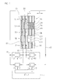
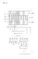
- a position measuring device comprises a code carrier 1, which can be scanned by a scanning device with a plurality of detectors D1, D2, D3, D4.
- the code carrier 1 is displaceable relative to the scanning device in the measuring direction X.
- the position measuring device is designed so that a reliable absolute position measurement is ensured.
- This coding of the code carrier 1 is a pseudo-random code, which consists of a sequence of code elements C1, C2, C3, C4, which are arranged consecutively in the measuring direction X.
- Each code element C1, C2, C3, C4 again consists of two subregions C1A, C1B; C2A, C2B; C3A, C3B; C4A, C4B, which are complementary to each other.
- Complementary means that they have inverse properties, ie in the optical scanning principle in transmitted light scanning transparent and non-transparent or reflective or non-reflective in incident light scanning.
- the first sections C1A, C2A, C3A, C4A of the code elements C1, C2, C3, C4 in this embodiment are in a first code track SA and the second sections C1B, C2B, C3B, C4B of the code elements C1, C2, C3, C4 in one arranged second code track SB, which runs parallel to the first code track SA.
- the code carrier 1 has, in addition to the code tracks SA, SB, a periodic incremental graduation. This incremental graduation is subdivided into incremental partial tracks S1, S2, S3 and arranged on both sides of the first code track SA and on both sides of the second code track SB.
- the incremental partial tracks S1, S2, S3 run parallel to the two code tracks SA, SB in the measuring direction X.
- the detectors D1, D2, D3, D4 comprise at least a first detector D1 for the common scanning of the respective first subarea C1A, C2A, C3A, C4A of a code element C1, C2, C3, C4 and the incremental graduation.
- the first detector D1 of the first code track SA and the incremental partial tracks S1, S2 extending on both sides are assigned to them and scanned in the position measurement.
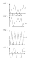
- This first detector D1 thereby supplies a first sampling signal A1 whose position-dependent course along the code elements C1, C2, C3, C4 in FIG FIG. 2 is shown schematically.
- the plurality of detectors D1, D2, D3, D4 furthermore comprise at least one second detector D2 for jointly scanning the second sub-area C1B, C2B, C3B, C4B in each case one of the code elements C1, C2, C3, C4 and the incremental graduation.
- the second detector D2 is associated with the second code track SB and the incremental partial tracks S2, S3 running on both sides and scans them during the position measurement.
- This second detector D2 thereby supplies a second scanning signal A2 whose position-dependent course as a function of the position along the code elements C1, C2, C3, C4 in FIG FIG. 3 is shown schematically.
- the detectors D1, D2 respectively detect the instantaneous light distribution and generate a position-dependent analog scanning signal A1, A2 proportional to the detected light intensity as a function of the light intensity.
- the actual course of the scanning signals A1, A2 can from the in the FIGS. 2 and 3 deviate course shown, in particular, a smooth course will result without corners.
- the in FIG. 4 Periodic incremental signal I1 shown in practice give a sinusoidal waveform.
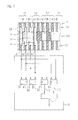
- the first scanning signal A1 and the second scanning signal A2 are fed to an evaluation unit 3.
- the evaluation unit 3 is designed to compare the first scanning signal A1 with the second scanning signal A2.
- the comparison result defines the code information B1 of the code element C1 in the illustrated sampling position.
- the comparison may include quoting or forming a difference.
- the difference formation is particularly easy to implement.
- the components resulting from the scanning of the incremental pitch cancel out completely.
- the proportions which result from the scanning of the code element C1 add up.
- the degree of modulation of the signal which defines the code information B1 is thereby doubled.
- the course of the signal which defines the code information B is dependent on the position along the code elements C1, C2, C3, C4 in FIG FIG.
- a first comparator 3.1 and for comparing the two scanning signals A3, A4, a second comparator 3.2 is provided in the illustrated example.
- the two comparators can be designed to generate the respective scanning signals A1, A2 and A3, A4 as analog signals or alternatively as digital signals to compare.
- the evaluation unit 3 is further supplied with the first scanning signal A1 and the second scanning signal A2 in order to form a periodic incremental signal I1 by combining these scanning signals A1 and A2.
- This combination is preferably a simple addition.
- the portions of the signals from the scanning of the code tracks SA, SB cancel and the proportions of the signals from the sampling of the incremental graduation, so the incremental partial tracks S1, S2, S3 are added.
- the position-dependent profile of the periodic incremental signal I1 is in FIG. 4 shown schematically.
- the scanning device comprises further detectors, which are each an integer multiple of the length of a portion C1A, C1B, C2A, C2B, C3A, C3B, C4A, C4B of a first and second detectors D1, D2 Code element C1, C2, C3, C4 are arranged.
- a first and second detectors D1, D2 Code element C1, C2, C3, C4 are arranged.
- FIG. 1 another first detector D3 and another second detector D4 shown.
- the processing of the scanning signals A3, A4 obtained thereby takes place in accordance with the scanning signals A1, A2, in that the second code information B2 for the second code element C2 is obtained by subtraction and a further periodic incremental signal I2 is obtained by addition.
- the two incremental signals I1, I2 are in phase, so that they can be added up to form a common periodic incremental signal I, whereby the degree of modulation of the provided at the evaluation unit 3 periodic incremental signal I is increased.
- a first module 3.3 and for combining the two scanning signals A3, A4, a second module 3.4 is provided in the example shown.
- the two components can be designed to generate the respective scanning signals A1, A2 and A3, A4 as analog signals or alternatively to combine as digital signals together, in particular to add.
- the period length T of the periodic incremental graduation corresponds to the length (in measuring direction X) of a subregion C1A, C1B, C2A, C2B, C3A, C3B, C4A, C4B.
- the incremental signal I1 with a signal period corresponding to the length T is available.
- the periodic incremental signal I or I1 or I2 can be used to subdivide even more finely the distance absolutely absolutely spatially resolved by the code information B in steps corresponding to the length T.
- the incremental signal I or I1 or I2 is interpolated in a known manner.
- a further incremental track can additionally be arranged parallel to the already existing tracks, the graduation period of which is then smaller than the period length T.
- the periodic incremental signals I1, I1, I can also be used to optimize the sampling of the code elements C1, C2, C3, C4. This can be done in a known manner by arranging several detectors within the length of a code element C1, C2, C3, C4 and the position information from the incremental signal (interpolation value within one division period T) is used to select one of the plurality of detectors for forming the code information B. The detector is then selected, which scans the code element as centrally as possible in order to obtain a unique code information. This is expressly on the EP 1 821 073 A2 directed.
- the geometrical arrangement of the code elements C1, C2, C3, C4 and incremental divisions required for the invention is advantageously chosen such that, on the one hand, a space-saving arrangement and, on the other hand, a large tolerance in the scanning can be achieved.
- the space-saving arrangement is characterized by the common scanning of the first code track SA and the incremental division - here in the form of the incremental partial tracks S1, S2 - by means of the first detector D1 and by the common scanning of the second code track SB and the incremental graduation - here in the form of the incremental Partial tracks S2, S3 - ensured by means of the second detector D2.
- a large tolerance is preferably achieved by assigning the first detector D1 to form the first scanning signal A1 of the first code track SA and the incremental partial tracks S1, S2 running on both sides, and that the second detector D2 to form the second scanning signal A2 of the second code track SB and on both sides extending incremental partial tracks S2, S3 is assigned.
- the first detector D1 By means of these incremental partial tracks S1, S2, S3, which are arranged symmetrically to the code tracks SA, SB, it is now possible for the first detector D1 to have an extension perpendicular to the measuring direction X, such that it extends the incremental partial tracks S1 running on both sides of the first code track SA , S2 each only partially overlapped, and that the second detector D2 perpendicular to the measuring direction X has an extension that he On both sides of the second code track SB extending incremental partial tracks S2, S3 only partially overlapped.
- the non-overlapping region serves as a tolerance range for the position of the scanning device relative to the code carrier 1 perpendicular to the measuring direction X. Within this tolerance range, the scanning device can change its position relative to the code carrier 1 perpendicular to the measuring direction X, without causing the first scanning signal A1 as well as the second Scanning signal A2 are modulated.
- the symmetry condition required to achieve the large tolerances is achieved here by the first code track being in first code partial tracks SA1, SA2 extending parallel to one another and the second code track being formed into second code running parallel to one another Partial tracks SB1, SB2 are arranged, on both sides parallel to one of the incremental partial tracks S4 in each case run the first code sub-tracks SA1, SA2 and both sides parallel to one of the incremental sub-tracks S5, the second code sub-tracks SB1, SB2 run.
- the subregions C4A and C4B of the code subtracks SA1, SA2, SB1, SB2 provided with reference numerals.
- the first detector D1 has an extent transverse to the measuring direction X, that it only partially overlaps the first code partial tracks SA1, SA2 arranged on both sides of the first incremental partial track S4, and the second detector D2 has an extension transverse to the measuring direction X. in that it only partially overlaps the second code subtracks SB1, SB2 arranged on both sides of the second incremental subtrack S5.
- the same scanning signals A1 to A4 are generated as in the first embodiment, so that the evaluation in the manner described above using the evaluation unit 3 and the code information B1 and B2 for the two code elements C1 and C2 and the periodic incremental signal I are formed ,
- the first partial areas C1A, C2A, C3A, C4A and the second partial areas C1B, C2B, C3B, C4B of each of the code elements C1, C2, C3, C4 are arranged successively in the measuring direction X in a common code track SAB.
- the first detector D1 and the second detector D2 are now arranged at a distance corresponding to the length of one of the subareas C1A, C1B, C2A, C2B, C3A, C3B, C4A, C4B for generating the code information B1 and the periodic incremental signal I1.
- the first scanning signal A1 is again generated by means of the first detector D1 by common scanning.
- the second scanning signal A2 is again generated by means of the second detector D2 by common sampling.
- the incremental graduation in incremental partial tracks S6, S7 arranged on both sides parallel to the common code track SAB is according to the FIG. 7 .
- the first detector D1 and the second detector D2 preferably each have an extension perpendicular to the measuring direction X, such that they only partially overlap the incremental partial tracks S6, S7 running on both sides of the common code track SAB.
- the same scanning signals A1 to A4 are generated as in the first exemplary embodiment, so that the evaluation in the manner described above takes place on the basis of the evaluation unit 3 and the code information B1 and B2 are formed for the two code elements C1 and C2 and the periodic incremental signal I.
- the first detector D1 and the second detector D2 have an extension perpendicular to the measuring direction X, that they only partially overlap the first code sub-track SAB1 and the second code sub-track SAB2.
- the same scanning signals A1 to A4 are generated as in the first embodiment, so that the evaluation in the manner described above using the evaluation unit 3 and the code information B1 and B2 for the two code elements C1 and C2 and the periodic incremental signal I are formed.
- the distributions of the tracks in partial tracks to achieve a high tolerance specified in the exemplary embodiments are particularly advantageous, but not mandatory for the invention. If, in fact, the scanning device is guided well relative to the code carrier in the position measurement in measuring direction X, transverse movements of the scanning unit are negligible.
- the periodic incremental graduation has edges running 90 ° to the measuring direction X. These edges can be shaped differently for harmonic filtering in a known manner. As an example, on the DE 10 2004 041 950 A1 directed. In this case, the edges of the incremental graduation with respect to the measuring direction X run at an angle other than 90 °.
Abstract
Description
- Die Erfindung betrifft eine Positionsmesseinrichtung zur Bestimmung der absoluten Position.
- Auf vielen Gebieten werden vermehrt absolute Positionsmesseinrichtungen eingesetzt, bei denen die absolute Positionsinformation aus einer Codespur mit in Messrichtung hintereinander angeordneten Codeelementen abgeleitet wird. Die Codeelemente sind dabei in pseudozufälliger Verteilung vorgesehen, so dass eine bestimmte Anzahl von aufeinander folgenden Codeelementen jeweils ein Bitmuster bildet. Bei der Verschiebung der Abtasteinrichtung gegenüber der Codespur um ein einziges Codeelement wird bereits ein neues Bitmuster gebildet und über den gesamten absolut zu erfassenden Messbereich steht eine Folge von unterschiedlichen Bitmustern zur Verfügung.
- Ein derartiger sequentieller Code wird als Kettencode oder als Pseudo-Random-Code (PRC) bezeichnet.
- Eine absolute Positionsmesseinrichtung, von der diese Erfindung ausgeht, ist in der
EP 2 416 126 A1 beschrieben. Gemäß dem dort inFigur 3 offenbarten Ausführungsbeispiel weist die Positionsmesseinrichtung einen Codeträger mit einer Codespur auf, die aus einer Folge von in Messrichtung hintereinander angeordneten Codeelementen besteht. In einer parallel zur Codespur angeordneten Spur ist eine periodische Inkrementalteilung angeordnet. Detektoren einer Abtasteinrichtung tasten jeweils gemeinsam die Codespur und die Inkrementalteilung ab und erzeugen somit ein gemeinsames Abtastsignal aus den beiden Spuren. Dieses Abtastsignal wird einer Auswerteeinheit zugeführt, die daraus eine Codeinformation und ein periodisches Inkrementalsignal bildet. - Nachteilig dabei ist der relativ geringe Modulationsgrad der Abtastsignale und die relativ aufwendige Auswertung.
- Der Erfindung liegt die Aufgabe zugrunde, eine absolute Positionsmesseinrichtung zu schaffen, mit der auf einfache Weise eine korrekte absolute Position mit hoher Zuverlässigkeit sowie zumindest ein periodisches Inkrementalsignal erzeugbar ist.
- Diese Aufgabe wird durch die Merkmale des Anspruches 1 gelöst. Demnach umfasst die Positionsmesseinrichtung
- einen Codeträger mit
- einer Folge von Codeelementen, wobei jedes Codeelement aus einem ersten Teilbereich und einem zweiten Teilbereich besteht, die zueinander komplementäre Eigenschaften aufweisen, und
- einer periodischen Inkrementalteilung;
- eine Abtasteinrichtung mit mehreren Detektoren,
- wobei ein erster Detektor zur gemeinsamen Abtastung des ersten Teilbereichs eines der Codeelemente sowie der Inkrementalteilung ausgebildet ist und dadurch ein erstes Abtastsignal erzeugbar ist und
- wobei ein zweiter Detektor zur gemeinsamen Abtastung des zweiten Teilbereichs des einen Codeelementes sowie der Inkrementalteilung ausgebildet ist und dadurch ein zweites Abtastsignal erzeugbar ist;
- eine Auswerteeinheit, welcher das erste Abtastsignal und das zweite Abtastsignal zugeführt sind und die dazu ausgebildet ist, daraus eine Codeinformation für das Codeelement sowie ein periodisches Inkrementalsignal zu bilden.
- Die Ausgestaltung der Codeelemente wird in bekannter Weise abhängig vom Abtastprinzip gewählt. So können die Codeelemente optisch, magnetisch, kapazitiv oder induktiv abtastbar ausgestaltet sein. Entsprechend der Ausgestaltung der Codeelemente werden auch die Detektoren gewählt.
- Komplementäre Eigenschaften bedeutet dabei, dass die Teilbereiche der Codeelemente inverse Eigenschaften besitzen, so dass diese bei der Abtastung Abtastsignale bilden, die invers zueinander verlaufen. Die damit erzeugten Abtastsignale innerhalb eines Codeelementes werden daher auch Taktsignal und Gegentaktsignal bezeichnet.
- Zur besonders vorteilhaften optischen Abtastung weisen die zwei Teilbereiche eines Codeelementes jeweils zueinander komplementäre optische Eigenschaften auf, bei Durchlicht-Abtastung somit transparente und nicht transparente bzw. bei Auflicht-Abtastung reflektierende bzw. nicht reflektierende Teilbereiche.
- Zur Bildung der Codeinformation und des periodischen Inkrementalsignal werden das erste Abtastsignal und das zweite Abtastsignal der Auswerteeinheit zugeführt. Die Abtastsignale können von der Auswerteeinheit als analoge Signale in Form von Strömen oder Spannungen verarbeitet werden. Alternativ können die Abtastsignale von der Auswerteeinheit als digitale Werte in Form von mehrstelligen Wörtern (n Bits, mit n>1) verarbeitet werden, wozu die von den Detektoren erzeugten analogen Abtastsignale vor der Verarbeitung A/D-gewandelt werden.
- Das periodische Inkrementalsignal wird vorzugsweise von der Auswerteeinheit durch Addition des ersten Abtastsignals und des zweiten
- Abtastsignals gebildet. Dadurch wird ein periodisches Inkrementalsignal gewonnen, das innerhalb einer Periode gut interpolationsfähig ist, wodurch genaue absolute Zwischenwerte innerhalb einer Periode und somit innerhalb der Länge eines Codeelementes gebildet werden können.
- Die Abfolge der zueinander komplementär ausgebildeten Teilbereiche eines Codeelementes bestimmt die Codeinformation des jeweiligen Codeelementes. Einer ersten Abfolge wird ein erster binärer Wert und einer zweiten Abfolge ein zweiter binärer Wert zugeordnet.
- Die Codeinformation wird vorzugsweise durch Vergleich des ersten Abtastsignals mit dem zweiten Abtastsignal gebildet, insbesondere durch Bilden der Differenz, in besonders vorteilhafter Weise durch Subtraktion des zweiten Abtastsignals vom ersten Abtastsignal. Erfolgt in der Auswerteeinheit eine analoge Signalverarbeitung, sind die miteinander zu vergleichenden Abtastsignale Ströme oder Spannungen, die mittels eines Komparators verglichen werden. Erfolgt in der Auswerteeinheit eine digitale Signalverarbeitung, sind die miteinander zu vergleichenden Abtastsignale digitale Werte, die mittels eines Komparators verglichen werden, wobei in diesem Fall am Ausgang des Komparators die Codeinformation direkt als Digitalwert (ein Bit) zur Verfügung steht.
- Die zwei zueinander komplementären Teilbereiche der Codeelemente können bei der Erfindung in separaten zueinander parallel verlaufenden Codespuren angeordnet sein oder alternativ in einer gemeinsamen Codespur, indem die ersten Teilbereiche der Codeelemente und die zweiten Teilbereiche der Codeelemente jeweils in Messrichtung aufeinanderfolgend angeordnet sind.
- Bei beiden Anordnungen ist es nun vorteilhaft, wenn die Inkrementalteilung und / oder die Codespur in mehrere gleiche parallel und fluchtend zueinander angeordnete Teilspuren aufgeteilt ist bzw. sind. Dadurch ist es möglich, senkrecht zur Messrichtung symmetrische Spuranordnungen zu erhalten. Wenn bei diesen symmetrischen Spuranordnungen die Ausdehnung der Detektoren senkrecht zur Messrichtung kleiner gewählt wird wie die Spuranordnung, entsteht für die Abtasteinrichtung in einer Richtung senkrecht zur Messrichtung, also in Strichrichtung der Inkrementalteilung, ein relativ großer Toleranzbereich in dem eine Relativbewegung gegenüber dem Codeträger möglich ist, ohne dass eine Modulation der Abtastsignale resultiert.
- Weitere vorteilhafte Ausgestaltungen der Erfindung sind in den abhängigen Ansprüchen angegeben.
- Die Erfindung wird anhand der Zeichnungen näher erläutert, dabei zeigen:
- Figur 1
- eine erste Positionsmesseinrichtung in schematischer Darstellung;
- Figur 2
- ein erstes Abtastsignal der Positionsmesseinrichtung gemäß
Figur 1 ; - Figur 3
- ein zweites Abtastsignal der Positionsmesseinrichtung gemäß
Figur 1 ; - Figur 4
- ein aus den Abtastsignalen gewonnenes periodisches Inkrementalsignal;
- Figur 5
- eine aus den Abtastsignalen gewonnene Codeinformation;
- Figur 6
- eine zweite Positionsmesseinrichtung;
- Figur 7
- eine dritte Positionsmesseinrichtung, und
- Figur 8
- eine vierte Positionsmesseinrichtung.
- Die erfindungsgemäße absolute Positionsmesseinrichtung kann zur Messung von linearen oder rotatorischen Bewegungen eingesetzt werden, wobei ein Codeträger dabei an einem der zu messenden Objekte und eine Abtasteinrichtung am anderen der zu messenden Objekte angebracht ist. Die zu messenden Objekte können dabei der Tisch und der Schlitten einer Werkzeugmaschine, einer Koordinatenmessmaschine oder der Rotor und der Stator eines Elektromotors sein.
- Anhand der
Figuren 1 bis 5 wird ein erstes Ausführungsbeispiel einer Positionsmesseinrichtung näher erläutert. Sie umfasst einen Codeträger 1, der von einer Abtasteinrichtung mit mehreren Detektoren D1, D2, D3, D4 abtastbar ist. Der Codeträger 1 ist relativ zur Abtasteinrichtung in Messrichtung X verschiebbar. - Die Positionsmesseinrichtung ist dazu ausgelegt, dass eine zuverlässige absolute Positionsmessung gewährleistet ist.
- Eine zuverlässige Positionsmessung wird durch die Verwendung einer speziellen Codierung erreicht. Diese Codierung des Codeträgers 1 ist ein Pseudo-Random-Code, der aus einer Folge von Codeelementen C1, C2, C3, C4 besteht, die in Messrichtung X aufeinanderfolgend angeordnet sind. Jedes Codeelement C1, C2, C3, C4 besteht wiederum aus zwei Teilbereichen C1A, C1B; C2A, C2B; C3A, C3B; C4A, C4B, die zueinander komplementär ausgebildet sind. Komplementär bedeutet dabei, dass sie inverse Eigenschaften besitzen, also beim optischen Abtastprinzip bei Durchlicht-Abtastung transparent und nicht transparent bzw. bei Auflicht-Abtastung reflektierend bzw. nicht reflektierend sind. Die ersten Teilbereiche C1A, C2A, C3A, C4A der Codeelemente C1, C2, C3, C4 sind in diesem Ausführungsbeispiel in einer ersten Codespur SA und die zweiten Teilbereiche C1B, C2B, C3B, C4B der Codeelemente C1, C2, C3, C4 in einer zweiten Codespur SB angeordnet, die parallel zur ersten Codespur SA verläuft.
- Im dargestellten Beispiel gemäß
Figur 1 wird davon ausgegangen, dass die Abfolge der Teilbereiche C1A, C2A, C3A, C4A der ersten Codespur SA zu den Teilbereichen C1B, C2B, C3B, C4B der zweiten Codespur SB jeweils eines Codeelementes C1 bis C4 dunkel -> hell die Codeinformation B in Form eines Bits=0 und die Abfolge hell -> dunkel die Codeinformation B in Form eines Bits=1 definiert. Somit definiert die Folge von Codeelementen C1 bis C4 des inFigur 1 dargestellten Codes die Codeinformation 0100. - Der Codeträger 1 weist neben den Codespuren SA, SB eine periodische Inkrementalteilung auf. Diese Inkrementalteilung ist in Inkremental-Teilspuren S1, S2, S3 aufgeteilt und beidseitig zur ersten Codespur SA sowie beidseitig zur zweiten Codespur SB angeordnet. Die Inkremental-Teilspuren S1, S2, S3 verlaufen parallel zu den beiden Codespuren SA, SB in Messrichtung X.
- Die Detektoren D1, D2, D3, D4 umfassen zumindest einen ersten Detektor D1 zur gemeinsamen Abtastung jeweils des ersten Teilbereichs C1A, C2A, C3A, C4A eines Codeelementes C1, C2, C3, C4 sowie der Inkrementalteilung. Hierzu ist der erste Detektor D1 der ersten Codespur SA sowie den beidseits dazu verlaufenden Inkremental-Teilspuren S1, S2 zugeordnet und tastet diese bei der Positionsmessung ab. Dieser erste Detektor D1 liefert dadurch ein erstes Abtastsignal A1, dessen positionsabhängiger Verlauf entlang der Codeelemente C1, C2, C3, C4 in
Figur 2 schematisch dargestellt ist. - Die mehreren Detektoren D1, D2, D3, D4 umfassen weiterhin zumindest einen zweiten Detektor D2 zur gemeinsamen Abtastung des zweiten Teilbereichs C1B, C2B, C3B, C4B jeweils eines der Codeelemente C1, C2, C3, C4 sowie der Inkrementalteilung. Hierzu ist der zweite Detektor D2 der zweiten Codespur SB sowie den beidseits dazu verlaufenden Inkremental-Teilspuren S2, S3 zugeordnet und tastet diese bei der Positionsmessung ab. Dieser zweite Detektor D2 liefert dadurch ein zweites Abtastsignal A2, dessen positionsabhängiger Verlauf in Abhängigkeit der Position entlang der Codeelemente C1, C2, C3, C4 in
Figur 3 schematisch dargestellt ist. - Die Detektoren D1, D2 erfassen bei der Positionsmessung jeweils die momentane Lichtverteilung und erzeugen in Abhängigkeit der Lichtintensität ein positionsabhängiges analoges Abtastsignal A1, A2 proportional zur erfassten Lichtintensität. Der tatsächliche Verlauf der Abtastsignale A1, A2 kann von dem in den
Figuren 2 und 3 dargestellten Verlauf abweichen, insbesondere wird sich ein fließender Verlauf ohne Ecken ergeben. Daraus resultierend wird sich für das inFigur 4 dargestellte periodische Inkrementalsignal I1 in der Praxis ein sinus-förmiger Verlauf ergeben. - Das erste Abtastsignal A1 und das zweite Abtastsignal A2 werden einer Auswerteeinheit 3 zugeführt. Die Auswerteeinheit 3 ist dazu ausgelegt das erste Abtastsignal A1 mit dem zweiten Abtastsignal A2 zu vergleichen. Das Vergleichsergebnis definiert in der dargestellten Abtastposition die Codeeinformation B1 des Codeelementes C1. Der Vergleich kann eine Quotientenbildung oder das Bilden einer Differenz umfassen. Besonders einfach ist die Differenzbildung realisierbar. Durch Bilden der Differenz zwischen dem ersten Abtastsignal A1 und dem zweiten Abtastsignal A2 heben sich die Anteile, welche aus der Abtastung der Inkrementalteilung resultiert, vollständig auf. Weiterhin addieren sich die Anteile, welche aus der Abtastung des Codeelementes C1 resultieren. Der Modulationsgrad des Signals, welches die Codeinformation B1 definiert, wird dadurch verdoppelt. Der Verlauf des Signales, welches die Codeinformation B definiert, ist in Abhängigkeit der Position entlang der Codeelemente C1, C2, C3, C4 in
Figur 5 schematisch dargestellt. Die Erhöhung des Modulationsgrades resultiert daraus, dass die beiden Teilbereiche C1A und C1B des Codeelementes C1 komplementär zueinander ausgebildet sind, so dass damit auch die Intensitäten der Abtastsignale der ersten Codespur SA und der zweiten Codespur SB allein betrachtet invers zueinander sind. - Zum Vergleich der beiden Abtastsignale A1, A2 ist im dargestellten Beispiel ein erster Komparator 3.1 und zum Vergleich der beiden Abtastsignale A3, A4 ein zweiter Komparator 3.2 vorgesehen. Die beiden Komparatoren können dazu ausgebildet sein, die jeweiligen Abtastsignale A1, A2 sowie A3, A4 als Analogsignale oder alternativ als Digitalsignale miteinander zu vergleichen.
- Der Auswerteeinheit 3 wird das erste Abtastsignal A1 und das zweite Abtastsignal A2 desweitern zugeführt, um daraus durch Kombination dieser Abtastsignale A1 und A2 ein periodisches Inkrementalsignal I1 zu bilden. Diese Kombination ist vorzugsweise eine einfache Addition. Bei dieser Addition heben sich die Anteile der Signale aus der Abtastung der Codespuren SA, SB auf und die Anteile der Signale aus der Abtastung der Inkrementalteilung, also der Inkremental-Teilspuren S1, S2, S3 werden addiert. Der positionsabhängige Verlauf des periodischen Inkrementalsignals I1 ist in
Figur 4 schematisch dargestellt. - Zur Gewinnung eines mehrstelligen Codewortes an einer Momentanposition umfasst die Abtasteinrichtung weitere Detektoren, die gegenüber den ersten und den zweiten Detektoren D1, D2 jeweils um ein ganzzahlig Vielfaches der Länge eines Teilbereiches C1A, C1B, C2A, C2B, C3A, C3B, C4A, C4B eines Codeelementes C1, C2, C3, C4 angeordnet sind. Im Beispiel ist in
Figur 1 ein weiterer erster Detektor D3 und ein weiterer zweiter Detektor D4 dargestellt. Die Verarbeitung der dadurch gewonnenen Abtastsignale A3, A4 erfolgt entsprechend der Abtastsignale A1, A2, indem durch Differenzbildung die zweite Codeinformation B2 für das zweite Codeelement C2 gewonnen wird und durch Addition ein weiteres periodisches Inkrementalsignal I2 gewonnen wird. Die beiden Inkrementalsignale I1, I2 sind phasengleich, so dass diese zu einem gemeinsamen periodischen Inkrementalsignal I aufaddiert werden können, wodurch der Modulationsgrad des an der Auswerteeinheit 3 zur Verfügung gestellten periodischen Inkrementalsignals I erhöht wird. - Zur Kombination der beiden Abtastsignale A1, A2 ist im dargestellten Beispiel ein erster Baustein 3.3 und zur Kombination der beiden Abtastsignale A3, A4 ein zweiter Baustein 3.4 vorgesehen. Die beiden Bausteine können dazu ausgebildet sein, die jeweiligen Abtastsignale A1, A2 sowie A3, A4 als Analogsignale oder alternativ als Digitalsignale miteinander zu kombinieren, insbesondere zu addieren.
- Besonders vorteilhaft ist es, wenn die Periodenlänge T der periodischen Inkrementalteilung der Länge (in Messrichtung X) eines Teilbereiches C1A, C1B, C2A, C2B, C3A, C3B, C4A, C4B entspricht. Dadurch steht innerhalb einer absoluten Codeinformation B das Inkrementalsignal I1 mit einer Signalperiode entsprechend der Länge T zur Verfügung.
- In nicht gezeigter Weise ist es möglich, zusätzliche Detektoren innerhalb der Länge T vorzusehen. Mit diesen Detektoren können dann zu den oben beschriebenen Abtastsignalen A1, A2 phasenverschobene Abtastsignale erzeugt werden, und daraus wiederum zu der vorhandenen Codeinformationen B1 phasenverschobene Codeinformationen sowie zu dem Inkrementalsignal I1 phasenverschobene Inkrementalsignale. Zur Erzeugung von vier jeweils um 90° gegeneinander phasenverschobener periodischer Inkrementalsignale sind vier Detektoren D1 und vier Detektoren D2 innerhalb einer Periode T anzuordnen.
- Das periodische Inkrementalsignal I oder I1 bzw. I2 kann dazu verwendet werden, die durch die Codeinformation B in Schritten entsprechend der Länge T absolut ortsaufgelöste Wegstrecke noch feiner absolut zu unterteilen. Hierzu wird das Inkrementalsignal I oder I1 bzw. I2 in bekannter Weise interpoliert.
- Wird eine noch weiter unterteilte Positionsmessung gefordert, kann parallel zu den bereits vorhandenen Spuren zusätzlich eine weitere Inkrementalspur angeordnet werden, dessen Teilungsperiode dann kleiner ist als die Periodenlänge T.
- Die periodischen Inkrementalsignale I1, I1, I können auch dazu verwendet werden, die Abtastung der Codeelemente C1, C2, C3, C4 zu optimieren. Dies kann in bekannter Weise dadurch erfolgen, dass innerhalb der Länge eines Codeelementes C1, C2, C3, C4 mehrere Detektoren angeordnet werden und die Positionsinformation aus dem Inkrementalsignal (Interpolationswert innerhalb einer Teilungsperiode T) dazu verwendet wird einen dieser mehreren Detektoren zur Bildung der Codeinformation B auszuwählen. Ausgewählt wird dann der Detektor, der das Codeelement möglichst mittig abtastet, um eine eindeutige Codeinformation zu erhalten. Hierzu wird ausdrücklich auf die
EP 1 821 073 A2 verwiesen. - Die geometrische Anordnung der für die Erfindung erforderlichen Codeelemente C1, C2, C3, C4 und Inkrementalteilungen ist in vorteilhafter Weise derart gewählt, dass einerseits eine platzsparende Anordnung und andererseits aber auch eine große Toleranz bei der Abtastung erreichbar sind.
- Die platzsparende Anordnung ist durch die gemeinsame Abtastung der ersten Codespur SA und der Inkrementalteilung - hier in Form der Inkremental-Teilspuren S1, S2 - mittels des ersten Detektors D1 sowie durch die gemeinsame Abtastung der zweiten Codespur SB und der Inkrementalteilung - hier in Form der Inkremental-Teilspuren S2, S3 - mittels des zweiten Detektors D2 gewährleistet. Damit wird ermöglicht, die Codespuren SA, SB und die Inkremental-Teilspuren S1, S2, S3 direkt nebeneinander (senkrecht zur Messrichtung X betrachtet) anzuordnen.
- Eine große Toleranz wird vorzugsweise dadurch erreicht, indem der erste Detektor D1 zur Bildung des ersten Abtastsignals A1 der ersten Codespur SA sowie den beidseits dazu verlaufenden Inkremental-Teilspuren S1, S2 zugeordnet ist, und dass der zweite Detektor D2 zur Bildung des zweiten Abtastsignals A2 der zweiten Codespur SB sowie den beidseits dazu verlaufenden Inkremental-Teilspuren S2, S3 zugeordnet ist. Durch diese jeweils symmetrisch zu den Codespuren SA, SB angeordneten Inkremental-Teilspuren S1, S2, S3 ist es nun möglich, dass der erste Detektor D1 senkrecht zur Messrichtung X eine Ausdehnung aufweist, dass er die beidseits zur ersten Codespur SA verlaufenden Inkremental-Teilspuren S1, S2 jeweils nur teilweise überlappt, und dass der zweite Detektor D2 senkrecht zur Messrichtung X eine Ausdehnung aufweist, dass er die beidseits zur zweiten Codespur SB verlaufenden Inkremental-Teilspuren S2, S3 jeweils nur teilweise überlappt. Der nicht überlappende Bereich dient als Toleranzbereich für die Lage der Abtasteinrichtung gegenüber dem Codeträger 1 senkrecht zur Messrichtung X. Innerhalb dieses Toleranzbereiches kann die Abtasteinrichtung ihre Lage relativ zum Codeträger 1 senkrecht zur Messrichtung X verändern, ohne dass dabei das erste Abtastsignal A1 sowie auch das zweite Abtastsignal A2 moduliert werden.
- Anhand der
Figur 6 wird ein zweites Ausführungsbeispiel erläutert. Die zueinander komplementären Teilbereiche C1A, C1B; C2A, C2B; C3A, C3B; C4A, C4B der Codeelemente C1, C2, C3, C4 sind wiederum in separaten Codespuren angeordnet. Im Unterschied zu dem vorhergehenden Ausführungsbeispiel ist die zum Erreichen der großen Toleranzen (senkrecht zur Messrichtung X) geforderte Symmetriebedingung hier dadurch erreicht, dass die erste Codespur in parallel zueinander verlaufende erste Code-Teilspuren SA1, SA2 sowie die zweite Codespur in zweite parallel zueinander verlaufende Code-Teilspuren SB1, SB2 angeordnet sind, wobei beidseits parallel zu einer der Inkremental-Teilspuren S4 jeweils die ersten Code-Teilspuren SA1, SA2 verlaufen und beidseits parallel zu einer der Inkremental-Teilspuren S5 die zweiten Code-Teilspuren SB1, SB2 verlaufen. Aus Gründen der Übersichtlichkeit sind in derFigur 6 nur die Teilbereiche C4A und C4B der Code- Teilspuren SA1, SA2, SB1, SB2 mit Bezugszeichen versehen. - Zur Abtastung weist der erste Detektor D1 quer zur Messrichtung X eine Ausdehnung auf, dass er die beidseits der ersten Inkremental-Teilspur S4 angeordneten ersten Code-Teilspuren SA1, SA2 jeweils nur teilweise überlappt, und weist der zweite Detektor D2 quer zur Messrichtung X eine Ausdehnung auf, dass er die beidseits der zweiten Inkremental-Teilspur S5 angeordneten zweiten Code-Teilspuren SB1, SB2 jeweils nur teilweise überlappt.
- Bei diesem zweiten Ausführungsbeispiel werden die gleichen Abtastsignale A1 bis A4 erzeugt wie beim ersten Ausführungsbeispiel, so dass die Auswertung in oben beschriebener Weise anhand der Auswerteeinheit 3 erfolgt und die Codeinformationen B1 und B2 für die beiden Codeelemente C1 und C2 sowie das periodische Inkrementalsignal I gebildet werden.
- Anhand der
Figuren 7 und8 werden ein drittes und ein viertes Ausführungsbeispiel der Erfindung erläutert. Dabei sind die ersten Teilbereiche C1A, C2A, C3A, C4A und die zweiten Teilbereiche C1B, C2B, C3B, C4B jedes der Codeelemente C1, C2, C3, C4 jeweils in Messrichtung X aufeinanderfolgend in einer gemeinsamen Codespur SAB angeordnet. Der erste Detektor D1 und der zweite Detektor D2 sind zur Erzeugung der Codeinformation B1 sowie des periodischen Inkrementalsignals I1 nun in einem Abstand entsprechend der Länge eines der Teilbereiche C1A, C1B, C2A, C2B, C3A, C3B, C4A, C4B angeordnet. Aus dem ersten Teilbereich C1A sowie der zugeordneten Inkrementalteilung wird mittels des ersten Detektors D1 durch gemeinsame Abtastung wiederum das erste Abtastsignal A1 erzeugt. Aus dem zweiten Teilbereich C1B sowie der zugeordneten Inkrementalteilung wird mittels des zweiten Detektors D2 durch gemeinsame Abtastung wiederum das zweite Abtastsignal A2 erzeugt. - Zum Erreichen einer großen Toleranz ist gemäß der
Figur 7 die Inkrementalteilung in Inkremental-Teilspuren S6, S7 beidseits parallel zur gemeinsamen Codespur SAB angeordnet. Der erste Detektor D1 und der zweite Detektor D2 weisen vorzugsweise senkrecht zur Messrichtung X jeweils eine Ausdehnung auf, dass er die beidseits zur gemeinsamen Codespur SAB verlaufenden Inkremental-Teilspuren S6, S7 jeweils nur teilweise überlappt. - Dadurch werden die gleichen Abtastsignale A1 bis A4 erzeugt wie beim ersten Ausführungsbeispiel, so dass die Auswertung in oben beschriebener Weise anhand der Auswerteeinheit 3 erfolgt und die Codeinformationen B1 und B2 für die beiden Codeelemente C1 und C2 sowie das periodische Inkrementalsignal I gebildet werden.
- Zum Erreichen einer großen Toleranz ist gemäß der
Figur 8 die gemeinsame Codespur in Code-Teilspuren SAB1, SAB2 angeordnet, die beidseits parallel zu einer Inkrementalspur S8 verlaufen. - Der erste Detektor D1 und der zweite Detektor D2 weisen senkrecht zur Messrichtung X eine Ausdehnung auf, dass diese die erste Code-Teilspur SAB1 sowie die zweite Code-Teilspur SAB2 jeweils nur teilweise überlappen.
- Dadurch werden die gleichen Abtastsignale A1 bis A4 erzeugt wie beim ersten Ausführungsbeispiel, so dass die Auswertung in oben beschriebener Weise anhand der Auswerteeinheit 3 erfolgt und die Codeinformationen B1 und B2 für die beiden Codeelemente C1 und C2 sowie das periodische Inkrementalsignal I gebildet werden.
- Die in den Ausführungsbeispielen angegebenen Aufteilungen der Spuren in Teilspuren zum Erreichen einer großen Toleranz sind besonders vorteilhaft, aber für die Erfindung nicht zwingend. Wird nämlich die Abtasteinrichtung relativ zum Codeträger bei der Positionsmessung in Messrichtung X gut geführt, sind Querbewegungen der Abtasteinheit vernachlässigbar.
- Die periodische Inkrementalteilung weist bei den beschriebenen Ausführungsbeispielen 90° zur Messrichtung X verlaufende Kanten auf. Diese Kanten können zur Oberwellenfilterung in bekannter Weise auch anders geformt sein. Als Beispiel wird auf die
DE 10 2004 041 950 A1 verwiesen. Dabei verlaufen die Kanten der Inkrementalteilung gegenüber der Messrichtung X um einen Winkel abweichend von 90°.
Claims (21)
- Positionsmesseinrichtung mit- einem Codeträger (1) mit• einer Folge von Codeelementen (C1, C2, C3, C4), wobei jedes Codeelement (C1, C2, C3, C4) aus einem ersten Teilbereich (C1A, C2A, C3A, C4A) und einem zweiten Teilbereich (C1B, C2B, C3B, C4B) besteht, die zueinander komplementäre Eigenschaften aufweisen, und• einer periodischen Inkrementalteilung;- einer Abtasteinrichtung mit mehreren Detektoren (D1, D2, D3, D4),• wobei ein erster Detektor (D1) zur gemeinsamen Abtastung des ersten Teilbereichs (C1A) eines der Codeelemente (C1) sowie der Inkrementalteilung ausgebildet ist und dadurch ein erstes Abtastsignal (A1) erzeugbar ist und• wobei ein zweiter Detektor (D2) zur gemeinsamen Abtastung des zweiten Teilbereichs (C1 B) des einen Codeelementes (C1) sowie der Inkrementalteilung ausgebildet ist und dadurch ein zweites Abtastsignal (A2) erzeugbar ist;- einer Auswerteeinheit (3), welcher das erste Abtastsignal (A1) und das zweite Abtastsignal (A2) zugeführt sind und die dazu ausgebildet ist, daraus eine Codeinformation (B1) für das Codeelement (C1) sowie ein periodisches Inkrementalsignal (I1) zu bilden.
- Positionsmesseinrichtung nach Anspruch 1, dadurch gekennzeichnet, dass die ersten Teilbereiche (C1A, C2A, C3A, C4A) der Codeelemente (C1, C2, C3, C4) in einer ersten Codespur (SA) und die zweiten Teilbereiche (C1B, C2B, C3B, C4B) der Codeelemente (C1, C2, C3, C4) in einer zweiten Codespur (SB) angeordnet sind, die parallel zur ersten Codespur (SA) verläuft.
- Positionsmesseinrichtung nach Anspruch 2, dadurch gekennzeichnet, dass die Inkrementalteilung in Inkremental-Teilspuren (S1, S2) beidseits parallel zur ersten Codespur (SA) und in Inkremental-Teilspuren (S2, S3) beidseits parallel zur zweiten Codespur (SB) angeordnet ist.
- Positionsmesseinrichtung nach Anspruch 3, dadurch gekennzeichnet, dass der erste Detektor (D1) zur Bildung des ersten Abtastsignals (A1) der ersten Codespur (SA) sowie den beidseits dazu verlaufenden Inkremental-Teilspuren (S1, S2) zugeordnet ist, und dass der zweite Detektor (D2) zur Bildung des zweiten Abtastsignals (A2) der zweiten Codespur (SB) sowie den beidseits dazu verlaufenden Inkremental-Teilspuren (S2, S3) zugeordnet ist.
- Positionsmesseinrichtung nach Anspruch 4, dadurch gekennzeichnet, dass der erste Detektor (D1) senkrecht zur Messrichtung X eine Ausdehnung aufweist, dass er die beidseits zur ersten Codespur (SA) verlaufenden Inkremental-Teilspuren (S1, S2) jeweils nur teilweise überlappt, und dass der zweite Detektor (D2) senkrecht zur Messrichtung X eine Ausdehnung aufweist, dass er die beidseits zur zweiten Codespur (SB) verlaufenden Inkremental-Teilspuren (S2, S3) jeweils nur teilweise überlappt.
- Positionsmesseinrichtung nach Anspruch 2, dadurch gekennzeichnet, dass die Inkrementalteilung in Inkremental-Teilspuren (S4, S5), die erste Codespur in erste Code-Teilspuren (SA1, SA2) sowie die zweite Codespur in zweite Code-Teilspuren (SB1, SB2) angeordnet sind, wobei beidseits parallel zu einer der Inkremental-Teilspuren (S4) jeweils die ersten Code-Teilspuren (SA1, SA2) verlaufen und beidseits parallel zu einer der Inkremental-Teilspuren (S5) die zweiten Code-Teilspuren (SB1, SB2) verlaufen.
- Positionsmesseinrichtung nach Anspruch 6, dadurch gekennzeichnet, dass der erste Detektor (D1) quer zur Messrichtung X eine Ausdehnung aufweist, dass er die beidseits der ersten Inkremental-Teilspur (S4) angeordneten ersten Code-Teilspuren (SA1, SA2) jeweils nur teilweise überlappt, und dass der zweite Detektor (D2) quer zur Messrichtung X eine Ausdehnung aufweist, dass er die beidseits der zweiten Inkremental-Teilspur (S5) angeordneten zweiten Code-Teilspuren (SB1, SB2) jeweils nur teilweise überlappt.
- Positionsmesseinrichtung nach einem der vorhergehenden Ansprüche 2 bis 7, dadurch gekennzeichnet, dass mehrere erste Detektoren (D1, D3) und mehrere zweite Detektoren (D2, D4) in Messrichtung X in Abständen entsprechend der Länge eines der Teilbereiche (C1A, C1B, C2A, C2B, C3A, C3B, C4A, C4B) angeordnet sind.
- Positionsmesseinrichtung nach Anspruch 1, dadurch gekennzeichnet, dass die ersten und zweiten Teilbereiche (C1A, C1B; C2A, C2B; C3A, C3B; C4A, C4B) jedes der Codeelemente (C1, C2, C3, C4) in Messrichtung X aufeinanderfolgend in einer gemeinsamen Codespur (SAB) angeordnet sind.
- Positionsmesseinrichtung nach Anspruch 9, dadurch gekennzeichnet, dass die Inkrementalteilung in Inkremental-Teilspuren (S6, S7) beidseits parallel zur gemeinsamen Codespur (SAB) angeordnet ist.
- Positionsmesseinrichtung nach Anspruch 10, dadurch gekennzeichnet, dass der erste Detektor (D1) und der zweite Detektor (D2) senkrecht zur Messrichtung X jeweils eine Ausdehnung aufweist, dass er die beidseits zur gemeinsamen Codespur (SAB) verlaufenden Inkremental-Teilspuren (S6, S7) jeweils nur teilweise überlappt.
- Positionsmesseinrichtung nach Anspruch 9, dadurch gekennzeichnet, dass die gemeinsame Codespur Code-Teilspuren (SAB1, SAB2) umfasst, die beidseits parallel zu einer die Inkrementalteilung aufweisenden Inkrementalspur (S8) verlaufen.
- Positionsmesseinrichtung nach Anspruch 12, dadurch gekennzeichnet, dass der erste Detektor (D1) und der zweite Detektor (D2) senkrecht zur Messrichtung X eine Ausdehnung aufweist, dass er die Code-Teilspuren (SAB1, SAB2) jeweils nur teilweise überlappt.
- Positionsmesseinrichtung nach einem der Ansprüche 9 bis 13, dadurch gekennzeichnet, dass mehrere erste Detektoren (D1, D3) in Messrichtung X in Abständen entsprechend der Länge eines Codeelementes (C1, C2, C3, C4) angeordnet sind, und dass mehrere zweite Detektoren (D2, D4) in Messrichtung X in Abständen entsprechend der Länge eines Codeelementes (C1, C2, C3, C4) angeordnet sind.
- Positionsmesseinrichtung nach einem der vorhergehenden Ansprüche, dadurch gekennzeichnet, dass die Auswerteeinheit (3) dazu ausgebildet ist das erste Abtastsignal (A1) und das zweite Abtastsignal (A2) miteinander zu kombinieren, um das periodische Inkrementalsignal (I1) zu bilden.
- Positionsmesseinrichtung nach Anspruch 15, dadurch gekennzeichnet, dass die Kombination eine Addition des ersten Abtastsignals (A1) mit dem zweiten Abtastsignal (A2) ist.
- Positionsmesseinrichtung nach einem der vorhergehenden Ansprüche, dadurch gekennzeichnet, dass die Auswerteeinheit (3) dazu ausgebildet ist das erste Abtastsignal (A1) mit dem zweiten Abtastsignal (A2) zu vergleichen, um die Codeinformation (B1) des Codeelementes (C1) zu bilden.
- Positionsmesseinrichtung nach Anspruch 17, dadurch gekennzeichnet, dass der Vergleich das Bilden der Differenz des ersten Abtastsignals (A1) und des zweiten Abtastsignals (A2) ist.
- Positionsmesseinrichtung nach einem der vorhergehenden Ansprüche, dadurch gekennzeichnet, dass die ersten Teilbereiche (C1A, C2A, C3A, C4A) und die zweiten Teilbereiche (C1B, C2B, C3B, C4B) der Codeelemente (C1, C2, C3, C4) jeweils zueinander komplementäre optische Eigenschaften aufweisen.
- Positionsmesseinrichtung nach einem der vorhergehenden Ansprüche, dadurch gekennzeichnet, dass die Periodenlänge (T) der periodischen Inkrementalteilung der Länge eines Teilbereiches ((C1A, C1B; C2A, C2B; C3A, C3B; C4A, C4B) der Codeelemente (C1, C2, C3, C4) entspricht.
- Positionsmesseinrichtung nach Anspruch 20, dadurch gekennzeichnet, dass innerhalb der Periodenlänge (T) mehrere Detektoren angeordnet sind, um zu dem ersten Abtastsignal (A1) und zu dem zweiten Abtastsignal (A2) jeweils ein phasenverschobenes Abtastsignal zu erzeugen, die der Auswerteeinheit (3) zugeführt sind, um daraus zumindest ein zu dem periodischen Inkrementalsignal (I1) phasenverschobenes periodisches Inkrementalsignal zu bilden.
Applications Claiming Priority (1)
| Application Number | Priority Date | Filing Date | Title |
|---|---|---|---|
| DE102012212767.4A DE102012212767A1 (de) | 2012-07-20 | 2012-07-20 | Positionsmesseinrichtung |
Publications (3)
| Publication Number | Publication Date |
|---|---|
| EP2687822A2 true EP2687822A2 (de) | 2014-01-22 |
| EP2687822A3 EP2687822A3 (de) | 2017-09-06 |
| EP2687822B1 EP2687822B1 (de) | 2019-01-09 |
Family
ID=48534178
Family Applications (1)
| Application Number | Title | Priority Date | Filing Date |
|---|---|---|---|
| EP13168915.0A Active EP2687822B1 (de) | 2012-07-20 | 2013-05-23 | Positionsmesseinrichtung |
Country Status (4)
| Country | Link |
|---|---|
| EP (1) | EP2687822B1 (de) |
| JP (1) | JP6263343B2 (de) |
| CN (1) | CN103575307B (de) |
| DE (1) | DE102012212767A1 (de) |
Cited By (1)
| Publication number | Priority date | Publication date | Assignee | Title |
|---|---|---|---|---|
| CN113465643A (zh) * | 2021-07-02 | 2021-10-01 | 济南轲盛自动化科技有限公司 | 拉线位移编码器的误差分析方法及系统 |
Families Citing this family (5)
| Publication number | Priority date | Publication date | Assignee | Title |
|---|---|---|---|---|
| DE102014209004A1 (de) * | 2014-05-13 | 2015-11-19 | Dr. Johannes Heidenhain Gmbh | Positionsmesseinrichtung |
| JP2016014574A (ja) * | 2014-07-01 | 2016-01-28 | キヤノン株式会社 | アブソリュートエンコーダ |
| US9911433B2 (en) * | 2015-09-08 | 2018-03-06 | Bose Corporation | Wireless audio synchronization |
| US20190204059A1 (en) * | 2018-01-03 | 2019-07-04 | National Synchrotron Radiation Research Center | Position-sensing system |
| DE102021102053A1 (de) * | 2021-01-29 | 2022-08-04 | Sick Ag | Bestimmung einer Position |
Citations (3)
| Publication number | Priority date | Publication date | Assignee | Title |
|---|---|---|---|---|
| DE102004041950A1 (de) | 2004-08-31 | 2006-03-02 | Dr. Johannes Heidenhain Gmbh | Optische Positionsmesseinrichtung |
| EP1821073A2 (de) | 2006-02-15 | 2007-08-22 | Dr. Johannes Heidenhain GmbH | Positionsmesseinrichtung |
| EP2416126A1 (de) | 2010-08-06 | 2012-02-08 | Canon Kabushiki Kaisha | Absolutkodierer |
Family Cites Families (14)
| Publication number | Priority date | Publication date | Assignee | Title |
|---|---|---|---|---|
| DE3536466A1 (de) * | 1985-10-12 | 1987-04-16 | Bodenseewerk Geraetetech | Nullimpulserzeuger zur erzeugung eines impulses bei erreichen einer vorgegebenen lage eines traegers |
| JP2754422B2 (ja) * | 1990-07-18 | 1998-05-20 | 株式会社ニコン | アブソリュート・エンコーダ |
| JP3063044B2 (ja) * | 1992-02-13 | 2000-07-12 | 日本サーボ株式会社 | アブソリュートエンコーダ |
| AT404300B (de) * | 1992-02-20 | 1998-10-27 | Rsf Elektronik Gmbh | Drehgeber |
| DE19604871A1 (de) * | 1996-02-10 | 1997-08-14 | Heidenhain Gmbh Dr Johannes | Positionsmeßeinrichtung |
| US6175109B1 (en) * | 1998-12-16 | 2001-01-16 | Renco Encoders, Inc. | Encoder for providing incremental and absolute position data |
| CH706182B1 (de) * | 1999-11-18 | 2013-09-13 | Baumer Innotec Ag | Winkel- oder Weg-Messvorrichtung. |
| DE19962278A1 (de) * | 1999-12-23 | 2001-08-02 | Heidenhain Gmbh Dr Johannes | Positionsmeßeinrichtung |
| DE10130938A1 (de) * | 2001-06-27 | 2003-01-23 | Heidenhain Gmbh Dr Johannes | Positionsmesseinrichtung und Verfahren zum Betrieb einer Positionsmesseinrichtung |
| WO2003060431A1 (de) * | 2002-01-17 | 2003-07-24 | Dr. Johannes Heidenhain Gmbh | Positionsmesseinrichtung |
| DE10244234A1 (de) * | 2002-09-23 | 2004-03-25 | Dr. Johannes Heidenhain Gmbh | Positionsmesseinrichtung |
| JP2009047595A (ja) * | 2007-08-21 | 2009-03-05 | Mitsutoyo Corp | 絶対位置測長型エンコーダ |
| EP2213987A1 (de) * | 2009-02-03 | 2010-08-04 | Leica Geosystems AG | Optoelektronische Lagemesseinrichtung und optoelektronisches Lagemessverfahren |
| US8188420B2 (en) * | 2009-11-14 | 2012-05-29 | Avago Technologies Ecbu Ip (Singapore) Pte. Ltd. | High resolution optical encoder systems having a set of light detecting elements each comprising a pair of complementary detectors (as amended) |
-
2012
- 2012-07-20 DE DE102012212767.4A patent/DE102012212767A1/de not_active Withdrawn
-
2013
- 2013-05-23 EP EP13168915.0A patent/EP2687822B1/de active Active
- 2013-07-18 JP JP2013149481A patent/JP6263343B2/ja active Active
- 2013-07-19 CN CN201310304379.0A patent/CN103575307B/zh active Active
Patent Citations (3)
| Publication number | Priority date | Publication date | Assignee | Title |
|---|---|---|---|---|
| DE102004041950A1 (de) | 2004-08-31 | 2006-03-02 | Dr. Johannes Heidenhain Gmbh | Optische Positionsmesseinrichtung |
| EP1821073A2 (de) | 2006-02-15 | 2007-08-22 | Dr. Johannes Heidenhain GmbH | Positionsmesseinrichtung |
| EP2416126A1 (de) | 2010-08-06 | 2012-02-08 | Canon Kabushiki Kaisha | Absolutkodierer |
Cited By (2)
| Publication number | Priority date | Publication date | Assignee | Title |
|---|---|---|---|---|
| CN113465643A (zh) * | 2021-07-02 | 2021-10-01 | 济南轲盛自动化科技有限公司 | 拉线位移编码器的误差分析方法及系统 |
| CN113465643B (zh) * | 2021-07-02 | 2024-01-30 | 济南轲盛自动化科技有限公司 | 拉线位移编码器的误差分析方法及系统 |
Also Published As
| Publication number | Publication date |
|---|---|
| EP2687822A3 (de) | 2017-09-06 |
| JP6263343B2 (ja) | 2018-01-17 |
| CN103575307A (zh) | 2014-02-12 |
| JP2014021122A (ja) | 2014-02-03 |
| CN103575307B (zh) | 2017-09-26 |
| DE102012212767A1 (de) | 2014-01-23 |
| EP2687822B1 (de) | 2019-01-09 |
Similar Documents
| Publication | Publication Date | Title |
|---|---|---|
| EP2687822B1 (de) | Positionsmesseinrichtung | |
| EP1400778B1 (de) | Positionsmesseinrichtung | |
| EP2274579B1 (de) | Positionsmesseinrichtung | |
| DE19712622B4 (de) | Anordnung und Verfahren zur automatischen Korrektur fehlerbehafteter Abtastsignale inkrementaler Positionsmeßeinrichtungen | |
| EP1821073B1 (de) | Positionsmesseinrichtung | |
| DE4123722B4 (de) | Absolutkodierer | |
| EP1468254A1 (de) | Positionsmesseinrichtung | |
| EP2040041B1 (de) | Positionsmesseinrichtung und Verfahren zur Positionsmessung | |
| EP2754996B1 (de) | Messsystem | |
| EP1329696B1 (de) | Positionsmesseinrichtung mit Masstab | |
| EP0258725A2 (de) | Kapazitiver Drehgeber zum Steuern und Positionieren von bewegten Gegenständen | |
| DE112007000005T5 (de) | Schaltkreis zur Phasenkorrektur eines Messgeber-Signals | |
| EP2674731B1 (de) | Positionsmesseinrichtung | |
| EP0367947B1 (de) | Positionsmesseinrichtung mit einer Unterteilungsschaltung | |
| DE19605472C2 (de) | Interpolationsschaltung für eine Meßeinrichtung | |
| DE102011083042A1 (de) | Überwachungseinheit und Verfahren zur Überwachung von Positionssignalen inkrementaler Positionsmesseinrichtungen | |
| DE102006012074B4 (de) | Postionsmesseinrichtung mit Überwachungsvorrichtung | |
| EP0303008B1 (de) | Inkrementale Längen- oder Winkelmesseinrichtung | |
| DE4427080A1 (de) | Vorrichtung zur Erzeugung oberwellenfreier periodischer Signale | |
| EP2869031B1 (de) | Positionsmesseinrichtung | |
| DE202008013715U1 (de) | Vorrichtung zur Bestimmung der relativen Position zweier zueinander bewegbarer Objekte | |
| DE102006029650A1 (de) | Schaltungsanordung und Verfahren zur Kippfehlerermittlung an einer Positionsmesseinrichtung | |
| EP3124920B1 (de) | Positionsmesseinrichtung und Verfahren zu deren Betrieb | |
| DE19921309A1 (de) | Abtasteinheit für eine optische Positionsmeßeinrichtung | |
| DE102014103514B4 (de) | Verfahren zur Drehwinkelerfassung |
Legal Events
| Date | Code | Title | Description |
|---|---|---|---|
| PUAI | Public reference made under article 153(3) epc to a published international application that has entered the european phase |
Free format text: ORIGINAL CODE: 0009012 |
|
| AK | Designated contracting states |
Kind code of ref document: A2 Designated state(s): AL AT BE BG CH CY CZ DE DK EE ES FI FR GB GR HR HU IE IS IT LI LT LU LV MC MK MT NL NO PL PT RO RS SE SI SK SM TR |
|
| AX | Request for extension of the european patent |
Extension state: BA ME |
|
| PUAL | Search report despatched |
Free format text: ORIGINAL CODE: 0009013 |
|
| AK | Designated contracting states |
Kind code of ref document: A3 Designated state(s): AL AT BE BG CH CY CZ DE DK EE ES FI FR GB GR HR HU IE IS IT LI LT LU LV MC MK MT NL NO PL PT RO RS SE SI SK SM TR |
|
| AX | Request for extension of the european patent |
Extension state: BA ME |
|
| RIC1 | Information provided on ipc code assigned before grant |
Ipc: G01D 5/347 20060101ALI20170803BHEP Ipc: G01D 5/245 20060101AFI20170803BHEP |
|
| STAA | Information on the status of an ep patent application or granted ep patent |
Free format text: STATUS: REQUEST FOR EXAMINATION WAS MADE |
|
| 17P | Request for examination filed |
Effective date: 20180306 |
|
| RBV | Designated contracting states (corrected) |
Designated state(s): AL AT BE BG CH CY CZ DE DK EE ES FI FR GB GR HR HU IE IS IT LI LT LU LV MC MK MT NL NO PL PT RO RS SE SI SK SM TR |
|
| GRAP | Despatch of communication of intention to grant a patent |
Free format text: ORIGINAL CODE: EPIDOSNIGR1 |
|
| STAA | Information on the status of an ep patent application or granted ep patent |
Free format text: STATUS: GRANT OF PATENT IS INTENDED |
|
| INTG | Intention to grant announced |
Effective date: 20180924 |
|
| GRAS | Grant fee paid |
Free format text: ORIGINAL CODE: EPIDOSNIGR3 |
|
| GRAA | (expected) grant |
Free format text: ORIGINAL CODE: 0009210 |
|
| STAA | Information on the status of an ep patent application or granted ep patent |
Free format text: STATUS: THE PATENT HAS BEEN GRANTED |
|
| AK | Designated contracting states |
Kind code of ref document: B1 Designated state(s): AL AT BE BG CH CY CZ DE DK EE ES FI FR GB GR HR HU IE IS IT LI LT LU LV MC MK MT NL NO PL PT RO RS SE SI SK SM TR |
|
| REG | Reference to a national code |
Ref country code: GB Ref legal event code: FG4D Free format text: NOT ENGLISH |
|
| REG | Reference to a national code |
Ref country code: CH Ref legal event code: EP Ref country code: AT Ref legal event code: REF Ref document number: 1087881 Country of ref document: AT Kind code of ref document: T Effective date: 20190115 |
|
| REG | Reference to a national code |
Ref country code: IE Ref legal event code: FG4D Free format text: LANGUAGE OF EP DOCUMENT: GERMAN |
|
| REG | Reference to a national code |
Ref country code: DE Ref legal event code: R096 Ref document number: 502013011995 Country of ref document: DE |
|
| REG | Reference to a national code |
Ref country code: NL Ref legal event code: MP Effective date: 20190109 |
|
| REG | Reference to a national code |
Ref country code: LT Ref legal event code: MG4D |
|
| PG25 | Lapsed in a contracting state [announced via postgrant information from national office to epo] |
Ref country code: NL Free format text: LAPSE BECAUSE OF FAILURE TO SUBMIT A TRANSLATION OF THE DESCRIPTION OR TO PAY THE FEE WITHIN THE PRESCRIBED TIME-LIMIT Effective date: 20190109 |
|
| PG25 | Lapsed in a contracting state [announced via postgrant information from national office to epo] |
Ref country code: ES Free format text: LAPSE BECAUSE OF FAILURE TO SUBMIT A TRANSLATION OF THE DESCRIPTION OR TO PAY THE FEE WITHIN THE PRESCRIBED TIME-LIMIT Effective date: 20190109 Ref country code: PT Free format text: LAPSE BECAUSE OF FAILURE TO SUBMIT A TRANSLATION OF THE DESCRIPTION OR TO PAY THE FEE WITHIN THE PRESCRIBED TIME-LIMIT Effective date: 20190509 Ref country code: SE Free format text: LAPSE BECAUSE OF FAILURE TO SUBMIT A TRANSLATION OF THE DESCRIPTION OR TO PAY THE FEE WITHIN THE PRESCRIBED TIME-LIMIT Effective date: 20190109 Ref country code: NO Free format text: LAPSE BECAUSE OF FAILURE TO SUBMIT A TRANSLATION OF THE DESCRIPTION OR TO PAY THE FEE WITHIN THE PRESCRIBED TIME-LIMIT Effective date: 20190409 Ref country code: PL Free format text: LAPSE BECAUSE OF FAILURE TO SUBMIT A TRANSLATION OF THE DESCRIPTION OR TO PAY THE FEE WITHIN THE PRESCRIBED TIME-LIMIT Effective date: 20190109 Ref country code: FI Free format text: LAPSE BECAUSE OF FAILURE TO SUBMIT A TRANSLATION OF THE DESCRIPTION OR TO PAY THE FEE WITHIN THE PRESCRIBED TIME-LIMIT Effective date: 20190109 Ref country code: LT Free format text: LAPSE BECAUSE OF FAILURE TO SUBMIT A TRANSLATION OF THE DESCRIPTION OR TO PAY THE FEE WITHIN THE PRESCRIBED TIME-LIMIT Effective date: 20190109 |
|
| PG25 | Lapsed in a contracting state [announced via postgrant information from national office to epo] |
Ref country code: RS Free format text: LAPSE BECAUSE OF FAILURE TO SUBMIT A TRANSLATION OF THE DESCRIPTION OR TO PAY THE FEE WITHIN THE PRESCRIBED TIME-LIMIT Effective date: 20190109 Ref country code: BG Free format text: LAPSE BECAUSE OF FAILURE TO SUBMIT A TRANSLATION OF THE DESCRIPTION OR TO PAY THE FEE WITHIN THE PRESCRIBED TIME-LIMIT Effective date: 20190409 Ref country code: GR Free format text: LAPSE BECAUSE OF FAILURE TO SUBMIT A TRANSLATION OF THE DESCRIPTION OR TO PAY THE FEE WITHIN THE PRESCRIBED TIME-LIMIT Effective date: 20190410 Ref country code: LV Free format text: LAPSE BECAUSE OF FAILURE TO SUBMIT A TRANSLATION OF THE DESCRIPTION OR TO PAY THE FEE WITHIN THE PRESCRIBED TIME-LIMIT Effective date: 20190109 Ref country code: IS Free format text: LAPSE BECAUSE OF FAILURE TO SUBMIT A TRANSLATION OF THE DESCRIPTION OR TO PAY THE FEE WITHIN THE PRESCRIBED TIME-LIMIT Effective date: 20190509 Ref country code: HR Free format text: LAPSE BECAUSE OF FAILURE TO SUBMIT A TRANSLATION OF THE DESCRIPTION OR TO PAY THE FEE WITHIN THE PRESCRIBED TIME-LIMIT Effective date: 20190109 |
|
| REG | Reference to a national code |
Ref country code: DE Ref legal event code: R097 Ref document number: 502013011995 Country of ref document: DE |
|
| PG25 | Lapsed in a contracting state [announced via postgrant information from national office to epo] |
Ref country code: SK Free format text: LAPSE BECAUSE OF FAILURE TO SUBMIT A TRANSLATION OF THE DESCRIPTION OR TO PAY THE FEE WITHIN THE PRESCRIBED TIME-LIMIT Effective date: 20190109 Ref country code: EE Free format text: LAPSE BECAUSE OF FAILURE TO SUBMIT A TRANSLATION OF THE DESCRIPTION OR TO PAY THE FEE WITHIN THE PRESCRIBED TIME-LIMIT Effective date: 20190109 Ref country code: DK Free format text: LAPSE BECAUSE OF FAILURE TO SUBMIT A TRANSLATION OF THE DESCRIPTION OR TO PAY THE FEE WITHIN THE PRESCRIBED TIME-LIMIT Effective date: 20190109 Ref country code: IT Free format text: LAPSE BECAUSE OF FAILURE TO SUBMIT A TRANSLATION OF THE DESCRIPTION OR TO PAY THE FEE WITHIN THE PRESCRIBED TIME-LIMIT Effective date: 20190109 Ref country code: AL Free format text: LAPSE BECAUSE OF FAILURE TO SUBMIT A TRANSLATION OF THE DESCRIPTION OR TO PAY THE FEE WITHIN THE PRESCRIBED TIME-LIMIT Effective date: 20190109 Ref country code: CZ Free format text: LAPSE BECAUSE OF FAILURE TO SUBMIT A TRANSLATION OF THE DESCRIPTION OR TO PAY THE FEE WITHIN THE PRESCRIBED TIME-LIMIT Effective date: 20190109 Ref country code: RO Free format text: LAPSE BECAUSE OF FAILURE TO SUBMIT A TRANSLATION OF THE DESCRIPTION OR TO PAY THE FEE WITHIN THE PRESCRIBED TIME-LIMIT Effective date: 20190109 |
|
| PLBE | No opposition filed within time limit |
Free format text: ORIGINAL CODE: 0009261 |
|
| STAA | Information on the status of an ep patent application or granted ep patent |
Free format text: STATUS: NO OPPOSITION FILED WITHIN TIME LIMIT |
|
| PG25 | Lapsed in a contracting state [announced via postgrant information from national office to epo] |
Ref country code: SM Free format text: LAPSE BECAUSE OF FAILURE TO SUBMIT A TRANSLATION OF THE DESCRIPTION OR TO PAY THE FEE WITHIN THE PRESCRIBED TIME-LIMIT Effective date: 20190109 |
|
| 26N | No opposition filed |
Effective date: 20191010 |
|
| REG | Reference to a national code |
Ref country code: CH Ref legal event code: PL |
|
| GBPC | Gb: european patent ceased through non-payment of renewal fee |
Effective date: 20190523 |
|
| PG25 | Lapsed in a contracting state [announced via postgrant information from national office to epo] |
Ref country code: LI Free format text: LAPSE BECAUSE OF NON-PAYMENT OF DUE FEES Effective date: 20190531 Ref country code: MC Free format text: LAPSE BECAUSE OF FAILURE TO SUBMIT A TRANSLATION OF THE DESCRIPTION OR TO PAY THE FEE WITHIN THE PRESCRIBED TIME-LIMIT Effective date: 20190109 Ref country code: CH Free format text: LAPSE BECAUSE OF NON-PAYMENT OF DUE FEES Effective date: 20190531 |
|
| REG | Reference to a national code |
Ref country code: BE Ref legal event code: MM Effective date: 20190531 |
|
| PG25 | Lapsed in a contracting state [announced via postgrant information from national office to epo] |
Ref country code: LU Free format text: LAPSE BECAUSE OF NON-PAYMENT OF DUE FEES Effective date: 20190523 Ref country code: SI Free format text: LAPSE BECAUSE OF FAILURE TO SUBMIT A TRANSLATION OF THE DESCRIPTION OR TO PAY THE FEE WITHIN THE PRESCRIBED TIME-LIMIT Effective date: 20190109 |
|
| PG25 | Lapsed in a contracting state [announced via postgrant information from national office to epo] |
Ref country code: TR Free format text: LAPSE BECAUSE OF FAILURE TO SUBMIT A TRANSLATION OF THE DESCRIPTION OR TO PAY THE FEE WITHIN THE PRESCRIBED TIME-LIMIT Effective date: 20190109 |
|
| PG25 | Lapsed in a contracting state [announced via postgrant information from national office to epo] |
Ref country code: IE Free format text: LAPSE BECAUSE OF NON-PAYMENT OF DUE FEES Effective date: 20190523 Ref country code: GB Free format text: LAPSE BECAUSE OF NON-PAYMENT OF DUE FEES Effective date: 20190523 |
|
| PG25 | Lapsed in a contracting state [announced via postgrant information from national office to epo] |
Ref country code: BE Free format text: LAPSE BECAUSE OF NON-PAYMENT OF DUE FEES Effective date: 20190531 |
|
| PG25 | Lapsed in a contracting state [announced via postgrant information from national office to epo] |
Ref country code: FR Free format text: LAPSE BECAUSE OF NON-PAYMENT OF DUE FEES Effective date: 20190531 |
|
| REG | Reference to a national code |
Ref country code: AT Ref legal event code: MM01 Ref document number: 1087881 Country of ref document: AT Kind code of ref document: T Effective date: 20190523 |
|
| PG25 | Lapsed in a contracting state [announced via postgrant information from national office to epo] |
Ref country code: AT Free format text: LAPSE BECAUSE OF NON-PAYMENT OF DUE FEES Effective date: 20190523 |
|
| PG25 | Lapsed in a contracting state [announced via postgrant information from national office to epo] |
Ref country code: CY Free format text: LAPSE BECAUSE OF FAILURE TO SUBMIT A TRANSLATION OF THE DESCRIPTION OR TO PAY THE FEE WITHIN THE PRESCRIBED TIME-LIMIT Effective date: 20190109 |
|
| PG25 | Lapsed in a contracting state [announced via postgrant information from national office to epo] |
Ref country code: MT Free format text: LAPSE BECAUSE OF FAILURE TO SUBMIT A TRANSLATION OF THE DESCRIPTION OR TO PAY THE FEE WITHIN THE PRESCRIBED TIME-LIMIT Effective date: 20190109 Ref country code: HU Free format text: LAPSE BECAUSE OF FAILURE TO SUBMIT A TRANSLATION OF THE DESCRIPTION OR TO PAY THE FEE WITHIN THE PRESCRIBED TIME-LIMIT; INVALID AB INITIO Effective date: 20130523 |
|
| PG25 | Lapsed in a contracting state [announced via postgrant information from national office to epo] |
Ref country code: MK Free format text: LAPSE BECAUSE OF FAILURE TO SUBMIT A TRANSLATION OF THE DESCRIPTION OR TO PAY THE FEE WITHIN THE PRESCRIBED TIME-LIMIT Effective date: 20190109 |
|
| PGFP | Annual fee paid to national office [announced via postgrant information from national office to epo] |
Ref country code: DE Payment date: 20220620 Year of fee payment: 11 |