EP2687746A1 - Halteanordnung für ein Signalkabel einer Bremsbelag-Verschleißsensierung - Google Patents
Halteanordnung für ein Signalkabel einer Bremsbelag-Verschleißsensierung Download PDFInfo
- Publication number
- EP2687746A1 EP2687746A1 EP13174538.2A EP13174538A EP2687746A1 EP 2687746 A1 EP2687746 A1 EP 2687746A1 EP 13174538 A EP13174538 A EP 13174538A EP 2687746 A1 EP2687746 A1 EP 2687746A1
- Authority
- EP
- European Patent Office
- Prior art keywords
- arrangement according
- retaining
- wire
- brake
- holding
- Prior art date
- Legal status (The legal status is an assumption and is not a legal conclusion. Google has not performed a legal analysis and makes no representation as to the accuracy of the status listed.)
- Granted
Links
- 239000003779 heat-resistant material Substances 0.000 claims abstract description 3
- 238000011156 evaluation Methods 0.000 claims description 5
- 238000005452 bending Methods 0.000 description 4
- 238000000034 method Methods 0.000 description 4
- 238000004519 manufacturing process Methods 0.000 description 3
- 239000002184 metal Substances 0.000 description 3
- 239000000463 material Substances 0.000 description 2
- 229910000639 Spring steel Inorganic materials 0.000 description 1
- 239000007787 solid Substances 0.000 description 1
Images

Classifications
-
- F—MECHANICAL ENGINEERING; LIGHTING; HEATING; WEAPONS; BLASTING
- F16—ENGINEERING ELEMENTS AND UNITS; GENERAL MEASURES FOR PRODUCING AND MAINTAINING EFFECTIVE FUNCTIONING OF MACHINES OR INSTALLATIONS; THERMAL INSULATION IN GENERAL
- F16D—COUPLINGS FOR TRANSMITTING ROTATION; CLUTCHES; BRAKES
- F16D66/00—Arrangements for monitoring working conditions, e.g. wear, temperature
- F16D66/02—Apparatus for indicating wear
- F16D66/021—Apparatus for indicating wear using electrical detection or indication means
Definitions
- the invention relates to a holding arrangement for a signal cable of a brake pad wear sensing, one end of which can be connected to a wear sensor, and the other end of the cable can be connected to a measuring, display or evaluation unit, with a guide element designed to surround a longitudinal section of the signal cable.
- Such a holding arrangement for the signal cable of a brake pad wear sensing is from the EP 0 602 866 B1 known for use with a disc brake.
- the arranged on both sides of the brake disc brake pads are each provided with an electrical wear sensor, by means of which the driver too far advanced wear of the respective brake pad can be displayed.
- To sense the brake pad arranged outside the vehicle it is necessary to guide the signal cable of the wear sensor across the lining shaft of the disc brake, which receives the two brake linings. There, the signal cable is exposed to high loads, both by the radiating from the brake disc and the brake pads brake heat, as well as by a possible contact with the rotating brake disc or the wheel rim. Therefore, this is done to protect the signal cable in a tube that extends across the lining shaft.
- the tube enclosing holders or the signal cable is first surrounded with a sleeve, which in turn is arranged in the tube and secured therein by means of clamping straps , The two ends of the tube are then anchored in a suitable manner to the caliper.
- the holding arrangement after the EP 0 602 866 B1 Although it allows a protected housing of the signal cable, but it is structurally complicated designed using partly specially designed items that must be subjected to a stamping and bending process, which increases the cost of manufacturing the holding assembly.
- the invention is therefore based on the object to design the support assembly easier and cheaper to manufacture.
- the guide element which is preferably designed as a sleeve, in addition to the signal cable and a longitudinal portion of a brake fixed mountable holding wire encloses.
- Such a holder assembly is composed of very simple or inexpensive to produce components, namely a bent into a suitable shape wire and a guide element, which provides a channel for receiving and passing through both the retaining wire, as well as the signal cable.
- a division of tasks is achieved in that the retaining wire assumes a supporting function, including the property of forming a bridge leading over the lining shaft of the caliper, whereas the guiding element binds the signal cable to the bridge thus created, while at the same time enclosing the signal cable and the retaining wire. If this enclosing takes place in the form of a sleeve, this at the same time assumes a heat protection function in that the heat radiating from the brake linings and the brake disc can not act directly on the signal cable.
- the holding wire is preferably a metal wire of uniform thickness, which is given its shape by suitable longitudinal bending processes.
- the guide element is preferably a sleeve made of metal, and therefore also a particularly simple component, in which there is also the possibility of production from a flexible and heat-resistant material.
- the sleeve can z. B. be closed over its circumference tube.
- a longitudinally slotted sleeve as long as the slot is so narrow that there can be no lateral leakage of the signal cable or the retaining wire.
- this is provided with a mounting portion.
- An elongated holding section adjoins this attachment section, with the preferably sleeve-shaped guide element enclosing the holding wire only on this holding section, and not on the attachment section.
- the retaining wire facing away from the attachment portion, extends to a freely expiring wire end.
- the freely expiring wire end projects out of the enclosing guide element, and can be inserted into a recess or opening provided on the brake caliper.
- the attachment portion is formed as a resiliently expandable longitudinal portion of the retaining wire, and thus as an integral part of the retaining wire itself.
- This cylindrical component can, for. B. may be a bolt which fixes a brake pads radially acting hold-down on the brake caliper.
- the attachment portion of the retaining wire is formed as an opening releasing ring segment of the retaining wire, wherein the ring segment has a wrap angle which is greater than 180 ° and not greater than 300 °, and therefore by short-term widening on the cylindrical Fasten component positively or additionally non-positively.
- the retaining wire is soupschenklig, wherein the two legs are of different lengths and is a guide element on each leg.
- the one, longer leg takes over the holding of the signal cable to the outer brake pad, and the other, shorter leg holding the signal cable to the inner brake pad.
- the two guide elements of different lengths, with the longer guide element on the longer leg, and the shorter guide member is located on the shorter leg.
- the Fig. 1 shows the central part of the caliper 1 of a vehicle disc brake for commercial vehicles.
- the disc brake may be of the sliding caliper type or fixed caliper type.
- brake pads 3 are arranged in the caliper 1.
- the caliper 1 is provided with a lining shaft 6, over which a hold-down 10 extends. In the operating state of the disc brake, the hold-down device 10 bridges the covering shaft 6.
- the brake pads 3 are made in the usual way from the actual friction lining 4 and a guide and support the brake pads in the lining shaft 6 receiving pad back plate 5. Between the brake pads is the brake disc 2 of the disc brake.
- the elongated hold-down device 10 extends parallel to the axis of rotation of the brake disc 2 and thus at the same time perpendicular to the brake pads 3. Both ends of the hold 10 are directly or indirectly fastened to the caliper 1 of the disc brake. For this purpose, this projects in Fig. 1 left one end of the hold 10 in a recess of the opening 7 of the caliper 1 inside. The other, in Fig. 1 shown right end of the hold 10 is fixed by means of a bolt 8 releasably on the brake caliper.
- the hold-down 10 consists of a rigid headband 11 and a flexible leaf spring 12.
- the headband 11 has a cross-section with the brake pads 3 facing bottom on which connect to both longitudinal edges 14, 15 slopes , whereby the headband 11 shows an approximately trapezoidal cross-section.
- the headband 11 Facing the brake pads 3, the headband 11 has an outer side with an approximately trapezoidal channel. With its two slopes it is supported from the outside on the correspondingly shaped edges of the pad back plates 5, and thus keeps the brake pads 3 in the lining shaft 6, so that the brake pads 3 not radially outward, based on the axis of rotation of the brake disc, from the lining shaft 6 can emerge or fall out.
- the preferably made of spring steel leaf spring 12 is partially bent over its length. Also, it is set with its two ends releasably on the caliper. It extends along the rigid support bracket 11 and is supported from the outside against the headband 11.
- the support is such that the leaf spring 12 is not supported on its entire length, but only on the comparatively short length of a curved longitudinal portion 12 a on the flat bottom of the groove of the retaining clip 11, and therefore only at this location the headband with a spring force in Direction applied to the brake pads 3. In this way, the headband 11 of the hold 10, although rigid itself, resiliently supported against both pad back plates 5.
- the brake lining 3 arranged inside the vehicle (in FIG Fig. 1 right) with a wear sensor 21, and the vehicle when driving outside the brake lining 3 (in Fig. 1 left) with a wear sensor 22.
- wear sensors 21, 22 are anchored in the respective pad back plate 5, and they protrude with their sensor element in the thickness range of the friction lining 4th
- the electrical signal of the wear sensors 21, 22 reaches a measuring, display or evaluation unit, not shown on the drawing. So z. B. the driver of the vehicle too worn friction lining can be displayed by a corresponding, generated in the evaluation unit message.
- a signal cable 30 leads from the wear sensors 21, 22 to a contact plug 25 which is fastened to the outside of the brake caliper 1 and which in turn can be connected to the measuring, display or evaluation unit.
- the signal cable 30 is composed here of two cable arms 31, 32, which are performed together only on a part of the cable length, whereas on the remaining part of the cable length as separate cable arms 31, 32, the cable arm 32 is significantly longer than the cable arm 31 ,
- the branch 33 of the two cable arms 31, 32 is located as Fig. 1 can recognize, in the region of the bolt 8, which locks the vehicle inner end of the blank holder 10 to the caliper 1.
- the longer cable arm 32 of the signal cable 30 extends transversely over the lining shaft 6 and along the hold-down 10.
- Their components are a retaining wire 45 and an elongated one Holding portion of the holding wire 45 enclosing guide member 50 in the form of a tube or a sleeve.
- the sleeve 50 may be made of metal or a solid plastic.
- the sleeve 50 may also be made of a flexible material. In this case, only the retaining wire 45 assumes the guiding function with regard to the position and orientation of the thus unstable sleeve 50 and thus also the position and orientation of the signal cable section passing therethrough.
- the retaining wire 45 is formed by two bending processes by corresponding bending processes, wherein the second leg 46 extending along the second cable arm 31 is shorter than the leg 47 extending along the cable arm 32.
- the sleeve 50 which in the case of the cable arm 32 is longer than in the case of the cable arm 31, encloses both the respective arm 31, 32 of the signal cable 30, as well as the respective holding portion 47, 46 of the holding wire 45th
- a longitudinal connection between the respective sleeve 50 and the retaining wire 45 is not required. Rather, it is preferred that sleeve 50 and retaining wire 45 are freely longitudinally movable relative to each other. In this way, the sleeve 50 from the free end of the leg 47, 46 can be pushed onto this.
- the shorter second leg 46 of the retaining wire is of such length and orientation that, partially enclosed by the sleeve 50, it guides the shorter cable arm 31, with sufficient flexibility for the signal cable to move the inner brake pad 3 provided with the wear sensor 21 the delivery of the disc brake remains.
- the sleeve 50 on the shorter leg 46 can, if it consists of a flexible material, extend to the sensor 21 and be supported on this. This avoids slipping off of the relatively short leg 46 with increasing wear on the vehicle-internal brake lining 3. It is sufficient if the leg 46 is at least longer than the wear-resistant thickness of the friction linings 4.
- the leg 47 is of such length and orientation that its free end wire end 47A extends out of the surrounding guide element 50 and can be inserted into the recess 7 provided on the brake in which the end of the blank holder 10 is seated.
- this has a fastening portion 55.
- This is composed of two resiliently expandable sections of the retaining wire 45 together. By widening these sections, the retaining wire 45 can be clipped on the brake or here on the cylindrically shaped bolt 8 of the brake.
- the attachment portion 55 consists of two ring segments of the retaining wire, which are spaced from each other and formed in alignment with each other. Each ring segment, leaving an opening 56 a wrap angle that is greater than 180 ° and on the other hand should not exceed 300 °.
- the ring segments of the mounting portion 55 are expanded briefly and placed with the opening 56 first from the side on the bolt 8, so as to clip the retaining wire 45 on the bolt 8.
- the fastening section 55 is adjoined by the elongated retaining section 47 surrounded by the guide element 50, that is to say the sleeve. When the holding arrangement is mounted, this holding section extends along the hold-down 10, wherein the free end of the wire 47A is locked in the recess 7.
- the sleeve 50 arranged on the holding section 47 preferably has a length of at least 50% of the length of the holding wire 45, measured between the fastening section 55 and the wire end 47A.
Landscapes
- Engineering & Computer Science (AREA)
- General Engineering & Computer Science (AREA)
- Mechanical Engineering (AREA)
- Braking Arrangements (AREA)
Abstract
Description
- Die Erfindung betrifft eine Halteanordnung für ein Signalkabel einer Bremsbelag-Verschleißsensierung, dessen eines Kabelende mit einem Verschleißsensor, und dessen anderes Kabelende mit einer Mess-, Anzeige- oder Auswerteeinheit verbindbar ist, mit einem zum Umschließen eines Längsabschnitts des Signalkabels ausgebildeten Führungselement.
- Eine solche Halteanordnung für das Signalkabel einer Bremsbelag-Verschleißsensierung ist aus der
EP 0 602 866 B1 für den Einsatz bei einer Scheibenbremse bekannt. Die zu beiden Seiten der Bremsscheibe angeordneten Bremsbeläge sind jeweils mit einem elektrischen Verschleißsensor versehen, mittels dessen dem Fahrer ein zu weit fortgeschrittener Verschleiß des jeweiligen Bremsbelags angezeigt werden kann. Zur Sensierung des fahrzeugaußen angeordneten Bremsbelages ist es erforderlich, das Signalkabel des Verschleißsensors quer über den Belagschacht der Scheibenbremse, welcher die beiden Bremsbeläge aufnimmt, zu führen. Dort ist das Signalkabel hohen Belastungen ausgesetzt, und zwar sowohl durch die von der Bremsscheibe und den Bremsbelägen abstrahlende Bremswärme, als auch durch einen möglichen Kontakt mit der sich drehenden Bremsscheibe oder der Radfelge. Daher ist zum Schutz des Signalkabels dieses in einer Röhre geführt, die sich quer über den Belagschacht erstreckt. Um ein Austreten aus der nicht vollständig geschlossenen Röhre zu vermeiden, wird diese entweder an mehreren Stellen mit zusätzlichen, die Röhre umschließenden Haltern versehen, oder das Signalkabel wird zunächst mit einer Hülse umgeben, die dann ihrerseits in der Röhre angeordnet und darin mittels Klemmlaschen gesichert wird. Die beiden Enden der Röhre werden dann in geeigneter Weise an dem Bremssattel verankert. - Die Halteanordnung nach der
EP 0 602 866 B1 ermöglicht zwar eine geschützte Unterbringung des Signalkabels, sie ist jedoch baulich aufwendig gestaltet unter Verwendung teils speziell gestalteter Einzelteile, die einem Stanz- und einem Biegeprozess unterzogen werden müssen, was die Herstellkosten der Halteanordnung verteuert. - Der Erfindung liegt daher die Aufgabe zugrunde, die Halteanordnung einfacher und preiswerter herstellbar zu gestalten.
- Zur Lösung wird bei einer Halteanordnung der eingangs genannten Art vorgeschlagen, dass das Führungselement, welches vorzugsweise als eine Hülse ausgebildet ist, neben dem Signalkabel auch einen Längsabschnitt eines bremsenfest montierbaren Haltedrahts umschließt.
- Eine solche Halteranordnung setzt sich aus sehr einfachen oder preiswert herstellbaren Bauteilen zusammen, nämlich einem in eine geeignete Form gebogenen Draht sowie einem Führungselement, welches einen Kanal zur Aufnahme und Hindurchführung sowohl des Haltedrahts, als auch des Signalkabels zur Verfügung stellt. Erzielt wird eine Aufgabenteilung, indem der Haltedraht eine Stützfunktion übernimmt einschließlich der Eigenschaft, eine über den Belagschacht des Bremssattels führende Brücke zu bilden, hingegen das Führungselement das Signalkabel an die so geschaffene Brücke bindet, indem es zugleich das Signalkabel und den Haltedraht umschließt. Erfolgt dieses Umschließen in Gestalt einer Hülse, übernimmt diese zugleich eine Hitzeschutzfunktion, indem die von den Bremsbelägen und der Bremsscheibe abstrahlende Hitze nicht unmittelbar auf das Signalkabel einwirken kann.
- Alle Bauteile, aus denen die Halteanordnung zusammengesetzt ist, sind von besonders einfacher Art. Der Haltedraht ist vorzugsweise ein Metalldraht von einheitlicher Dicke, der durch geeignete Längsbiegeprozesse seine Gestalt erhält. Das Führungselement ist vorzugsweise eine Hülse aus Metall, und daher ebenfalls ein besonders einfaches Bauteil, bei dem zudem auch die Möglichkeit einer Herstellung aus einem flexiblen und hitzebeständigen Material besteht. Die Hülse kann z. B. ein über seinen Umfang geschlossenes Röhrchen sein. Ebenso geeignet ist eine längsgeschlitzte Hülse, solange der Schlitz so schmal ist, dass es zu keinem seitlichen Austreten des Signalkabels oder des Haltedrahts kommen kann.
- Zur bremsenfesten Montierbarkeit des Haltedrahts ist dieser mit einem Befestigungsabschnitt versehen. An diesen Befestigungsabschnitt schließt sich ein langgestreckter Halteabschnitt an, wobei das vorzugsweise hülsenförmige Führungselement den Haltedraht nur auf diesem Halteabschnitt umschließt, und nicht auf dem Befestigungsabschnitt.
- Vorzugsweise erstreckt sich der Haltedraht, dem Befestigungsabschnitt abgewandt, bis zu einem frei auslaufenden Drahtende. Gemäß einer Ausgestaltung ragt das frei auslaufende Drahtende aus dem umschließenden Führungselement hinaus, und ist in eine an dem Bremssattel vorhandene Ausnehmung oder Öffnung einsteckbar.
- Mit einer Ausgestaltung wird vorgeschlagen, dass der Befestigungsabschnitt als federnd aufweitbarer Längsabschnitt des Haltedrahts ausgebildet ist, und damit als einstückiger Bestandteil des Haltedrahts selbst. Dies eröffnet die Möglichkeit, den Befestigungsabschnitt des Haltedrahts als auf ein zylindrisches Bauteil aufklipsbar auszubilden. Dieses zylindrische Bauteil kann z. B. ein Bolzen sein, welcher einen die Bremsbeläge radial beaufschlagenden Niederhalter an dem Bremssattel fixiert.
- Weiterhin wird vorgeschlagen, dass der Befestigungsabschnitt des Haltedrahts als ein eine Öffnung freilassendes Ringsegment des Haltedrahts ausgebildet ist, wobei das Ringsegment einen Umschlingungswinkel aufweist, der größer als 180° und nicht größer als 300° ist, und der sich daher durch kurzzeitiges Aufweiten auf dem zylindrischen Bauteil formschlüssig bzw. zusätzlich kraftschlüssig befestigen lässt.
- Mit einer weiteren Ausgestaltung wird vorgeschlagen, dass der Haltedraht zweischenklig ist, wobei die zwei Schenkel von unterschiedlicher Länge sind und sich auf jedem Schenkel ein Führungselement befindet. Hierbei übernimmt der eine, längere Schenkel das Halten des Signalkabels zum äußeren Bremsbelag, und der andere, kürzere Schenkel das Halten des Signalkabels zum inneren Bremsbelag. Bei dieser Ausgestaltung sind auch die beiden Führungselemente von unterschiedlicher Länge, wobei sich das längere Führungselement auf dem längeren Schenkel, und das kürzere Führungselement auf dem kürzeren Schenkel befindet.
- Weitere Einzelheiten und Vorteile ergeben sich aus der nachfolgenden Beschreibung eines auf der Zeichnung dargestellten Ausführungsbeispiels. Es zeigen:
- Fig. 1
- eine perspektivische Draufsicht auf den zentralen Teil des Bremssattels einer Fahrzeug-Scheibenbremse einschließlich des im Bremssattel ausgebildeten Belagschachts mit beidseitig einer Bremsscheibe angeordneten Bremsbelägen;
- Fig. 2
- in perspektivischer Darstellung ein zweiarmiges Signalkabel einer Bremsbelag-Verschleißsensierung einschließlich der Bestandteile einer Halteanordnung für das Signalkabel;
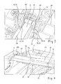
- Fig. 3
- eine perspektivische Draufsicht auf jenen Bereich des Bremssattels, an dem das eine Ende der Halteanordnung befestigt ist und
- Fig. 4
- eine perspektivische Draufsicht auf jenen Bereich des Bremssattels, an dem das andere Ende der Halteanordnung befestigt ist.
- Die
Fig. 1 zeigt den zentralen Teil des Bremssattels 1 einer Fahrzeug-Scheibenbremse für Nutzfahrzeuge. Die Scheibenbremse kann vom Gleitsattel-Bautyp oder vom Festsattel-Bautyp sein. Zu beiden Seiten der Bremsscheibe 2 sind Bremsbeläge 3 in dem Bremssattel 1 angeordnet. Zur Aufnahme der Bremsbeläge 3 ist der Bremssattel 1 mit einem Belagschacht 6 versehen, über den sich ein Niederhalter 10 erstreckt. Im Betriebszustand der Scheibenbremse überbrückt der Niederhalter 10 den Belagschacht 6. - Die Bremsbeläge 3 bestehen in üblicher Weise aus dem eigentlichen Reibbelag 4 sowie einer die Führung und Abstützung der Bremsbeläge im Belagschacht 6 übernehmenden Belagrückenplatte 5. Zwischen den Bremsbelägen befindet sich die Bremsscheibe 2 der Scheibenbremse.
- Der länglich gestaltete Niederhalter 10 erstreckt sich parallel zur Drehachse der Bremsscheibe 2 und damit zugleich rechtwinklig zu den Bremsbelägen 3. Beide Enden des Niederhalters 10 sind mittelbar oder unmittelbar am Bremssattel 1 der Scheibenbremse befestigbar. Zu diesem Zweck ragt das in
Fig. 1 links dargestellte eine Ende des Niederhalters 10 in eine Ausnehmung der Öffnung 7 des Bremssattels 1 hinein. Das andere, inFig. 1 rechts dargestellte Ende des Niederhalters 10 ist mittels eines Bolzens 8 lösbar am Bremssattel festgelegt. - Zur Sicherung der zwei Bremsbeläge 3 im Belagschacht besteht der Niederhalter 10 aus einem starren Haltebügel 11 und einer biegeelastischen Blattfeder 12. Der Haltebügel 11 weist einen Querschnitt mit einer den Bremsbelägen 3 zugewandten Unterseite auf, an die sich zu beiden Längsrändern 14, 15 hin Schrägen anschließen, wodurch der Haltebügel 11 einen in etwa trapezförmigen Querschnitt zeigt.
- Den Bremsbelägen 3 abgewandt weist der Haltebügel 11 eine Außenseite mit einer in etwa trapezförmigen Rinne auf. Mit seinen zwei Schrägen stützt er sich von außen auf den entsprechend gestalteten Rändern der Belagrückenplatten 5 ab, und hält auf diese Weise die Bremsbeläge 3 in dem Belagschacht 6, so dass die Bremsbeläge 3 nicht nach radial außen, bezogen auf die Drehachse der Bremsscheibe, aus dem Belagschacht 6 heraustreten oder herausfallen können.
- Die vorzugsweise aus Federstahl bestehende Blattfeder 12 ist über ihre Länge partiell gebogen. Auch sie ist mit ihren beiden Enden lösbar am Bremssattel festgelegt. Sie erstreckt sich längs des starren Haltebügels 11 und ist von außen gegen den Haltebügel 11 abgestützt. Die Abstützung ist dergestalt, dass sich die Blattfeder 12 nicht auf ihrer ganzen Länge, sondern nur auf der vergleichsweise kurzen Länge eines gebogenen Längsabschnitts 12a am ebenen Boden der Rinne des Haltebügels 11 abstützt, und daher auch nur an diesem Ort den Haltebügel mit einer Federkraft in Richtung auf die Bremsbeläge 3 beaufschlagt. Auf diese Weise stützt sich der Haltebügel 11 des Niederhalters 10, obwohl selbst starr, federnd gegen beide Belagrückenplatten 5 ab.
- Zur Detektion des im Fahrbetrieb zunehmenden Verschleißes der Reibbeläge 4 ist der fahrzeuginnen angeordnete Bremsbelag 3 (in
Fig. 1 rechts) mit einem Verschleißsensor 21, und der im Fahrbetrieb fahrzeugaußen angeordnete Bremsbelag 3 (inFig. 1 links) mit einem Verschleißsensor 22 versehen. Üblicherweise sind solche Verschleißsensoren 21, 22 in der jeweiligen Belagrückenplatte 5 verankert, und sie ragen mit ihrem Sensorelement in den Dickenbereich des Reibbelags 4. - Das elektrische Signal der Verschleißsensoren 21, 22 gelangt zu einer auf der Zeichnung nicht dargestellten Mess-, Anzeige- oder Auswerteeinheit. So kann z. B. dem Fahrer des Fahrzeugs ein zu stark abgenutzter Reibbelag durch eine entsprechende, in der Auswerteeinheit generierte Mitteilung angezeigt werden.
- Für den entsprechenden Signalweg führt ein Signalkabel 30 von den Verschleißsensoren 21, 22 zu einem außen an dem Bremssattel 1 befestigten Kontaktstecker 25, welcher seinerseits mit der Mess-, Anzeige- oder Auswerteeinheit verbindbar ist.
- Das Signalkabel 30 setzt sich hier aus zwei Kabelarmen 31, 32 zusammen, die nur auf einem Teil der Kabellänge gemeinsam geführt sind, hingegen auf dem übrigen Teil der Kabellänge als getrennte Kabelarme 31, 32, wobei der Kabelarm 32 deutlich länger als der Kabelarm 31 ist. Die Verzweigung 33 der beiden Kabelarme 31, 32 befindet sich, wie
Fig. 1 erkennen lässt, im Bereich des Bolzens 8, welcher das fahrzeuginnere Ende des Niederhalters 10 an dem Bremssattel 1 verriegelt. - Der längere Kabelarm 32 des Signalkabels 30 erstreckt sich quer über den Belagschacht 6 und längs des Niederhalters 10. Zur Positionierung dieses Kabelarms 32, aber auch des kürzeren Kabelarms 31, ist eine in
Fig. 2 näher wiedergegebene Halteanordnung 40 vorgesehen. Deren Bestandteile sind ein Haltedraht 45 und ein einen langgestreckten Halteabschnitt des Haltedrahts 45 umschließendes Führungselement 50 in Gestalt eines Röhrchens oder einer Hülse. - Die Hülse 50 kann aus Metall bestehen oder einem festen Kunststoff. Die Hülse 50 kann auch aus einem flexiblen Werkstoff bestehen. In diesem Fall übernimmt allein der Haltedraht 45 die Führungsfunktion hinsichtlich Lage und Ausrichtung der insoweit instabilen Hülse 50 und damit auch der Lage und Ausrichtung des hindurchführenden Signalkabelabschnitts.
- Gemäß
Fig. 2 ist der Haltedraht 45 durch entsprechende Biegeprozesse zweischenklig ausgebildet, wobei der sich längs des zweiten Kabelarms 31 erstreckende zweite Schenkel 46 kürzer ist, als der sich längs des Kabelarms 32 erstreckende Schenkel 47. Die Hülse 50, welche im Falle des Kabelarms 32 länger ist, als im Falle des Kabelarms 31, umschließt sowohl den jeweiligen Arm 31, 32 des Signalkabels 30, als auch den jeweiligen Halteabschnitt 47, 46 des Haltedrahts 45. - Eine Längsverbindung zwischen der jeweiligen Hülse 50 und dem Haltedraht 45 ist nicht erforderlich. Bevorzugt wird vielmehr, dass Hülse 50 und Haltedraht 45 frei längsbeweglich zueinander angeordnet sind. Auf diese Weise ist die Hülse 50 vom freien Ende des Schenkels 47, 46 auf diesen aufschiebbar.
- Der kürzere zweite Schenkel 46 des Haltedrahts ist von solcher Länge und Ausrichtung, dass er, teils umschlossen durch die Hülse 50, den kürzeren Kabelarm 31 führt, wobei für das Signalkabel genügend Flexibilität für die Bewegung des mit dem Verschleißsensor 21 versehenen, inneren Bremsbelags 3 während der Zustellung der Scheibenbremse verbleibt.
- Die Hülse 50 auf dem kürzeren Schenkel 46 kann, sofern sie aus einem flexiblem Material besteht, bis zum Sensor 21 reichen und sich an diesem abstützen. Dies vermeidet ihr Abrutschen von dem relativ kurzen Schenkel 46 mit zunehmendem Verschleiß am fahrzeuginneren Bremsbelag 3. Ausreichend ist, wenn der Schenkel 46 zumindest länger ist, als die mit der Zeit verschleißende Dicke der Reibbeläge 4.
- Der Schenkel 47 ist von solcher Länge und Ausrichtung, dass sich sein frei auslaufendes Drahtende 47A aus dem umschließenden Führungselement 50 hinaus erstreckt und in die an der Bremse vorhandene Ausnehmung 7 einsteckbar ist, in der auch das Ende des Niederhalters 10 sitzt.
- Zur bremsenfesten Montierbarkeit des Haltedrahts 45 weist dieser einen Befestigungsabschnitt 55 auf. Dieser setzt sich aus zwei federnd aufweitbaren Abschnitten des Haltedrahts 45 zusammen. Durch Aufweiten dieser Abschnitte lässt sich der Haltedraht 45 auf der Bremse bzw. hier auf dem zylindrisch gestalteten Bolzen 8 der Bremse aufklipsen.
- Um dem Haltedraht die entsprechende Federelastizität zu verleihen, besteht der Befestigungsabschnitt 55 aus zwei Ringsegmenten des Haltedrahts, die zueinander beabstandet und zueinander fluchtend ausgebildet sind. Jedes Ringsegment hat unter Freilassung einer Öffnung 56 einen Umschlingungswinkel, der größer als 180° ist und andererseits 300° nicht übersteigen sollte. Zur bremsfesten Montage der Halteanordnung 40 werden die Ringsegmente des Befestigungsabschnitts 55 kurz aufgeweitet und mit der Öffnung 56 zuerst von der Seite her auf den Bolzen 8 aufgesetzt, um so den Haltedraht 45 auf dem Bolzen 8 zu verklipsen.
- An den Befestigungsabschnitt 55 schließt sich der von dem Führungselement 50, also der Hülse, umgebene, langgestreckte Halteabschnitt 47 an. Dieser Halteabschnitt erstreckt sich bei montierter Halteanordnung längs des Niederhalters 10, wobei das frei auslaufende Drahtende 47A in der Ausnehmung 7 verriegelt ist.
- Für eine ausreichende Führung des Signalkabels hat die auf dem Halteabschnitt 47 angeordnete Hülse 50 vorzugsweise eine Länge von mindestens 50% der Länge des Haltedrahts 45, gemessen zwischen dem Befestigungsabschnitt 55 und dem Drahtende 47A.
-
- 1
- Bremssattel
- 2
- Bremsscheibe
- 3
- Bremsbelag
- 4
- Reibbelag
- 5
- Belagrückenplatte
- 6
- Belagschacht
- 7
- Ausnehmung
- 8
- Bolzen
- 10
- Niederhalter
- 11
- Haltebügel
- 12
- Blattfeder
- 12a
- gebogener Längsabschnitt der Blattfeder
- 14
- Längsrand
- 15
- Längsrand
- 21
- Verschleißsensor
- 22
- Verschleißsensor
- 25
- Kontaktstecker
- 30
- Signalkabel
- 31
- Kabelarm
- 32
- Kabelarm
- 33
- Verzweigung
- 40
- Halteanordnung
- 45
- Haltedraht
- 46
- kurzer Schenkel, Halteabschnitt
- 47
- langer Schenkel, Halteabschnitt
- 47A
- Drahtende
- 50
- Führungselement, Hülse
- 55
- Befestigungsabschnitt
- 56
- Öffnung
Claims (15)
- Halteanordnung für ein Signalkabel einer Bremsbelag-Verschleißsensierung, dessen eines Kabelende mit einem Verschleißsensor, und dessen anderes Kabelende mit einer Mess-, Anzeige- oder Auswerteeinheit verbindbar ist, mit einem zum Umschließen eines Längsabschnitts des Signalkabels ausgebildeten Führungselement (50), dadurch gekennzeichnet, dass das Führungselement (50) neben dem Signalkabel auch einen Längsabschnitt eines bremsenfest montierbaren Haltedrahts (45) umschließt.
- Halteanordnung nach Anspruch 1, dadurch gekennzeichnet, dass das Führungselement (50) als Hülse ausgebildet ist.
- Halteanordnung nach Anspruch 2, dadurch gekennzeichnet, dass die Hülse aus einem flexiblen und hitzebeständigen Material besteht.
- Halteanordnung nach einem der Ansprüche 1-3, dadurch gekennzeichnet, dass Führungselement (50) und Haltedraht (45) längsbeweglich zueinander angeordnet sind.
- Halteanordnung nach einem der vorangehenden Ansprüche, dadurch gekennzeichnet, dass das Führungselement (50) das Signalkabel und den Längsabschnitt des Haltedrahts (45) parallel zueinander umschließt.
- Halteanordnung nach einem der vorangehenden Ansprüche, dadurch gekennzeichnet, dass zur bremsenfesten Montierbarkeit des Haltedrahts (45) dieser mit einem Befestigungsabschnitt (55) versehen ist.
- Halteanordnung nach Anspruch 6, dadurch gekennzeichnet, dass der Haltedraht (45) im Anschluss an den Befestigungsabschnitt (55) mit einem langgestreckten Halteabschnitt (47) versehen ist, und dass das Führungselement (50) den Haltedraht (45) nur auf dem Halteabschnitt (47) umschließt.
- Halteanordnung nach Anspruch 6 oder 7, dadurch gekennzeichnet, dass sich der Haltedraht (45), dem Befestigungsabschnitt (55) abgewandt, bis zu einem frei auslaufenden Drahtende (47A) erstreckt.
- Halteanordnung nach Anspruch 8, dadurch gekennzeichnet, dass sich das frei auslaufende Drahtende (47A) aus dem umschließenden Führungselement (50) hinaus erstreckt und in eine an der Bremse vorhandene Ausnehmung oder Öffnung (7) einsteckbar ist.
- Halteanordnung nach einem der Ansprüche 6-9, dadurch gekennzeichnet, dass der Befestigungsabschnitt (55) als federnd aufweitbarer Längsabschnitt des Haltedrahts (45) ausgebildet ist.
- Halteanordnung nach Anspruch 10, dadurch gekennzeichnet, dass der Befestigungsabschnitt (55) als auf ein zylindrisches Bauteil, vorzugsweise einen Bolzen (8), der Bremse aufklipsbar ausgebildet ist.
- Halteanordnung nach Anspruch 11, dadurch gekennzeichnet, dass der Befestigungsabschnitt (55) des Haltedrahts (45) als ein eine Öffnung (56) freilassendes Ringsegment mit einem Umschlingungswinkel ausgebildet ist, der größer als 180° und nicht größer als 300° ist.
- Halteanordnung nach einem der vorangehenden Ansprüche, dadurch gekennzeichnet, dass der Haltedraht (45) zweischenklig ist, wobei die zwei Schenkel (46, 47) von unterschiedlicher Länge sind und sich auf jedem Schenkel ein Führungselement (50) befindet.
- Halteanordnung nach Anspruch 13, dadurch gekennzeichnet, dass die Führungselemente (50) von unterschiedlicher Länge sind, wobei sich das längere Führungselement auf dem längeren Schenkel (47), und das kürzere Führungselement auf dem kürzeren Schenkel (46) befindet.
- Halteanordnung nach Anspruch 13 oder 14, dadurch gekennzeichnet, dass sich das Ende (47A) des längeren Schenkels (47) aus dem diesen umschließenden Führungselement (50) hinaus erstreckt, und in eine an der Bremse vorhandene Ausnehmung oder Öffnung (7) einsteckbar ist.
Applications Claiming Priority (1)
| Application Number | Priority Date | Filing Date | Title |
|---|---|---|---|
| DE102012106424.5A DE102012106424A1 (de) | 2012-07-17 | 2012-07-17 | Halteanordnung für ein Signalkabel einer Bremsbelag-Verschleißsensierung |
Publications (3)
| Publication Number | Publication Date |
|---|---|
| EP2687746A1 true EP2687746A1 (de) | 2014-01-22 |
| EP2687746B1 EP2687746B1 (de) | 2014-11-12 |
| EP2687746B2 EP2687746B2 (de) | 2021-06-30 |
Family
ID=48740913
Family Applications (1)
| Application Number | Title | Priority Date | Filing Date |
|---|---|---|---|
| EP13174538.2A Active EP2687746B2 (de) | 2012-07-17 | 2013-07-01 | Halteanordnung für ein Signalkabel einer Bremsbelag-Verschleißsensierung |
Country Status (3)
| Country | Link |
|---|---|
| EP (1) | EP2687746B2 (de) |
| DE (1) | DE102012106424A1 (de) |
| ES (1) | ES2528904T5 (de) |
Cited By (5)
| Publication number | Priority date | Publication date | Assignee | Title |
|---|---|---|---|---|
| US20150041258A1 (en) * | 2012-04-27 | 2015-02-12 | Knorr-Bremse Systeme Fuer Nutzfahrzeuge Gmbh | Mount for a Contact Conductor of a Device for Monitoring Brake Pad Wear |
| DE102014105561A1 (de) | 2014-04-17 | 2015-10-22 | Bpw Bergische Achsen Kg | Bremsbelag-Anordnung für eine Fahrzeugbremse sowie Fahrzeugbremse |
| EP2997280B1 (de) | 2013-05-13 | 2017-07-19 | KNORR-BREMSE Systeme für Nutzfahrzeuge GmbH | Bremsbelaghalterung einer scheibenbremse |
| WO2018050264A1 (de) * | 2016-09-15 | 2018-03-22 | Wabco Europe Bvba | Verschleissüberwachungsvorrichtung, ergänzungsmodul für eine verschleissüberwachungsvorrichtung sowie scheibenbremse mit einer solchen verschleissüberwachungsvorrichtung oder mit einem solchen ergänzungsmodul |
| CN108350959A (zh) * | 2015-10-27 | 2018-07-31 | Bpw 矿用轴公司 | 盘式制动器以及用于盘式制动器的制动衬块的压紧组件的板簧 |
Families Citing this family (2)
| Publication number | Priority date | Publication date | Assignee | Title |
|---|---|---|---|---|
| WO2017174507A1 (de) * | 2016-04-04 | 2017-10-12 | Knorr-Bremse Systeme für Nutzfahrzeuge GmbH | Befestigungsvorrichtung zur befestigung eines signalkabels |
| DE102021102324B4 (de) * | 2021-02-02 | 2023-10-19 | Saf-Holland Gmbh | Belagniederhalteranordnung, Bremssattelanordnung, Scheibenbremse und Scheibenbremsüberwachungssystem |
Citations (5)
| Publication number | Priority date | Publication date | Assignee | Title |
|---|---|---|---|---|
| EP0190705A2 (de) * | 1985-02-04 | 1986-08-13 | LUCAS INDUSTRIES public limited company | Verschleissanzeigevorrichtung für Bremsbeläge |
| DE4340452A1 (de) * | 1993-11-27 | 1995-06-01 | Teves Gmbh Alfred | Schwimmsattel-Scheibenbremse mit Verschleißwarnvorrichtung |
| DE19505318A1 (de) * | 1995-02-17 | 1996-08-22 | Teves Gmbh Alfred | Niederhaltefeder für Scheibenbremsen |
| EP0602866B1 (de) | 1992-12-15 | 1997-03-05 | Lucas Industries Public Limited Company | Aufbau einer Bremsbelagverschleissanzeige |
| DE102011012271B3 (de) * | 2011-02-24 | 2012-06-21 | Knorr-Bremse Systeme für Nutzfahrzeuge GmbH | Befestigung eines Kontaktleiters einer Vorrichtung zur Überwachung eines Bremsbelagverschleißes |
Family Cites Families (6)
| Publication number | Priority date | Publication date | Assignee | Title |
|---|---|---|---|---|
| US3716113A (en) † | 1969-11-01 | 1973-02-13 | Aisin Seiki | Warning device for indicating wear of friction pads in disk brake |
| US4188613A (en) † | 1978-05-31 | 1980-02-12 | Wong Chia Hsiang | Safety indicator for automobile braking system |
| IT236284Y1 (it) † | 1997-07-18 | 2000-08-08 | I C P Srl | Elemento di connessione elettrica, particolarmente per cablaggi dirilevatori d'usura per pastiglie freno. |
| DE10211813B4 (de) † | 2002-03-16 | 2006-01-19 | Knorr-Bremse Systeme für Nutzfahrzeuge GmbH | Verfahren und Vorrichtung zur Überprüfung der Funktionssicherheit von Verschleiß- und/oder Funktionsteilen einer Scheibenbremse |
| DE102005060551B4 (de) * | 2005-12-17 | 2010-05-06 | MAN Nutzfahrzeuge Österreich AG | Vorrichtung zur Anzeige eines Bremsbelagverschleißes |
| DE102008021008A1 (de) * | 2008-04-25 | 2009-10-29 | Bpw Bergische Achsen Kg | Niederhalter für die Bremsbeläge einer Scheibenbremse sowie Kabelhalter hierfür |
-
2012
- 2012-07-17 DE DE102012106424.5A patent/DE102012106424A1/de not_active Withdrawn
-
2013
- 2013-07-01 EP EP13174538.2A patent/EP2687746B2/de active Active
- 2013-07-01 ES ES13174538T patent/ES2528904T5/es active Active
Patent Citations (5)
| Publication number | Priority date | Publication date | Assignee | Title |
|---|---|---|---|---|
| EP0190705A2 (de) * | 1985-02-04 | 1986-08-13 | LUCAS INDUSTRIES public limited company | Verschleissanzeigevorrichtung für Bremsbeläge |
| EP0602866B1 (de) | 1992-12-15 | 1997-03-05 | Lucas Industries Public Limited Company | Aufbau einer Bremsbelagverschleissanzeige |
| DE4340452A1 (de) * | 1993-11-27 | 1995-06-01 | Teves Gmbh Alfred | Schwimmsattel-Scheibenbremse mit Verschleißwarnvorrichtung |
| DE19505318A1 (de) * | 1995-02-17 | 1996-08-22 | Teves Gmbh Alfred | Niederhaltefeder für Scheibenbremsen |
| DE102011012271B3 (de) * | 2011-02-24 | 2012-06-21 | Knorr-Bremse Systeme für Nutzfahrzeuge GmbH | Befestigung eines Kontaktleiters einer Vorrichtung zur Überwachung eines Bremsbelagverschleißes |
Cited By (8)
| Publication number | Priority date | Publication date | Assignee | Title |
|---|---|---|---|---|
| US20150041258A1 (en) * | 2012-04-27 | 2015-02-12 | Knorr-Bremse Systeme Fuer Nutzfahrzeuge Gmbh | Mount for a Contact Conductor of a Device for Monitoring Brake Pad Wear |
| EP2997280B1 (de) | 2013-05-13 | 2017-07-19 | KNORR-BREMSE Systeme für Nutzfahrzeuge GmbH | Bremsbelaghalterung einer scheibenbremse |
| DE102014105561A1 (de) | 2014-04-17 | 2015-10-22 | Bpw Bergische Achsen Kg | Bremsbelag-Anordnung für eine Fahrzeugbremse sowie Fahrzeugbremse |
| CN108350959A (zh) * | 2015-10-27 | 2018-07-31 | Bpw 矿用轴公司 | 盘式制动器以及用于盘式制动器的制动衬块的压紧组件的板簧 |
| US10677301B2 (en) | 2015-10-27 | 2020-06-09 | Bpw Bergische Achsen Kg | Disc brake, and flat spring of a hold-down assembly for the brake pads of a disc brake |
| WO2018050264A1 (de) * | 2016-09-15 | 2018-03-22 | Wabco Europe Bvba | Verschleissüberwachungsvorrichtung, ergänzungsmodul für eine verschleissüberwachungsvorrichtung sowie scheibenbremse mit einer solchen verschleissüberwachungsvorrichtung oder mit einem solchen ergänzungsmodul |
| WO2018050272A3 (de) * | 2016-09-15 | 2018-07-05 | Wabco Europe Bvba | Verschleissüberwachungsvorrichtung und scheibenbremse mit einer solchen verschleissüberwachungsvorrichtung |
| US11137042B2 (en) | 2016-09-15 | 2021-10-05 | Wabco Europe Bvba | Wear monitoring device and disk brake having a wear monitoring device |
Also Published As
| Publication number | Publication date |
|---|---|
| DE102012106424A1 (de) | 2014-01-23 |
| EP2687746B2 (de) | 2021-06-30 |
| ES2528904T5 (es) | 2021-12-03 |
| ES2528904T3 (es) | 2015-02-13 |
| EP2687746B1 (de) | 2014-11-12 |
Similar Documents
| Publication | Publication Date | Title |
|---|---|---|
| EP2687746B1 (de) | Halteanordnung für ein Signalkabel einer Bremsbelag-Verschleißsensierung | |
| EP3359843B1 (de) | Scheibenbremse für ein nutzfahrzeug | |
| DE102010048988B4 (de) | Scheibenbremse mit Bremsbelagverschleißanzeige und Bremsbacken für eine solche Scheibenbremse | |
| EP2761201B1 (de) | Scheibenbremse, insbesondere für nutzfahrzeuge, sowie niederhaltefeder einer solchen scheibenbremse | |
| EP2685124B1 (de) | Scheibenbremse für ein Nutzfahrzeug | |
| EP2664815B1 (de) | Scheibenbremse, insbesondere für Nutzfahrzeuge | |
| EP2112397A1 (de) | Niederhalter für die Bremsbeläge einer Scheibenbremse sowie Kabelhalter hierfür | |
| EP3684672B1 (de) | Dehnungsmessanordnung, insbesondere für einen achszähler | |
| EP2900854B1 (de) | Fixkammbefestigung | |
| WO2016034377A1 (de) | Scheibenbremse eines kraftfahrzeugs, bremssattel, bremsbelag und anordnung wenigstens eines bremsbelags in einer belagschachtöffnung eines bremssattels | |
| EP4141282A1 (de) | Scheibenbremse für ein kraftfahrzeug | |
| DE102007016393A1 (de) | Bremsbelaghalterung und Bremsbelag für eine Scheibenbremse | |
| DE102009025875A1 (de) | Vorrichtung zur Erfassung des Reibbelagverschleißes sowie Stab hierfür | |
| EP2824352B1 (de) | Bremsbelaghalterung einer Scheibenbremse für ein Nutzfahrzeug | |
| DE4340452A1 (de) | Schwimmsattel-Scheibenbremse mit Verschleißwarnvorrichtung | |
| DE102012110461A1 (de) | Bremsbelag für eine Scheibenbremse | |
| EP3368787B1 (de) | Scheibenbremse, sowie blattfeder und befestigungsbügel einer niederhalteranordnung für die bremsbeläge einer scheibenbremse | |
| DE4402071B4 (de) | Umlenkzahnrad für ein Förderband | |
| DE10019654A1 (de) | Scheibenbremse | |
| EP1158199B1 (de) | Belagverschleissanzeigevorrichtung für Scheibenbremsen | |
| DE4424084C2 (de) | Bremsbelagverschleißanzeiger | |
| EP1643806B1 (de) | Heizelement | |
| DE102011115466A1 (de) | Scheibenbremse für ein Nutzfahrzeug | |
| EP2287489B1 (de) | Vorrichtung zum Befestigen eines elektrischen Bauteils einer Fahrzeugbremse | |
| EP3199828A1 (de) | Bremsbelaghalterung einer fahrzeug-scheibenbremse sowie niederhalter für die befestigung von bremsbelägen |
Legal Events
| Date | Code | Title | Description |
|---|---|---|---|
| PUAI | Public reference made under article 153(3) epc to a published international application that has entered the european phase |
Free format text: ORIGINAL CODE: 0009012 |
|
| AK | Designated contracting states |
Kind code of ref document: A1 Designated state(s): AL AT BE BG CH CY CZ DE DK EE ES FI FR GB GR HR HU IE IS IT LI LT LU LV MC MK MT NL NO PL PT RO RS SE SI SK SM TR |
|
| AX | Request for extension of the european patent |
Extension state: BA ME |
|
| 17P | Request for examination filed |
Effective date: 20140305 |
|
| RBV | Designated contracting states (corrected) |
Designated state(s): AL AT BE BG CH CY CZ DE DK EE ES FI FR GB GR HR HU IE IS IT LI LT LU LV MC MK MT NL NO PL PT RO RS SE SI SK SM TR |
|
| GRAP | Despatch of communication of intention to grant a patent |
Free format text: ORIGINAL CODE: EPIDOSNIGR1 |
|
| INTG | Intention to grant announced |
Effective date: 20140530 |
|
| GRAS | Grant fee paid |
Free format text: ORIGINAL CODE: EPIDOSNIGR3 |
|
| GRAA | (expected) grant |
Free format text: ORIGINAL CODE: 0009210 |
|
| STAA | Information on the status of an ep patent application or granted ep patent |
Free format text: STATUS: THE PATENT HAS BEEN GRANTED |
|
| AK | Designated contracting states |
Kind code of ref document: B1 Designated state(s): AL AT BE BG CH CY CZ DE DK EE ES FI FR GB GR HR HU IE IS IT LI LT LU LV MC MK MT NL NO PL PT RO RS SE SI SK SM TR |
|
| REG | Reference to a national code |
Ref country code: GB Ref legal event code: FG4D Free format text: NOT ENGLISH |
|
| REG | Reference to a national code |
Ref country code: CH Ref legal event code: EP |
|
| REG | Reference to a national code |
Ref country code: AT Ref legal event code: REF Ref document number: 695966 Country of ref document: AT Kind code of ref document: T Effective date: 20141115 |
|
| REG | Reference to a national code |
Ref country code: IE Ref legal event code: FG4D Free format text: LANGUAGE OF EP DOCUMENT: GERMAN |
|
| REG | Reference to a national code |
Ref country code: DE Ref legal event code: R096 Ref document number: 502013000177 Country of ref document: DE Effective date: 20141231 |
|
| REG | Reference to a national code |
Ref country code: ES Ref legal event code: FG2A Ref document number: 2528904 Country of ref document: ES Kind code of ref document: T3 Effective date: 20150213 |
|
| REG | Reference to a national code |
Ref country code: NL Ref legal event code: VDEP Effective date: 20141112 |
|
| PG25 | Lapsed in a contracting state [announced via postgrant information from national office to epo] |
Ref country code: IS Free format text: LAPSE BECAUSE OF FAILURE TO SUBMIT A TRANSLATION OF THE DESCRIPTION OR TO PAY THE FEE WITHIN THE PRESCRIBED TIME-LIMIT Effective date: 20150312 Ref country code: PT Free format text: LAPSE BECAUSE OF FAILURE TO SUBMIT A TRANSLATION OF THE DESCRIPTION OR TO PAY THE FEE WITHIN THE PRESCRIBED TIME-LIMIT Effective date: 20150312 Ref country code: FI Free format text: LAPSE BECAUSE OF FAILURE TO SUBMIT A TRANSLATION OF THE DESCRIPTION OR TO PAY THE FEE WITHIN THE PRESCRIBED TIME-LIMIT Effective date: 20141112 Ref country code: NO Free format text: LAPSE BECAUSE OF FAILURE TO SUBMIT A TRANSLATION OF THE DESCRIPTION OR TO PAY THE FEE WITHIN THE PRESCRIBED TIME-LIMIT Effective date: 20150212 Ref country code: LT Free format text: LAPSE BECAUSE OF FAILURE TO SUBMIT A TRANSLATION OF THE DESCRIPTION OR TO PAY THE FEE WITHIN THE PRESCRIBED TIME-LIMIT Effective date: 20141112 Ref country code: NL Free format text: LAPSE BECAUSE OF FAILURE TO SUBMIT A TRANSLATION OF THE DESCRIPTION OR TO PAY THE FEE WITHIN THE PRESCRIBED TIME-LIMIT Effective date: 20141112 |
|
| PG25 | Lapsed in a contracting state [announced via postgrant information from national office to epo] |
Ref country code: GR Free format text: LAPSE BECAUSE OF FAILURE TO SUBMIT A TRANSLATION OF THE DESCRIPTION OR TO PAY THE FEE WITHIN THE PRESCRIBED TIME-LIMIT Effective date: 20150213 Ref country code: PL Free format text: LAPSE BECAUSE OF FAILURE TO SUBMIT A TRANSLATION OF THE DESCRIPTION OR TO PAY THE FEE WITHIN THE PRESCRIBED TIME-LIMIT Effective date: 20141112 Ref country code: RS Free format text: LAPSE BECAUSE OF FAILURE TO SUBMIT A TRANSLATION OF THE DESCRIPTION OR TO PAY THE FEE WITHIN THE PRESCRIBED TIME-LIMIT Effective date: 20141112 Ref country code: CY Free format text: LAPSE BECAUSE OF FAILURE TO SUBMIT A TRANSLATION OF THE DESCRIPTION OR TO PAY THE FEE WITHIN THE PRESCRIBED TIME-LIMIT Effective date: 20141112 Ref country code: LV Free format text: LAPSE BECAUSE OF FAILURE TO SUBMIT A TRANSLATION OF THE DESCRIPTION OR TO PAY THE FEE WITHIN THE PRESCRIBED TIME-LIMIT Effective date: 20141112 Ref country code: SE Free format text: LAPSE BECAUSE OF FAILURE TO SUBMIT A TRANSLATION OF THE DESCRIPTION OR TO PAY THE FEE WITHIN THE PRESCRIBED TIME-LIMIT Effective date: 20141112 Ref country code: HR Free format text: LAPSE BECAUSE OF FAILURE TO SUBMIT A TRANSLATION OF THE DESCRIPTION OR TO PAY THE FEE WITHIN THE PRESCRIBED TIME-LIMIT Effective date: 20141112 |
|
| PG25 | Lapsed in a contracting state [announced via postgrant information from national office to epo] |
Ref country code: EE Free format text: LAPSE BECAUSE OF FAILURE TO SUBMIT A TRANSLATION OF THE DESCRIPTION OR TO PAY THE FEE WITHIN THE PRESCRIBED TIME-LIMIT Effective date: 20141112 Ref country code: CZ Free format text: LAPSE BECAUSE OF FAILURE TO SUBMIT A TRANSLATION OF THE DESCRIPTION OR TO PAY THE FEE WITHIN THE PRESCRIBED TIME-LIMIT Effective date: 20141112 Ref country code: RO Free format text: LAPSE BECAUSE OF FAILURE TO SUBMIT A TRANSLATION OF THE DESCRIPTION OR TO PAY THE FEE WITHIN THE PRESCRIBED TIME-LIMIT Effective date: 20141112 Ref country code: DK Free format text: LAPSE BECAUSE OF FAILURE TO SUBMIT A TRANSLATION OF THE DESCRIPTION OR TO PAY THE FEE WITHIN THE PRESCRIBED TIME-LIMIT Effective date: 20141112 Ref country code: SK Free format text: LAPSE BECAUSE OF FAILURE TO SUBMIT A TRANSLATION OF THE DESCRIPTION OR TO PAY THE FEE WITHIN THE PRESCRIBED TIME-LIMIT Effective date: 20141112 |
|
| REG | Reference to a national code |
Ref country code: DE Ref legal event code: R026 Ref document number: 502013000177 Country of ref document: DE |
|
| PLBI | Opposition filed |
Free format text: ORIGINAL CODE: 0009260 |
|
| 26 | Opposition filed |
Opponent name: VRI-VERBAND DER REIBBELAGINDUSTRIE E.V. Effective date: 20150811 |
|
| PLAX | Notice of opposition and request to file observation + time limit sent |
Free format text: ORIGINAL CODE: EPIDOSNOBS2 |
|
| PLBB | Reply of patent proprietor to notice(s) of opposition received |
Free format text: ORIGINAL CODE: EPIDOSNOBS3 |
|
| PG25 | Lapsed in a contracting state [announced via postgrant information from national office to epo] |
Ref country code: SI Free format text: LAPSE BECAUSE OF FAILURE TO SUBMIT A TRANSLATION OF THE DESCRIPTION OR TO PAY THE FEE WITHIN THE PRESCRIBED TIME-LIMIT Effective date: 20141112 Ref country code: MC Free format text: LAPSE BECAUSE OF FAILURE TO SUBMIT A TRANSLATION OF THE DESCRIPTION OR TO PAY THE FEE WITHIN THE PRESCRIBED TIME-LIMIT Effective date: 20141112 |
|
| PG25 | Lapsed in a contracting state [announced via postgrant information from national office to epo] |
Ref country code: LU Free format text: LAPSE BECAUSE OF FAILURE TO SUBMIT A TRANSLATION OF THE DESCRIPTION OR TO PAY THE FEE WITHIN THE PRESCRIBED TIME-LIMIT Effective date: 20150701 |
|
| REG | Reference to a national code |
Ref country code: IE Ref legal event code: MM4A |
|
| REG | Reference to a national code |
Ref country code: FR Ref legal event code: PLFP Year of fee payment: 4 |
|
| PG25 | Lapsed in a contracting state [announced via postgrant information from national office to epo] |
Ref country code: IE Free format text: LAPSE BECAUSE OF NON-PAYMENT OF DUE FEES Effective date: 20150701 |
|
| REG | Reference to a national code |
Ref country code: CH Ref legal event code: PL |
|
| PG25 | Lapsed in a contracting state [announced via postgrant information from national office to epo] |
Ref country code: MT Free format text: LAPSE BECAUSE OF FAILURE TO SUBMIT A TRANSLATION OF THE DESCRIPTION OR TO PAY THE FEE WITHIN THE PRESCRIBED TIME-LIMIT Effective date: 20141112 |
|
| PG25 | Lapsed in a contracting state [announced via postgrant information from national office to epo] |
Ref country code: CH Free format text: LAPSE BECAUSE OF NON-PAYMENT OF DUE FEES Effective date: 20160731 Ref country code: LI Free format text: LAPSE BECAUSE OF NON-PAYMENT OF DUE FEES Effective date: 20160731 |
|
| PG25 | Lapsed in a contracting state [announced via postgrant information from national office to epo] |
Ref country code: HU Free format text: LAPSE BECAUSE OF FAILURE TO SUBMIT A TRANSLATION OF THE DESCRIPTION OR TO PAY THE FEE WITHIN THE PRESCRIBED TIME-LIMIT; INVALID AB INITIO Effective date: 20130701 Ref country code: BG Free format text: LAPSE BECAUSE OF FAILURE TO SUBMIT A TRANSLATION OF THE DESCRIPTION OR TO PAY THE FEE WITHIN THE PRESCRIBED TIME-LIMIT Effective date: 20141112 |
|
| REG | Reference to a national code |
Ref country code: FR Ref legal event code: PLFP Year of fee payment: 5 |
|
| PG25 | Lapsed in a contracting state [announced via postgrant information from national office to epo] |
Ref country code: BE Free format text: LAPSE BECAUSE OF NON-PAYMENT OF DUE FEES Effective date: 20150731 |
|
| APBM | Appeal reference recorded |
Free format text: ORIGINAL CODE: EPIDOSNREFNO |
|
| APBP | Date of receipt of notice of appeal recorded |
Free format text: ORIGINAL CODE: EPIDOSNNOA2O |
|
| APAH | Appeal reference modified |
Free format text: ORIGINAL CODE: EPIDOSCREFNO |
|
| APBQ | Date of receipt of statement of grounds of appeal recorded |
Free format text: ORIGINAL CODE: EPIDOSNNOA3O |
|
| PG25 | Lapsed in a contracting state [announced via postgrant information from national office to epo] |
Ref country code: SM Free format text: LAPSE BECAUSE OF FAILURE TO SUBMIT A TRANSLATION OF THE DESCRIPTION OR TO PAY THE FEE WITHIN THE PRESCRIBED TIME-LIMIT Effective date: 20141112 |
|
| PG25 | Lapsed in a contracting state [announced via postgrant information from national office to epo] |
Ref country code: MK Free format text: LAPSE BECAUSE OF FAILURE TO SUBMIT A TRANSLATION OF THE DESCRIPTION OR TO PAY THE FEE WITHIN THE PRESCRIBED TIME-LIMIT Effective date: 20141112 |
|
| REG | Reference to a national code |
Ref country code: FR Ref legal event code: PLFP Year of fee payment: 6 |
|
| PG25 | Lapsed in a contracting state [announced via postgrant information from national office to epo] |
Ref country code: AL Free format text: LAPSE BECAUSE OF FAILURE TO SUBMIT A TRANSLATION OF THE DESCRIPTION OR TO PAY THE FEE WITHIN THE PRESCRIBED TIME-LIMIT Effective date: 20141112 |
|
| REG | Reference to a national code |
Ref country code: AT Ref legal event code: MM01 Ref document number: 695966 Country of ref document: AT Kind code of ref document: T Effective date: 20180701 |
|
| PG25 | Lapsed in a contracting state [announced via postgrant information from national office to epo] |
Ref country code: AT Free format text: LAPSE BECAUSE OF NON-PAYMENT OF DUE FEES Effective date: 20180701 |
|
| APBU | Appeal procedure closed |
Free format text: ORIGINAL CODE: EPIDOSNNOA9O |
|
| PUAH | Patent maintained in amended form |
Free format text: ORIGINAL CODE: 0009272 |
|
| STAA | Information on the status of an ep patent application or granted ep patent |
Free format text: STATUS: PATENT MAINTAINED AS AMENDED |
|
| 27A | Patent maintained in amended form |
Effective date: 20210630 |
|
| AK | Designated contracting states |
Kind code of ref document: B2 Designated state(s): AL AT BE BG CH CY CZ DE DK EE ES FI FR GB GR HR HU IE IS IT LI LT LU LV MC MK MT NL NO PL PT RO RS SE SI SK SM TR |
|
| REG | Reference to a national code |
Ref country code: DE Ref legal event code: R102 Ref document number: 502013000177 Country of ref document: DE |
|
| REG | Reference to a national code |
Ref country code: ES Ref legal event code: DC2A Ref document number: 2528904 Country of ref document: ES Kind code of ref document: T5 Effective date: 20211203 |
|
| REG | Reference to a national code |
Ref country code: DE Ref legal event code: R082 Ref document number: 502013000177 Country of ref document: DE Representative=s name: DREISS PATENTANWAELTE PARTG MBB, DE Ref country code: DE Ref legal event code: R082 Ref document number: 502013000177 Country of ref document: DE Representative=s name: JANKE SCHOLL PATENTANWAELTE PARTG MBB, DE |
|
| REG | Reference to a national code |
Ref country code: DE Ref legal event code: R082 Ref document number: 502013000177 Country of ref document: DE Representative=s name: DREISS PATENTANWAELTE PARTG MBB, DE |
|
| PGFP | Annual fee paid to national office [announced via postgrant information from national office to epo] |
Ref country code: TR Payment date: 20220624 Year of fee payment: 10 |
|
| PGFP | Annual fee paid to national office [announced via postgrant information from national office to epo] |
Ref country code: IT Payment date: 20220729 Year of fee payment: 10 Ref country code: GB Payment date: 20220725 Year of fee payment: 10 Ref country code: ES Payment date: 20220819 Year of fee payment: 10 |
|
| PGFP | Annual fee paid to national office [announced via postgrant information from national office to epo] |
Ref country code: FR Payment date: 20220727 Year of fee payment: 10 |
|
| P01 | Opt-out of the competence of the unified patent court (upc) registered |
Effective date: 20230508 |
|
| PGFP | Annual fee paid to national office [announced via postgrant information from national office to epo] |
Ref country code: DE Payment date: 20230912 Year of fee payment: 11 |
|
| GBPC | Gb: european patent ceased through non-payment of renewal fee |
Effective date: 20230701 |
|
| PG25 | Lapsed in a contracting state [announced via postgrant information from national office to epo] |
Ref country code: GB Free format text: LAPSE BECAUSE OF NON-PAYMENT OF DUE FEES Effective date: 20230701 |