EP2687645A1 - Verbindungselement von Bauteilen, insbesondere Tafeln und Trägern - Google Patents
Verbindungselement von Bauteilen, insbesondere Tafeln und Trägern Download PDFInfo
- Publication number
- EP2687645A1 EP2687645A1 EP13177095.0A EP13177095A EP2687645A1 EP 2687645 A1 EP2687645 A1 EP 2687645A1 EP 13177095 A EP13177095 A EP 13177095A EP 2687645 A1 EP2687645 A1 EP 2687645A1
- Authority
- EP
- European Patent Office
- Prior art keywords
- connecting element
- element according
- filling material
- anchoring
- figur
- Prior art date
- Legal status (The legal status is an assumption and is not a legal conclusion. Google has not performed a legal analysis and makes no representation as to the accuracy of the status listed.)
- Granted
Links
Images




Classifications
-
- E—FIXED CONSTRUCTIONS
- E04—BUILDING
- E04B—GENERAL BUILDING CONSTRUCTIONS; WALLS, e.g. PARTITIONS; ROOFS; FLOORS; CEILINGS; INSULATION OR OTHER PROTECTION OF BUILDINGS
- E04B1/00—Constructions in general; Structures which are not restricted either to walls, e.g. partitions, or floors or ceilings or roofs
- E04B1/02—Structures consisting primarily of load-supporting, block-shaped, or slab-shaped elements
- E04B1/04—Structures consisting primarily of load-supporting, block-shaped, or slab-shaped elements the elements consisting of concrete, e.g. reinforced concrete, or other stone-like material
- E04B1/043—Connections specially adapted therefor
-
- E—FIXED CONSTRUCTIONS
- E04—BUILDING
- E04B—GENERAL BUILDING CONSTRUCTIONS; WALLS, e.g. PARTITIONS; ROOFS; FLOORS; CEILINGS; INSULATION OR OTHER PROTECTION OF BUILDINGS
- E04B1/00—Constructions in general; Structures which are not restricted either to walls, e.g. partitions, or floors or ceilings or roofs
- E04B1/02—Structures consisting primarily of load-supporting, block-shaped, or slab-shaped elements
- E04B1/10—Structures consisting primarily of load-supporting, block-shaped, or slab-shaped elements the elements consisting of wood
-
- E—FIXED CONSTRUCTIONS
- E04—BUILDING
- E04B—GENERAL BUILDING CONSTRUCTIONS; WALLS, e.g. PARTITIONS; ROOFS; FLOORS; CEILINGS; INSULATION OR OTHER PROTECTION OF BUILDINGS
- E04B1/00—Constructions in general; Structures which are not restricted either to walls, e.g. partitions, or floors or ceilings or roofs
- E04B1/18—Structures comprising elongated load-supporting parts, e.g. columns, girders, skeletons
- E04B1/20—Structures comprising elongated load-supporting parts, e.g. columns, girders, skeletons the supporting parts consisting of concrete, e.g. reinforced concrete, or other stonelike material
- E04B1/21—Connections specially adapted therefor
-
- E—FIXED CONSTRUCTIONS
- E04—BUILDING
- E04B—GENERAL BUILDING CONSTRUCTIONS; WALLS, e.g. PARTITIONS; ROOFS; FLOORS; CEILINGS; INSULATION OR OTHER PROTECTION OF BUILDINGS
- E04B1/00—Constructions in general; Structures which are not restricted either to walls, e.g. partitions, or floors or ceilings or roofs
- E04B1/18—Structures comprising elongated load-supporting parts, e.g. columns, girders, skeletons
- E04B1/26—Structures comprising elongated load-supporting parts, e.g. columns, girders, skeletons the supporting parts consisting of wood
- E04B1/2604—Connections specially adapted therefor
-
- E—FIXED CONSTRUCTIONS
- E04—BUILDING
- E04B—GENERAL BUILDING CONSTRUCTIONS; WALLS, e.g. PARTITIONS; ROOFS; FLOORS; CEILINGS; INSULATION OR OTHER PROTECTION OF BUILDINGS
- E04B1/00—Constructions in general; Structures which are not restricted either to walls, e.g. partitions, or floors or ceilings or roofs
- E04B1/38—Connections for building structures in general
- E04B1/61—Connections for building structures in general of slab-shaped building elements with each other
- E04B1/6108—Connections for building structures in general of slab-shaped building elements with each other the frontal surfaces of the slabs connected together
- E04B2001/6191—Connections for building structures in general of slab-shaped building elements with each other the frontal surfaces of the slabs connected together by means on the corners of the slabs
-
- F—MECHANICAL ENGINEERING; LIGHTING; HEATING; WEAPONS; BLASTING
- F16—ENGINEERING ELEMENTS AND UNITS; GENERAL MEASURES FOR PRODUCING AND MAINTAINING EFFECTIVE FUNCTIONING OF MACHINES OR INSTALLATIONS; THERMAL INSULATION IN GENERAL
- F16B—DEVICES FOR FASTENING OR SECURING CONSTRUCTIONAL ELEMENTS OR MACHINE PARTS TOGETHER, e.g. NAILS, BOLTS, CIRCLIPS, CLAMPS, CLIPS OR WEDGES; JOINTS OR JOINTING
- F16B3/00—Key-type connections; Keys
- F16B3/005—Key-type connections; Keys the key being formed by solidification of injected material
Definitions
- the invention relates to a connecting element of components, in particular panels and carriers.
- Another solution provides elements that are connected in advance with components and fastened together in a second step.
- elements are known that are spaced apart on a device surface. These strip-shaped elements have a trapezoidal shape and have on the inclined sides through holes. These holes are formed so that the screw head is inserted so that the head is completely absorbed. In this way, the screw head is aligned flush with the inclined surface. Above the head of the screw, a lid is placed to prevent possible impacts intercept.
- This system is very complicated and, moreover, the smallest games are required. There is a lot of play between the screw head and the cover, the loaded screw could be loosened and therefore have a low strength. The total loads on both the train and the press are concentrated on the screw head and there is no interaction between the fastener and the surface.
- the EP 0 442 243 describes an assembly and a disassembly device comprising at least one sound attenuation element.
- the connecting element of components according to the invention has the aim of carrying out a stable, quickly executable connection, where the loads are distributed on a surface.
- This object is achieved by a connecting element for connecting components, which is arranged opposite on the surface of the component, wherein the connecting element comprises a body, wherein the body comprises a shell and has filling material that is designed to be more elastic than the material forming the shell, wherein the sheath and the filling material are capable of receiving continuous and attachable in the components anchoring elements.
- the body of the element according to the invention has a shell.
- This metal shell fulfills the task of ensuring the stability of the entire element.
- the filling material comes into contact with the anchoring element, for example a screw.
- This contact may be provided by a thread provided in the through bore in the filler or may be by the anchoring element itself which is self-threaded through the filler.
- the contact may be given by the adhesion of the filling compound to the anchoring element in the case where the filling material is a bonding material.
- the bonding material may be, for example, a foam or a resin, which is introduced into the shell after connection.
- the anchoring elements are positioned dovetailed, i. inclined or crossed so that a larger attack surface is given.
- the advantage of the element according to the invention consists in particular in the fact that the structure, i. the shell gives stability and rigidity to the whole element, while the central area absorbs the loads.
- the central area with the filling compound absorbs the loads that would otherwise be absorbed by the head of the anchoring element.
- the element according to the invention can be used, for example, for attachment to a wooden panel.
- the element according to the invention is fastened to the panel by a series of anchoring elements.
- the attachment can be made at the factory and does not necessarily take place at the construction site.
- the anchoring elements are attached, for example, like a cross, forming a dovetail shape.
- This type of fastening allows excellent distribution of the load both within the panels and within the element of the invention.
- This type of fastening allows the execution of a symmetrical connection system with respect to the central plane of the panel, where the forces are transmitted through the panel to the panel Connecting element are transmitted symmetrically.
- the connecting element according to the invention may comprise, for example, a metal shell, for example made of steel, and may have, for example, a metal insert or a wood insert, alternately a plastic resin or a plastic foam, for example of high-density polyethylene.
- the wood insert is particularly suitable because the anchoring elements can be wood screws.
- the filling material may already be provided a threaded bore which allows a better introduction of the anchoring element in the mass or alternatively the anchoring element can be attached, for example by screws, wherein the material is directly engaged.
- the connecting element according to the invention may, for example, have bores for providing an engagement point for the panel to which the connecting element is fastened.
- means may be provided for connecting a plurality of connecting elements to one another such that a stable and secure connection between a plurality of components is ensured.
- a connecting element 1 consists of a body. This body comprises a shell 2 and contains filler material 3 within the shell.
- the connecting element 1 is designed such that it can receive a continuous anchoring element 10.
- the connecting element is mounted on the outer surface of the component, opposite this.
- This continuous anchoring element 10 may be, for example, a screw.
- the anchoring element 10 passes through at least two walls 2a, 2b. In this way, the sheath 2 gives the connection rigidity, while the filling material 3 gives the compound an elastic strength.
- the filling material 3 allows the attachment of the anchoring element 10 along the entire passage area within the connecting element 1.
- the connecting element 10 is introduced into the component 100, which may be, for example, a wooden panel. In an advantageous manner, the anchoring element or the anchoring elements are introduced inclined so that a better attachment is ensured.
- the anchoring element may be incorporated in the connecting element 1 according to the invention in holes provided or, for example, it can do the drilling itself.
- the bore, where the anchoring element 10 is introduced may for example also have a thread.
- the shell may be empty and only after the attachment of the anchoring element or anchoring elements both in the connecting element and in the panel 100 can the space 3 be filled, for example, with a resin.
- the space 3 is filled, for example, with wood or a Holteil.
- the shell may be empty and include a second body having gaps which are filled, for example, with a resin only after attachment of the anchoring element or anchoring elements.
- the shell may be empty and include a body having gaps within which capsules are pierced and pierced by anchoring elements.
- the connecting element 1 may have points of attack to a simpler adjustment of Table 100 with the connecting element 1 to allow.
- engagement points can be provided which, by means of a connecting element such as a poly-orthogonal plate, allows attachment to further connecting elements in such a way that a number of panels 100 and / or components can be securely connected.
- a connecting element such as a poly-orthogonal plate
- the component may be a wooden component and / or a multi-layer composite part, which forms a multi-layer part, a so-called sandwich panel.
- the connecting element 1 according to the invention can be connected, for example, to an already existing outer element, such as an element, which is arranged in foundations of concrete or steel girders which are already present during construction.
- the connecting element can also connect, for example, two carriers, wherein it is arranged on the end part of the carrier.
- the connecting element can perform a countersink, which is understood to mean that no elements must be present, which protrude laterally of the connection. This allows the stresses to be within the cut of the wearer. In this way, the wearer can be better measured.
- the load is moreover arranged within the section of the carriers.
- connection can be carried out carrier carrier or inclined.
- a connection means 20 is present, which connects the two connecting elements 1, which are fastened by means of the anchoring elements 10 on the component 100.
- FIGS. 6 and 7 a connecting element 1 is shown, which is fastened to a component 100.
- the connecting element 1 is formed by an M closed at the bottom and connecting means 20 are connected to it, in particular a curved plate, such that it adapts to the shape of the connecting element 1.
- the fastener also allows other components easier to attach. For example, a blanket can be more easily connected to the connection between two carriers.
- the connecting element according to the invention also allows to align the anchoring elements in any manner, while still ensuring optimum attachment.
- the connecting element according to the invention can be used to join wooden panels or panels, beams, wooden beams or other components composed of several layers of wood, such as, for example, concrete panels, reinforced concrete, multi-layer panels, polymer panels.
- the anchoring element 10 can consist of wood screws or resin-coated rods in the case of using the connecting element on wooden components or then of reinforcing bars, in the case where the connecting element is used on components made of reinforced concrete.
- the connecting element according to the invention can be cut to the required width.
- the sheath 2 may also be formed by bending a sheet of metal, for example.
- FIGS. 8, 9, 10 and 11 embodiments of the connecting element according to the invention are shown.
- the FIG. 9 shows a connecting element 1, which is fixed to a panel 100 via anchoring elements 10.
- the shell 2 is formed M-shaped with closed bottom.
- the filling material does not completely fill the envelope 2. They are, for example Openings 11 available. These openings may for example serve to adjust means for the adjustment of the connecting element 1 with the panel 100 or they may be obtained simply to save material, but may also serve for example for the chip removal, wherein the chip during the introduction of the Anchoring element 10 or during the preparation of the thread is generated.
- connecting element 1 is shown, which is fastened to connecting means 20 via fastening elements 21.
- fastening means are, for example, a screw bolt which can screw both plates, whereby machining is possible only within the construction, thus obtaining a connection with mechanical characteristics of high ductility, since the screw bolt 21 is rotated in the central region and, moreover, it is possible to eliminate any play between the bore and the bolt, wherein an eccentric pipe or a resin capsule can be used, which is interposed between the bolt 21 and the filling material 3.
- FIG. 14 shows a connection between a carrier with a connecting element which is mounted on a component 100, and a second component.
- the filler material 3 may be wood or a compressed wood.
- FIG. 11 shows another embodiment of the connecting element according to the invention 1.
- the element according to this embodiment is divided into two different chambers, wherein in each chamber anchoring elements 10 are arranged. Between the two chambers, a receptacle for connecting means 20 is interposed. This receptacle for a connecting means 10 is fastened via fastening means 21, wherein the two parts of the connecting element are braced.
- FIGS. 17 and 18 a further embodiment is shown, with the receptacle for the connecting means 20 which is arranged in the chamber of the connecting element 1 and clamped by fastening means.
- FIGS. 19 and 20 is an element according to the FIGS. 17 and 18 shown with a connecting means 20.
- This connecting means is attached to the receptacle. In this way, the connection is more stable and secure.
- FIG. 21 a connection of two connecting elements according to the invention is shown, which together via a plate and a Row of anchoring elements 10 are connected, which are fixed in components not shown.
Landscapes
- Engineering & Computer Science (AREA)
- Architecture (AREA)
- Physics & Mathematics (AREA)
- Electromagnetism (AREA)
- Civil Engineering (AREA)
- Structural Engineering (AREA)
- Life Sciences & Earth Sciences (AREA)
- Wood Science & Technology (AREA)
- Joining Of Building Structures In Genera (AREA)
- Mutual Connection Of Rods And Tubes (AREA)
Abstract
Description
- Die Erfindung bezieht sich auf ein Verbindungselement von Bauteilen, insbesondere von Tafeln und Trägern.
- Es sind eine Vielzahl von Lösungen für die Verbindung von Bautafeln mit anderen Bautafeln oder anderen Elementen, zum Beispiel von Trägern oder die Verbindung von Trägern miteinander, bekannt. Zum Beispiel ist es möglich die Bauteile miteinander zu verkleben.
- Eine weitere Lösung sieht Elemente vor, die vorab mit Bauteilen verbunden und in einen zweiten Schritt miteinander befestigt werden.
- Beispielsweise aus der
EP 2 243 887 sind Elemente bekannt, die von einander beabstandet auf einer Bauelementoberfläche befestigt werden. Diese leistenförmigen Elemente besitzen eine Trapezform und weisen auf den geneigten Seiten durchgehende Bohrlöcher auf. Diese Bohrlöcher sind derart ausgebildet, dass auch der Schraubkopf derart eingeführt wird, dass der Kopf vollständig aufgenommen wird. Auf diese Art und Weise ist der Schraubenkopf bündig mit der geneigten Oberfläche ausgerichtet. Oberhalb des Schraubenkopfes wird ein Deckel angeordnet, um eventuelle Schläge abzufangen. Dieses System ist sehr kompliziert und überdies sind kleinste Spiele gefordert. Zwischen dem Schraubenkopf und dem Deckel besteht viel Spiel, die belastete Schraube könnte gelockert werden und daher eine niedrige Festigkeit besitzen. Die gesamten Lasten sowohl auf Zug als auch auf Pressung konzentrieren sich auf dem Schraubenkopf und es besteht keine Wechselwirkung zwischen dem Verbindungselement und der Oberfläche. - Die
EP 0 442 243 beschreibt eine Montage- und eine Demontagevorrichtung, die mindestens ein Schalldämpfungselement umfasst. - Das in der
EP 0 442 243 beschriebene Schalldämpfungselement hat die Aufgabe, die Effekte einer Schallübertragung zu reduzieren. Das gelöste Problem ist die Herabsetzung der Schallübertragungsfähigkeit.
Das der beschriebenen Vorrichtung gestellte und von dieser gelöste Problem ist die Herabsetzung des Lärmes durch Schalldämmung. - In der
DE 2150566 wird eine Vorrichtung zur Halterung von Fassadeelementen, wie zum Beispiel eine textile Zierfassade beschrieben. Diese Vorrichtung erleichtert die Montage. Das Verbindungselement von Bauteilen gemäß der Erfindung setzt sich zum Ziel, eine stabile, schnell ausführbare Verbindung auszuführen, wo die Lasten auf einer Oberfläche verteilt sind. Diese Aufgabe wird durch ein Verbindungselement zum Verbinden von Bauteilen gelöst, das auf der Oberfläche des Bauteils gegenüberliegend angeordnet ist, wobei das Verbindungselement einen Körper umfasst, wobei der Körper eine Hülle umfasst und Füllmaterial aufweist, das elastischer ausgestaltet ist als das die Hülle bildende Material, wobei die Hülle und das Füllmaterial imstande sind, durchgehende und in den Bauteilen befestigbaren Verankerungselemente aufzunehmen. - Der Körper des erfindungsgemäßen Elementes weist eine Hülle auf. Diese zum Beispiel aus Metall bestehende Hülle erfüllt, die Aufgabe die Stabilität des gesamten Elementes zu gewährleisten. Die Füllmasse kommt mit dem Verankerungselement, beispielsweise einer Schraube, in Berührung. Diese Berührung kann durch ein in der durchgehenden Bohrung im Füllmaterial bereitgestelltes Gewinde gegeben sein oder kann durch das Verankerungselement selbst gegeben sein, das durch die Füllmasse hindurch selbst eingeschraubt ist. Die Berührung kann durch die Adhäsion der Füllmasse mit den Verankerungselement im Falle gegeben sein, bei dem das Füllmaterial ein Bindungsmaterial ist. Das Bindungsmaterial kann zum Beispiel ein Schaum oder ein Harz sein, der/das in die Hülle nach erfolgter Verbindung eingebracht wird.
- In einer bevorzugten Ausführungsform sind die Verankerungselemente schwalbenschwanzförmig positioniert, d.h. geneigt oder derart gekreuzt, dass eine größere Angriffsfläche gegeben ist.
- Der Vorteil des erfindungsgemäßen Elementes besteht insbesondere in der Tatsache, dass der Aufbau, d.h. die Hülle dem gesamten Element Stabilität und Steifheit verleiht, während der mittige Bereich die Lasten aufnimmt. Der mittige Bereich mit der Füllmasse nimmt die Lasten auf, die sonst vom Kopf des Verankerungselementes aufgenommen werden.
- Das erfindungsgemäße Element kann zum Beispiel für die Befestigung auf einer Holztafel verwendet werden. Das erfindungsgemäße Element wird durch eine Reihe von Verankerungselementen auf der Tafel befestigt. Die Befestigung kann schon im Werk erfolgen und muss nicht unbedingt an der Baustelle erfolgen. Die Verankerungselemente werden beispielsweise kreuzartig befestigt, wobei eine Schwalbenschwanzform gebildet wird. Diese Befestigungstypologie erlaubt eine ausgezeichnete Verteilung der Last sowohl innerhalb der Tafeln als auch innerhalb des erfindungsgemäßen Elementes. Diese Befestigungstypologie erlaubt die Ausführung eines symmetrischen Verbindungssystems gegenüber der mittigen Ebene der Tafel, wo die Kräfte durch die Tafel auf das Verbindungselement symmetrisch übertragen werden.
- Das erfindungsgemäße Verbindungselement kann zum Beispiel eine Metallhülle, zum Beispiel aus Stahl aufweisen und als Füllmasse zum Beispiel einen Metalleinsatz oder einen Holzeinsatz, wechselweise ein Kunststoffharz oder einen Kunststoffschaum zum Beispiel aus Polyethylen mit hoher Dichte besitzen.
- Der Holzeinsatz ist besonders geeignet, da die Verankerungselemente Holzschrauben sein können. In der Füllmasse kann schon eine Gewindebohrung vorgesehen sein, die eine bessere Einbringung des Verankerungselementes in die Masse erlaubt oder wechselweise kann das Verankerungselement zum Beispiel durch Schrauben angebracht werden, wobei im Material unmittelbar der Eingriff erfolgt.
- Das erfindungsgemäße Verbindungselement kann überdies zum Beispiel Bohrungen zur Bereitstellung einer Angriffstelle für die Tafel aufweisen, an der das Verbindungselement befestigt ist. Es können überdies Mittel vorgesehen sein, um mehrere Verbindungselemente miteinander derart zu verbinden, dass eine stabile und sichere Verbindung zwischen mehreren Bauteilen gewährleistet wird.
- Weitere Merkmale und Einzelheiten gehen aus den Patentansprüchen und aus den beigefügten Zeichnungen hervor. In der Zeichnung zeigen,
-
Figur 1 einen Stirnschnitt eines erfindungsgemäßen, mittels Verankerungselementen an einer Tafel befestigten Verbindungselementes, -
Figur 2 einen Seitenschnitt, eines erfindungsgemäßen, durch Verankerungselemente an einer Tafel befestigten Verbindungselementes, -
Figur 3 eine Seitenansicht, eines an einer Tafel befestigten Verbindungselementes, -
Figur 4 einen Schnitt eines an einer Tafel befestigten Verbindungselementes, -
Figur 5 eine Stange-Stange Verbindung unter geneigten Winkel und eine gerade Stange-Stange Verbindung, -
Figur 6 einen Schnitt eines M-Profils, das unten mit einem an einer Tafel befestigten Platte geschlossen ist, -
Figur 7 eine Seitenansicht vonFigur 6 , -
Figur 8,9,10 und 11 eine Reihe von Schnitten von verschiedenen Verbindungselementen, und -
Figur 12 eine Ansicht eines an einer Tafel mit einer Verbindungsplatte befestigten Verbindungselementes, -
Figur 13 einen Schnitt derFigur 12 , -
Figur 14 eine Stange-Bauelement Verbindung, -
Figur 15 eine Ansicht eines Verbindungselementes, -
Figur 16 einen Schnitt der Ansicht vonFigur 15 , -
Figur 17 eine Ansicht eines Verbindungselementes, -
Figur 18 einen Schnitt der Ansicht vonFigur 17 , -
Figur 19 eine Ansicht eines an einer Tafel mit einer Verbindungsplatte befestigten Verbindungselementes, -
Figur 20 einen Schnitt der Ansicht ausFigur 19 , -
Figur 21 zwei Verbindungselemente, mittels einer Platte mit Befestigungselementen verbunden, und -
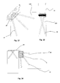
Figur 22 eine räumliche Struktur, die durch Verbindungselemente und Bauteile ausgeführt ist. - Ein Verbindungselement 1 besteht aus einem Körper. Dieser Körper umfasst eine Hülle 2 und enthält Füllmaterial 3 innerhalb der Hülle. Das Verbindungselement 1 ist derart ausgebildet, dass es ein durchgehendes Verankerungselement 10 aufnehmen kann.
- Das Verbindungselement wird auf der Außenfläche des Bauteils , dieser gegenüberliegend, befestigt. Dieses durchgehende Verankerungselement 10 kann zum Beispiel eine Schraube sein. Das Verankerungselement 10 durchquert mindestens zwei Wände 2a,2b. Auf diese Art und Weise gibt die Hülle 2 der Verbindung Starrheit, während das Füllmaterial 3 der Verbindung eine elastische Festigkeit verleiht. Das Füllmaterial 3 erlaubt die Befestigung des Verankerungselementes 10 längs des gesamten Durchgangbereiches innerhalb des Verbindungselementes 1. Das Verbindungselement 10 wird ins Bauteil 100 eingebracht, das zum Beispiel eine Holztafel sein kann. Auf vorteilhafter Art und Weise sind das Verankerungselement oder die Verankerungselemente derart geneigt eingebracht, dass eine bessere Befestigung gewährleistet wird. Das Verankerungselement kann im erfindungsgemäßen Verbindungselement 1 in bereitgestellten Bohrungen eingebracht sein oder kann zum Beispiel es selbst di Bohrung ausführen. Die Bohrung, wo das Verankerungselement 10 eingebracht ist, kann zum Beispiel auch ein Gewinde aufweisen.
- In einer weiteren Ausführungsform kann die Hülle leer sein und nur nach der Befestigung des Verankerungselementes oder der Verankerungselemente sowohl im Verbindungselement als auch in der Tafel 100 kann der Raum 3 beispielsweise mit einem Harz gefüllt werden.
- In einer anderen Ausführungsform wird der Raum 3 zum Beispiel mit Holz oder einem Holteil gefüllt.
- In einer weiteren Ausführungsform kann die Hülle leer sein und einen zweiten Körper beinhalten, der Lücken aufweist, die beispielsweise mit einem Harz nur nach der Befestigung des Verankerungselementes oder Verankerungselementen befüllt werden.
- In einer weiteren Ausführungsform kann die Hülle leer sein und einen Körper beinhalten, der Lücken aufweist, innerhalb dem Kapseln angeordnet sind, die durch Verankerungselemente durchbohrt und durchquert werden.
- Das Verbindungselement 1 kann Angriffstellen aufweisen, um eine einfachere Verstellung der Tafel 100 mit dem Verbindungselement 1 zu erlauben.
- In einer weiteren Ausführungsform können Angriffstellen vorgesehen sein, die mittels eines Verbindungselementes wie zum Beispiel einer poly-orthogonalen Platte, die Befestigung an weiteren Verbindungselementen derart erlaubt, dass auf sichere Art und Weise eine Reihe von Tafeln 100 und/oder Bauelemente verbunden werden können.
- Das Bauteil kann ein Holzbauteil und/oder eine Verbundteil aus mehren Schichten sein, das ein Mehrschichtteil, eine so genannte Sandwich Tafel bildet.
- Das erfindungsgemäße Verbindungselement 1 kann beispielsweise mit einem schon bestehenden Außenelement wie zum Beispiel einem Element verbunden werden, das in Fundamente aus Beton oder Stahlträgern angeordnet ist, die schon beim Bau anwesend sind.
- Das Verbindungselement kann auch zum Beispiel zwei Träger verbinden, wobei es auf dem Endteil des Trägers angeordnet ist. Auf diese Art und Weise kann das Verbindungselement eine Versenkverbindung ausführen, wobei darunter verstanden wird, dass keine Elemente vorhanden sein dürfen, die seitlich der Verbindung vorstehen. Dies erlaubt, dass die Beanspruchungen sich innerhalb des Schnittes des Trägers befinden. Auf diese Art und Weise können die Träger besser bemessen werden. Die Last ist überdies innerhalb des Schnittes der Träger angeordnet.
- Wie in
Figur 5 gezeigt, kann die Verbindung Träger-Träger ausgerichtet oder geneigt ausgeführt sein. In derFigur 5 ist ein Verbindungsmittel 20 vorhanden, das die beiden Verbindungselemente 1 verbindet, die mittels der Verankerungselemente 10 am Bauteil 100 befestigt sind. - In
Figur 6 und 7 ist ein Verbindungselement 1 dargestellt, das an einem Bauteil 100 befestigt ist. Das Verbindungselement 1 ist durch ein unten geschlossenes M gebildet und an ihm sind Verbindungsmittel 20 verbunden, insbesondere eine gebogene Platte, derart, dass sie sich an die Form des Verbindungselementes 1 anpasst. - Das Verbindungselement erlaubt überdies andere Bauteile leichter zu befestigen. Zum Beispiel eine Decke kann einfacher mit der Verbindung zwischen zwei Trägern verbunden werden.
- Das erfindungsgemäße Verbindungselement erlaubt überdies, die Verankerungselemente auf beliebige Art und Weise auszurichten, wobei dennoch eine optimale Befestigung sichergestellt ist.
- Das erfindungsgemäße Verbindungselement kann verwendet werden, um Holztafeln oder aus mehreren Holzschichten zusammengesetzte Tafeln, Träger, Holzträger oder andere Bauteile zu verbinden, wie zum Beispiel Betontafeln, Stahlbeton, Mehrschichttafeln, Polymertafeln.
- Das Verankerungselement 10 kann aus Holschrauben oder geharzten Stäben im Fall Verwendung des Verbindungselementes an Holzbauteilen oder dann aus Bewehrungsstäben bestehen, im Fall wo das Verbindungselement an Bauteilen aus bewehrten Beton verwendet wird.
- Um die Hülle auf einfache und schnelle Art und Weise herzustellen kann diese zum Beispiel über eine Extrusion ausgeführt werden. Vom so erhaltenen Extrusionsprofil kann das erfindungsgemäße Verbindungselement nach der geforderten Breite abgeschnitten werden.
- Die Hülle 2 kann auch durch Biegung eines Bleches zum Beispiel aus Metall gebildet werden.
-
Figur 8,9,10 und 11 sind Ausführungsformen des erfindungsgemäßen Verbindungselementes dargestellt. DieFigur 9 zeigt ein Verbindungselement 1, das an einer Tafel 100 über Verankerungselemente 10 befestigt ist. Die Hülle 2 ist M- förmig mit geschlossenem Boden gebildet. Das Füllmaterial füllt nicht vollständig die Hülle 2. Es sind beispielsweise Öffnungen 11 vorhanden. Diese Öffnungen können zum Beispiel dazu dienen, um Mittel für die Verstellung des Verbindungselementes 1 mit der Tafel 100 zu verstellen oder sie können einfach um Material zu sparen erhalten sein, können jedoch auch zum Beispiel für die Spanabführung dienen, wobei der Span während der Einführung des Verankerungselementes 10 oder während der Herstellung des Gewindes erzeugt wird. - In
Figur 12 und 13 ist ein Verbindungselement 1 dargestellt, das an Verbindungsmittel 20 über Befestigungselemente 21 befestigt ist. Diese Befestigungsmittel sind zum Beispiel ein Schraubbolzen, der beide Platten verschrauben kann, wobei nur innerhalb der Konstruktion die Bearbeitung möglich ist, wo somit eine Verbindung mit mechanischen Merkmalen von hoher Duktilität erhalten wird, da der Schraubbolzen 21 im mittigen Bereich gedreht und überdies es möglich ist, eventuelle Spiele zwischen Bohrung und Schraubbolzen zu beseitigen, wobei ein exzentrisches Rohr oder eine Harzkapsel verwendet werden können, die zwischen Schraubbolzen 21 und dem Füllmaterial 3 zwischengeschaltet ist. - Die
Figur 14 zeigt eine Verbindung zwischen einem Träger mit einem Verbindungselement, das auf einem Bauteil 100 befestigt ist, und einem zweiten Bauteil. - In einer weiteren bevorzugten Ausführungsform kann das Füllmaterial 3 Holz oder ein Pressholz sein.
-
Figur 11 zeigt eine andere Ausführungsform des erfindungsgemäßen Verbindungselementes 1. Das Element gemäß dieser Ausführungsform ist in zwei verschiedenen Kammern unterteilt, wobei in jeder Kammer Verankerungselemente 10 angeordnet sind. Zwischen den beiden Kammern ist eine Aufnahme für Verbindungsmittel 20 zwischengeschaltet. Diese Aufnahme für ein Verbindungsmittel 10 wird über Befestigungsmittel 21 befestigt, wobei auch die beiden Teile des Verbindungselementes verspannt werden. - In
Figur 17 und 18 ist eine weitere Ausführungsform dargestellt, mit der Aufnahme für die Verbindungsmittel 20, die in der Kammer des Verbindungselementes 1 angeordnet und durch Befestigungsmittel verspannt ist. - In der
Figur 19 und 20 ist ein Element gemäß denFiguren 17 und 18 mit einem Verbindungsmittel 20 gezeigt. Dieses Verbindungsmittel ist an der Aufnahme befestigt. Auf diese Art und Weise ist die Verbindung stabiler und sicherer. - In
Figur 21 ist eine Verbindung von zwei erfindungsgemäßen Verbindungselementen gezeigt, die miteinander über eine Platte und einer Reihe von Verankerungselemente 10 verbunden sind, die in nicht gezeigten Bauteilen befestigt sind. -
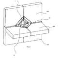
Figur 22 zeigt eine Raumstruktur die über das erfindungsgemäße Verbindungselement 1 ausgeführt ist, das eine Reihe von Bauteilen 100 verbindet, dessen Mitte eine Platte 20 ist. Aufstellung der Bezugsziffern. - 1
- Verbindungselement
- 2
- Hülle
- 2a
- oberer Teil der Hülle
- 2b
- unterer Teil der Hülle
- 3
- Füllmaterial
- 10
- Verankerungselemente
- 11
- Angriffsmittel
- 20
- Verbindungsmittel
- 21
- Befestigungsmittel
- 100
- Bauteile
Claims (14)
- Verbindungselement (1) von Bauteilen (100), dadurch gekennzeichnet, dass sie auf einer Außenfläche eines Bauteiles (100) gegenüberliegend angeordnet werden können, wobei das Verbindungselement (1) einen Körper aufweist, der eine Hülle (2) umfasst und mindestens ein Füllmaterial (3) innerhalb der Hülle (2) enthält, wo das Füllmaterial (3) elastischer ist als das Material, das die Hülle (2) bildet, wobei die Hülle (2) und das Füllmaterial (3) mindestens eine durchgehendes und im Bauteil (100) befestigbares Verankerungselement (10) aufnehmen.
- Verbindungselement nach Anspruch 1, dadurch gekennzeichnet, dass das Bauteil (100) aus Holz zusammengesetzt ist.
- Verbindungselement nach Anspruch 1 oder 2, dadurch gekennzeichnet, dass das Bauteil (100) mehrschichtig ist.
- Verbindungselement nach Anspruch 1,2 oder 3, dadurch gekennzeichnet, dass das Verankerungselement (10) mindestens zwei Mal die Hülle (2) durchquert.
- Verbindungselement nach Anspruch 1,2,3 oder 4, dadurch gekennzeichnet, dass das Verbindungselement mit mindestens einem zweiten Verbindungselement verbindbar ist.
- Verbindungselement nach einem der vorstehenden Ansprüche, dadurch gekennzeichnet, dass das Verbindungselement mindestens ein Angriffsmittel umfasst.
- Verbindungselement nach einem der vorstehenden Ansprüche, dadurch gekennzeichnet, dass die Hülle einen geschlossenen Umfang aufweist.
- Verbindungselement nach einem der vorstehenden Ansprüche, dadurch gekennzeichnet, dass das Füllmaterial mindestens eine Bohrung für die Verankerungselemente aufweist.
- Verbindungselement nach einem der vorstehenden Ansprüche, dadurch gekennzeichnet, dass das Füllmaterial mindestens eine Gewindebohrung für die Verankerungselemente aufweist.
- Verbindungselement nach einem der vorstehenden Ansprüche, dadurch gekennzeichnet, dass innerhalb der Hülle mindestens eine weitere Hülle angeordnet ist, die das Füllmaterial enthält.
- Verbindungselement nach einem der vorstehenden Ansprüche, dadurch gekennzeichnet, dass das Füllmaterial Aluminium ist.
- Verbindungselement nach einem der Ansprüche von 1 bis 10, dadurch gekennzeichnet, dass das Füllmaterial Harz ist.
- Verbindungselement nach einem der Ansprüche von 1 bis 10, dadurch gekennzeichnet, dass das Füllmaterial Holz oder ein Verbund auf der Basis von Holz ist.
- Verbindungselement nach einem der vorstehenden Ansprüche, dadurch gekennzeichnet, dass die Hülle mindestens zwei Füllmaterialien umfasst.
Priority Applications (1)
| Application Number | Priority Date | Filing Date | Title |
|---|---|---|---|
| PL13177095T PL2687645T3 (pl) | 2012-07-19 | 2013-07-18 | Element połączeniowy części, zwłaszcza paneli i wsporników |
Applications Claiming Priority (1)
| Application Number | Priority Date | Filing Date | Title |
|---|---|---|---|
| IT000028A ITBZ20120028A1 (it) | 2012-07-19 | 2012-07-19 | Un elemento per il collegamento di componenti di costruzione in particolare pannelli e travi |
Publications (2)
| Publication Number | Publication Date |
|---|---|
| EP2687645A1 true EP2687645A1 (de) | 2014-01-22 |
| EP2687645B1 EP2687645B1 (de) | 2016-11-23 |
Family
ID=46758830
Family Applications (1)
| Application Number | Title | Priority Date | Filing Date |
|---|---|---|---|
| EP13177095.0A Active EP2687645B1 (de) | 2012-07-19 | 2013-07-18 | Verbindungselement von Bauteilen, insbesondere Tafeln und Trägern |
Country Status (4)
| Country | Link |
|---|---|
| EP (1) | EP2687645B1 (de) |
| DK (1) | DK2687645T3 (de) |
| IT (1) | ITBZ20120028A1 (de) |
| PL (1) | PL2687645T3 (de) |
Cited By (1)
| Publication number | Priority date | Publication date | Assignee | Title |
|---|---|---|---|---|
| EP4464852A1 (de) | 2023-05-16 | 2024-11-20 | Hilti Aktiengesellschaft | Baustruktur aus holz |
Citations (3)
| Publication number | Priority date | Publication date | Assignee | Title |
|---|---|---|---|---|
| DE2150566A1 (de) | 1971-10-11 | 1973-04-19 | Dura Tufting Gmbh | Vorgefertigtes wandverkleidungselement fuer rauminnenflaechen und anordnung zu seiner montage |
| EP0442243A1 (de) | 1990-02-13 | 1991-08-21 | Lanz Oensingen Ag | Abhänge- und Montagevorrichtung |
| EP2243887A2 (de) | 2009-04-20 | 2010-10-27 | SWG Schraubenwerk Gaisbach GmbH | Beschlagelement |
-
2012
- 2012-07-19 IT IT000028A patent/ITBZ20120028A1/it unknown
-
2013
- 2013-07-18 DK DK13177095.0T patent/DK2687645T3/en active
- 2013-07-18 PL PL13177095T patent/PL2687645T3/pl unknown
- 2013-07-18 EP EP13177095.0A patent/EP2687645B1/de active Active
Patent Citations (3)
| Publication number | Priority date | Publication date | Assignee | Title |
|---|---|---|---|---|
| DE2150566A1 (de) | 1971-10-11 | 1973-04-19 | Dura Tufting Gmbh | Vorgefertigtes wandverkleidungselement fuer rauminnenflaechen und anordnung zu seiner montage |
| EP0442243A1 (de) | 1990-02-13 | 1991-08-21 | Lanz Oensingen Ag | Abhänge- und Montagevorrichtung |
| EP2243887A2 (de) | 2009-04-20 | 2010-10-27 | SWG Schraubenwerk Gaisbach GmbH | Beschlagelement |
Cited By (2)
| Publication number | Priority date | Publication date | Assignee | Title |
|---|---|---|---|---|
| EP4464852A1 (de) | 2023-05-16 | 2024-11-20 | Hilti Aktiengesellschaft | Baustruktur aus holz |
| WO2024235651A1 (en) | 2023-05-16 | 2024-11-21 | Hilti Aktiengesellschaft | Timber building structure |
Also Published As
| Publication number | Publication date |
|---|---|
| DK2687645T3 (en) | 2017-02-06 |
| PL2687645T3 (pl) | 2017-04-28 |
| ITBZ20120028A1 (it) | 2014-01-20 |
| EP2687645B1 (de) | 2016-11-23 |
Similar Documents
| Publication | Publication Date | Title |
|---|---|---|
| EP0263350B1 (de) | Verbinderkörper für den Holzbau | |
| CH672519A5 (de) | ||
| EP3384097A1 (de) | Verbindungsvorrichtung zum auflagern eines holzbauelements | |
| AT505266B1 (de) | Trägerelement, stegträgeranordnung und verfahren zu deren herstellung | |
| EP2060694A1 (de) | Gebäudewandelement | |
| EP2989263B1 (de) | Geschossdeckenkonstruktion und gebäude aus holz | |
| EP2439359A1 (de) | Verfahren zum Verstärken von betonierten Platten im Bereich von Stützelementen | |
| EP2037057B1 (de) | Schalungselemente für Decken nebst Verfahren | |
| EP2687645B1 (de) | Verbindungselement von Bauteilen, insbesondere Tafeln und Trägern | |
| DE19514685C2 (de) | Anordnung von mehreren Pfahlschuhen | |
| DE10066261B4 (de) | Verfahren zur Herstellung eines Wand-/Deckenbauhalbfertigteils | |
| EP3754125B1 (de) | Bauelement zum einbau in trennfugen von gebäuden | |
| DE102015002272B4 (de) | Hohlprofilverbindung zum Verlängern oder rechtwinkligen Verbinden von rechteckige Querschnitte aufweisenden Hohlprofilen | |
| EP0396136A1 (de) | Platte für Doppelböden | |
| DE102009022828A1 (de) | Fachwerkträger einschließlich eines unterspannten Trägers sowie ein zugehöriges Verfahren zur Herstellung | |
| EP3242983B1 (de) | Rahmentafelschalungselement | |
| EP1403441A1 (de) | Gebäudetrennwand in Holzbauweise | |
| EP1932978B1 (de) | Bewehrungselement für die Aufnahme von Kräften in betonierten Platten im Bereich von Stützelementen | |
| EP3315678B1 (de) | Fertigbauteil zum anschluss einer betonkragplatte an ein bauwerk | |
| AT516518B1 (de) | Armierte Stahlbetongleistragplatte | |
| DE20306942U1 (de) | System miteinander verbundener Bauelemente | |
| DE202006018112U1 (de) | Befestigungsvorrichtung für Signalmasten | |
| EP1428954A1 (de) | Leicht-Hochlochziegel | |
| EP3026199B1 (de) | Hohlwandanker | |
| EP1947248A1 (de) | Erdbebensichere konstruktion |
Legal Events
| Date | Code | Title | Description |
|---|---|---|---|
| PUAI | Public reference made under article 153(3) epc to a published international application that has entered the european phase |
Free format text: ORIGINAL CODE: 0009012 |
|
| AK | Designated contracting states |
Kind code of ref document: A1 Designated state(s): AL AT BE BG CH CY CZ DE DK EE ES FI FR GB GR HR HU IE IS IT LI LT LU LV MC MK MT NL NO PL PT RO RS SE SI SK SM TR |
|
| AX | Request for extension of the european patent |
Extension state: BA ME |
|
| 17P | Request for examination filed |
Effective date: 20140522 |
|
| RBV | Designated contracting states (corrected) |
Designated state(s): AL AT BE BG CH CY CZ DE DK EE ES FI FR GB GR HR HU IE IS IT LI LT LU LV MC MK MT NL NO PL PT RO RS SE SI SK SM TR |
|
| 17Q | First examination report despatched |
Effective date: 20160119 |
|
| REG | Reference to a national code |
Ref country code: DE Ref legal event code: R079 Ref document number: 502013005460 Country of ref document: DE Free format text: PREVIOUS MAIN CLASS: E04B0001610000 Ipc: E04B0001040000 |
|
| GRAP | Despatch of communication of intention to grant a patent |
Free format text: ORIGINAL CODE: EPIDOSNIGR1 |
|
| RIC1 | Information provided on ipc code assigned before grant |
Ipc: E04B 1/21 20060101ALI20160607BHEP Ipc: E04B 1/04 20060101AFI20160607BHEP Ipc: E04B 1/26 20060101ALI20160607BHEP Ipc: E04B 1/10 20060101ALI20160607BHEP |
|
| INTG | Intention to grant announced |
Effective date: 20160621 |
|
| GRAS | Grant fee paid |
Free format text: ORIGINAL CODE: EPIDOSNIGR3 |
|
| GRAA | (expected) grant |
Free format text: ORIGINAL CODE: 0009210 |
|
| AK | Designated contracting states |
Kind code of ref document: B1 Designated state(s): AL AT BE BG CH CY CZ DE DK EE ES FI FR GB GR HR HU IE IS IT LI LT LU LV MC MK MT NL NO PL PT RO RS SE SI SK SM TR |
|
| REG | Reference to a national code |
Ref country code: GB Ref legal event code: FG4D Free format text: NOT ENGLISH |
|
| RIN1 | Information on inventor provided before grant (corrected) |
Inventor name: POLASTRI, ANDREA Inventor name: ANGELI, ALBINO Inventor name: DAL RI, GIOVANNI |
|
| REG | Reference to a national code |
Ref country code: CH Ref legal event code: EP |
|
| REG | Reference to a national code |
Ref country code: IE Ref legal event code: FG4D Free format text: LANGUAGE OF EP DOCUMENT: GERMAN |
|
| REG | Reference to a national code |
Ref country code: AT Ref legal event code: REF Ref document number: 848066 Country of ref document: AT Kind code of ref document: T Effective date: 20161215 |
|
| REG | Reference to a national code |
Ref country code: DE Ref legal event code: R096 Ref document number: 502013005460 Country of ref document: DE |
|
| REG | Reference to a national code |
Ref country code: CH Ref legal event code: NV Representative=s name: KELLER AND PARTNER PATENTANWAELTE AG, CH |
|
| REG | Reference to a national code |
Ref country code: DK Ref legal event code: T3 Effective date: 20170131 |
|
| PG25 | Lapsed in a contracting state [announced via postgrant information from national office to epo] |
Ref country code: LV Free format text: LAPSE BECAUSE OF FAILURE TO SUBMIT A TRANSLATION OF THE DESCRIPTION OR TO PAY THE FEE WITHIN THE PRESCRIBED TIME-LIMIT Effective date: 20161123 |
|
| REG | Reference to a national code |
Ref country code: LT Ref legal event code: MG4D |
|
| REG | Reference to a national code |
Ref country code: NL Ref legal event code: MP Effective date: 20161123 |
|
| PG25 | Lapsed in a contracting state [announced via postgrant information from national office to epo] |
Ref country code: GR Free format text: LAPSE BECAUSE OF FAILURE TO SUBMIT A TRANSLATION OF THE DESCRIPTION OR TO PAY THE FEE WITHIN THE PRESCRIBED TIME-LIMIT Effective date: 20170224 Ref country code: LT Free format text: LAPSE BECAUSE OF FAILURE TO SUBMIT A TRANSLATION OF THE DESCRIPTION OR TO PAY THE FEE WITHIN THE PRESCRIBED TIME-LIMIT Effective date: 20161123 Ref country code: NL Free format text: LAPSE BECAUSE OF FAILURE TO SUBMIT A TRANSLATION OF THE DESCRIPTION OR TO PAY THE FEE WITHIN THE PRESCRIBED TIME-LIMIT Effective date: 20161123 Ref country code: SE Free format text: LAPSE BECAUSE OF FAILURE TO SUBMIT A TRANSLATION OF THE DESCRIPTION OR TO PAY THE FEE WITHIN THE PRESCRIBED TIME-LIMIT Effective date: 20161123 Ref country code: NO Free format text: LAPSE BECAUSE OF FAILURE TO SUBMIT A TRANSLATION OF THE DESCRIPTION OR TO PAY THE FEE WITHIN THE PRESCRIBED TIME-LIMIT Effective date: 20170223 |
|
| PG25 | Lapsed in a contracting state [announced via postgrant information from national office to epo] |
Ref country code: ES Free format text: LAPSE BECAUSE OF FAILURE TO SUBMIT A TRANSLATION OF THE DESCRIPTION OR TO PAY THE FEE WITHIN THE PRESCRIBED TIME-LIMIT Effective date: 20161123 Ref country code: PT Free format text: LAPSE BECAUSE OF FAILURE TO SUBMIT A TRANSLATION OF THE DESCRIPTION OR TO PAY THE FEE WITHIN THE PRESCRIBED TIME-LIMIT Effective date: 20170323 Ref country code: FI Free format text: LAPSE BECAUSE OF FAILURE TO SUBMIT A TRANSLATION OF THE DESCRIPTION OR TO PAY THE FEE WITHIN THE PRESCRIBED TIME-LIMIT Effective date: 20161123 Ref country code: HR Free format text: LAPSE BECAUSE OF FAILURE TO SUBMIT A TRANSLATION OF THE DESCRIPTION OR TO PAY THE FEE WITHIN THE PRESCRIBED TIME-LIMIT Effective date: 20161123 Ref country code: RS Free format text: LAPSE BECAUSE OF FAILURE TO SUBMIT A TRANSLATION OF THE DESCRIPTION OR TO PAY THE FEE WITHIN THE PRESCRIBED TIME-LIMIT Effective date: 20161123 |
|
| REG | Reference to a national code |
Ref country code: FR Ref legal event code: PLFP Year of fee payment: 5 |
|
| PG25 | Lapsed in a contracting state [announced via postgrant information from national office to epo] |
Ref country code: EE Free format text: LAPSE BECAUSE OF FAILURE TO SUBMIT A TRANSLATION OF THE DESCRIPTION OR TO PAY THE FEE WITHIN THE PRESCRIBED TIME-LIMIT Effective date: 20161123 Ref country code: CZ Free format text: LAPSE BECAUSE OF FAILURE TO SUBMIT A TRANSLATION OF THE DESCRIPTION OR TO PAY THE FEE WITHIN THE PRESCRIBED TIME-LIMIT Effective date: 20161123 Ref country code: RO Free format text: LAPSE BECAUSE OF FAILURE TO SUBMIT A TRANSLATION OF THE DESCRIPTION OR TO PAY THE FEE WITHIN THE PRESCRIBED TIME-LIMIT Effective date: 20161123 Ref country code: SK Free format text: LAPSE BECAUSE OF FAILURE TO SUBMIT A TRANSLATION OF THE DESCRIPTION OR TO PAY THE FEE WITHIN THE PRESCRIBED TIME-LIMIT Effective date: 20161123 |
|
| REG | Reference to a national code |
Ref country code: DE Ref legal event code: R097 Ref document number: 502013005460 Country of ref document: DE |
|
| PG25 | Lapsed in a contracting state [announced via postgrant information from national office to epo] |
Ref country code: SM Free format text: LAPSE BECAUSE OF FAILURE TO SUBMIT A TRANSLATION OF THE DESCRIPTION OR TO PAY THE FEE WITHIN THE PRESCRIBED TIME-LIMIT Effective date: 20161123 Ref country code: BG Free format text: LAPSE BECAUSE OF FAILURE TO SUBMIT A TRANSLATION OF THE DESCRIPTION OR TO PAY THE FEE WITHIN THE PRESCRIBED TIME-LIMIT Effective date: 20170223 |
|
| PLBE | No opposition filed within time limit |
Free format text: ORIGINAL CODE: 0009261 |
|
| STAA | Information on the status of an ep patent application or granted ep patent |
Free format text: STATUS: NO OPPOSITION FILED WITHIN TIME LIMIT |
|
| PGFP | Annual fee paid to national office [announced via postgrant information from national office to epo] |
Ref country code: GB Payment date: 20170831 Year of fee payment: 5 |
|
| 26N | No opposition filed |
Effective date: 20170824 |
|
| PG25 | Lapsed in a contracting state [announced via postgrant information from national office to epo] |
Ref country code: SI Free format text: LAPSE BECAUSE OF FAILURE TO SUBMIT A TRANSLATION OF THE DESCRIPTION OR TO PAY THE FEE WITHIN THE PRESCRIBED TIME-LIMIT Effective date: 20161123 |
|
| PGFP | Annual fee paid to national office [announced via postgrant information from national office to epo] |
Ref country code: IE Payment date: 20170928 Year of fee payment: 5 |
|
| REG | Reference to a national code |
Ref country code: BE Ref legal event code: MM Effective date: 20170731 |
|
| PG25 | Lapsed in a contracting state [announced via postgrant information from national office to epo] |
Ref country code: LU Free format text: LAPSE BECAUSE OF NON-PAYMENT OF DUE FEES Effective date: 20170718 |
|
| REG | Reference to a national code |
Ref country code: FR Ref legal event code: PLFP Year of fee payment: 6 |
|
| PG25 | Lapsed in a contracting state [announced via postgrant information from national office to epo] |
Ref country code: BE Free format text: LAPSE BECAUSE OF NON-PAYMENT OF DUE FEES Effective date: 20170731 |
|
| PG25 | Lapsed in a contracting state [announced via postgrant information from national office to epo] |
Ref country code: MT Free format text: LAPSE BECAUSE OF FAILURE TO SUBMIT A TRANSLATION OF THE DESCRIPTION OR TO PAY THE FEE WITHIN THE PRESCRIBED TIME-LIMIT Effective date: 20161123 |
|
| GBPC | Gb: european patent ceased through non-payment of renewal fee |
Effective date: 20180718 |
|
| REG | Reference to a national code |
Ref country code: IE Ref legal event code: MM4A |
|
| PG25 | Lapsed in a contracting state [announced via postgrant information from national office to epo] |
Ref country code: GB Free format text: LAPSE BECAUSE OF NON-PAYMENT OF DUE FEES Effective date: 20180718 Ref country code: IE Free format text: LAPSE BECAUSE OF NON-PAYMENT OF DUE FEES Effective date: 20180718 |
|
| PG25 | Lapsed in a contracting state [announced via postgrant information from national office to epo] |
Ref country code: MC Free format text: LAPSE BECAUSE OF FAILURE TO SUBMIT A TRANSLATION OF THE DESCRIPTION OR TO PAY THE FEE WITHIN THE PRESCRIBED TIME-LIMIT Effective date: 20161123 Ref country code: HU Free format text: LAPSE BECAUSE OF FAILURE TO SUBMIT A TRANSLATION OF THE DESCRIPTION OR TO PAY THE FEE WITHIN THE PRESCRIBED TIME-LIMIT; INVALID AB INITIO Effective date: 20130718 |
|
| PG25 | Lapsed in a contracting state [announced via postgrant information from national office to epo] |
Ref country code: CY Free format text: LAPSE BECAUSE OF NON-PAYMENT OF DUE FEES Effective date: 20161123 |
|
| PGFP | Annual fee paid to national office [announced via postgrant information from national office to epo] |
Ref country code: DK Payment date: 20190723 Year of fee payment: 7 Ref country code: FR Payment date: 20190725 Year of fee payment: 7 |
|
| PG25 | Lapsed in a contracting state [announced via postgrant information from national office to epo] |
Ref country code: MK Free format text: LAPSE BECAUSE OF FAILURE TO SUBMIT A TRANSLATION OF THE DESCRIPTION OR TO PAY THE FEE WITHIN THE PRESCRIBED TIME-LIMIT Effective date: 20161123 |
|
| PGFP | Annual fee paid to national office [announced via postgrant information from national office to epo] |
Ref country code: AT Payment date: 20190722 Year of fee payment: 7 |
|
| PGFP | Annual fee paid to national office [announced via postgrant information from national office to epo] |
Ref country code: CH Payment date: 20190725 Year of fee payment: 7 |
|
| PG25 | Lapsed in a contracting state [announced via postgrant information from national office to epo] |
Ref country code: TR Free format text: LAPSE BECAUSE OF FAILURE TO SUBMIT A TRANSLATION OF THE DESCRIPTION OR TO PAY THE FEE WITHIN THE PRESCRIBED TIME-LIMIT Effective date: 20161123 |
|
| PG25 | Lapsed in a contracting state [announced via postgrant information from national office to epo] |
Ref country code: AL Free format text: LAPSE BECAUSE OF FAILURE TO SUBMIT A TRANSLATION OF THE DESCRIPTION OR TO PAY THE FEE WITHIN THE PRESCRIBED TIME-LIMIT Effective date: 20161123 Ref country code: IS Free format text: LAPSE BECAUSE OF FAILURE TO SUBMIT A TRANSLATION OF THE DESCRIPTION OR TO PAY THE FEE WITHIN THE PRESCRIBED TIME-LIMIT Effective date: 20170323 |
|
| REG | Reference to a national code |
Ref country code: CH Ref legal event code: PFA Owner name: ROTHO BLAAS SRL GMBH, IT Free format text: FORMER OWNER: ROTHO BLAAS SRL GMBH, IT |
|
| REG | Reference to a national code |
Ref country code: CH Ref legal event code: PL |
|
| REG | Reference to a national code |
Ref country code: DK Ref legal event code: EBP Effective date: 20200731 |
|
| REG | Reference to a national code |
Ref country code: AT Ref legal event code: MM01 Ref document number: 848066 Country of ref document: AT Kind code of ref document: T Effective date: 20200718 |
|
| PG25 | Lapsed in a contracting state [announced via postgrant information from national office to epo] |
Ref country code: CH Free format text: LAPSE BECAUSE OF NON-PAYMENT OF DUE FEES Effective date: 20200731 Ref country code: LI Free format text: LAPSE BECAUSE OF NON-PAYMENT OF DUE FEES Effective date: 20200731 Ref country code: FR Free format text: LAPSE BECAUSE OF NON-PAYMENT OF DUE FEES Effective date: 20200731 |
|
| PG25 | Lapsed in a contracting state [announced via postgrant information from national office to epo] |
Ref country code: AT Free format text: LAPSE BECAUSE OF NON-PAYMENT OF DUE FEES Effective date: 20200718 |
|
| PG25 | Lapsed in a contracting state [announced via postgrant information from national office to epo] |
Ref country code: DK Free format text: LAPSE BECAUSE OF NON-PAYMENT OF DUE FEES Effective date: 20200731 |
|
| P01 | Opt-out of the competence of the unified patent court (upc) registered |
Effective date: 20230519 |
|
| REG | Reference to a national code |
Ref country code: DE Ref legal event code: R082 Ref document number: 502013005460 Country of ref document: DE Representative=s name: KANDLBINDER, MARKUS, DIPL.-PHYS., DE |
|
| PGFP | Annual fee paid to national office [announced via postgrant information from national office to epo] |
Ref country code: DE Payment date: 20240729 Year of fee payment: 12 |
|
| PGFP | Annual fee paid to national office [announced via postgrant information from national office to epo] |
Ref country code: PL Payment date: 20240702 Year of fee payment: 12 |
|
| PGFP | Annual fee paid to national office [announced via postgrant information from national office to epo] |
Ref country code: IT Payment date: 20240722 Year of fee payment: 12 |
|
| REG | Reference to a national code |
Ref country code: DE Ref legal event code: R119 Ref document number: 502013005460 Country of ref document: DE |
|
| PG25 | Lapsed in a contracting state [announced via postgrant information from national office to epo] |
Ref country code: DE Free format text: LAPSE BECAUSE OF NON-PAYMENT OF DUE FEES Effective date: 20260203 |