EP2687391A2 - Luftfederventil - Google Patents
Luftfederventil Download PDFInfo
- Publication number
- EP2687391A2 EP2687391A2 EP13002986.1A EP13002986A EP2687391A2 EP 2687391 A2 EP2687391 A2 EP 2687391A2 EP 13002986 A EP13002986 A EP 13002986A EP 2687391 A2 EP2687391 A2 EP 2687391A2
- Authority
- EP
- European Patent Office
- Prior art keywords
- limiting module
- valve
- compressed air
- air
- height
- Prior art date
- Legal status (The legal status is an assumption and is not a legal conclusion. Google has not performed a legal analysis and makes no representation as to the accuracy of the status listed.)
- Granted
Links
Images


Classifications
-
- B—PERFORMING OPERATIONS; TRANSPORTING
- B60—VEHICLES IN GENERAL
- B60G—VEHICLE SUSPENSION ARRANGEMENTS
- B60G17/00—Resilient suspensions having means for adjusting the spring or vibration-damper characteristics, for regulating the distance between a supporting surface and a sprung part of vehicle or for locking suspension during use to meet varying vehicular or surface conditions, e.g. due to speed or load
- B60G17/02—Spring characteristics, e.g. mechanical springs and mechanical adjusting means
- B60G17/04—Spring characteristics, e.g. mechanical springs and mechanical adjusting means fluid spring characteristics
- B60G17/052—Pneumatic spring characteristics
- B60G17/0523—Regulating distributors or valves for pneumatic springs
- B60G17/0525—Height adjusting or levelling valves
-
- B—PERFORMING OPERATIONS; TRANSPORTING
- B60—VEHICLES IN GENERAL
- B60G—VEHICLE SUSPENSION ARRANGEMENTS
- B60G2206/00—Indexing codes related to the manufacturing of suspensions: constructional features, the materials used, procedures or tools
- B60G2206/01—Constructional features of suspension elements, e.g. arms, dampers, springs
- B60G2206/011—Modular constructions
-
- B—PERFORMING OPERATIONS; TRANSPORTING
- B60—VEHICLES IN GENERAL
- B60G—VEHICLE SUSPENSION ARRANGEMENTS
- B60G2500/00—Indexing codes relating to the regulated action or device
- B60G2500/20—Spring action or springs
- B60G2500/202—Height or leveling valve for air-springs
- B60G2500/2021—Arrangement of valves
-
- B—PERFORMING OPERATIONS; TRANSPORTING
- B60—VEHICLES IN GENERAL
- B60G—VEHICLE SUSPENSION ARRANGEMENTS
- B60G2500/00—Indexing codes relating to the regulated action or device
- B60G2500/30—Height or ground clearance
Definitions
- the invention relates to an air spring valve for the controlled supply of compressed air to air springs, according to the preamble of claim 1.
- the invention also relates to a pneumatic suspension system and a vehicle with pneumatic suspension system.
- Air suspension valves in vehicles with pneumatic suspension control the supply of compressed air from a supply to air springs of the vehicle.
- the air springs are also referred to as bellows or are designed as bellows.
- the spring characteristic and / or the vehicle height can be influenced.
- air spring valves an automatic tracking of the air pressure in the bellows to adapt to increasing or decreasing load is possible. Without regulation, the vehicle would sag during loading as the bellows can not support the increased load.
- the air spring valve always supplies the bellows with sufficient compressed air so that the vehicle height remains constant during loading. Conversely, lifting the same is prevented by the function of the air suspension valve when unloading the vehicle.
- the air suspension valve is associated with a manually operable lifting / lowering valve with which an operator can increase or decrease the pressure in the bellows and so can change the vehicle height.
- the air spring valve may be provided with a height limiting module. This contains an additional valve, which passes from a defined upper vehicle height in a lock function or ventilation function, a line from Stops supply to the raising / lowering valve or vented the line, thus preventing further lifting by the operator.
- Fig. 1 and 2 refer to a prior art Heilfederventil 10 with integrated height limiting module 11 and associated lifting / lowering valve. The latter is hereinafter referred to only as a lift valve 12.
- a T-piece 14 is connected to an upper end of a valve housing 13. This is fed via a line 15 from a compressed air reservoir 16 and distributes the compressed air on the one hand via a line 17 to a terminal 18 on the height limiting module 11 and on the other hand via a port 19 directly into the valve housing 13th
- an extension not shown, is provided for the valve body, which performs movements corresponding to the valve body and thereby connects the connection 18 with a second connection 28 on the height limiting module 11, depending on the valve body position. From the connection 28, a line 29 via the lift valve 12 leads indirectly to the bellows 26, 27th
- a vent may also result, for example via a vent opening 30 on the height-limiting module 11.
- the venting causes compressed air to flow off the connections 20, 21 and the pressure in the bellows 26, 27 to decrease.
- the position of the valve body is controlled by pivoting a lever 31 externally mounted on the valve housing 13. This is unilaterally connected to a part of the vehicle, which can move up and down relative to the air suspension valve 10 depending on the load and driving dynamics.
- the air spring valve 10 is constructed so that, depending on the requirements, a version with or without height limiting module 11 can be built.
- the height limiting module 11 of the T-piece 14 is flanged opposite to the valve housing 13.
- an L-piece may be provided instead of the T-piece 14, since the line 17 is omitted.
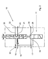
- Fig. 2 shows the circuit diagram of the air spring valve 10 according to the prior art with height limiting module 11. Shown is a central position of the valve body, in which the pressure in the lines is kept constant and no compressed air flows to or from. Depending on the position of the lever 31, the valve body moves in one of the other positions shown. The compressed air can flow in two stages into the lines 22, 23 or vent two stages. At the same time, the ventilation is limited by the function of the height limiting module eleventh
- Fig. 2 shown is a position of the height limiting module 11, in which the full pressure from the supply 16 is present in the line 29.
- a check valve 32 is provided in line 15 in line 15 in line 15 in line 15 in line 15 in line 15 in line 15 in line 15 in line 15 in line 15 in line 15 in line 15 in line 15 in line 15 in line 15 in line 15 in line 15 in line 15 in line 15 in line 15 in line 15 in line 15 in line 15 in line 15, a check valve 32 is provided.
- a disadvantage of the embodiment shown is the additional expense for the T-piece 14.
- the already mentioned L-piece is provided instead of the T-piece, so that there is no cost reduction in this embodiment.
- An air spring valve with T-piece and L-piece is also the DE 10 2007 057 947 A1 removable.
- the valve is referred to there as a level control valve.
- Object of the present invention is to provide an air spring valve, which is cheaper to produce.
- the new air spring valve at the same time in the version without height limiting module not be more expensive than in the known design.
- the air spring valve according to the invention has the features of claim 1.
- Part of the air spring valve is a valve housing.
- a connection to the entry of compressed air in particular in the valve housing.
- a height limiting module which is provided with connections for the entry of compressed air and the outlet of the compressed air.
- a further connection for compressed air is provided at the height limiting module.
- the further connection to the height-limiting module is directly connected to the connection to the height-limiting module for the admission of the compressed air. It is an internal connection in the height limiting module, so that a forwarding to the connection to the entry of compressed air into the valve housing is possible. There was previously arranged the tee.
- connection to the height limiting module for the admission of compressed air to a leading to a compressed air supply line can be connected.
- the supply of compressed air from the supply now takes place primarily to the height limiting module and no longer primarily to the T-piece at the opposite end of the height limiting module of the valve housing.
- the invention is also a pneumatic suspension system with at least one air spring valve according to the invention.
- the pneumatic suspension system may be part of a vehicle, in particular a motor vehicle, such as a towing vehicle in a truck.
- the pneumatic suspension system can also be part of a trailer vehicle without its own drive.
- the line 17 closes in Fig. 3 directly to the terminal 19 at the upper end of the air spring valve 33 at. A tee is not provided here. Therefore, the compressed air supply 16 is connected via a line 34 to the terminal 18 of a height limiting module 35.
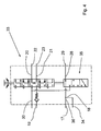
- Fig. 3 At the terminal 28 of the height limiting module 35 according to Fig. 3 is like in Fig. 1 connected to the lift valve 12 leading line 29. In Fig. 3 additionally provided is a further connection 36 on the height limiting module 35 for connection The line 17. Connections 18 and 36 are connected directly to each other inside the height limiting module 35, so that approximately the same pressure is applied in the line 17 as in line 34. Terminal 28 is connected to the terminal 18 only in accordance with the function of the height limiting module 35 , The height limiting module 35 is in both cases ( Fig. 1 and Fig. 3 ) designed as a 3/2-way valve. Upon movement of the valve body in the air spring valve 33 (or 10), starting from the position according to the Fig. 2 and 4 , closes the height limiting module 35, 11 first and goes on further movement in a venting function.
- the air spring valve 33 according to the invention Fig. 3 is, apart from the height limiting module, in relation to the known air spring valve 10 according to Fig. 1 almost unchanged. Only the height limiting module 35 and the cable guides have been changed. In addition, the T-piece 14 on the air spring valve 33 according to Fig. 3 not provided. Installation and / or installation of the air spring valve 33 are easier because no T-piece has to be connected. The additional connection to the height-limiting module 35 increases the production costs in relation to the height-limiting module 11 only slightly. However, the costs for the production and installation of the T-piece are eliminated.
Landscapes
- Engineering & Computer Science (AREA)
- Mechanical Engineering (AREA)
- Vehicle Body Suspensions (AREA)
- Fluid-Damping Devices (AREA)
Abstract
Description
- Die Erfindung betrifft ein Luftfederventil für die gesteuerte Zufuhr von Druckluft zu Luftfedern, gemäß dem Oberbegriff des Anspruchs 1. Daneben betrifft die Erfindung auch ein pneumatisches Federungssystem und ein Fahrzeug mit pneumatischem Federungssystem.
- Luftfederventile in Fahrzeugen mit pneumatischer Federung steuern die Zufuhr von Druckluft aus einem Vorrat zu Luftfedern des Fahrzeugs. Die Luftfedern werden auch als Federbälge bezeichnet bzw. sind als Federbälge ausgeführt. Durch Änderung des Luftdrucks in den Federbälgen können die Federcharakteristik und/oder die Fahrzeughöhe beeinflusst werden. Mit Luftfederventilen ist ein automatisches Nachführen des Luftdrucks in den Federbälgen zur Anpassung an zunehmende oder abnehmende Beladung möglich. Ohne Regelung würde das Fahrzeug beim Beladen absacken, da die Federbälge die erhöhte Last nicht tragen können. Durch das Luftfederventil wird den Federbälgen stets so viel Druckluft zugeführt, dass die Fahrzeughöhe beim Beladen konstant bleibt. Umgekehrt wird durch die Funktion des Luftfederventils beim Entladen des Fahrzeugs ein Anheben desselben verhindert.
- Dem Luftfederventil ist ein manuell betätigbares Hebe-/Senkventil zugeordnet, mit dem eine Bedienungsperson den Druck in den Federbälgen erhöhen oder verringern und so die Fahrzeughöhe verändern kann.
- Das Luftfederventil kann mit einem Höhenbegrenzungsmodul versehen sein. Dieses enthält ein zusätzliches Ventil, welches ab einer definierten oberen Fahrzeughöhe in eine Sperrfunktion bzw. Entlüftungsfunktion übergeht, eine Leitung vom Vorrat zum Hebe-/Senkventil absperrt oder die Leitung entlüftet und so ein weiteres Anheben durch die Bedienungsperson verhindert.
- Die
Fig. 1 und2 beziehen sich auf ein zum Stand der Technik zählendes Luftfederventil 10 mit integriertem Höhenbegrenzungsmodul 11 und zugeordnetem Hebe-/Senkventil. Letzteres wird nachfolgend nur als Liftventil 12 bezeichnet. - Wie in der Draufsicht auf das Luftfederventil 10 gemäß
Fig. 1 erkennbar, ist an einem oberen Ende eines Ventilgehäuses 13 ein T-Stück 14 angeschlossen. Dieses wird über eine Leitung 15 aus einem Druckluftvorrat 16 gespeist und verteilt die Druckluft einerseits über eine Leitung 17 an einen Anschluss 18 am Höhenbegrenzungsmodul 11 und andererseits über einen Anschluss 19 unmittelbar in das Ventilgehäuse 13. - Je nach Stellung eines im Ventilgehäuse 13 angeordneten, nicht gezeigten Ventilkörpers wird die Druckluft über Anschlüsse 20, 21 und Leitungen 22, 23 zum Liftventil 12 und von dort über Leitungen 24, 25 zu Federbälgen 26, 27 eines Fahrzeugs geleitet oder abgesperrt.
- Im Höhenbegrenzungsmodul 11 ist ein nicht gezeigter Fortsatz für den Ventilkörper vorgesehen, welcher zum Ventilkörper korrespondierende Bewegungen ausführt und dabei den Anschluss 18 je nach Ventilkörperstellung mit einem zweiten Anschluss 28 am Höhenbegrenzungsmodul 11 verbindet. Vom Anschluss 28 führt eine Leitung 29 über das Liftventil 12 mittelbar zu den Federbälgen 26, 27.
- Je nach Stellung des Ventilkörpers kann sich auch eine Entlüftung ergeben, etwa über eine Entlüftungsöffnung 30 am Höhenbegrenzungsmodul 11. Die Entlüftung bewirkt, dass an den Anschlüssen 20, 21 anliegende Druckluft abströmt und der Druck in den Federbälgen 26, 27 nachlässt. Die Stellung des Ventilkörpers wird gesteuert durch Schwenken eines außen am Ventilgehäuse 13 gelagerten Hebels 31. Dieser ist einseitig mit einem Teil des Fahrzeugs verbunden, welcher sich relativ zum Luftfederventil 10 je nach Beladung und Fahrdynamik auf- und abbewegen kann.
- Das Luftfederventil 10 ist so aufgebaut, dass je nach Anforderung eine Ausführung mit oder ohne Höhenbegrenzungsmodul 11 gebaut werden kann. In der in
Fig. 1 gezeigten Version ist das Höhenbegrenzungsmodul 11 dem T-Stück 14 gegenüberliegend an das Ventilgehäuse 13 angeflanscht. In einer Ausführung ohne Höhenbegrenzungsmodul 11 kann anstelle des T-Stücks 14 ein L-Stück vorgesehen sein, da die Leitung 17 entfällt. -
Fig. 2 zeigt das Schaltzeichen des Luftfederventils 10 gemäß Stand der Technik mit Höhenbegrenzungsmodul 11. Gezeigt ist eine mittlere Position des Ventilkörpers, bei der der Druck in den Leitungen konstant gehalten wird und keine Druckluft zu- oder abströmt. Je nach Position des Hebels 31 bewegt sich der Ventilkörper in eine der weiteren gezeigten Positionen. Dabei kann die Druckluft zweistufig in die Leitungen 22, 23 strömen bzw. zweistufig entlüften. Zugleich ist die Belüftung begrenzt durch die Funktion des Höhenbegrenzungsmoduls 11. - Je nach Position des Hebels 31 ist auch das Höhenbegrenzungsmodul 11 wirksam und sperrt die Leitung 29 oder entlüftet diese sogar. In
Fig. 2 gezeigt ist eine Stellung des Höhenbegrenzungsmoduls 11, in der in der Leitung 29 der volle Druck aus dem Vorrat 16 anliegt. In der Leitung 15 ist ein Rückschlagventil 32 vorgesehen. - Nachteil der gezeigten Ausführung ist der zusätzliche Aufwand für das T-Stück 14. Bei einer Ausführung des Luftfederventils ohne das Höhenbegrenzungsmodul ist anstelle des T-Stücks das bereits genannte L-Stück vorgesehen, sodass sich auch bei dieser Ausführung keine Kostenreduzierung ergibt.
- Ein Luftfederventil mit T-Stück und L-Stück ist auch der
DE 10 2007 057 947 A1 entnehmbar. Das Ventil wird dort als Niveauregelventil bezeichnet. - Aufgabe der vorliegenden Erfindung ist die Schaffung eines Luftfederventils, welches kostengünstiger herstellbar ist. Vorzugsweise soll das neue Luftfederventil zugleich in der Ausführung ohne Höhenbegrenzungsmodul nicht aufwendiger sein als in der bekannten Ausführung.
- Zur Lösung der Aufgabe weist das erfindungsgemäße Luftfederventil die Merkmale des Anspruchs 1 auf. Bestandteil des Luftfederventils ist ein Ventilgehäuse. Vorgesehen ist ein Anschluss zum Eintritt der Druckluft insbesondere in das Ventilgehäuse. Mit letzterem verbunden ist ein Höhenbegrenzungsmodul, welches mit Anschlüssen zum Eintritt der Druckluft und zum Austritt der Druckluft versehen ist. Außerdem ist am Höhenbegrenzungsmodul ein weiterer Anschluss für Druckluft vorgesehen. Durch den weiteren Anschluss ist es möglich die Funktion des bisher vorgesehenen T-Stücks am oberen Ende des Ventilgehäuses an das andere Ende des Ventilgehäuses zu verlagern, nämlich zum Höhenbegrenzungsmodul. Das Luftfederventil in einer Ausführung ohne Höhenbegrenzungsmodul wird durch die Maßnahme nicht aufwendiger. Außerdem kann das T-Stück eingespart werden.
- Vorteilhafterweise ist der weitere Anschluss am Höhenbegrenzungsmodul unmittelbar verbunden mit dem Anschluss am Höhenbegrenzungsmodul zum Eintritt der Druckluft. Es handelt sich um eine interne Verbindung im Höhenbegrenzungsmodul, so dass eine Weiterleitung bis zum Anschluss zum Eintritt der Druckluft in das Ventilgehäuse möglich ist. Dort war bislang das T-Stück angeordnet.
- Nach einem weiteren Gedanken der Erfindung ist der Anschluss am Höhenbegrenzungsmodul zum Eintritt der Druckluft an eine zu einem Druckluft-Vorrat führende Leitung anschließbar. Somit erfolgt die Druckluftzufuhr aus dem Vorrat jetzt primär zum Höhenbegrenzungsmodul und nicht mehr primär zum T-Stück an dem dem Höhenbegrenzungsmodul gegenüberliegenden Ende des Ventilgehäuses.
- Gegenstand der Erfindung ist auch ein pneumatisches Federungssystem mit mindestens einem erfindungsgemäßen Luftfederventil. Das pneumatische Federungssystem kann Bestandteil eines Fahrzeugs sein, insbesondere eines Kraftfahrzeugs, etwa eines Zugfahrzeugs in einem Lastzug. Das pneumatische Federungssystem kann aber auch Bestandteil eines Anhängerfahrzeugs ohne eigenen Antrieb sein.
- Weitere Merkmale der Erfindung ergeben sich aus der Beschreibung im Übrigen und aus den Ansprüchen. Vorteilhafte Ausführungsformen der Erfindung werden nachfolgend anhand von Zeichnungen näher erläutert. Es zeigen:
- Fig. 1
- eine Außenansicht (Vorderansicht) eines zum Stand der Technik zählenden Luftfederventils, wie oben bereits erläutert,
- Fig. 2
- das Schaltzeichen des zum Stand der Technik zählenden Luftfederventils gemäß
Fig. 1 , - Fig. 3
- eine Außenansicht (Rückansicht) eines erfindungsgemäßen Luftfederventils mit Luftdruck-Vorrat und Federbälgen,
- Fig. 4
- das Schaltzeichen des erfindungsgemäßen Luftfederventils gemäß
Fig. 3 . - Ausgehend von den oben im Zusammenhang mit dem Stand der Technik erläuterten
Fig. 1 und2 wird Bezug gekommen aufFig. 3 . - Soweit die Darstellungen in den Fig. übereinstimmen, sind gleiche Bezugsziffern angegeben. Aufgrund der neuen Konfiguration ist ein erfindungsgemäßes Luftfederventil in
Fig. 3 mit der Ziffer 33 bezeichnet und im Gegensatz zuFig. 1 in einer Rückansicht abgebildet. - Die Leitung 17 schließt in
Fig. 3 unmittelbar an den Anschluss 19 am oberen Ende des Luftfederventils 33 an. Ein T-Stück ist hier nicht vorgesehen. Deshalb ist der Druckluft-Vorrat 16 über eine Leitung 34 mit dem Anschluss 18 eines Höhenbegrenzungsmoduls 35 verbunden. - Am Anschluss 28 des Höhenbegrenzungsmoduls 35 gemäß
Fig. 3 ist wie inFig. 1 die zum Liftventil 12 führende Leitung 29 angeschlossen. InFig. 3 zusätzlich vorgesehen ist ein weiterer Anschluss 36 am Höhenbegrenzungsmodul 35 zum Anschluss der Leitung 17. Anschlüsse 18 und 36 sind im Inneren des Höhenbegrenzungsmoduls 35 direkt miteinander verbunden, so dass in der Leitung 17 stets annähernd der gleiche Druck anliegt wie in Leitung 34. Anschluss 28 ist nur entsprechend der Funktion des Höhenbegrenzungsmoduls 35 mit dem Anschluss 18 verbunden. Das Höhenbegrenzungsmodul 35 ist in beiden Fällen (Fig. 1 undFig. 3 ) als 3/2-Wegeventil ausgebildet. Bei Bewegung des Ventilkörpers im Luftfederventil 33 (bzw. 10), ausgehend von der Position gemäß denFig. 2 und4 , schließt das Höhenbegrenzungsmodul 35, 11 zunächst und geht bei weiterer Bewegung in eine Entlüftungsfunktion über. - Das erfindungsgemäße Luftfederventil 33 gemäß
Fig. 3 ist, abgesehen vom Höhenbegrenzungsmodul, im Verhältnis zum bekannten Luftfederventil 10 gemäßFig. 1 nahezu unverändert geblieben. Verändert wurden nur das Höhenbegrenzungsmodul 35 und die Leitungsführungen. Außerdem ist das T-Stück 14 am Luftfederventil 33 gemäßFig. 3 nicht vorgesehen. Montage und/oder Einbau des Luftfederventils 33 sind einfacher, da kein T-Stück mehr verbunden werden muss. Der zusätzliche Anschluss am Höhenbegrenzungsmodul 35 erhöht die Produktionskosten im Verhältnis zum Höhenbegrenzungsmodul 11 nur gering. Die Kosten für die Herstellung und Montage des T-Stücks entfallen aber.
Claims (6)
- Luftfederventil (33) für die gesteuerte Zufuhr von Druckluft zu Luftfedern, mit einem Ventilgehäuse (13), einem Anschluss (19) zum Eintritt der Druckluft, einem mit dem Ventilgehäuse (13) verbundenen Höhenbegrenzungsmodul (35) und mit Anschlüssen (18, 28) am Höhenbegrenzungsmodul (35) zum Eintritt der Druckluft ins Höhenbegrenzungsmodul (35) und zum Austritt der Druckluft, gekennzeichnet durch einen weiteren Anschluss (36) am Höhenbegrenzungsmodul (35).
- Luftfederventil nach Anspruch 1, dadurch gekennzeichnet, dass der weitere Anschluss (36) am Höhenbegrenzungsmodul (35) unmittelbar verbunden ist mit dem Anschluss (18) am Höhenbegrenzungsmodul (35) zum Eintritt der Druckluft.
- Luftfederventil nach Anspruch 1 oder 2, dadurch gekennzeichnet, dass der weitere Anschluss (36) am Höhenbegrenzungsmodul (35) über eine Leitung (17) mit dem Anschluss (19) am Ventilgehäuse (13) zum Eintritt der Druckluft verbunden ist.
- Luftfederventil nach Anspruch 1 oder einem der weiteren Ansprüche, dadurch gekennzeichnet, dass der Anschluss (18) am Höhenbegrenzungsmodul (35) zum Eintritt der Druckluft an eine zu einem Druckluft-Vorrat (16) führende Leitung (34) anschließbar ist.
- Pneumatisches Federungssystem mit mindestens einem Luftfederventil (33) nach Anspruch 1 oder einem der weiteren Ansprüche.
- Fahrzeug mit einem pneumatischen Federungssystem nach Anspruch 5.
Applications Claiming Priority (1)
| Application Number | Priority Date | Filing Date | Title |
|---|---|---|---|
| DE102012014349.4A DE102012014349B4 (de) | 2012-07-19 | 2012-07-19 | Luftfederventil |
Publications (3)
| Publication Number | Publication Date |
|---|---|
| EP2687391A2 true EP2687391A2 (de) | 2014-01-22 |
| EP2687391A3 EP2687391A3 (de) | 2014-07-23 |
| EP2687391B1 EP2687391B1 (de) | 2019-08-07 |
Family
ID=48670322
Family Applications (1)
| Application Number | Title | Priority Date | Filing Date |
|---|---|---|---|
| EP13002986.1A Active EP2687391B1 (de) | 2012-07-19 | 2013-06-11 | Luftfederventil |
Country Status (2)
| Country | Link |
|---|---|
| EP (1) | EP2687391B1 (de) |
| DE (1) | DE102012014349B4 (de) |
Citations (1)
| Publication number | Priority date | Publication date | Assignee | Title |
|---|---|---|---|---|
| DE102007057947A1 (de) | 2007-12-01 | 2009-06-10 | Haldex Brake Products Gmbh | Pneumatisches Verbindungselement für Druckluftanlagen |
Family Cites Families (4)
| Publication number | Priority date | Publication date | Assignee | Title |
|---|---|---|---|---|
| DE3716436A1 (de) * | 1987-05-16 | 1988-12-01 | Graubremse Gmbh | Niveauregelventil mit hoehenbegrenzung |
| DE4329432C1 (de) * | 1993-09-01 | 1995-04-06 | Grau Gmbh | Niveauregelventil zum selbsttätigen Konstanthalten der Höhe des Fahrzeugaufbaus eines Nutzfahrzeuges |
| DE4416280C1 (de) * | 1994-05-07 | 1995-05-11 | Grau Gmbh | Niveauregelventil zum selbsttätigen Konstanthalten der Fahrzeughöhe eines Nutzfahrzeuges mit Luftfederung |
| DE19607619C1 (de) * | 1996-02-29 | 1997-07-31 | Grau Gmbh | Niveauregelventil zum selbsttätigen Konstanthalten der Fahrzeughöhe eines Nutzfahrzeuges mit Luftfederung |
-
2012
- 2012-07-19 DE DE102012014349.4A patent/DE102012014349B4/de not_active Expired - Fee Related
-
2013
- 2013-06-11 EP EP13002986.1A patent/EP2687391B1/de active Active
Patent Citations (1)
| Publication number | Priority date | Publication date | Assignee | Title |
|---|---|---|---|---|
| DE102007057947A1 (de) | 2007-12-01 | 2009-06-10 | Haldex Brake Products Gmbh | Pneumatisches Verbindungselement für Druckluftanlagen |
Also Published As
| Publication number | Publication date |
|---|---|
| EP2687391A3 (de) | 2014-07-23 |
| DE102012014349A1 (de) | 2014-01-23 |
| DE102012014349B4 (de) | 2020-12-31 |
| EP2687391B1 (de) | 2019-08-07 |
Similar Documents
| Publication | Publication Date | Title |
|---|---|---|
| EP2445736B1 (de) | Druckluftversorgungssystem für einen druckluftverbraucherkreis, insbesondere für ein luftfederungssystem | |
| DE102007008159B4 (de) | Luftfederungseinrichtung mit elektrisch betätigtem Sperrventil | |
| DE10245815C5 (de) | Druckluftsteuervorrichtung für eine elektronische Luftfederungsanlage für ein Fahrzeug | |
| EP2836406B1 (de) | Luftaufbereitungsanlage für die druckluftversorgung von nutzkraftfahrzeugen | |
| DE102007008156A1 (de) | Luftfederungseinrichtung mit ausschließlich druckmittelbetätigten Steuerventilen | |
| DE102011051505B4 (de) | Niveauregelventileinheit mit integriertem Verteiler | |
| EP2106937B1 (de) | Nutzfahrzeug mit einer Gasfederung, insbesondere Luftfederung und Gasfederungssystem | |
| EP1963118A2 (de) | Hydropneumatische achsfederung für fahrzeuge | |
| EP3724044B1 (de) | Pneumatische ventilanordnung für ein anhängefahrzeug | |
| DE102015115082B4 (de) | Ventileinheit für pneumatische Anwendungen sowie Luftfederungsanlage | |
| DE102010003463B4 (de) | Pneumatische Baueinheiten für Luftfederungsanlagen | |
| DE10107644B4 (de) | Hydropneumatische Federung für Fahrzeuge mit stark wechselnden Achslasten | |
| DE202004010530U1 (de) | Hydraulischer Schaltkreis | |
| EP2687391B1 (de) | Luftfederventil | |
| DE102012021862A1 (de) | Windleiteinrichtung | |
| DE102017107994A1 (de) | Kraftfahrzeug-Fahrgestell | |
| DE102011114179A1 (de) | Ventileinrichtung für eine Luftfederungseinrichtung eines Fahrzeugs zur Entkopplung von Luftfederbälgen verschiedener Fahrzeugseiten | |
| DE102008021648B4 (de) | Niveauregelanordnung eines Fahrzeugaufbaus luftgefederter Fahrzeuge | |
| DE102021116424B3 (de) | Aktives Fahrwerksystem für ein Kraftfahrzeug mit zwei Fahrzeugachsen | |
| DE102013100295A1 (de) | Luftfederanlage und Ventil für ein Fahrzeug | |
| EP2371644B1 (de) | Druckluftanlage | |
| EP4155592B1 (de) | Ventileinrichtung, sowie fahrzeug mit einer luftfederungseinrichtung | |
| EP3181417B1 (de) | Druckluftsystem mit druckluftbehälter zur druckluftspeicherung und zur druckluftverteilung | |
| DE202018106952U1 (de) | Verbessertes Saugventil für die Luftfederung von LKW-Kabinen | |
| EP2957441B1 (de) | Luftfederungseinrichtung zum heben und senken eines fahrzeugaufbaus |
Legal Events
| Date | Code | Title | Description |
|---|---|---|---|
| PUAI | Public reference made under article 153(3) epc to a published international application that has entered the european phase |
Free format text: ORIGINAL CODE: 0009012 |
|
| AK | Designated contracting states |
Kind code of ref document: A2 Designated state(s): AL AT BE BG CH CY CZ DE DK EE ES FI FR GB GR HR HU IE IS IT LI LT LU LV MC MK MT NL NO PL PT RO RS SE SI SK SM TR |
|
| AX | Request for extension of the european patent |
Extension state: BA ME |
|
| PUAL | Search report despatched |
Free format text: ORIGINAL CODE: 0009013 |
|
| AK | Designated contracting states |
Kind code of ref document: A3 Designated state(s): AL AT BE BG CH CY CZ DE DK EE ES FI FR GB GR HR HU IE IS IT LI LT LU LV MC MK MT NL NO PL PT RO RS SE SI SK SM TR |
|
| AX | Request for extension of the european patent |
Extension state: BA ME |
|
| RIC1 | Information provided on ipc code assigned before grant |
Ipc: B60G 17/052 20060101ALI20140616BHEP Ipc: B60G 17/056 20060101AFI20140616BHEP |
|
| 17P | Request for examination filed |
Effective date: 20150123 |
|
| RBV | Designated contracting states (corrected) |
Designated state(s): AL AT BE BG CH CY CZ DE DK EE ES FI FR GB GR HR HU IE IS IT LI LT LU LV MC MK MT NL NO PL PT RO RS SE SI SK SM TR |
|
| GRAP | Despatch of communication of intention to grant a patent |
Free format text: ORIGINAL CODE: EPIDOSNIGR1 |
|
| STAA | Information on the status of an ep patent application or granted ep patent |
Free format text: STATUS: GRANT OF PATENT IS INTENDED |
|
| INTG | Intention to grant announced |
Effective date: 20190426 |
|
| GRAS | Grant fee paid |
Free format text: ORIGINAL CODE: EPIDOSNIGR3 |
|
| GRAA | (expected) grant |
Free format text: ORIGINAL CODE: 0009210 |
|
| STAA | Information on the status of an ep patent application or granted ep patent |
Free format text: STATUS: THE PATENT HAS BEEN GRANTED |
|
| AK | Designated contracting states |
Kind code of ref document: B1 Designated state(s): AL AT BE BG CH CY CZ DE DK EE ES FI FR GB GR HR HU IE IS IT LI LT LU LV MC MK MT NL NO PL PT RO RS SE SI SK SM TR |
|
| REG | Reference to a national code |
Ref country code: GB Ref legal event code: FG4D Free format text: NOT ENGLISH |
|
| REG | Reference to a national code |
Ref country code: CH Ref legal event code: EP Ref country code: AT Ref legal event code: REF Ref document number: 1163277 Country of ref document: AT Kind code of ref document: T Effective date: 20190815 |
|
| REG | Reference to a national code |
Ref country code: DE Ref legal event code: R096 Ref document number: 502013013287 Country of ref document: DE |
|
| REG | Reference to a national code |
Ref country code: IE Ref legal event code: FG4D Free format text: LANGUAGE OF EP DOCUMENT: GERMAN |
|
| REG | Reference to a national code |
Ref country code: NL Ref legal event code: MP Effective date: 20190807 |
|
| REG | Reference to a national code |
Ref country code: LT Ref legal event code: MG4D |
|
| PG25 | Lapsed in a contracting state [announced via postgrant information from national office to epo] |
Ref country code: BG Free format text: LAPSE BECAUSE OF FAILURE TO SUBMIT A TRANSLATION OF THE DESCRIPTION OR TO PAY THE FEE WITHIN THE PRESCRIBED TIME-LIMIT Effective date: 20191107 Ref country code: NO Free format text: LAPSE BECAUSE OF FAILURE TO SUBMIT A TRANSLATION OF THE DESCRIPTION OR TO PAY THE FEE WITHIN THE PRESCRIBED TIME-LIMIT Effective date: 20191107 Ref country code: HR Free format text: LAPSE BECAUSE OF FAILURE TO SUBMIT A TRANSLATION OF THE DESCRIPTION OR TO PAY THE FEE WITHIN THE PRESCRIBED TIME-LIMIT Effective date: 20190807 Ref country code: NL Free format text: LAPSE BECAUSE OF FAILURE TO SUBMIT A TRANSLATION OF THE DESCRIPTION OR TO PAY THE FEE WITHIN THE PRESCRIBED TIME-LIMIT Effective date: 20190807 Ref country code: LT Free format text: LAPSE BECAUSE OF FAILURE TO SUBMIT A TRANSLATION OF THE DESCRIPTION OR TO PAY THE FEE WITHIN THE PRESCRIBED TIME-LIMIT Effective date: 20190807 Ref country code: FI Free format text: LAPSE BECAUSE OF FAILURE TO SUBMIT A TRANSLATION OF THE DESCRIPTION OR TO PAY THE FEE WITHIN THE PRESCRIBED TIME-LIMIT Effective date: 20190807 Ref country code: SE Free format text: LAPSE BECAUSE OF FAILURE TO SUBMIT A TRANSLATION OF THE DESCRIPTION OR TO PAY THE FEE WITHIN THE PRESCRIBED TIME-LIMIT Effective date: 20190807 Ref country code: PT Free format text: LAPSE BECAUSE OF FAILURE TO SUBMIT A TRANSLATION OF THE DESCRIPTION OR TO PAY THE FEE WITHIN THE PRESCRIBED TIME-LIMIT Effective date: 20191209 |
|
| PG25 | Lapsed in a contracting state [announced via postgrant information from national office to epo] |
Ref country code: AL Free format text: LAPSE BECAUSE OF FAILURE TO SUBMIT A TRANSLATION OF THE DESCRIPTION OR TO PAY THE FEE WITHIN THE PRESCRIBED TIME-LIMIT Effective date: 20190807 Ref country code: GR Free format text: LAPSE BECAUSE OF FAILURE TO SUBMIT A TRANSLATION OF THE DESCRIPTION OR TO PAY THE FEE WITHIN THE PRESCRIBED TIME-LIMIT Effective date: 20191108 Ref country code: IS Free format text: LAPSE BECAUSE OF FAILURE TO SUBMIT A TRANSLATION OF THE DESCRIPTION OR TO PAY THE FEE WITHIN THE PRESCRIBED TIME-LIMIT Effective date: 20191207 Ref country code: RS Free format text: LAPSE BECAUSE OF FAILURE TO SUBMIT A TRANSLATION OF THE DESCRIPTION OR TO PAY THE FEE WITHIN THE PRESCRIBED TIME-LIMIT Effective date: 20190807 Ref country code: LV Free format text: LAPSE BECAUSE OF FAILURE TO SUBMIT A TRANSLATION OF THE DESCRIPTION OR TO PAY THE FEE WITHIN THE PRESCRIBED TIME-LIMIT Effective date: 20190807 Ref country code: ES Free format text: LAPSE BECAUSE OF FAILURE TO SUBMIT A TRANSLATION OF THE DESCRIPTION OR TO PAY THE FEE WITHIN THE PRESCRIBED TIME-LIMIT Effective date: 20190807 |
|
| PG25 | Lapsed in a contracting state [announced via postgrant information from national office to epo] |
Ref country code: TR Free format text: LAPSE BECAUSE OF FAILURE TO SUBMIT A TRANSLATION OF THE DESCRIPTION OR TO PAY THE FEE WITHIN THE PRESCRIBED TIME-LIMIT Effective date: 20190807 |
|
| PG25 | Lapsed in a contracting state [announced via postgrant information from national office to epo] |
Ref country code: IT Free format text: LAPSE BECAUSE OF FAILURE TO SUBMIT A TRANSLATION OF THE DESCRIPTION OR TO PAY THE FEE WITHIN THE PRESCRIBED TIME-LIMIT Effective date: 20190807 Ref country code: RO Free format text: LAPSE BECAUSE OF FAILURE TO SUBMIT A TRANSLATION OF THE DESCRIPTION OR TO PAY THE FEE WITHIN THE PRESCRIBED TIME-LIMIT Effective date: 20190807 Ref country code: DK Free format text: LAPSE BECAUSE OF FAILURE TO SUBMIT A TRANSLATION OF THE DESCRIPTION OR TO PAY THE FEE WITHIN THE PRESCRIBED TIME-LIMIT Effective date: 20190807 Ref country code: PL Free format text: LAPSE BECAUSE OF FAILURE TO SUBMIT A TRANSLATION OF THE DESCRIPTION OR TO PAY THE FEE WITHIN THE PRESCRIBED TIME-LIMIT Effective date: 20190807 Ref country code: EE Free format text: LAPSE BECAUSE OF FAILURE TO SUBMIT A TRANSLATION OF THE DESCRIPTION OR TO PAY THE FEE WITHIN THE PRESCRIBED TIME-LIMIT Effective date: 20190807 |
|
| PG25 | Lapsed in a contracting state [announced via postgrant information from national office to epo] |
Ref country code: CZ Free format text: LAPSE BECAUSE OF FAILURE TO SUBMIT A TRANSLATION OF THE DESCRIPTION OR TO PAY THE FEE WITHIN THE PRESCRIBED TIME-LIMIT Effective date: 20190807 Ref country code: SK Free format text: LAPSE BECAUSE OF FAILURE TO SUBMIT A TRANSLATION OF THE DESCRIPTION OR TO PAY THE FEE WITHIN THE PRESCRIBED TIME-LIMIT Effective date: 20190807 Ref country code: IS Free format text: LAPSE BECAUSE OF FAILURE TO SUBMIT A TRANSLATION OF THE DESCRIPTION OR TO PAY THE FEE WITHIN THE PRESCRIBED TIME-LIMIT Effective date: 20200224 Ref country code: SM Free format text: LAPSE BECAUSE OF FAILURE TO SUBMIT A TRANSLATION OF THE DESCRIPTION OR TO PAY THE FEE WITHIN THE PRESCRIBED TIME-LIMIT Effective date: 20190807 |
|
| REG | Reference to a national code |
Ref country code: DE Ref legal event code: R097 Ref document number: 502013013287 Country of ref document: DE |
|
| PLBE | No opposition filed within time limit |
Free format text: ORIGINAL CODE: 0009261 |
|
| STAA | Information on the status of an ep patent application or granted ep patent |
Free format text: STATUS: NO OPPOSITION FILED WITHIN TIME LIMIT |
|
| PG2D | Information on lapse in contracting state deleted |
Ref country code: IS |
|
| 26N | No opposition filed |
Effective date: 20200603 |
|
| PG25 | Lapsed in a contracting state [announced via postgrant information from national office to epo] |
Ref country code: SI Free format text: LAPSE BECAUSE OF FAILURE TO SUBMIT A TRANSLATION OF THE DESCRIPTION OR TO PAY THE FEE WITHIN THE PRESCRIBED TIME-LIMIT Effective date: 20190807 |
|
| PG25 | Lapsed in a contracting state [announced via postgrant information from national office to epo] |
Ref country code: MC Free format text: LAPSE BECAUSE OF FAILURE TO SUBMIT A TRANSLATION OF THE DESCRIPTION OR TO PAY THE FEE WITHIN THE PRESCRIBED TIME-LIMIT Effective date: 20190807 |
|
| REG | Reference to a national code |
Ref country code: CH Ref legal event code: PL |
|
| REG | Reference to a national code |
Ref country code: DE Ref legal event code: R081 Ref document number: 502013013287 Country of ref document: DE Owner name: ZF CV SYSTEMS EUROPE BV, BE Free format text: FORMER OWNER: WABCO GMBH, 30453 HANNOVER, DE Ref country code: DE Ref legal event code: R081 Ref document number: 502013013287 Country of ref document: DE Owner name: ZF CV SYSTEMS HANNOVER GMBH, DE Free format text: FORMER OWNER: WABCO GMBH, 30453 HANNOVER, DE |
|
| PG25 | Lapsed in a contracting state [announced via postgrant information from national office to epo] |
Ref country code: LU Free format text: LAPSE BECAUSE OF NON-PAYMENT OF DUE FEES Effective date: 20200611 |
|
| REG | Reference to a national code |
Ref country code: BE Ref legal event code: MM Effective date: 20200630 |
|
| PG25 | Lapsed in a contracting state [announced via postgrant information from national office to epo] |
Ref country code: LI Free format text: LAPSE BECAUSE OF NON-PAYMENT OF DUE FEES Effective date: 20200630 Ref country code: IE Free format text: LAPSE BECAUSE OF NON-PAYMENT OF DUE FEES Effective date: 20200611 Ref country code: CH Free format text: LAPSE BECAUSE OF NON-PAYMENT OF DUE FEES Effective date: 20200630 |
|
| PG25 | Lapsed in a contracting state [announced via postgrant information from national office to epo] |
Ref country code: BE Free format text: LAPSE BECAUSE OF NON-PAYMENT OF DUE FEES Effective date: 20200630 |
|
| REG | Reference to a national code |
Ref country code: AT Ref legal event code: MM01 Ref document number: 1163277 Country of ref document: AT Kind code of ref document: T Effective date: 20200611 |
|
| PG25 | Lapsed in a contracting state [announced via postgrant information from national office to epo] |
Ref country code: AT Free format text: LAPSE BECAUSE OF NON-PAYMENT OF DUE FEES Effective date: 20200611 |
|
| REG | Reference to a national code |
Ref country code: DE Ref legal event code: R081 Ref document number: 502013013287 Country of ref document: DE Owner name: ZF CV SYSTEMS EUROPE BV, BE Free format text: FORMER OWNER: ZF CV SYSTEMS HANNOVER GMBH, 30453 HANNOVER, DE |
|
| PG25 | Lapsed in a contracting state [announced via postgrant information from national office to epo] |
Ref country code: MT Free format text: LAPSE BECAUSE OF FAILURE TO SUBMIT A TRANSLATION OF THE DESCRIPTION OR TO PAY THE FEE WITHIN THE PRESCRIBED TIME-LIMIT Effective date: 20190807 Ref country code: CY Free format text: LAPSE BECAUSE OF FAILURE TO SUBMIT A TRANSLATION OF THE DESCRIPTION OR TO PAY THE FEE WITHIN THE PRESCRIBED TIME-LIMIT Effective date: 20190807 |
|
| PG25 | Lapsed in a contracting state [announced via postgrant information from national office to epo] |
Ref country code: MK Free format text: LAPSE BECAUSE OF FAILURE TO SUBMIT A TRANSLATION OF THE DESCRIPTION OR TO PAY THE FEE WITHIN THE PRESCRIBED TIME-LIMIT Effective date: 20190807 |
|
| P01 | Opt-out of the competence of the unified patent court (upc) registered |
Effective date: 20230528 |
|
| PGFP | Annual fee paid to national office [announced via postgrant information from national office to epo] |
Ref country code: DE Payment date: 20250402 Year of fee payment: 13 |
|
| PGFP | Annual fee paid to national office [announced via postgrant information from national office to epo] |
Ref country code: GB Payment date: 20250401 Year of fee payment: 13 |
|
| PGFP | Annual fee paid to national office [announced via postgrant information from national office to epo] |
Ref country code: FR Payment date: 20250401 Year of fee payment: 13 |