EP2106937B1 - Nutzfahrzeug mit einer Gasfederung, insbesondere Luftfederung und Gasfederungssystem - Google Patents
Nutzfahrzeug mit einer Gasfederung, insbesondere Luftfederung und Gasfederungssystem Download PDFInfo
- Publication number
- EP2106937B1 EP2106937B1 EP09004772A EP09004772A EP2106937B1 EP 2106937 B1 EP2106937 B1 EP 2106937B1 EP 09004772 A EP09004772 A EP 09004772A EP 09004772 A EP09004772 A EP 09004772A EP 2106937 B1 EP2106937 B1 EP 2106937B1
- Authority
- EP
- European Patent Office
- Prior art keywords
- commercial vehicle
- level
- pressure
- bellows
- regulating valve
- Prior art date
- Legal status (The legal status is an assumption and is not a legal conclusion. Google has not performed a legal analysis and makes no representation as to the accuracy of the status listed.)
- Not-in-force
Links
Images
Classifications
-
- B—PERFORMING OPERATIONS; TRANSPORTING
- B60—VEHICLES IN GENERAL
- B60G—VEHICLE SUSPENSION ARRANGEMENTS
- B60G17/00—Resilient suspensions having means for adjusting the spring or vibration-damper characteristics, for regulating the distance between a supporting surface and a sprung part of vehicle or for locking suspension during use to meet varying vehicular or surface conditions, e.g. due to speed or load
- B60G17/02—Spring characteristics, e.g. mechanical springs and mechanical adjusting means
- B60G17/033—Spring characteristics, e.g. mechanical springs and mechanical adjusting means characterised by regulating means acting on more than one spring
-
- B—PERFORMING OPERATIONS; TRANSPORTING
- B60—VEHICLES IN GENERAL
- B60G—VEHICLE SUSPENSION ARRANGEMENTS
- B60G17/00—Resilient suspensions having means for adjusting the spring or vibration-damper characteristics, for regulating the distance between a supporting surface and a sprung part of vehicle or for locking suspension during use to meet varying vehicular or surface conditions, e.g. due to speed or load
- B60G17/02—Spring characteristics, e.g. mechanical springs and mechanical adjusting means
- B60G17/04—Spring characteristics, e.g. mechanical springs and mechanical adjusting means fluid spring characteristics
- B60G17/052—Pneumatic spring characteristics
- B60G17/0523—Regulating distributors or valves for pneumatic springs
- B60G17/0525—Height adjusting or levelling valves
-
- B—PERFORMING OPERATIONS; TRANSPORTING
- B60—VEHICLES IN GENERAL
- B60G—VEHICLE SUSPENSION ARRANGEMENTS
- B60G17/00—Resilient suspensions having means for adjusting the spring or vibration-damper characteristics, for regulating the distance between a supporting surface and a sprung part of vehicle or for locking suspension during use to meet varying vehicular or surface conditions, e.g. due to speed or load
- B60G17/02—Spring characteristics, e.g. mechanical springs and mechanical adjusting means
- B60G17/04—Spring characteristics, e.g. mechanical springs and mechanical adjusting means fluid spring characteristics
- B60G17/056—Regulating distributors or valves for hydropneumatic systems
- B60G17/0565—Height adjusting valves
-
- B—PERFORMING OPERATIONS; TRANSPORTING
- B60—VEHICLES IN GENERAL
- B60G—VEHICLE SUSPENSION ARRANGEMENTS
- B60G2202/00—Indexing codes relating to the type of spring, damper or actuator
- B60G2202/10—Type of spring
- B60G2202/15—Fluid spring
- B60G2202/152—Pneumatic spring
-
- B—PERFORMING OPERATIONS; TRANSPORTING
- B60—VEHICLES IN GENERAL
- B60G—VEHICLE SUSPENSION ARRANGEMENTS
- B60G2300/00—Indexing codes relating to the type of vehicle
- B60G2300/02—Trucks; Load vehicles
-
- B—PERFORMING OPERATIONS; TRANSPORTING
- B60—VEHICLES IN GENERAL
- B60G—VEHICLE SUSPENSION ARRANGEMENTS
- B60G2400/00—Indexing codes relating to detected, measured or calculated conditions or factors
- B60G2400/25—Stroke; Height; Displacement
- B60G2400/252—Stroke; Height; Displacement vertical
-
- B—PERFORMING OPERATIONS; TRANSPORTING
- B60—VEHICLES IN GENERAL
- B60G—VEHICLE SUSPENSION ARRANGEMENTS
- B60G2400/00—Indexing codes relating to detected, measured or calculated conditions or factors
- B60G2400/50—Pressure
- B60G2400/51—Pressure in suspension unit
- B60G2400/512—Pressure in suspension unit in spring
- B60G2400/5122—Fluid spring
- B60G2400/51222—Pneumatic
-
- B—PERFORMING OPERATIONS; TRANSPORTING
- B60—VEHICLES IN GENERAL
- B60G—VEHICLE SUSPENSION ARRANGEMENTS
- B60G2500/00—Indexing codes relating to the regulated action or device
- B60G2500/20—Spring action or springs
- B60G2500/202—Height or leveling valve for air-springs
-
- B—PERFORMING OPERATIONS; TRANSPORTING
- B60—VEHICLES IN GENERAL
- B60G—VEHICLE SUSPENSION ARRANGEMENTS
- B60G2500/00—Indexing codes relating to the regulated action or device
- B60G2500/20—Spring action or springs
- B60G2500/204—Pressure regulating valves for air-springs
-
- B—PERFORMING OPERATIONS; TRANSPORTING
- B60—VEHICLES IN GENERAL
- B60G—VEHICLE SUSPENSION ARRANGEMENTS
- B60G2500/00—Indexing codes relating to the regulated action or device
- B60G2500/30—Height or ground clearance
-
- B—PERFORMING OPERATIONS; TRANSPORTING
- B60—VEHICLES IN GENERAL
- B60G—VEHICLE SUSPENSION ARRANGEMENTS
- B60G2600/00—Indexing codes relating to particular elements, systems or processes used on suspension systems or suspension control systems
- B60G2600/18—Automatic control means
-
- B—PERFORMING OPERATIONS; TRANSPORTING
- B60—VEHICLES IN GENERAL
- B60G—VEHICLE SUSPENSION ARRANGEMENTS
- B60G2600/00—Indexing codes relating to particular elements, systems or processes used on suspension systems or suspension control systems
- B60G2600/20—Manual control or setting means
-
- B—PERFORMING OPERATIONS; TRANSPORTING
- B60—VEHICLES IN GENERAL
- B60G—VEHICLE SUSPENSION ARRANGEMENTS
- B60G2800/00—Indexing codes relating to the type of movement or to the condition of the vehicle and to the end result to be achieved by the control action
- B60G2800/20—Stationary vehicle
- B60G2800/203—Stationary vehicle lowering the floor for loading/unloading
-
- B—PERFORMING OPERATIONS; TRANSPORTING
- B60—VEHICLES IN GENERAL
- B60G—VEHICLE SUSPENSION ARRANGEMENTS
- B60G2800/00—Indexing codes relating to the type of movement or to the condition of the vehicle and to the end result to be achieved by the control action
- B60G2800/90—System Controller type
- B60G2800/91—Suspension Control
- B60G2800/914—Height Control System
Definitions
- the invention relates to a commercial vehicle with a gas suspension, in particular air suspension, according to the preamble of claim 1. Furthermore, the invention relates to a gas suspension system for a commercial vehicle.
- a commercial vehicle of the type mentioned is from the DE 10 2004 051 740 B4 known.
- a maximum clear loading space height is sought.
- the legally prescribed, maximum vehicle height in the loaded state when the tires of the commercial vehicle have a lower radius than in the unloaded state, should not be exceeded.
- unloading however, there is the problem that the statutory maximum vehicle height is exceeded by relieving the tires.
- a method for changing the driving level in a commercial vehicle with an electronically controlled level control valve describes, for example DE 10 2004 051 740 B4 , Therein, a control valve is disclosed, which is connected to the bellows of an air suspension system. The control valve is further connected to a control device which regulates the time of opening and closing of the valve. The control device receives data that provide information about the current ride height of the commercial vehicle. The data is captured by sensors that measure the actual level of the vehicle based on the distance from the vehicle Determine vehicle frame to the vehicle axle, the shock absorber hardness, the axle loads or the pressurization of the bellows.
- the invention has for its object to provide a commercial vehicle with a gas suspension, in particular air suspension, whose ride height is adjustable depending on the loading condition, the utility vehicle, in particular the corresponding device for driving height adjustment, is easy and inexpensive to produce.
- the invention is based on the idea to provide a commercial vehicle with a gas suspension, in particular air suspension, comprising one or more bellows arranged between an axle and a vehicle frame, wherein the bellows are coupled to at least one level control valve such that the ride height of the utility vehicle is variable ,
- the level control valve on a control pressure input which is connected directly to at least one bellows in such a way that the ride height of the commercial vehicle in response to the pressure within at least one Federbalgs is variable.
- the direct coupling of the control pressure input with at least one bellows allows the pressure within the bellows can be used directly to control the ride height.
- a complex, electronic implementation or regulation is not necessary.
- This also eliminates a relatively extensive wiring, since the level control valve according to the invention is purely mechanically actuated and requires no electrical power supply for operation.
- the commercial vehicle according to the invention in particular the gas suspension of the commercial vehicle according to the invention, generally has a relatively simple structure, so that a simple, fast and cost-effective production and assembly is ensured.
- the level control valve is coupled to a gas supply such that the supply of a supply pressure to at least one bellows in direct dependence of a control pressure is controllable, wherein the control pressure corresponds to the pressure within the Federbalgs.
- the level control valve is connected between a gas supply, for example a compressed air tank, and at least one bellows of the gas suspension.
- the pressure in the bellows serves as a control pressure, in dependence of which the level control valve can be actuated.
- the level control valve opens or blocks the connection between the gas supply and the bellows.
- the level control valve connects the at least one bellows with the environment, so that when opening the level control valve gas, especially air, escapes from the bellows.
- the level control valve is preferably with a control pressure of at most three bar, in particular at most 2.5 bar, in particular at most 2 bar, in particular at most 1.5 bar, operable. This relatively low control pressure ensures that the level control valve is controlled directly by the pressure inside the bellows. An adaptation of the pressure fed to the level control bellows pressure for use as a control pressure, for example by a device for pressure increase, is not necessary.
- the level control valve may be adjustable for operation with different switching pressures.
- the switching pressure the control pressure value which causes the actuation of the level control valve is described, that is, the control pressure value. where the valve opens or closes.
- the level control valve can thus be universally installed in various commercial vehicle types.
- the valve is adapted and adjusted to the characteristics of the respective vehicle type, so that the switching pressure corresponds to the control pressure at which the commercial vehicle has the statutory driving height.
- the level control valve can be used for use in semi-trailers, flatbed vehicles, dump trucks or curtainsider semi-trailers.
- the invention is not limited to that the level control valve is adapted to comply with the statutory maximum height of a commercial vehicle. Much more Any ride height can be set, which is maintained by means of the valve. However, the adjustment of the valve to the statutory maximum height is preferred in order to provide a maximum loading height in the interior of the commercial vehicle.
- the level control valve is adapted such that the ride height by at most 35 mm, in particular at most 30 mm, in particular at most 25 mm, in particular at most 20 mm, is variable.
- the loading of a commercial vehicle causes a deformation of the tires, so that the static radius of the tires is reduced with increasing load. During unloading, the tires regain their original shape.
- the change in the static radius of the tires leads to a change in ride height of the commercial vehicle of up to 25 mm to 35 mm.
- the level control valve is therefore adapted to compensate for the change in ride height or compensate. The fact that the level control valve just compensates for the change in height between loaded and unloaded state of the commercial vehicle, the efficiency and life of the valve is increased.
- a plurality of bellows are connected to a common level control valve.
- a control of the ride height is equally possible because the pressure within the bellows is changed simultaneously.
- the construction of the gas suspension with a small number of level control valves is simple and inexpensive.
- the level control valve may include a mechanical directional control valve. Such a valve has a particularly simple structure and high reliability.
- the directional control valve has at least two, in particular three, switching positions for setting at least two, in particular three, driving heights.
- the level control valve is adapted such that the ride height of the commercial vehicle is additionally externally adjustable.
- the ride height can be adjusted to a desired level, for example by a user, in particular the driver of the utility vehicle.
- the ride height of the utility vehicle can be changed in order to adapt the height of the utility vehicle, in particular of the loading floor, to a loading ramp.
- the invention is further based on the idea to provide a gas suspension system, in particular air suspension system for a commercial vehicle with one or more bellows arranged between an axle and a vehicle frame, which are coupled to at least one level control valve such that the ride height of the utility vehicle is variable, the Level control valve has a control pressure input which is connected directly to at least one bellows in such a way that the ride height of the commercial vehicle in response to the pressure within at least one Federbalgs is variable.
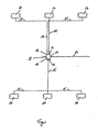
- the single figure shows a level control valve 11, which is used in an air suspension system of a commercial vehicle.
- the invention is not limited to air suspension, but generally relates to suspension systems comprising a gas as a spring means.
- the valve 11 has a compressed air inlet 16 which is connected to a supply line 14.
- the supply line 14 connects the valve 11 to a gas or air supply (not shown), for example a compressed air tank or a compressor.
- the valve 11 has two compressed air outlets 17, which are each connected to a pressure line 15.
- the pressure line 15 connects the valve 11 with bellows 10, wherein according to the embodiment described here six bellows 10 are shown. In principle, any other number of bellows 10 is possible, wherein likewise the number of compressed air outlets 17 of the valve 11 can vary.
- valve 11 also has a control pressure input 12, which is connected to a control pressure line 13.
- the other end of the control pressure line 13 is coupled to a pressure line 15.
- the control pressure line 13 is connected directly to one or more bellows 10. In this way it is achieved that the existing in the bellows 10 pressure is passed simultaneously as a control pressure via the control pressure line 13 to the valve 11.
- the level control valve 11 comprises a pressure outlet 18, which is open to the environment, so that with a corresponding position of the valve 11, pressure can escape from the system, in particular from the bellows 10.
- the pressure lines 15 can be connected by corresponding position of the valve 11 either with the supply line 14 or with the pressure outlet 18 become.
- a connection of the pressure lines 15 to the supply line 14 causes an increase in pressure in the bellows 10, while on the other hand leads a compound of the pressure line 15 to the pressure outlet 18 to a pressure reduction in the bellows 10.
- the tires of the commercial vehicle are deformed, whereby the driving height of the commercial vehicle is reduced.
- the statutory maximum height of the commercial vehicle is just achieved.
- the pressure in the bellows 10 is relatively high. After unloading the utility vehicle, the ride height is increased as the tires assume their original shape. In this case, the pressure within the bellows 10.
- the level control valve 11 causes a connection of the pressure line 15 to the pressure outlet 18, so that the pressure in the bellows 10 is further reduced.
- the pressure in the bellows 10 correlates with the ride height, i. that each value of the Federbalg réelles is assigned a ride height.
- the control of the level control valve 11 is purely mechanical, so that no additional electronic or pneumatic components must be interposed. This is achieved by the level control valve 11, which is operable with a relatively low control pressure. Preferably, the level control valve 11 has a switching pressure of less than 2 bar. In this way, it is possible to use the pressure within the bellows 10 as the control pressure.
- a method is used, in which the level control valve 11 opens depending on the loading state of the commercial vehicle below a certain Federbalgallonss, so that the Federbalgtik is reduced, whereby the ride height is reduced.
- level control valve 11 may close upon reaching the specific Federbalg réelles, so that the particular Federbalg réelle is maintained, whereby the ride height remains constant.
Description
- Die Erfindung betrifft ein Nutzfahrzeug mit einer Gasfederung, insbesondere Luftfederung, gemäß dem Oberbegriff des Anspruchs 1. Ferner betrifft die Erfindung ein Gasfederungssystem für ein Nutzfahrzeug. Ein Nutzfahrzeug der eingangs genannten Art ist aus der
DE 10 2004 051 740 B4 bekannt. - Bei bestimmten Nutzfahrzeugen, beispielsweise Curtainsider-Aufliegern, wird eine maximale lichte Laderaumhöhe angestrebt. Dabei soll die gesetzlich vorgeschriebene, maximale Fahrzeughöhe im beladenen Zustand, wenn die Reifen des Nutzfahrzeugs einen geringeren Halbmesser als im unbeladenen Zustand aufweisen, nicht überschritten werden. Beim Entladen besteht jedoch das Problem, dass durch die Entlastung der Reifen die gesetzlich vorgeschriebene, maximale Fahrzeughöhe überschritten wird.
- Bei Fahrzeugen mit einer Luftfederung ist es daher bekannt, ein Niveauregulierungsventil vorzusehen, das mit Hilfe einer Steuereinheit die Fahrhöhe des Nutzfahrzeugs korrigiert, so dass die gesetzliche Maximalhöhe unterschritten wird. Ein Verfahren zur Änderung des Fahrniveaus bei einem Nutzfahrzeug mit einem elektronisch gesteuerten Niveauregulierungsventil beschreibt beispielsweise die
DE 10 2004 051 740 B4 . Darin ist ein Steuerventil offenbart, das mit den Federbälgen einer Luftfederungsanlage verbunden ist. Das Steuerventil ist ferner mit einer Steuereinrichtung verbunden, die den Zeitpunkt des Öffnens und Schließens des Ventils reguliert. Dabei empfängt die Steuereinrichtung Daten, die Aufschluss über die aktuelle Fahrhöhe des Nutzfahrzeugs geben. Die Daten werden dabei von Sensoren erfasst, die das Ist-Niveau des Fahrzeugs anhand des Abstandes vom Fahrzeugsrahmen zur Fahrzeugachse, der Stoßdämpferhärte, der Achslasten oder der Druckbeaufschlagung der Federbälge ermitteln. - Die Herstellung eines Nutzfahrzeugs mit einem Steuerventil und der vorstehend beschriebenen Steuereinrichtung, ist verhältnismäßig aufwändig, da eine relativ umfangreiche Verkabelung notwendig ist. Ferner benötigen sowohl das Steuerventil, als auch die Steuereinrichtung eine Verbindung zum bordeigenen Stromnetz des Nutzfahrzeugs.
- Der Erfindung liegt die Aufgabe zugrunde, ein Nutzfahrzeug mit einer Gasfederung, insbesondere Luftfederung, anzugeben, dessen Fahrhöhe in Abhängigkeit des Beladezustands einstellbar ist, wobei das Nutzfahrzeug, insbesondere die entsprechende Vorrichtung zur Fahrhöheneinstellung, einfach und kostengünstig herstellbar ist.
- Diese Aufgabe wird erfindungsgemäß im Hinblick auf das Nutzfahrzeug durch den Gegenstand des Anspruchs 1 und im Hinblick auf das Gasfederungssystem durch den Gegenstand des Anspruchs 10 gelöst.
- Die Erfindung beruht auf dem Gedanken, ein Nutzfahrzeug mit einer Gasfederung, insbesondere Luftfederung, anzugeben, die ein oder mehrere zwischen einer Achse und einem Fahrzeugrahmen angeordnete Federbälge umfasst, wobei die Federbälge mit wenigstens einem Niveauregulierungsventil gekoppelt sind derart, dass die Fahrhöhe des Nutzfahrzeugs veränderbar ist. Dabei weist das Niveauregulierungsventil einen Steuerdruckeingang auf, der direkt mit wenigstens einem Federbalg verbunden ist derart, dass die Fahrhöhe des Nutzfahrzeugs in Abhängigkeit vom Druck innerhalb wenigstens eines Federbalgs veränderbar ist.
- Durch die direkte Kopplung des Steuerdruckeingangs mit wenigstens einem Federbalg wird ermöglicht, dass der Druck innerhalb des Federbalgs direkt zur Steuerung der Fahrhöhe verwendet werden kann. Eine aufwändige, elektronische Umsetzung bzw. Regelung ist nicht notwendig. Damit entfällt ebenfalls eine relativ umfangreiche Verkabelung, da das erfindungsgemäße Niveauregulierungsventil rein mechanisch betätigbar ist und für den Betrieb keine elektrische Energieversorgung benötigt. Das erfindungsgemäße Nutzfahrzeug, insbesondere die Gasfederung des erfindungsgemäßen Nutzfahrzeugs, weist im Allgemeinen einen relativ einfachen Aufbau auf, so dass eine einfache, schnelle und kostengünstige Herstellung und Montage gewährleistet ist.
- Bei einer bevorzugten Ausführungsform des erfindungsgemäßen Nutzfahrzeugs ist das Niveauregulierungsventil mit einer Gasversorgung gekoppelt derart, dass die Zufuhr eines Versorgungsdrucks zu wenigstens einem Federbalg in direkter Abhängigkeit eines Steuerdrucks steuerbar ist, wobei der Steuerdruck dem Druck innerhalb des Federbalgs entspricht. Vorteilhafterweise ist das Niveauregulierungsventil zwischen eine Gasversorgung, beispielsweise einem Drucklufttank, und wenigstens einen Federbalg der Gasfederung geschaltet. Der Druck im Federbalg dient dabei als Steuerdruck, in dessen Abhängigkeit das Niveauregulierungsventil betätigbar ist. Je nach Höhe des Steuerdrucks öffnet bzw. sperrt das Niveauregulierungsventil die Verbindung zwischen der Gasversorgung und dem Federbalg. Ferner ist es möglich, dass das Niveauregulierungsventil den wenigstens einen Federbalg mit der Umgebung verbindet, so dass beim Öffnen des Niveauregulierungsventils Gas, insbesondere Luft, aus dem Federbalg entweicht.
- Das Niveauregulierungsventil ist vorzugsweise mit einem Steuerdruck von höchstens drei bar, insbesondere höchstens 2,5 bar, insbesondere höchstens 2 bar, insbesondere höchstens 1,5 bar, betätigbar. Durch diesen relativ geringen Steuerdruck ist gewährleistet, dass das Niveauregulierungsventil direkt durch den Druck innerhalb des Federbalgs gesteuert wird. Eine Anpassung des an das Niveauregulierungsventil geleiteten Federbalgdrucks zur Verwendung als Steuerdruck, beispielsweise durch eine Vorrichtung zur Druckerhöhung, ist nicht notwendig.
- Das Niveauregulierungsventil kann zur Betätigung mit unterschiedlichen Schaltdrücken einstellbar sein. Als Schaltdruck wird der Steuerdruckwert beschrieben, der die Betätigung bzw. Auslösung des Niveauregulierungsventils bewirkt, d.h. bei dem das Ventil öffnet bzw. schließt. Auf diese Weise ist es möglich, das Niveauregulierungsventil bei der Montage in einem Nutzfahrzeug an das Nutzfahrzeug, insbesondere an das Leergewicht des Nutzfahrzeugs, anzupassen. Das Niveauregulierungsventil kann somit universell in verschiedene Nutzfahrzeugtypen eingebaut werden. Bei der Montage wird das Ventil an die Eigenschaften des jeweiligen Fahrzeugtyps angepasst und eingestellt, so dass der Schaltdruck dem Steuerdruck entspricht, bei dem das Nutzfahrzeug die gesetzlich vorgeschriebene Fahrhöhe aufweist. Beispielsweise kann das Niveauregulierungsventil zur Verwendung in Sattelaufliegern, Pritschenfahrzeugen, Kipperfahrzeugen oder Curtainsider-Aufliegern eingesetzt werden.
- Die Erfindung ist nicht darauf beschränkt, dass das Niveauregulierungsventil angepasst ist, die gesetzlich vorgeschriebene Maximalhöhe eines Nutzfahrzeugs einzuhalten. Vielmehr kann eine beliebige Fahrhöhe festgelegt werden, die mit Hilfe des Ventils eingehalten wird. Die Einstellung des Ventils auf die gesetzlich vorgeschriebene Maximalhöhe ist jedoch bevorzugt, um eine maximale Ladehöhe im Innenraum des Nutzfahrzeugs bereitzustellen.
- Bei einer bevorzugten Ausführungsform des erfindungsgemäßen Nutzfahrzeugs ist das Niveauregulierungsventil derart angepasst, dass die Fahrhöhe um höchstens 35 mm, insbesondere höchstens 30 mm, insbesondere höchstens 25 mm, insbesondere höchstens 20 mm, veränderbar ist. Üblicherweise bewirkt die Beladung eines Nutzfahrzeugs eine Verformung der Reifen, so dass der statische Halbmesser der Reifen bei zunehmender Beladung reduziert wird. Beim Entladen nehmen die Reifen wieder ihre ursprüngliche Form ein. Insgesamt führt die Änderung des statischen Halbmessers der Reifen zu einer Änderung der Fahrhöhe des Nutzfahrzeugs um bis zu 25 mm bis 35 mm. Das Niveauregulierungsventil ist daher angepasst, die Fahrhöhenänderung auszugleichen bzw. zu kompensieren. Dadurch, dass das Niveauregulierungsventil gerade die Höhenänderung zwischen beladenem und unbeladenem Zustand des Nutzfahrzeugs ausgleicht, wird die Effizienz und Lebensdauer des Ventils erhöht.
- Vorzugsweise sind mehrere Federbälge mit einem gemeinsamen Niveauregulierungsventil verbunden. Dadurch ist eine Steuerung der Fahrhöhe gleichmäßig möglich, da der Druck innerhalb der Federbälge gleichzeitig verändert wird. Ferner ist der Aufbau der Gasfederung mit einer geringen Anzahl von Niveauregulierungsventilen einfach und kostengünstig.
- Das Niveauregulierungsventil kann ein mechanisches Wegeventil umfassen. Ein derartiges Ventil weist einen besonders einfachen Aufbau und eine hohe Zuverlässigkeit auf.
- Vorzugsweise weist das Wegeventil wenigstens zwei, insbesondere drei, Schaltstellungen zur Einstellung von wenigstens zwei, insbesondere drei, Fahrhöhen auf.
- Bei einer weiteren bevorzugten Ausführungsform ist das Niveauregulierungsventil derart angepasst, dass die Fahrhöhe des Nutzfahrzeugs zusätzlich fremdbetätigt einstellbar ist. Auf diese Weise kann die Fahrhöhe beispielsweise durch einen Anwender, insbesondere den Fahrer des Nutzfahrzeugs, auf ein gewünschtes Niveau eingestellt werden. Beispielsweise kann die Fahrhöhe des Nutzfahrzeugs verändert werden, um die Höhe des Nutzfahrzeugs, insbesondere des Ladebodens, an eine Laderampe anzupassen.
- Die Erfindung beruht ferner auf dem Gedanken, ein Gasfederungssystem, insbesondere Luftfederungssystem, für ein Nutzfahrzeug mit einem oder mehreren zwischen einer Achse und einem Fahrzeugrahmen angeordneten Federbälgen anzugeben, die mit wenigstens einem Niveauregulierungsventil gekoppelt sind derart, dass die Fahrhöhe des Nutzfahrzeugs veränderbar ist, wobei das Niveauregulierungsventil einen Steuerdruckeingang aufweist, der direkt mit wenigstens einem Federbalg verbunden ist derart, dass die Fahrhöhe des Nutzfahrzeugs in Abhängigkeit vom Druck innerhalb wenigstens eines Federbalgs veränderbar ist.
- Die Erfindung wird im Folgenden anhand von Ausführungsbeispielen unter Bezug auf die beigefügte schematische Zeichnung näher erläutert. Darin zeigt die einzige Figur ein Schaltbild einer Gasfederung für ein erfindungsgemäßes Nutzfahrzeug.
- Die einzige Figur zeigt ein Niveauregulierungsventil 11, das in einer Luftfederungsanlage eines Nutzfahrzeugs zum Einsatz kommt. Die Erfindung ist nicht auf Luftfederungen beschränkt, sondern bezieht sich generell auf Federungsanlagen, die ein Gas als Federungsmittel umfassen. Das Ventil 11 weist einen Drucklufteingang 16 auf, der mit einer Versorgungsleitung 14 verbunden ist. Die Versorgungsleitung 14 verbindet das Ventil 11 mit einer Gas- bzw. Luftversorgung (nicht dargestellt), beispielsweise einem Drucklufttank oder einem Kompressor. Ferner weist das Ventil 11 zwei Druckluftausgänge 17 auf, die jeweils mit einer Druckleitung 15 verbunden sind. Die Druckleitung 15 verbindet das Ventil 11 mit Federbälgen 10, wobei gemäß dem hier beschriebenen Ausführungsbeispiel sechs Federbälge 10 dargestellt sind. Grundsätzlich ist jede andere Anzahl von Federbälgen 10 möglich, wobei ebenfalls die Anzahl der Druckluftausgänge 17 des Ventils 11 variieren kann. Wie in der Figur zu erkennen ist, sind jeweils drei Federbälge 10 über die Druckleitung 15 mit einem Druckluftausgang 17 verbunden. Das Ventil 11 weist ferner einen Steuerdruckeingang 12 auf, der mit einer Steuerdruckleitung 13 verbunden ist. Das andere Ende der Steuerdruckleitung 13 ist mit einer Druckleitung 15 gekoppelt. Es ist auch möglich, dass die Steuerdruckleitung 13 direkt mit einem oder mehreren Federbälgen 10 verbunden ist. Auf diese Weise wird erreicht, dass der in den Federbälgen 10 vorhandene Druck gleichzeitig als Steuerdruck über die Steuerdruckleitung 13 an das Ventil 11 geleitet wird. Des Weiteren umfasst das Niveauregulierungsventil 11 einen Druckauslass 18, der zur Umgebung hin offen ist, so dass bei entsprechender Stellung des Ventils 11 Druck aus dem System, insbesondere aus den Federbälgen 10 entweichen kann. Dementsprechend können also die Druckleitungen 15 durch entsprechende Stellung des Ventils 11 entweder mit der Versorgungsleitung 14 oder mit dem Druckauslass 18 verbunden werden. Dabei bewirkt eine Verbindung der Druckleitungen 15 mit der Versorgungsleitung 14 eine Druckerhöhung in den Federbälgen 10, während hingegen eine Verbindung der Druckleitung 15 mit dem Druckauslass 18 zu einer Druckminderung in den Federbälgen 10 führt.
- Aufgrund des höheren Gewichts des Nutzfahrzeugs im beladenen Zustand sind die Reifen des Nutzfahrzeugs verformt, wodurch die Fahrhöhe des Nutzfahrzeugs reduziert ist. Üblicherweise wird die gesetzlich vorgeschriebene Maximalhöhe des Nutzfahrzeugs dadurch gerade erreicht. Der Druck in den Federbälgen 10 ist dabei relativ hoch. Nach dem Entladen des Nutzfahrzeugs ist die Fahrhöhe erhöht, da die Reifen ihre ursprüngliche Form annehmen. Dabei sinkt der Druck innerhalb der Federbälge 10. Um die maximal vorgeschriebene Fahrhöhe nicht zu überschreiten, bewirkt das Niveauregulierungsventil 11 eine Verbindung der Druckleitung 15 mit dem Druckauslass 18, so dass der Druck in den Federbälgen 10 weiter reduziert wird. Der Druck in den Federbälgen 10 korreliert mit der Fahrhöhe, d.h. dass jedem Wert des Federbalgdrucks eine Fahrhöhe zugeordnet ist. Sobald der Druck im Federbalg 10 erreicht wird, der der gesetzlich vorgeschriebenen Fahrzeughöhe entspricht, schließt bzw. sperrt das Ventil 11 die Verbindung zwischen Druckleitung 15 und Druckauslass 18, so dass der Federbalgdruck und die Fahrhöhe gehalten werden.
- Die Steuerung des Niveauregulierungsventils 11 erfolgt rein mechanisch, so dass keine zusätzlichen elektronischen oder pneumatischen Bauteile zwischengeschaltet werden müssen. Dies wird durch das Niveauregulierungsventil 11 erreicht, das mit einem relativ geringen Steuerdruck betätigbar ist. Vorzugsweise weist das Niveauregulierungsventil 11 einen Schaltdruck von weniger als 2 bar auf. Auf diese Weise ist es möglich, den Druck innerhalb des Federbalgs 10 als Steuerdruck zu verwenden.
- Vorzugsweise kommt zum Ändern der Fahrhöhe eines Nutzfahrzeugs mit einer Gasfederung, insbesondere Luftfederung, die einen oder mehrere zwischen einer Achse und einem Fahrzeugrahmen angeordnete Federbälge 10 umfasst, die mit wenigstens einem Steuerdruckeingang 12 eines Niveauregulierungsventil 11 direkt gekoppelt sind, ein Verfahren zum Einsatz, bei dem das Niveauregulierungsventil 11 abhängig vom Beladezustand des Nutzfahrzeugs unterhalb eines bestimmten Federbalgdrucks öffnet, so dass der Federbalgdruck reduziert wird, wodurch auch die Fahrhöhe verringert wird.
- Ferner kann das Niveauregulierungsventil 11 bei Erreichen des bestimmten Federbalgdrucks schließen, so dass der bestimmte Federbalgdruck gehalten wird, wodurch auch die Fahrhöhe konstant bleibt.
-
- 10
- Federbalg
- 11
- Niveauregulierungsventil
- 12
- Steuerdruckeingang
- 13
- Steuerdruckleitung
- 14
- Versorgungsleitung
- 15
- Druckleitung
- 16
- Drucklufteingang
- 17
- Druckluftausgang
- 18
- Druckauslass
Claims (10)
- Nutzfahrzeug mit einer Gasfederung, insbesondere Luftfederung, die einen oder mehrere zwischen einer Achse und einem Fahrzeugrahmen angeordnete Federbälge (10) umfasst, wobei die Federbälge (10) mit wenigstens einem Niveauregulierungsventil (11) gekoppelt sind derart, dass die Fahrhöhe des Nutzfahrzeugs veränderbar ist,
dadurch gekennzeichnet,dass
das Niveauregulierungsventil (11) einen Steuerdruckeingang (12) aufweist, der direkt mit wenigstens einem Federbalg (10) verbunden ist derart, dass die Fahrhöhe des Nutzfahrzeugs in Abhängigkeit vom Druck innerhalb wenigstens eines Federbalgs (10) veränderbar ist. - Nutzfahrzeug nach Anspruch 1,
dadurch gekennzeichnet,dass
das Niveauregulierungsventil (11) mit einer Gasversorgung gekoppelt ist derart, dass die Zufuhr eines Versorgungsdrucks zu wenigstens einem Federbalg (10) in direkter Abhängigkeit eines Steuerdrucks steuerbar ist, wobei der Steuerdruck dem Druck innerhalb des Federbalgs (10) entspricht. - Nutzfahrzeug nach Anspruch 1 oder 2,
dadurch gekennzeichnet,dass
das Niveauregulierungsventil (11) mit einem Steuerdruck von höchstens 3 bar, insbesondere höchstens 2,5 bar, insbesondere höchstens 2 bar, insbesondere höchstens 1,5 bar, betätigbar ist. - Nutzfahrzeug nach wenigstens einem der Ansprüche 1 bis 3,
dadurch gekennzeichnet,dass
das Niveauregulierungsventil (11) zur Betätigung mit unterschiedlichen Schaltdrücken einstellbar ist. - Nutzfahrzeug nach wenigstens einem der Ansprüche 1 bis 4,
dadurch gekennzeichnet,dass
das Niveauregulierungsventil (11) angepasst ist derart, dass die Fahrhöhe um höchstens 35 mm, insbesondere höchstens 30 mm, insbesondere höchstens 25 mm, insbesondere höchstens 20 mm, veränderbar ist. - Nutzfahrzeug nach wenigstens einem der Ansprüche 1 bis 5,
dadurch gekennzeichnet,dass
mehrere Federbälge (10) mit einem gemeinsamen Niveauregulierungsventil (11) verbunden sind. - Nutzfahrzeug nach wenigstens einem der Ansprüche 1 bis 6,
dadurch gekennzeichnet,dass
das Niveauregulierungsventil (11) ein mechanisches Wegeventil umfasst. - Nutzfahrzeug nach Anspruch 7,
dadurch gekennzeichnet,dass
das Wegeventil wenigstens zwei, insbesondere drei, Schaltstellungen zur Einstellung von wenigstens zwei, insbesondere drei, Fahrhöhen aufweist. - Nutzfahrzeug nach wenigstens einem der Ansprüche 1 bis 8,
dadurch gekennzeichnet, dass
das Niveauregulierungsventil (11) angepasst ist derart, dass die Fahrhöhe des Nutzfahrzeugs zusätzlich fremdbetätigt einstellbar ist. - Gasfederungssystem, insbesondere Luftfederungssystem, für ein Nutzfahrzeug mit einem oder mehreren zwischen einer Achse und einem Fahrzeugrahmen angeordneten Federbälgen (10), die mit wenigstens einem Niveauregulierungsventil (11) gekoppelt sind derart, dass die Fahrhöhe des Nutzfahrzeugs veränderbar ist,
dadurch gekennzeichnet, dass
das Niveauregulierungsventil (11) einen Steuerdruckeingang (12) aufweist, der direkt mit wenigstens einem Federbalg (10) verbunden ist derart, dass die Fahrhöhe des Nutzfahrzeugs in Abhängigkeit vom Druck innerhalb wenigstens eines Federbalgs (10) veränderbar ist.
Priority Applications (1)
| Application Number | Priority Date | Filing Date | Title |
|---|---|---|---|
| PL09004772T PL2106937T3 (pl) | 2008-04-02 | 2009-03-31 | Pojazd użytkowy z zawieszeniem gazowym, zwłaszcza na powietrznym i układ zawieszenia gazowego |
Applications Claiming Priority (1)
| Application Number | Priority Date | Filing Date | Title |
|---|---|---|---|
| DE202008004545U DE202008004545U1 (de) | 2008-04-02 | 2008-04-02 | Nutzfahrzeug mit einer Gasfederung, insbesondere Luftfederung und Gasfederungssystem |
Publications (2)
| Publication Number | Publication Date |
|---|---|
| EP2106937A1 EP2106937A1 (de) | 2009-10-07 |
| EP2106937B1 true EP2106937B1 (de) | 2011-06-29 |
Family
ID=40835348
Family Applications (1)
| Application Number | Title | Priority Date | Filing Date |
|---|---|---|---|
| EP09004772A Not-in-force EP2106937B1 (de) | 2008-04-02 | 2009-03-31 | Nutzfahrzeug mit einer Gasfederung, insbesondere Luftfederung und Gasfederungssystem |
Country Status (5)
| Country | Link |
|---|---|
| EP (1) | EP2106937B1 (de) |
| AT (1) | ATE514580T1 (de) |
| DE (1) | DE202008004545U1 (de) |
| ES (1) | ES2368884T3 (de) |
| PL (1) | PL2106937T3 (de) |
Families Citing this family (7)
| Publication number | Priority date | Publication date | Assignee | Title |
|---|---|---|---|---|
| DE102018127189A1 (de) | 2018-10-31 | 2020-04-30 | Man Truck & Bus Se | Kraftfahrzeug und Verfahren zur Höhenanpassung eines höhenverstellbaren Kraftfahrzeugs |
| EP3653411A1 (de) | 2018-11-14 | 2020-05-20 | Ovalo GmbH | Vorrichtung zum verbinden eines federbeines mit einer karosserie |
| DE102018128598A1 (de) | 2018-11-14 | 2020-05-14 | Ovalo Gmbh | Vorrichtung zum Verbinden eines Federbeines mit einer Karosserie |
| EP3653412A1 (de) | 2018-11-14 | 2020-05-20 | Ovalo GmbH | Vorrichtung zum verbinden eines federbeines mit einer karosserie |
| EP3653410A1 (de) | 2018-11-14 | 2020-05-20 | Ovalo GmbH | Vorrichtung zum verbinden eines federbeines mit einer karosserie |
| DE102018128595A1 (de) | 2018-11-14 | 2020-05-14 | Ovalo Gmbh | Vorrichtung zum Verbinden eines Federbeines mit einer Karosserie |
| DE102018128596A1 (de) | 2018-11-14 | 2020-05-14 | Ovalo Gmbh | Vorrichtung zum Verbinden eines Federbeines mit einer Karosserie |
Family Cites Families (5)
| Publication number | Priority date | Publication date | Assignee | Title |
|---|---|---|---|---|
| FR1283959A (fr) * | 1960-12-28 | 1962-02-09 | Renault | Procédé et dispositif pour la correction de niveau et/ou d'assiette pour suspension pneumatique, en particulier hydropneumatique de véhicules |
| GB1211799A (en) * | 1967-04-17 | 1970-11-11 | Autobrzdy Jablonec Narodni Pod | Improvements in or relating to self-levelling pneumatic suspension systems for regulation of constant ground clearance of vehicles |
| DE2363836A1 (de) * | 1973-12-21 | 1975-06-26 | Bosch Gmbh Robert | Niveauregeleinrichtung fuer kraftfahrzeuge |
| US6935625B2 (en) * | 2003-08-18 | 2005-08-30 | Haldex Brake Corporation | Air suspension system with air shut off valve |
| DE102004051740B4 (de) | 2004-10-23 | 2007-06-28 | Haldex Brake Products Gmbh | Verfahren zur Veränderung eines Niveaus eines Nutzfahrzeuges mit Luftfederungsanlage |
-
2008
- 2008-04-02 DE DE202008004545U patent/DE202008004545U1/de not_active Expired - Lifetime
-
2009
- 2009-03-31 EP EP09004772A patent/EP2106937B1/de not_active Not-in-force
- 2009-03-31 AT AT09004772T patent/ATE514580T1/de active
- 2009-03-31 PL PL09004772T patent/PL2106937T3/pl unknown
- 2009-03-31 ES ES09004772T patent/ES2368884T3/es active Active
Also Published As
| Publication number | Publication date |
|---|---|
| PL2106937T3 (pl) | 2011-11-30 |
| ES2368884T3 (es) | 2011-11-23 |
| DE202008004545U1 (de) | 2009-10-08 |
| ATE514580T1 (de) | 2011-07-15 |
| EP2106937A1 (de) | 2009-10-07 |
Similar Documents
| Publication | Publication Date | Title |
|---|---|---|
| EP2106937B1 (de) | Nutzfahrzeug mit einer Gasfederung, insbesondere Luftfederung und Gasfederungssystem | |
| DE102005017590B3 (de) | Umschaltventil für Anlagen mit einem Niveauregelventil zum gesteuerten Konstanthalten der Höhe eines Kraftfahrzeugs | |
| EP2794308B1 (de) | Luftfederungsanlage eines kraftfahrzeugs und verfahren zu deren steuerung | |
| DE102007008159B4 (de) | Luftfederungseinrichtung mit elektrisch betätigtem Sperrventil | |
| DE102008051546B4 (de) | Luftfederanlage für einen Kraftwagen mit wenigstens einer Ventilanordnung für eine Liftachse des Kraftwagens | |
| DE102005030467B4 (de) | Luftfederungseinrichtung für Fahrzeuge mit Drossel | |
| EP3487718A1 (de) | Feder- und dämpfungsanordnung für ein motorrad | |
| EP2239157B1 (de) | Ventileinrichtung für eine Luftfederungsanlage | |
| EP3050725A1 (de) | Blockierungsvorrichtung für Fahrzeugfederungen | |
| DE102008017702B4 (de) | Achshebevorrichtung und Verfahren zum Anheben einer Achse | |
| EP3616947A2 (de) | Druckluftvorrichtung für eine luftfederung eines kraftfahrzeugs, kraftfahrzeug und verfahren zum betrieb einer druckluftvorrichtung | |
| DE102015115082B4 (de) | Ventileinheit für pneumatische Anwendungen sowie Luftfederungsanlage | |
| WO2009132895A1 (de) | Verfahren zum steuern oder regeln einer niveauregelanlage | |
| EP2177381B1 (de) | Ventileinrichtung für eine Luftfederungsanlage | |
| DE102013100295B4 (de) | Luftfederanlage für ein Fahrzeug | |
| EP2662228B1 (de) | Luftfederung eines Nutzfahrzeugs mit Achslastumschaltung zwischen Hinterachse und Vor- oder Nachlaufachse | |
| DE102005017591B3 (de) | Steueranlage für den Aufbau eines luftgefederten Kraftfahrzeuges, mit einem Niveauregelventil mit zwei Luftfederkreisen | |
| EP0716944A2 (de) | Pneumatisches Federungsaggregat | |
| DE102010010605B4 (de) | Vorrichtung zur Steuerung von pneumatischen Einrichtungen eines Anhängers | |
| EP1078784A2 (de) | Niveauregelsystem mit einem Druckspeicher für ein Fahrzeug mit Luftfedern | |
| DE102010018606A1 (de) | Vorrichtung und Verfahren zum Sensieren von mehreren Drücken | |
| DE102008021648A1 (de) | Niveauregelanordnung eines Fahrzeugaufbaus luftgefederter Fahrzeuge | |
| AT515172A1 (de) | Anhänger | |
| EP2957441B1 (de) | Luftfederungseinrichtung zum heben und senken eines fahrzeugaufbaus | |
| DE69723281T2 (de) | Niveauregeleinrichtung |
Legal Events
| Date | Code | Title | Description |
|---|---|---|---|
| PUAI | Public reference made under article 153(3) epc to a published international application that has entered the european phase |
Free format text: ORIGINAL CODE: 0009012 |
|
| AK | Designated contracting states |
Kind code of ref document: A1 Designated state(s): AT BE BG CH CY CZ DE DK EE ES FI FR GB GR HR HU IE IS IT LI LT LU LV MC MK MT NL NO PL PT RO SE SI SK TR |
|
| AX | Request for extension of the european patent |
Extension state: AL BA RS |
|
| 17P | Request for examination filed |
Effective date: 20100406 |
|
| AKX | Designation fees paid |
Designated state(s): AT BE BG CH CY CZ DE DK EE ES FI FR GB GR HR HU IE IS IT LI LT LU LV MC MK MT NL NO PL PT RO SE SI SK TR |
|
| GRAP | Despatch of communication of intention to grant a patent |
Free format text: ORIGINAL CODE: EPIDOSNIGR1 |
|
| GRAJ | Information related to disapproval of communication of intention to grant by the applicant or resumption of examination proceedings by the epo deleted |
Free format text: ORIGINAL CODE: EPIDOSDIGR1 |
|
| 19U | Interruption of proceedings before grant |
Effective date: 20091030 |
|
| 19W | Proceedings resumed before grant after interruption of proceedings |
Effective date: 20101201 |
|
| GRAP | Despatch of communication of intention to grant a patent |
Free format text: ORIGINAL CODE: EPIDOSNIGR1 |
|
| RAP1 | Party data changed (applicant data changed or rights of an application transferred) |
Owner name: KOEGEL TRAILER GMBH & CO. KG |
|
| GRAS | Grant fee paid |
Free format text: ORIGINAL CODE: EPIDOSNIGR3 |
|
| GRAA | (expected) grant |
Free format text: ORIGINAL CODE: 0009210 |
|
| AK | Designated contracting states |
Kind code of ref document: B1 Designated state(s): AT BE BG CH CY CZ DE DK EE ES FI FR GB GR HR HU IE IS IT LI LT LU LV MC MK MT NL NO PL PT RO SE SI SK TR |
|
| REG | Reference to a national code |
Ref country code: GB Ref legal event code: FG4D Free format text: NOT ENGLISH |
|
| REG | Reference to a national code |
Ref country code: CH Ref legal event code: EP |
|
| REG | Reference to a national code |
Ref country code: IE Ref legal event code: FG4D Free format text: LANGUAGE OF EP DOCUMENT: GERMAN |
|
| REG | Reference to a national code |
Ref country code: DE Ref legal event code: R096 Ref document number: 502009000841 Country of ref document: DE Effective date: 20110825 |
|
| REG | Reference to a national code |
Ref country code: NL Ref legal event code: VDEP Effective date: 20110629 |
|
| PG25 | Lapsed in a contracting state [announced via postgrant information from national office to epo] |
Ref country code: HR Free format text: LAPSE BECAUSE OF FAILURE TO SUBMIT A TRANSLATION OF THE DESCRIPTION OR TO PAY THE FEE WITHIN THE PRESCRIBED TIME-LIMIT Effective date: 20110629 Ref country code: NO Free format text: LAPSE BECAUSE OF FAILURE TO SUBMIT A TRANSLATION OF THE DESCRIPTION OR TO PAY THE FEE WITHIN THE PRESCRIBED TIME-LIMIT Effective date: 20110929 Ref country code: SE Free format text: LAPSE BECAUSE OF FAILURE TO SUBMIT A TRANSLATION OF THE DESCRIPTION OR TO PAY THE FEE WITHIN THE PRESCRIBED TIME-LIMIT Effective date: 20110629 Ref country code: LT Free format text: LAPSE BECAUSE OF FAILURE TO SUBMIT A TRANSLATION OF THE DESCRIPTION OR TO PAY THE FEE WITHIN THE PRESCRIBED TIME-LIMIT Effective date: 20110629 |
|
| REG | Reference to a national code |
Ref country code: ES Ref legal event code: FG2A Ref document number: 2368884 Country of ref document: ES Kind code of ref document: T3 Effective date: 20111123 |
|
| PG25 | Lapsed in a contracting state [announced via postgrant information from national office to epo] |
Ref country code: GR Free format text: LAPSE BECAUSE OF FAILURE TO SUBMIT A TRANSLATION OF THE DESCRIPTION OR TO PAY THE FEE WITHIN THE PRESCRIBED TIME-LIMIT Effective date: 20110930 Ref country code: SI Free format text: LAPSE BECAUSE OF FAILURE TO SUBMIT A TRANSLATION OF THE DESCRIPTION OR TO PAY THE FEE WITHIN THE PRESCRIBED TIME-LIMIT Effective date: 20110629 Ref country code: LV Free format text: LAPSE BECAUSE OF FAILURE TO SUBMIT A TRANSLATION OF THE DESCRIPTION OR TO PAY THE FEE WITHIN THE PRESCRIBED TIME-LIMIT Effective date: 20110629 Ref country code: FI Free format text: LAPSE BECAUSE OF FAILURE TO SUBMIT A TRANSLATION OF THE DESCRIPTION OR TO PAY THE FEE WITHIN THE PRESCRIBED TIME-LIMIT Effective date: 20110629 |
|
| REG | Reference to a national code |
Ref country code: PL Ref legal event code: T3 |
|
| RAP2 | Party data changed (patent owner data changed or rights of a patent transferred) |
Owner name: KOEGEL TRAILER GMBH & CO. KG |
|
| REG | Reference to a national code |
Ref country code: IE Ref legal event code: FD4D |
|
| PG25 | Lapsed in a contracting state [announced via postgrant information from national office to epo] |
Ref country code: PT Free format text: LAPSE BECAUSE OF FAILURE TO SUBMIT A TRANSLATION OF THE DESCRIPTION OR TO PAY THE FEE WITHIN THE PRESCRIBED TIME-LIMIT Effective date: 20111031 Ref country code: NL Free format text: LAPSE BECAUSE OF FAILURE TO SUBMIT A TRANSLATION OF THE DESCRIPTION OR TO PAY THE FEE WITHIN THE PRESCRIBED TIME-LIMIT Effective date: 20110629 Ref country code: CZ Free format text: LAPSE BECAUSE OF FAILURE TO SUBMIT A TRANSLATION OF THE DESCRIPTION OR TO PAY THE FEE WITHIN THE PRESCRIBED TIME-LIMIT Effective date: 20110629 Ref country code: IE Free format text: LAPSE BECAUSE OF FAILURE TO SUBMIT A TRANSLATION OF THE DESCRIPTION OR TO PAY THE FEE WITHIN THE PRESCRIBED TIME-LIMIT Effective date: 20110629 Ref country code: EE Free format text: LAPSE BECAUSE OF FAILURE TO SUBMIT A TRANSLATION OF THE DESCRIPTION OR TO PAY THE FEE WITHIN THE PRESCRIBED TIME-LIMIT Effective date: 20110629 Ref country code: IS Free format text: LAPSE BECAUSE OF FAILURE TO SUBMIT A TRANSLATION OF THE DESCRIPTION OR TO PAY THE FEE WITHIN THE PRESCRIBED TIME-LIMIT Effective date: 20111029 |
|
| REG | Reference to a national code |
Ref country code: DE Ref legal event code: R082 Ref document number: 502009000841 Country of ref document: DE Representative=s name: MEISSNER, BOLTE & PARTNER GBR, DE |
|
| PG25 | Lapsed in a contracting state [announced via postgrant information from national office to epo] |
Ref country code: RO Free format text: LAPSE BECAUSE OF FAILURE TO SUBMIT A TRANSLATION OF THE DESCRIPTION OR TO PAY THE FEE WITHIN THE PRESCRIBED TIME-LIMIT Effective date: 20110629 Ref country code: SK Free format text: LAPSE BECAUSE OF FAILURE TO SUBMIT A TRANSLATION OF THE DESCRIPTION OR TO PAY THE FEE WITHIN THE PRESCRIBED TIME-LIMIT Effective date: 20110629 Ref country code: CY Free format text: LAPSE BECAUSE OF FAILURE TO SUBMIT A TRANSLATION OF THE DESCRIPTION OR TO PAY THE FEE WITHIN THE PRESCRIBED TIME-LIMIT Effective date: 20110629 |
|
| REG | Reference to a national code |
Ref country code: DE Ref legal event code: R081 Ref document number: 502009000841 Country of ref document: DE Owner name: KOEGEL TRAILER GMBH & CO. KG, DE Free format text: FORMER OWNER: KOEGEL TRAILER GMBH & CO. KG, 86368 GERSTHOFEN, DE Effective date: 20120217 Ref country code: DE Ref legal event code: R081 Ref document number: 502009000841 Country of ref document: DE Owner name: KOEGEL TRAILER GMBH & CO. KG, DE Free format text: FORMER OWNER: KOEGEL TRAILER GMBH & CO. KG, 86368 GERSTHOFEN, DE Effective date: 20110704 Ref country code: DE Ref legal event code: R082 Ref document number: 502009000841 Country of ref document: DE Representative=s name: MEISSNER, BOLTE & PARTNER GBR, DE Effective date: 20120217 Ref country code: DE Ref legal event code: R082 Ref document number: 502009000841 Country of ref document: DE Representative=s name: MEISSNER BOLTE PATENTANWAELTE RECHTSANWAELTE P, DE Effective date: 20120217 |
|
| PLBE | No opposition filed within time limit |
Free format text: ORIGINAL CODE: 0009261 |
|
| STAA | Information on the status of an ep patent application or granted ep patent |
Free format text: STATUS: NO OPPOSITION FILED WITHIN TIME LIMIT |
|
| 26N | No opposition filed |
Effective date: 20120330 |
|
| PG25 | Lapsed in a contracting state [announced via postgrant information from national office to epo] |
Ref country code: DK Free format text: LAPSE BECAUSE OF FAILURE TO SUBMIT A TRANSLATION OF THE DESCRIPTION OR TO PAY THE FEE WITHIN THE PRESCRIBED TIME-LIMIT Effective date: 20110629 |
|
| REG | Reference to a national code |
Ref country code: DE Ref legal event code: R097 Ref document number: 502009000841 Country of ref document: DE Effective date: 20120330 |
|
| BERE | Be: lapsed |
Owner name: KOGEL TRAILER G.M.B.H. & CO. KG Effective date: 20120331 |
|
| PG25 | Lapsed in a contracting state [announced via postgrant information from national office to epo] |
Ref country code: MC Free format text: LAPSE BECAUSE OF NON-PAYMENT OF DUE FEES Effective date: 20120331 |
|
| PG25 | Lapsed in a contracting state [announced via postgrant information from national office to epo] |
Ref country code: BE Free format text: LAPSE BECAUSE OF NON-PAYMENT OF DUE FEES Effective date: 20120331 |
|
| PG25 | Lapsed in a contracting state [announced via postgrant information from national office to epo] |
Ref country code: MK Free format text: LAPSE BECAUSE OF FAILURE TO SUBMIT A TRANSLATION OF THE DESCRIPTION OR TO PAY THE FEE WITHIN THE PRESCRIBED TIME-LIMIT Effective date: 20110629 |
|
| PG25 | Lapsed in a contracting state [announced via postgrant information from national office to epo] |
Ref country code: BG Free format text: LAPSE BECAUSE OF FAILURE TO SUBMIT A TRANSLATION OF THE DESCRIPTION OR TO PAY THE FEE WITHIN THE PRESCRIBED TIME-LIMIT Effective date: 20110929 |
|
| PG25 | Lapsed in a contracting state [announced via postgrant information from national office to epo] |
Ref country code: MT Free format text: LAPSE BECAUSE OF FAILURE TO SUBMIT A TRANSLATION OF THE DESCRIPTION OR TO PAY THE FEE WITHIN THE PRESCRIBED TIME-LIMIT Effective date: 20110629 |
|
| REG | Reference to a national code |
Ref country code: CH Ref legal event code: PL |
|
| GBPC | Gb: european patent ceased through non-payment of renewal fee |
Effective date: 20130331 |
|
| PG25 | Lapsed in a contracting state [announced via postgrant information from national office to epo] |
Ref country code: CH Free format text: LAPSE BECAUSE OF NON-PAYMENT OF DUE FEES Effective date: 20130331 Ref country code: GB Free format text: LAPSE BECAUSE OF NON-PAYMENT OF DUE FEES Effective date: 20130331 Ref country code: LI Free format text: LAPSE BECAUSE OF NON-PAYMENT OF DUE FEES Effective date: 20130331 |
|
| PG25 | Lapsed in a contracting state [announced via postgrant information from national office to epo] |
Ref country code: LU Free format text: LAPSE BECAUSE OF NON-PAYMENT OF DUE FEES Effective date: 20120331 |
|
| PG25 | Lapsed in a contracting state [announced via postgrant information from national office to epo] |
Ref country code: HU Free format text: LAPSE BECAUSE OF FAILURE TO SUBMIT A TRANSLATION OF THE DESCRIPTION OR TO PAY THE FEE WITHIN THE PRESCRIBED TIME-LIMIT Effective date: 20090331 |
|
| REG | Reference to a national code |
Ref country code: FR Ref legal event code: PLFP Year of fee payment: 8 |
|
| PG25 | Lapsed in a contracting state [announced via postgrant information from national office to epo] |
Ref country code: IT Free format text: LAPSE BECAUSE OF NON-PAYMENT OF DUE FEES Effective date: 20160331 |
|
| REG | Reference to a national code |
Ref country code: FR Ref legal event code: PLFP Year of fee payment: 9 |
|
| PG25 | Lapsed in a contracting state [announced via postgrant information from national office to epo] |
Ref country code: IT Free format text: LAPSE BECAUSE OF NON-PAYMENT OF DUE FEES Effective date: 20160331 |
|
| PGRI | Patent reinstated in contracting state [announced from national office to epo] |
Ref country code: IT Effective date: 20170710 |
|
| REG | Reference to a national code |
Ref country code: FR Ref legal event code: PLFP Year of fee payment: 10 |
|
| REG | Reference to a national code |
Ref country code: DE Ref legal event code: R082 Ref document number: 502009000841 Country of ref document: DE Representative=s name: MEISSNER BOLTE PATENTANWAELTE RECHTSANWAELTE P, DE Ref country code: DE Ref legal event code: R081 Ref document number: 502009000841 Country of ref document: DE Owner name: KOEGEL TRAILER GMBH, DE Free format text: FORMER OWNER: KOEGEL TRAILER GMBH & CO. KG, 89349 BURTENBACH, DE |
|
| PGFP | Annual fee paid to national office [announced via postgrant information from national office to epo] |
Ref country code: FR Payment date: 20190328 Year of fee payment: 11 Ref country code: PL Payment date: 20190311 Year of fee payment: 11 Ref country code: IT Payment date: 20190321 Year of fee payment: 11 Ref country code: DE Payment date: 20190329 Year of fee payment: 11 |
|
| PGFP | Annual fee paid to national office [announced via postgrant information from national office to epo] |
Ref country code: AT Payment date: 20190328 Year of fee payment: 11 Ref country code: TR Payment date: 20190320 Year of fee payment: 11 |
|
| PGFP | Annual fee paid to national office [announced via postgrant information from national office to epo] |
Ref country code: ES Payment date: 20190425 Year of fee payment: 11 |
|
| REG | Reference to a national code |
Ref country code: DE Ref legal event code: R119 Ref document number: 502009000841 Country of ref document: DE |
|
| REG | Reference to a national code |
Ref country code: AT Ref legal event code: MM01 Ref document number: 514580 Country of ref document: AT Kind code of ref document: T Effective date: 20200331 |
|
| REG | Reference to a national code |
Ref country code: AT Ref legal event code: PC Ref document number: 514580 Country of ref document: AT Kind code of ref document: T Owner name: KOEGEL TRAILER GMBH, DE Effective date: 20201102 |
|
| PG25 | Lapsed in a contracting state [announced via postgrant information from national office to epo] |
Ref country code: AT Free format text: LAPSE BECAUSE OF NON-PAYMENT OF DUE FEES Effective date: 20200331 Ref country code: DE Free format text: LAPSE BECAUSE OF NON-PAYMENT OF DUE FEES Effective date: 20201001 Ref country code: FR Free format text: LAPSE BECAUSE OF NON-PAYMENT OF DUE FEES Effective date: 20200331 |
|
| REG | Reference to a national code |
Ref country code: ES Ref legal event code: FD2A Effective date: 20210811 |
|
| PG25 | Lapsed in a contracting state [announced via postgrant information from national office to epo] |
Ref country code: ES Free format text: LAPSE BECAUSE OF NON-PAYMENT OF DUE FEES Effective date: 20200401 |
|
| PG25 | Lapsed in a contracting state [announced via postgrant information from national office to epo] |
Ref country code: PL Free format text: LAPSE BECAUSE OF NON-PAYMENT OF DUE FEES Effective date: 20200331 |
|
| PG25 | Lapsed in a contracting state [announced via postgrant information from national office to epo] |
Ref country code: TR Free format text: LAPSE BECAUSE OF NON-PAYMENT OF DUE FEES Effective date: 20200331 |
|
| PG25 | Lapsed in a contracting state [announced via postgrant information from national office to epo] |
Ref country code: IT Free format text: LAPSE BECAUSE OF NON-PAYMENT OF DUE FEES Effective date: 20200331 |