EP2687075A1 - Auf ein Fahrgestell aufgebaute Einrichtung zur Verteilung von streufähigem Gut - Google Patents
Auf ein Fahrgestell aufgebaute Einrichtung zur Verteilung von streufähigem Gut Download PDFInfo
- Publication number
- EP2687075A1 EP2687075A1 EP13405052.5A EP13405052A EP2687075A1 EP 2687075 A1 EP2687075 A1 EP 2687075A1 EP 13405052 A EP13405052 A EP 13405052A EP 2687075 A1 EP2687075 A1 EP 2687075A1
- Authority
- EP
- European Patent Office
- Prior art keywords
- trough
- discharge
- tub
- frame
- good
- Prior art date
- Legal status (The legal status is an assumption and is not a legal conclusion. Google has not performed a legal analysis and makes no representation as to the accuracy of the status listed.)
- Granted
Links
Images

Classifications
-
- A—HUMAN NECESSITIES
- A01—AGRICULTURE; FORESTRY; ANIMAL HUSBANDRY; HUNTING; TRAPPING; FISHING
- A01C—PLANTING; SOWING; FERTILISING
- A01C3/00—Treating manure; Manuring
- A01C3/06—Manure distributors, e.g. dung distributors
- A01C3/063—Side-spreaders
Definitions
- the invention relates to a device constructed on a chassis for the distribution of streucalledem Good, such as manure, compost, fertilizers or waste from vegetable materials, consisting of a mounted on the chassis and a cargo space for the Good forming trough, along a floor a contiguous Good against a one end of the load compartment forming, laterally from the tub conveying discharge device pushing conveyor, wherein the discharge at least one charged goods for the preparation of grit facing, circumferentially driven crushing device and one of these downstream, acting transversely to the direction of travel ejection device.
- streulessnessem Good such as manure, compost, fertilizers or waste from vegetable materials
- Such devices are mounted on a chassis of a self-propelled transport vehicle or by a tractor or the like. Pulled chassis and fixed, the self-propelled transport vehicles or the towed vehicles are often designed to replace other buildable devices. It is referred to a prospectus of the applicant "gafner The spreader" January 2012, referenced.
- the conveying space with the loading space and connected at one end of the Well receiving tray requires care and maintenance, especially for replacement of wear parts such as knives, conveyor and guide elements better accessibility, in particular due to the relatively high weight of the discharge previously constructive means has not been recognized.
- this object is achieved in that a frame carrying the discharge is at least partially separable by a pivoting or extension movement of the trough, so that the inside resp. the loading space facing side of the discharge cleaned, repaired and the drive and wear parts can be lubricated or replaced.
- the pull-out movement may be a sliding movement with which the discharge device can be pulled away from the trough approximately parallel to the direction of travel and pushed back to the trough.
- the accessibility of the loading space resp. the tub is thus improved, the sustained maintenance carried out advantageously both when built on a chassis device as well as lifted from the chassis device can be.
- the frame is designed as a housing of the discharge, so that a compact design can arise.
- a simple separation of the discharge from the tub can be achieved, that the frame is formed pivotable about an approximately vertical axis of rotation in the side wall portion of the tub.
- This embodiment provides optimum accessibility to the discharge device both on the inside and on the outside, viewed in the direction of travel of the vehicle.
- the axis of rotation could also be arranged horizontally, but such arrangement would improve the accessibility only moderately.
- Another embodiment which falls under the invention could cause a separation of the discharge device and the trough if the discharge device can be separated from the trough by sliding movements and returned again.
- an embodiment of the invention when the frame in the side wall portion of the tub around an approximately vertical axis of rotation is pivotable, which also provides access to the tub, respectively. significantly improved in the hold and the conveyor.
- an attached flange (attachment flange) is attached to the frame. connected to the former, in the operating state of the device resp. the tub is releasably connected to a fixed to the end of the tub flange and ensures in this way a high stability and lock security.
- mounting flange and mating flange are connected by a hinge forming the axis of rotation, so that a simple opening of the loading space resp. Separation of the discharge of the cargo space is possible.
- the flanges are advantageous after the tub resp. Cargo compartment cross-section and formed closed, so that a high stability can be transmitted to both the end of the tub and on the frame.
- the hinge requires a robust design, including at least two spaced, formed from block and rotary belt and slip shaft pivot bearing are provided on the axis of rotation.
- Discharge device and tub are positively and / or non-positively connected in the operating state by the flanges, so that a self-supporting connection is formed, which transmits a high stability to the machine and vehicle parts involved.
- the positive connection of the flanges can be formed by a collar-like attachment to at least one flange, such that the collar of the flange at least partially passes through the other flange.
- the housing of the discharge has a loading space directed towards the connection space for processing resp. Crushing of the material, which is adapted approximately to the cross-sectional shape of the loading space of the tub.
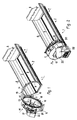
- the Fig. 1 and 2 show different operating conditions of a self-propelled or towed chassis buildable device 1 for the distribution of scatterable good, such as manure, compost, fertilizers or waste from plant materials, such as those incurred primarily in agriculture, gardening and plant construction or processing.
- the device consists of a built on a chassis, not shown, and fixed trough 2, which forms a hold 3 for the distributed on fields or fields to be discharged Good.
- the trough 2 has at one end of the trough 2, a discharge device 4 and at the opposite end in the direction of movement of the device 1 end a loading space wall, respectively. Sliding wall 5 on.
- the side walls 6, 7 of the tub 2 have an upstanding from the side end of the tub bottom 8 and outwardly curved shape and are made of metal.
- the loading space wall 5 is designed as a sliding wall and driven by a circulating chain drive (not visible) to which the discharge device 4 associated end of the loading space 3 and movable back into the starting position.
- a stationary wall could also be provided on the end of the trough 2 opposite to the discharge device 4 and a trough bottom driven along the trough bottom 8 as conveying device.
- the Fig. 1 shows the discharge device 4 in an inoperative position in which they is separated from the tub 2 by a pivoting movement of the operating position.
- the housing 10 or frame is a flange 13 grown resp. attached, in the operating state of the device 1 according to Fig. 2 is releasably connected to a fixed to the tub end flange 14. This operating condition can be achieved by screws or bolts and nuts or suitable closures (not shown) on the flanges 13, 14.
- the movable flange 13 and attached to the tub 2, connected to the chassis mating flange 14 are connected by the hinge 11, respectively. when separated from the tub 2 position of the discharge device 4, the latter depends by means of hinge 11 freely to the tub 2, respectively. a chassis, not shown.
- the hinge 11 consists of two spaced pivot bearings 15, 16, which at the time of a claw respectively. Cantilever band and attached to a the shaft passing through the shaft, attached to the frame 9 of the discharge device 4 rotary belt.
- the flanges 13, 14 respectively. at least one flange 13, 14 formed with a collar-like protruding frame 17, which is brought together to achieve the operating state with the opposite flange 14, 13 form fit.
- the housing 10 of the discharge device 4 forms the cargo space 3 through a connection space, the resp. is used for crushing the Guts and has about the cross-sectional shape of the cargo space 3 of the tub 2, so that a smooth transition arises.
- an ejector 19 is effectively connected.
- the ejection device 19 has an on the periphery of
- Crushing device 18 arranged spin rotor 20, which separates the from the crushing device 18 from the contiguous Good distribution resp. Scattered detected and ejected through a guide channel 21.
- the spin rotor 20 is drive connected to an unillustrated drive shaft, preferably a belt gear guard protected by a removable hood 22.
- the ejection device 19 is adjustable in the direction of the double arrow 23 along the circumference of the crushing device 18, respectively. adjustable trained.
- the mentioned alternative embodiment of the invention in which the discharge device 4 can be separated from the trough 2 by a sliding movement parallel to the direction of travel, is based on a telescopic guide arrangement of tubes or carriers of different cross sections.
- Fig. 3 to 5 the most important components of the device 1 are shown individually, as described above and to be connected to each other, for example by means of screws and nuts.
Landscapes
- Life Sciences & Earth Sciences (AREA)
- Soil Sciences (AREA)
- Environmental Sciences (AREA)
- Fertilizers (AREA)
- Fertilizing (AREA)
Abstract
Description
- Die Erfindung betrifft eine auf ein Fahrgestell aufgebaute Einrichtung zur Verteilung von streufähigem Gut, wie Mist, Kompost, Düngemittel oder Abfälle aus pflanzlichen Stoffen, bestehend aus einer auf dem Fahrgestell befestigten und einen Laderaum für das Gut bildenden Wanne, die entlang eines Bodens eine das zusammenhängende Gut gegen eine ein Ende des Laderaumes bildende, seitlich aus der Wanne fördernde Austragseinrichtung schiebende Fördervorrichtung aufweist, wobei die Austragseinrichtung wenigstens eine dem geladenen Gut zur Aufbereitung von Streugut zugewandte, umlaufend angetriebene Zerkleinerungsvorrichtung und eine dieser nachgeschaltete, quer zur Fortbewegungsrichtung wirkende Auswurfvorrichtung aufweist.
- Solche Einrichtungen sind auf einem Fahrgestell eines selbstfahrenden Transportfahrzeug oder von einem Traktor oder dgl. gezogenen Fahrgestell aufgebaut und befestigt, wobei die selbstfahrenden Transportfahrzeuge oder die gezogenen Fahrzeuge oft zum Austausch anderer aufbaubarer Einrichtungen ausgebildet sind. Es wird auf einen Prospekt der Gesuchstellerin "gafner Der Streuer" herausgegeben Januar 2012, verwiesen.
- Einrichtungen der eingangs beschriebenen Art sind durch die CH-Patenente 683058 A5, 691788 A5 und 692593 A5 oder in diesen zitierten Dokumenten bekannt.
- Die mit dem Laderaum förderwirksam und an einem Ende der das Gut aufnehmenden Wanne verbundene Austragseinrichtung erfordert zur Pflege und zum Unterhalt, insbesondere zum Austausch der Verschleissteile wie Messer, Förder- und Führungselemente eine bessere Zugänglichkeit, die insbesondere aufgrund des relativ hohen Gewichtes der Austragseinrichtung bisher mit konstruktiven Mitteln nicht erkannt worden ist.
- Daraus hat sich an die vorliegende Erfindung die Aufgabe gestellt, eine Einrichtung nach der eingangs beschriebenen Art zu schaffen, dass durch eine einfache Zugänglichkeit zu der Austragseinrichtung die Reinigung und Pflege, insbesondere der Unterhalt und die Austauschbarkeit von Austrags-, Antriebs- und Verschleissteilen verbessert werden kann.
- Erfindungsgemäss wird die Aufgabe dadurch gelöst, dass ein die Austragseinrichtung tragendes Gestell durch eine Schwenk- oder Auszugsbewegung von der Wanne wenigstens teilweise trennbar ist, sodass die Innenseite resp. die dem Laderaum zugewandte Seite der Austragseinrichtung gereinigt, repariert und die Antriebs- und Verschleissteile geschmiert oder ausgetauscht werden können. Die Auszugsbewegung kann eine Schiebebewegung sein, mit der die Austragseinrichtung etwa parallel zur Fortbewegungsrichtung von der Wanne weggezogen und wieder an die Wanne zurückgeschoben werden kann.
- Auch die Zugänglichkeit des Laderaumes resp. der Wanne wird damit verbessert, wobei der nachhaltige Unterhalt sowohl bei auf ein Fahrgestell aufgebauter Einrichtung wie auch bei vom Fahrgestell abgehobener Einrichtung vorteilhaft durchgeführt werden kann.
- Vorzugsweise ist das Gestell als Gehäuse der Austragseinrichtung ausgebildet, sodass eine kompakte Bauweise entstehen kann.
- Eine einfache Trennung der Austragseinrichtung von der Wanne kann dadurch erzielt werden, dass das Gestell im Seitenwandbereich der Wanne um eine etwa senkrechte Drehachse schwenkbar ausgebildet ist. Diese Ausführungsform gewährt eine optimale Zugänglichkeit zu der Austragseinrichtung sowohl an deren Innenseite wie auch an der Aussenseite, in Fortbewegungsrichtung des Fahrzeuges betrachtet.
- Selbstverständlich ist es möglich, die senkrechte Drehachse auf der in Fortbewegungsrichtung eines Fahrzeuges linken oder rechten Seite der Wanne resp. des Fahrgestells anzubringen.
- Die Drehachse könnte auch horizontal angeordnet sein, jedoch würde eine solche Anordnungsweise die Zugänglichkeit nur mässig verbessern.
- Eine andere unter die Erfindung fallende Ausführungsform könnte eine Trennung von Austragseinrichtung und Wanne bewirken, wenn die Austragseinrichtung durch Verschiebebewegungen von der Wanne getrennt und wieder zugestellt werden kann.
- Vorteilhaft erweist sich eine Ausführungsform nach der Erfindung, wenn das Gestell im Seitenwandbereich der Wanne um eine etwa senkrechte Drehachse schwenkbar ausgebildet ist, die auch den Zugang zur Wanne resp. in den Laderaum und zur Fördervorrichtung erheblich verbessert.
- Der einfachheithalber ist an dem Gestell ein angebauter Flansch (Anbauflansch) befestigt resp. mit ersterem verbunden, der im Betriebszustand der Einrichtung resp. der Wanne mit einem an dem Wannenende befestigten Gegenflansch lösbar verbunden ist und auf diese Weise eine hohe Stabilität und Verschlusssicherheit gewährleistet.
- Vorzugsweise sind Anbauflansch und Gegenflansch durch ein die Drehachse bildendes Scharnier verbunden, sodass ein einfaches Öffnen des Laderaumes resp. Trennen der Austragseinrichtung von dem Laderaum möglich wird.
- Vorteilhaft sind die Flansche nach dem Wannen- resp. Laderaumquerschnitt und geschlossen ausgebildet, sodass eine hohe Stabilität sowohl auf das Wannenende als auch auf das Gestell übertragen werden kann.
- Es eignet sich eine selbsttragend wirkende, geschlossene Konstruktion für die Flansche, sodass eine form- und/oder kraftschlüssige Verbindung beim Zusammenschluss entsteht.
- Das Scharnier bedarf einer Robusten Ausführung, wozu an der Drehachse wenigstens zwei beabstandete, aus Kloben- und Drehband sowie Aufsteckwelle gebildete Drehlager vorgesehen sind.
- Austragseinrichtung und Wanne sind im Betriebszustand durch die Flansche form-und/oder kraftschlüssig verbunden, sodass eine selbsttragende Verbindung entsteht, die eine hohe Stabilität auf die beteiligten Maschinen- und Fahrzeugteile überträgt. Der formschlüssige Verbund der Flansche kann durch einen kragenartigen Aufsatz an wenigstens einem Flansch gebildet sein, derart, dass der Kragen des Flansches den anderen Flansch wenigsten teilweise durchsetzt.
- Zweckmässig hat das Gehäuse der Austragseinrichtung einen zum Laderaum hin gerichteten Verbindungsraum zur Aufbereitung resp. Zerkleinerung des Guts, der etwa an die Querschnittsform des Laderaumes der Wanne angepasst ist.
- Es erweist sich als vorteilhaft, wenn die von der Wanne getrennte Austragseinrichtung am Boden abstützbar ausgebildet ist.
- Nachfolgend wird die Erfindung unter Bezugnahme auf den zitierten resp. den zitierenden Stand der Technik und die Zeichnung, auf die bezüglich aller in der Beschreibung nicht näher erwähnten Einzelheiten verwiesen wird, anhand eines Ausführungsbeispiels erläutert. In der Zeichnung zeigen:
- Fig. 1
- eine räumliche Darstellung einer Ausführung nach der erfindungsgemässen Einrichtung mit einer von einer aufbaubaren Wanne getrennten Austragseinrichtung,
- Fig. 2
- eine räumliche Darstellung der in
Fig. 1 gezeigten Einrichtung, bei welcher die Austragseinrichtung mit der Wanne betriebsbereit verbunden ist, - Fig. 3
- eine räumliche Darstellung der von einem Fahrgestell abgehobenen Wanne,
- Fig. 4
- eine räumliche Darstellung der von der Wanne oder dem Fahrgestell getrennten Austragseinrichtung und
- Fig. 5
- eine räumliche Darstellung der von dem Fahrgestell resp. der Wanne getrennten, durch ein Scharnier verbundenen Verbindungsflansche.
- Die
Fig. 1 und 2 zeigen unterschiedliche Betriebszustände einer auf ein selbstfahrendes oder gezogenes Fahrgestell aufbaubaren Einrichtung 1 zur Verteilung von streufähigem Gut, wie Mist, Kompost, Düngemittel oder Abfälle aus pflanzlichen Stoffen, wie sie vornehmlich in der Landwirtschaft, im Garten- und Anlagenbau oder der Verarbeitung anfallen. Die Einrichtung besteht aus einer auf einem nicht dargestellten Fahrgestell aufgebauten und befestigten Wanne 2, die einen Laderaum 3 für das auf Felder oder Äcker verteilt auszutragende Gut bildet. Die Wanne 2 weist an einem Ende der Wanne 2 eine Austragseinrichtung 4 und an dem in Fortbewegungsrichtung der Einrichtung 1 gegenüberliegenden Ende eine Laderaumwand resp. Schiebewand 5 auf. Die Seitenwände 6, 7 der Wanne 2 haben eine vom seitlichen Ende des Wannenbodens 8 hochstehende und nach aussen gekrümmt verlaufende Form und sind aus Metall hergestellt. Die Laderaumwand 5 ist als Schiebewand ausgebildet und von einem umlaufenden Kettenantrieb (nicht sichtbar) zu dem der Austragseinrichtung 4 zugeordneten Ende des Laderaumes 3 und zurück in die Ausgangsposition bewegbar angetrieben. - Anstelle einer Schiebewand 5 könnte auch eine stationäre Wand an dem von der Austragseinrichtung 4 gegenüberliegenden Ende der Wanne 2 und ein entlang des Wannenbodens 8 angetriebener Kratzboden als Fördervorrichtung vorgesehen werden.
- Die
Fig. 1 zeigt die Austragseinrichtung 4 in einem Ausserbetriebsposition, in der sie von der Wanne 2 durch eine Schwenkbewegung von der Betriebsposition getrennt ist. Zu diesem Zweck ist ein die Austragseinrichtung 4 tragendes Gestell 9, das als Gehäuse 10 zum Schutz der Austragseinrichtung 4 ausgebildet ist, am Ende der Seitenwand 6 schenkbar befestigt, wozu ein um eine senkrechte Drehachse 12 angeordnetes Scharnier 11 vorgesehen ist. An dem Gestell 9 bzw. der Austragseinrichtung resp. dem Gehäuse 10 bzw. Rahmen ist ein Flansch 13 angebaut resp. befestigt, der im Betriebszustand der Einrichtung 1 gemässFig. 2 mit einem am Wannenende befestigten Gegenflansch 14 lösbar verbunden ist. Dieser Betriebszustand kann durch Schrauben oder Schrauben und Muttern oder geeignete Verschlüsse (nicht dargestellt) an den Flanschen 13, 14 erreicht werden. Der bewegliche Flansch 13 und der an der Wanne 2 befestigte, mit dem Fahrgestell verbundene Gegenflansch 14 sind durch das Scharnier 11 verbunden resp. bei von der Wanne 2 getrennter Position der Austragseinrichtung 4 hängt letztere mittels Scharnier 11 frei an der Wanne 2 resp. einem nicht dargestellten Fahrgestell. - Das Scharnier 11 besteht aus zwei beabstandeten Drehlagern 15, 16, die wanneseitig aus einem Kloben resp. Klobenband und einem an einer die Kloben durchsetzenden Welle aufgesteckten, an dem Gestell 9 der Austragseinrichtung 4 befestigten Drehband.
- Für eine formschlüssige Verbindung im Betriebszustand der Einrichtung 1 sind die Flansche 13, 14 resp. wenigstens ein Flansch 13, 14 mit einem kragenartig abstehenden Rahmen 17 ausgebildet, der zum Erreichen des Betriebszustandes mit dem gegenüberliegenden Flansch 14, 13 formschlüssig zusammengeführt wird.
- Das Gehäuse 10 der Austragseinrichtung 4 bildet zum Laderaum 3 hin einen Verbindungsraum, der zur Aufbereitung resp. zur Zerkleinerung des Guts benutzt wird und der etwa die Querschnittsform des Laderaums 3 der Wanne 2 aufweist, sodass ein stufenloser Übergang entsteht.
- Mit dem Verbindungsraum resp. dem Innenraum, in dem eine rotierende Zerkleinerungsvorrichtung aus Schneid- und Räumwerkzeugen angeordnet ist, wie beispielsweise in
CH 691788 A5 CH 692593 A5 - Zerkleinerungsvorrichtung 18 angeordneter Schleuderrotor 20, der das von der Zerkleinerungsvorrichtung 18 vom zusammenhängenden Gut abgetrennte Verteil- resp. Streugut erfasst und durch einen Leitkanal 21 auswirft.
- Der Schleuderrotor 20 ist mit einer nicht veranschaulichten Antriebswelle, vorzugsweise durch ein Riemenvorgelege, das durch eine abnehmbare Haube 22 geschützt ist, antriebsverbunden.
- Die Auswurfvorrichtung 19 ist in Richtung des Doppelpfeils 23 entlang des Umfangs der Zerkleinerungsvorrichtung 18 verstellbar resp. einstellbar ausgebildet.
- Bei einer von der Wanne 2 getrennten Position der Austragseinrichtung 4 kann diese durch eine nicht dargestellte Abstützvorrichtung zur Schonung des Scharniers 11 resp. der Flanschverbindung auf dem Boden abgestützt werden.
- Die erwähnte alternative Ausführungsform der Erfindung, bei der die Austragseinrichtung 4 durch eine zur Fortbewegungsrichtung parallele Schiebebewegung von der Wanne 2 getrennt werden kann, basiert auf einer teleskopartigen Führungsanordnung von Rohren oder Trägern unterschiedlicher Querschnitte.
- In den
Fig. 3 bis 5 sind die wichtigsten Komponenten der Einrichtung 1 einzeln dargestellt, wie sle oben beschrieben und beispielsweise durch Schrauben und Muttern miteinander zu verbinden sind.
Claims (11)
- Auf ein Fahrgestell aufgebaute Einrichtung (1) zur Verteilung von streufähigem Gut, wie Mist, Kompost, Düngemittel oder Abfälle aus pflanzlichen Stoffen, bestehend aus einer auf dem Fahrgestell befestigten und einen Laderaum (3) für das Gut bildenden Wanne (2), die entlang eines Wannenbodens (8) eine das zusammenhängende Gut gegen eine ein Ende des Laderaumes (3) bildende, seitlich aus der Wanne (2) fördernde Austragseinrichtung (4) schiebende Fördervorrichtung (5) aufweist, wobei die Austragseinrichtung (4) wenigstens eine dem aufgeladenen Gut zur Aufbereitung von Streugut zugewandte, umlaufend angetriebene Zerkleinerungsvorrichtung (18) und eine dieser nachgeschaltete, quer zur Fortbewegungsrichtung wirkende Auswurfvorrichtung (19) aufweist, dadurch gekennzeichnet, dass ein die Austragseinrichtung (4) tragendes Gestell (9) durch eine Schwenk- oder Auszugsbewegung von der Wanne (2) trennbar ist.
- Einrichtung nach Anspruch 1, dadurch gekennzeichnet, dass das Gestell (9) als Gehäuse (10) der Austragseinrichtung (4) ausgebildet ist.
- Einrichtung nach Anspruch 1 oder 2, dadurch gekennzeichnet, dass das Gestell (9) im Seitenbereich der Wanne (2) um eine etwa senkrechte Drehachse (12) schwenkbar ausgebildet ist.
- Einrichtung nach Anspruch 3, dadurch gekennzeichnet, dass das Gestell (9) resp. das Gehäuse (10) einen angebauten Flansch (13) aufweist, der im Betriebszustand der Einrichtung (1) resp. der Wanne (2) mit einem an dem Wannenende befestigten Gegenflansch (14) lösbar verbunden ist.
- Einrichtung nach einem der Ansprüche 1 bis 4, dadurch gekennzeichnet, dass der angebaute Flansch (13) und der Gegenflansch (14) durch ein die Drehachse (12) bildendes Scharnier (11) verbunden sind.
- Einrichtung nach Anspruch 5, dadurch gekennzeichnet, dass die Flanschen im Betriebszustand der Einrichtung (1) formschlüssig verbunden sind.
- Einrichtung nach Anspruch 5 oder 6, dadurch gekennzeichnet, dass das Scharnier (11) an der Drehachse (12) wenigstens zwei beabstandete, aus Kloben und Drehband sowie Aufsteckwelle gebildete Drehlager (15, 16) aufweist.
- Einrichtung nach einem der Ansprüche 1 bis 7, dadurch gekennzeichnet, dass die Austragseinrichtung (4) mit der Wanne (2) form-und/oder kraftschlüssig verbunden ist.
- Einrichtung nach Anspruch 8, dadurch gekennzeichnet, dass das Gehäuse (10) zum Laderaum (3) hin einen Verbindungsraum zur Aufbereitung resp. Zerkleinerung des Guts und etwa die Querschnittsform des Laderaumes (3) aufweist.
- Einrichtung nach Anspruch 9, dadurch gekennzeichnet, dass der zur Aufbereitung von streufähigem Gut ausgebildete Verbindungsraum mit einer vorzugsweise verstellbaren Auswurfvorrichtung (19) förderwirksam verbunden ist.
- Einrichtung nach einem der Ansprüche 1 bis 10, dadurch gekennzeichnet, dass die von der Wanne (2) getrennte Austragseinrichtung (4) durch eine Stützvorrichtung auf dem Boden abstützbar ist.
Applications Claiming Priority (1)
| Application Number | Priority Date | Filing Date | Title |
|---|---|---|---|
| CH01082/12A CH706746B1 (de) | 2012-07-16 | 2012-07-16 | Einrichtung zur Verteilung von streufähigem Gut. |
Publications (2)
| Publication Number | Publication Date |
|---|---|
| EP2687075A1 true EP2687075A1 (de) | 2014-01-22 |
| EP2687075B1 EP2687075B1 (de) | 2019-07-03 |
Family
ID=48520871
Family Applications (1)
| Application Number | Title | Priority Date | Filing Date |
|---|---|---|---|
| EP13405052.5A Active EP2687075B1 (de) | 2012-07-16 | 2013-05-06 | Einrichtung zur verteilung von streufähigem gut |
Country Status (2)
| Country | Link |
|---|---|
| EP (1) | EP2687075B1 (de) |
| CH (1) | CH706746B1 (de) |
Citations (5)
| Publication number | Priority date | Publication date | Assignee | Title |
|---|---|---|---|---|
| CH683058A5 (de) | 1991-05-21 | 1994-01-14 | Gafner Maschinenbau Ag | Miststreuer. |
| DE9312123U1 (de) * | 1992-08-14 | 1994-04-21 | Fa. Friedrich Stöckl, Hippach | Streuvorrichtung |
| CH691788A5 (de) | 1996-11-13 | 2001-10-31 | Gafner Maschb Ag | Fahrbare Einrichtung zur Verteilung von streufähigem Gut. |
| CH692593A5 (de) | 1997-05-31 | 2002-08-30 | Gafner Maschb Ag | Fahrbare Einrichtung zur Verteilung von streufähigem Gut. |
| EP2243345A1 (de) * | 2009-04-23 | 2010-10-27 | Klaus Stolzlechner | Fahrbare Einrichtung zur Verteilung von streufähigem Gut, wie Dünger, Gülle, Abfällen |
-
2012
- 2012-07-16 CH CH01082/12A patent/CH706746B1/de not_active IP Right Cessation
-
2013
- 2013-05-06 EP EP13405052.5A patent/EP2687075B1/de active Active
Patent Citations (5)
| Publication number | Priority date | Publication date | Assignee | Title |
|---|---|---|---|---|
| CH683058A5 (de) | 1991-05-21 | 1994-01-14 | Gafner Maschinenbau Ag | Miststreuer. |
| DE9312123U1 (de) * | 1992-08-14 | 1994-04-21 | Fa. Friedrich Stöckl, Hippach | Streuvorrichtung |
| CH691788A5 (de) | 1996-11-13 | 2001-10-31 | Gafner Maschb Ag | Fahrbare Einrichtung zur Verteilung von streufähigem Gut. |
| CH692593A5 (de) | 1997-05-31 | 2002-08-30 | Gafner Maschb Ag | Fahrbare Einrichtung zur Verteilung von streufähigem Gut. |
| EP2243345A1 (de) * | 2009-04-23 | 2010-10-27 | Klaus Stolzlechner | Fahrbare Einrichtung zur Verteilung von streufähigem Gut, wie Dünger, Gülle, Abfällen |
Also Published As
| Publication number | Publication date |
|---|---|
| CH706746B1 (de) | 2017-01-31 |
| CH706746A2 (de) | 2014-01-31 |
| EP2687075B1 (de) | 2019-07-03 |
Similar Documents
| Publication | Publication Date | Title |
|---|---|---|
| EP0787425B2 (de) | Häckselmaschine und Fördervorrichtung | |
| DE102012014085A1 (de) | Pflückeinheit, Erntevorsatz und Erntemaschine für Mais oder dergleichen | |
| DE3234657C2 (de) | ||
| DE102012108542A1 (de) | Landwirtschaftliche Erntemaschine | |
| DE1407674A1 (de) | Einrichtung zum Ausbreiten oder Ausstreuen irgendeines Stoffes oder Materials | |
| WO2014012620A1 (de) | Pflückeinheit, erntevorsatz und erntemaschine für mais oder dergleichen | |
| DE19751368A1 (de) | Anbauhäcksler eines Mähdreschers | |
| DE102011118791B4 (de) | Förderband zur Verwendung in einer Fräsvorrichtung und Fräsvorrichtung mit einem solchen Förderband | |
| DE1255379B (de) | Haecksler, insbesondere Vorschubfeldhaecksler | |
| EP2687075B1 (de) | Einrichtung zur verteilung von streufähigem gut | |
| DE202014102286U1 (de) | Bearbeitungsgerät zum Reinigen von Feldfrüchten | |
| DE102017223174A1 (de) | Feldhäcksler mit separater Verarbeitung von Stoffströmen | |
| DE722760C (de) | Auflader mit einem mit mehreren Schoepfstellen versehenen Aufnahmekopf und einem anschliessenden Foerderrohr | |
| CH691788A5 (de) | Fahrbare Einrichtung zur Verteilung von streufähigem Gut. | |
| DE2647469C3 (de) | Antriebsanordnung für die Fräswalze an sog. Silofräsen | |
| DE3708558C2 (de) | ||
| DE102013206515A1 (de) | Fördertrommel mit axial beweglichen Fingern | |
| DE102014206728B4 (de) | Bodenwalze für die Landwirtschaft | |
| DE927717C (de) | Vorrichtung zum Ausstreuen pulverartiger Stoffe | |
| EP4062736A1 (de) | Landwirtschaftliche streuvorrichtung | |
| DE4121328C2 (de) | Transport- und Austragvorrichtung für einen Futtermittelblock | |
| DE1928458A1 (de) | Vorrichtung zum Zufuehren von Schuettgut,insbesondere Vorrichtung zum Zufuehren von Erde in Ein- oder Umtopfmaschinen | |
| CH692593A5 (de) | Fahrbare Einrichtung zur Verteilung von streufähigem Gut. | |
| AT43447B (de) | Düngerstreumaschine. | |
| EP3143858B1 (de) | Gezogene verteilmaschine |
Legal Events
| Date | Code | Title | Description |
|---|---|---|---|
| PUAI | Public reference made under article 153(3) epc to a published international application that has entered the european phase |
Free format text: ORIGINAL CODE: 0009012 |
|
| AK | Designated contracting states |
Kind code of ref document: A1 Designated state(s): AL AT BE BG CH CY CZ DE DK EE ES FI FR GB GR HR HU IE IS IT LI LT LU LV MC MK MT NL NO PL PT RO RS SE SI SK SM TR |
|
| AX | Request for extension of the european patent |
Extension state: BA ME |
|
| 17P | Request for examination filed |
Effective date: 20140716 |
|
| RBV | Designated contracting states (corrected) |
Designated state(s): AL AT BE BG CH CY CZ DE DK EE ES FI FR GB GR HR HU IE IS IT LI LT LU LV MC MK MT NL NO PL PT RO RS SE SI SK SM TR |
|
| 17Q | First examination report despatched |
Effective date: 20160105 |
|
| STAA | Information on the status of an ep patent application or granted ep patent |
Free format text: STATUS: EXAMINATION IS IN PROGRESS |
|
| GRAP | Despatch of communication of intention to grant a patent |
Free format text: ORIGINAL CODE: EPIDOSNIGR1 |
|
| STAA | Information on the status of an ep patent application or granted ep patent |
Free format text: STATUS: GRANT OF PATENT IS INTENDED |
|
| INTG | Intention to grant announced |
Effective date: 20190221 |
|
| GRAS | Grant fee paid |
Free format text: ORIGINAL CODE: EPIDOSNIGR3 |
|
| GRAA | (expected) grant |
Free format text: ORIGINAL CODE: 0009210 |
|
| STAA | Information on the status of an ep patent application or granted ep patent |
Free format text: STATUS: THE PATENT HAS BEEN GRANTED |
|
| AK | Designated contracting states |
Kind code of ref document: B1 Designated state(s): AL AT BE BG CH CY CZ DE DK EE ES FI FR GB GR HR HU IE IS IT LI LT LU LV MC MK MT NL NO PL PT RO RS SE SI SK SM TR |
|
| REG | Reference to a national code |
Ref country code: GB Ref legal event code: FG4D Free format text: NOT ENGLISH |
|
| REG | Reference to a national code |
Ref country code: CH Ref legal event code: EP Ref country code: AT Ref legal event code: REF Ref document number: 1149853 Country of ref document: AT Kind code of ref document: T Effective date: 20190715 |
|
| REG | Reference to a national code |
Ref country code: IE Ref legal event code: FG4D Free format text: LANGUAGE OF EP DOCUMENT: GERMAN |
|
| REG | Reference to a national code |
Ref country code: DE Ref legal event code: R096 Ref document number: 502013013089 Country of ref document: DE |
|
| REG | Reference to a national code |
Ref country code: CH Ref legal event code: NV Representative=s name: WERNER FENNER PATENTANWALT, CH |
|
| REG | Reference to a national code |
Ref country code: NL Ref legal event code: MP Effective date: 20190703 |
|
| REG | Reference to a national code |
Ref country code: LT Ref legal event code: MG4D |
|
| PG25 | Lapsed in a contracting state [announced via postgrant information from national office to epo] |
Ref country code: NL Free format text: LAPSE BECAUSE OF FAILURE TO SUBMIT A TRANSLATION OF THE DESCRIPTION OR TO PAY THE FEE WITHIN THE PRESCRIBED TIME-LIMIT Effective date: 20190703 Ref country code: CZ Free format text: LAPSE BECAUSE OF FAILURE TO SUBMIT A TRANSLATION OF THE DESCRIPTION OR TO PAY THE FEE WITHIN THE PRESCRIBED TIME-LIMIT Effective date: 20190703 Ref country code: BG Free format text: LAPSE BECAUSE OF FAILURE TO SUBMIT A TRANSLATION OF THE DESCRIPTION OR TO PAY THE FEE WITHIN THE PRESCRIBED TIME-LIMIT Effective date: 20191003 Ref country code: PT Free format text: LAPSE BECAUSE OF FAILURE TO SUBMIT A TRANSLATION OF THE DESCRIPTION OR TO PAY THE FEE WITHIN THE PRESCRIBED TIME-LIMIT Effective date: 20191104 Ref country code: NO Free format text: LAPSE BECAUSE OF FAILURE TO SUBMIT A TRANSLATION OF THE DESCRIPTION OR TO PAY THE FEE WITHIN THE PRESCRIBED TIME-LIMIT Effective date: 20191003 Ref country code: FI Free format text: LAPSE BECAUSE OF FAILURE TO SUBMIT A TRANSLATION OF THE DESCRIPTION OR TO PAY THE FEE WITHIN THE PRESCRIBED TIME-LIMIT Effective date: 20190703 Ref country code: LT Free format text: LAPSE BECAUSE OF FAILURE TO SUBMIT A TRANSLATION OF THE DESCRIPTION OR TO PAY THE FEE WITHIN THE PRESCRIBED TIME-LIMIT Effective date: 20190703 Ref country code: SE Free format text: LAPSE BECAUSE OF FAILURE TO SUBMIT A TRANSLATION OF THE DESCRIPTION OR TO PAY THE FEE WITHIN THE PRESCRIBED TIME-LIMIT Effective date: 20190703 Ref country code: HR Free format text: LAPSE BECAUSE OF FAILURE TO SUBMIT A TRANSLATION OF THE DESCRIPTION OR TO PAY THE FEE WITHIN THE PRESCRIBED TIME-LIMIT Effective date: 20190703 |
|
| PG25 | Lapsed in a contracting state [announced via postgrant information from national office to epo] |
Ref country code: AL Free format text: LAPSE BECAUSE OF FAILURE TO SUBMIT A TRANSLATION OF THE DESCRIPTION OR TO PAY THE FEE WITHIN THE PRESCRIBED TIME-LIMIT Effective date: 20190703 Ref country code: LV Free format text: LAPSE BECAUSE OF FAILURE TO SUBMIT A TRANSLATION OF THE DESCRIPTION OR TO PAY THE FEE WITHIN THE PRESCRIBED TIME-LIMIT Effective date: 20190703 Ref country code: RS Free format text: LAPSE BECAUSE OF FAILURE TO SUBMIT A TRANSLATION OF THE DESCRIPTION OR TO PAY THE FEE WITHIN THE PRESCRIBED TIME-LIMIT Effective date: 20190703 Ref country code: IS Free format text: LAPSE BECAUSE OF FAILURE TO SUBMIT A TRANSLATION OF THE DESCRIPTION OR TO PAY THE FEE WITHIN THE PRESCRIBED TIME-LIMIT Effective date: 20191103 Ref country code: GR Free format text: LAPSE BECAUSE OF FAILURE TO SUBMIT A TRANSLATION OF THE DESCRIPTION OR TO PAY THE FEE WITHIN THE PRESCRIBED TIME-LIMIT Effective date: 20191004 Ref country code: ES Free format text: LAPSE BECAUSE OF FAILURE TO SUBMIT A TRANSLATION OF THE DESCRIPTION OR TO PAY THE FEE WITHIN THE PRESCRIBED TIME-LIMIT Effective date: 20190703 |
|
| PG25 | Lapsed in a contracting state [announced via postgrant information from national office to epo] |
Ref country code: TR Free format text: LAPSE BECAUSE OF FAILURE TO SUBMIT A TRANSLATION OF THE DESCRIPTION OR TO PAY THE FEE WITHIN THE PRESCRIBED TIME-LIMIT Effective date: 20190703 |
|
| PG25 | Lapsed in a contracting state [announced via postgrant information from national office to epo] |
Ref country code: PL Free format text: LAPSE BECAUSE OF FAILURE TO SUBMIT A TRANSLATION OF THE DESCRIPTION OR TO PAY THE FEE WITHIN THE PRESCRIBED TIME-LIMIT Effective date: 20190703 Ref country code: DK Free format text: LAPSE BECAUSE OF FAILURE TO SUBMIT A TRANSLATION OF THE DESCRIPTION OR TO PAY THE FEE WITHIN THE PRESCRIBED TIME-LIMIT Effective date: 20190703 Ref country code: EE Free format text: LAPSE BECAUSE OF FAILURE TO SUBMIT A TRANSLATION OF THE DESCRIPTION OR TO PAY THE FEE WITHIN THE PRESCRIBED TIME-LIMIT Effective date: 20190703 Ref country code: RO Free format text: LAPSE BECAUSE OF FAILURE TO SUBMIT A TRANSLATION OF THE DESCRIPTION OR TO PAY THE FEE WITHIN THE PRESCRIBED TIME-LIMIT Effective date: 20190703 |
|
| PG25 | Lapsed in a contracting state [announced via postgrant information from national office to epo] |
Ref country code: SM Free format text: LAPSE BECAUSE OF FAILURE TO SUBMIT A TRANSLATION OF THE DESCRIPTION OR TO PAY THE FEE WITHIN THE PRESCRIBED TIME-LIMIT Effective date: 20190703 Ref country code: SK Free format text: LAPSE BECAUSE OF FAILURE TO SUBMIT A TRANSLATION OF THE DESCRIPTION OR TO PAY THE FEE WITHIN THE PRESCRIBED TIME-LIMIT Effective date: 20190703 Ref country code: IS Free format text: LAPSE BECAUSE OF FAILURE TO SUBMIT A TRANSLATION OF THE DESCRIPTION OR TO PAY THE FEE WITHIN THE PRESCRIBED TIME-LIMIT Effective date: 20200224 |
|
| REG | Reference to a national code |
Ref country code: DE Ref legal event code: R097 Ref document number: 502013013089 Country of ref document: DE |
|
| PLBE | No opposition filed within time limit |
Free format text: ORIGINAL CODE: 0009261 |
|
| STAA | Information on the status of an ep patent application or granted ep patent |
Free format text: STATUS: NO OPPOSITION FILED WITHIN TIME LIMIT |
|
| PG2D | Information on lapse in contracting state deleted |
Ref country code: IS |
|
| 26N | No opposition filed |
Effective date: 20200603 |
|
| PG25 | Lapsed in a contracting state [announced via postgrant information from national office to epo] |
Ref country code: SI Free format text: LAPSE BECAUSE OF FAILURE TO SUBMIT A TRANSLATION OF THE DESCRIPTION OR TO PAY THE FEE WITHIN THE PRESCRIBED TIME-LIMIT Effective date: 20190703 |
|
| REG | Reference to a national code |
Ref country code: CH Ref legal event code: NV Representative=s name: SERAINA FENNER, CH |
|
| PG25 | Lapsed in a contracting state [announced via postgrant information from national office to epo] |
Ref country code: MC Free format text: LAPSE BECAUSE OF FAILURE TO SUBMIT A TRANSLATION OF THE DESCRIPTION OR TO PAY THE FEE WITHIN THE PRESCRIBED TIME-LIMIT Effective date: 20190703 |
|
| REG | Reference to a national code |
Ref country code: BE Ref legal event code: MM Effective date: 20200531 |
|
| GBPC | Gb: european patent ceased through non-payment of renewal fee |
Effective date: 20200506 |
|
| PG25 | Lapsed in a contracting state [announced via postgrant information from national office to epo] |
Ref country code: LU Free format text: LAPSE BECAUSE OF NON-PAYMENT OF DUE FEES Effective date: 20200506 |
|
| PG25 | Lapsed in a contracting state [announced via postgrant information from national office to epo] |
Ref country code: IE Free format text: LAPSE BECAUSE OF NON-PAYMENT OF DUE FEES Effective date: 20200506 Ref country code: GB Free format text: LAPSE BECAUSE OF NON-PAYMENT OF DUE FEES Effective date: 20200506 |
|
| PG25 | Lapsed in a contracting state [announced via postgrant information from national office to epo] |
Ref country code: BE Free format text: LAPSE BECAUSE OF NON-PAYMENT OF DUE FEES Effective date: 20200531 |
|
| PG25 | Lapsed in a contracting state [announced via postgrant information from national office to epo] |
Ref country code: MT Free format text: LAPSE BECAUSE OF FAILURE TO SUBMIT A TRANSLATION OF THE DESCRIPTION OR TO PAY THE FEE WITHIN THE PRESCRIBED TIME-LIMIT Effective date: 20190703 Ref country code: CY Free format text: LAPSE BECAUSE OF FAILURE TO SUBMIT A TRANSLATION OF THE DESCRIPTION OR TO PAY THE FEE WITHIN THE PRESCRIBED TIME-LIMIT Effective date: 20190703 |
|
| PG25 | Lapsed in a contracting state [announced via postgrant information from national office to epo] |
Ref country code: MK Free format text: LAPSE BECAUSE OF FAILURE TO SUBMIT A TRANSLATION OF THE DESCRIPTION OR TO PAY THE FEE WITHIN THE PRESCRIBED TIME-LIMIT Effective date: 20190703 |
|
| P01 | Opt-out of the competence of the unified patent court (upc) registered |
Effective date: 20230528 |
|
| PGFP | Annual fee paid to national office [announced via postgrant information from national office to epo] |
Ref country code: DE Payment date: 20250515 Year of fee payment: 13 |
|
| PGFP | Annual fee paid to national office [announced via postgrant information from national office to epo] |
Ref country code: IT Payment date: 20250529 Year of fee payment: 13 |
|
| PGFP | Annual fee paid to national office [announced via postgrant information from national office to epo] |
Ref country code: FR Payment date: 20250520 Year of fee payment: 13 |
|
| PGFP | Annual fee paid to national office [announced via postgrant information from national office to epo] |
Ref country code: AT Payment date: 20250526 Year of fee payment: 13 |
|
| PGFP | Annual fee paid to national office [announced via postgrant information from national office to epo] |
Ref country code: CH Payment date: 20250818 Year of fee payment: 13 |