EP2685611B1 - Motor und elektrische anlage damit - Google Patents
Motor und elektrische anlage damit Download PDFInfo
- Publication number
- EP2685611B1 EP2685611B1 EP12755764.3A EP12755764A EP2685611B1 EP 2685611 B1 EP2685611 B1 EP 2685611B1 EP 12755764 A EP12755764 A EP 12755764A EP 2685611 B1 EP2685611 B1 EP 2685611B1
- Authority
- EP
- European Patent Office
- Prior art keywords
- iron core
- electric motor
- bearing
- rotating body
- stator
- Prior art date
- Legal status (The legal status is an assumption and is not a legal conclusion. Google has not performed a legal analysis and makes no representation as to the accuracy of the status listed.)
- Active
Links
- XEEYBQQBJWHFJM-UHFFFAOYSA-N Iron Chemical group [Fe] XEEYBQQBJWHFJM-UHFFFAOYSA-N 0.000 claims description 86
- 238000004804 winding Methods 0.000 claims description 13
- 238000003780 insertion Methods 0.000 claims description 10
- 230000037431 insertion Effects 0.000 claims description 10
- 230000002093 peripheral effect Effects 0.000 claims description 10
- 230000000149 penetrating effect Effects 0.000 claims description 4
- 238000005260 corrosion Methods 0.000 description 28
- 230000007797 corrosion Effects 0.000 description 28
- 239000002184 metal Substances 0.000 description 14
- 229910052751 metal Inorganic materials 0.000 description 14
- 238000000034 method Methods 0.000 description 14
- 229920005989 resin Polymers 0.000 description 14
- 239000011347 resin Substances 0.000 description 14
- 238000010586 diagram Methods 0.000 description 10
- 229910052742 iron Inorganic materials 0.000 description 6
- 238000009413 insulation Methods 0.000 description 5
- 239000012778 molding material Substances 0.000 description 5
- 230000004907 flux Effects 0.000 description 4
- 238000005192 partition Methods 0.000 description 3
- 229910000831 Steel Inorganic materials 0.000 description 2
- 238000005299 abrasion Methods 0.000 description 2
- 230000001143 conditioned effect Effects 0.000 description 2
- 238000007796 conventional method Methods 0.000 description 2
- 238000001816 cooling Methods 0.000 description 2
- 230000000694 effects Effects 0.000 description 2
- 238000010438 heat treatment Methods 0.000 description 2
- 239000000314 lubricant Substances 0.000 description 2
- 239000000463 material Substances 0.000 description 2
- 230000005855 radiation Effects 0.000 description 2
- 239000010959 steel Substances 0.000 description 2
- 238000005406 washing Methods 0.000 description 2
- 239000004952 Polyamide Substances 0.000 description 1
- 230000002159 abnormal effect Effects 0.000 description 1
- 238000004378 air conditioning Methods 0.000 description 1
- 230000005540 biological transmission Effects 0.000 description 1
- 238000007664 blowing Methods 0.000 description 1
- 230000015556 catabolic process Effects 0.000 description 1
- 239000000919 ceramic Substances 0.000 description 1
- 230000008859 change Effects 0.000 description 1
- 230000001419 dependent effect Effects 0.000 description 1
- 229920001971 elastomer Polymers 0.000 description 1
- 239000000806 elastomer Substances 0.000 description 1
- 238000010292 electrical insulation Methods 0.000 description 1
- 230000005670 electromagnetic radiation Effects 0.000 description 1
- 239000003822 epoxy resin Substances 0.000 description 1
- 239000011810 insulating material Substances 0.000 description 1
- 239000012212 insulator Substances 0.000 description 1
- 239000007769 metal material Substances 0.000 description 1
- 150000002739 metals Chemical class 0.000 description 1
- 238000000465 moulding Methods 0.000 description 1
- 230000007935 neutral effect Effects 0.000 description 1
- 229920002647 polyamide Polymers 0.000 description 1
- -1 polybutylene terephthalate Polymers 0.000 description 1
- 229920001707 polybutylene terephthalate Polymers 0.000 description 1
- 229920000647 polyepoxide Polymers 0.000 description 1
- 239000000843 powder Substances 0.000 description 1
- 230000009467 reduction Effects 0.000 description 1
- 230000007480 spreading Effects 0.000 description 1
- 229920005992 thermoplastic resin Polymers 0.000 description 1
- 229920001187 thermosetting polymer Polymers 0.000 description 1
- 229920006337 unsaturated polyester resin Polymers 0.000 description 1
- 239000004636 vulcanized rubber Substances 0.000 description 1
- XLYOFNOQVPJJNP-UHFFFAOYSA-N water Substances O XLYOFNOQVPJJNP-UHFFFAOYSA-N 0.000 description 1
Images


Classifications
-
- H—ELECTRICITY
- H02—GENERATION; CONVERSION OR DISTRIBUTION OF ELECTRIC POWER
- H02K—DYNAMO-ELECTRIC MACHINES
- H02K1/00—Details of the magnetic circuit
- H02K1/06—Details of the magnetic circuit characterised by the shape, form or construction
- H02K1/22—Rotating parts of the magnetic circuit
- H02K1/27—Rotor cores with permanent magnets
-
- H—ELECTRICITY
- H02—GENERATION; CONVERSION OR DISTRIBUTION OF ELECTRIC POWER
- H02K—DYNAMO-ELECTRIC MACHINES
- H02K5/00—Casings; Enclosures; Supports
- H02K5/04—Casings or enclosures characterised by the shape, form or construction thereof
- H02K5/16—Means for supporting bearings, e.g. insulating supports or means for fitting bearings in the bearing-shields
- H02K5/173—Means for supporting bearings, e.g. insulating supports or means for fitting bearings in the bearing-shields using bearings with rolling contact, e.g. ball bearings
- H02K5/1732—Means for supporting bearings, e.g. insulating supports or means for fitting bearings in the bearing-shields using bearings with rolling contact, e.g. ball bearings radially supporting the rotary shaft at both ends of the rotor
-
- H—ELECTRICITY
- H02—GENERATION; CONVERSION OR DISTRIBUTION OF ELECTRIC POWER
- H02K—DYNAMO-ELECTRIC MACHINES
- H02K1/00—Details of the magnetic circuit
- H02K1/06—Details of the magnetic circuit characterised by the shape, form or construction
- H02K1/22—Rotating parts of the magnetic circuit
- H02K1/27—Rotor cores with permanent magnets
- H02K1/2706—Inner rotors
- H02K1/272—Inner rotors the magnetisation axis of the magnets being perpendicular to the rotor axis
- H02K1/274—Inner rotors the magnetisation axis of the magnets being perpendicular to the rotor axis the rotor consisting of two or more circumferentially positioned magnets
- H02K1/2753—Inner rotors the magnetisation axis of the magnets being perpendicular to the rotor axis the rotor consisting of two or more circumferentially positioned magnets the rotor consisting of magnets or groups of magnets arranged with alternating polarity
- H02K1/276—Magnets embedded in the magnetic core, e.g. interior permanent magnets [IPM]
-
- H—ELECTRICITY
- H02—GENERATION; CONVERSION OR DISTRIBUTION OF ELECTRIC POWER
- H02K—DYNAMO-ELECTRIC MACHINES
- H02K11/00—Structural association of dynamo-electric machines with electric components or with devices for shielding, monitoring or protection
- H02K11/40—Structural association with grounding devices
Definitions
- the present invention relates to an electric motor and an electric device including the electric motor, and particularly to an electric motor and an electric device including the electric motor improved to suppress occurrence of electrolytic corrosion in the bearing of the electric motor.
- An air conditioner for air conditioning such as cooling and heating, as one of electric devices, generally includes a fan for blowing air and an electric motor for rotary-driving the fan.
- a brushless motor In recent years, so-called brushless motors have been used as electric motors in many cases.
- an inverter of a pulse width modulation system hereinafter, referred to as a PWM system as appropriate
- the PWM system performs switching using high-frequency pulses, and thus unnecessary high-frequency signals are likely to radiate from the brushless motor.
- Patent Literature 1 an air conditioner for reducing high-frequency noise radiated from such an electric motor is conventionally proposed (see Patent Literature 1, for example).
- the technique used in such an air conditioner is to cover the part likely to be affected by radiated noise with a shield case, and to connect the shield case with the earth cable inside the air conditioner.
- the neutral point potential of the winding is not zero, which causes a potential difference between the outer ring and the inner ring of a bearing (hereinafter, referred to as a shaft voltage).
- the shaft voltage includes a high-frequency component caused by switching.
- the shaft voltage reaches the dielectric breakdown voltage of the oil film inside the bearing, micro-current flows inside the bearing and causes electrolytic corrosion inside the bearing.
- the electrolytic corrosion proceeds, a wavy abrasion phenomenon can occur on the bearing inner ring, the bearing outer ring, or bearing balls, which leads to abnormal sound. This is one of the major factors of failures in the electric motor.
- Examples of the specific methods for (1) include using a conductive lubricant in the bearing.
- the conductive lubricant has conductivity deteriorated with a lapse of time, and lacks sliding reliability.
- An alternative method considered is to dispose brushes on the rotating shaft so as to provide electrical continuity. However, this method produces brush abrasion powder and requires space.
- Examples of the specific methods for (2) include replacing the iron balls in the bearing with non-conductive ceramic balls. This method is highly effective in suppressing electrolytic corrosion, but requires high cost. Thus, this method cannot be used for general-purpose electric motors.
- stator iron core and conductive metal bracket are electrically short-circuited so as to change the capacitance and reduce the shaft voltage (see Patent Literature 2, for example).
- the rotor does not have an insulated structure and the impedance of the rotor side (bearing inner-ring side) is in a low state.
- the stator side (bearing outer-ring side) has an insulated structure and thus the impedance is in a high state.
- impedances cause a difference in voltage drop.
- the electric potential of the bearing inner-ring side is high while the electric potential of the bearing outer-ring side is low. This unbalanced state can produce a high shaft voltage.
- Such a high shaft voltage can cause electrolytic corrosion in the bearing.
- Patent Literature 2 In order to avoid such a state, in Patent Literature 2, the following method is used.
- the stator iron core and the bracket are short-circuited so as to eliminate the capacitance component between them. Then, as described above, the impedance of the stator side (bearing outer-ring side) is lowered and approximated to the impedance of the rotor side (bearing inner-ring side).
- the following phenomena and reasons for them are considered.
- the stator iron core and the bearing outer ring are not electrically connected and are disposed with a certain space, and thus the impedance between them is in a high state. Further, since the impedance between them is high, the high-frequency signal generated from the stator iron core attenuates and reaches the bearing outer ring. As a result, a high-frequency voltage at a low electric potential occurs in the bearing outer ring.
- the stator iron core faces the rotor with a small clearance provided between them, and generally the rotor and the rotating shaft are made of conductive metals, and thus the impedance between them is in a low state. Further, since the impedance between them is low, the high-frequency signal generated from the stator iron core reaches the bearing inner ring without attenuation. As a result, a high-frequency voltage at a high electric potential occurs in the bearing inner ring.
- the structure of the brushless motor itself is likely to unbalance the impedance of the rotor side and that of the stator side. This generates an electric potential difference, i.e. a shaft voltage, between the inner ring and the outer ring of the bearing, which causes electrolytic corrosion in the bearing.
- the major source of generating signals that cause such a shaft voltage is the stator iron core that has a winding to be driven by high-frequency switching based on the PWM system wound thereon. That is, since the winding to be driven by high-frequency current is wound on the stator iron core, in the stator iron core, high-frequency signals are generated by driving high-frequency waves as well as magnetic flux generated by the driving current. The generated high-frequency signals are led to the bearing inner ring and the bearing outer ring via space.
- the conventional method as disclosed in Patent Literature 2 has the following problem. That is, this conventional method is to suppress electrolytic corrosion by changing the impedance of the stator side and keeping the electric potential balance between the inner ring and the outer ring of the bearing. In such a method, if the impedance is unbalanced in a usage environment of the electric motor, the following case can be considered. That is, inversely, the shaft voltage is increased and electrolytic corrosion is more likely to occur.
- a heat exchanger generally made of metal makes up a sizable proportion of the inside of the air conditioner.
- a fan connected with a rotating shaft is disposed so as to face this heat exchanger.
- large capacitance is likely to be generated between the heat exchanger and the fan.
- the effect of this capacitance can unbalance the impedance in the electric motor with high possibility. That is, for example, high-frequency signals radiated from the stator iron core flow into the rotating shaft as high-frequency current via the heat exchanger and the fan. This can further increase the electric potential on the bearing inner-ring side.
- JP 2010-158152 A describes a motor and electrical apparatus having the same.
- the motor is driven by an inverter by the PWM method and suppresses electrocorrosion of a bearing.
- the motor includes a stator having a stator core wound with a coil; a rotor which has a rotating body facing the stator and holding a magnet circumferentially and a shaft penetrating the center of the rotating body to be attached to the rotating body; an output-shaft side bearing and a counter output shaft side bearing that support the shaft; a conductive bracket fixing the bearing; and a conductive bracket fixing the bearing.
- the bracket is electrically connected to the bracket, and a dielectric layer is formed between the shaft and the outer periphery of the rotor.
- JP 2004-274859 A describes a rotor and brushless motor.
- the rotor has a ring magnet of a regular polygonal shape on an inner peripheral surface as a fixing surface for improving a fixing force and which can prevent the magnetic efficiency of the magnet from being lowered by adopting the regular polygonal shape on the inner peripheral surface.
- the ring magnet made of a pole orienting magnet magnetized so that poles appear at an equal interval only on the outer peripheral surface of the ring magnet is fixed to a collar provided so as to be rotated integrally with a rotating shaft in the rotor.
- the collar has the outer peripheral surface of a regular octagonal shape having corners of the same number as the number of poles of "8" of the ring magnet as seen from the axial direction.
- the ring magnet has the inner peripheral surface of the same shape as the outer peripheral surface of the collar. This ring magnet is magnetized so that the central part of the pole appearing on the outer peripheral surface is disposed on the straight line of the radial direction which passes through the corner of the inner peripheral surface.
- the invention is defined by the subject-matter of claim 1.
- the dependent claims are directed to advantageous embodiments.
- an electric motor which includes the following elements:
- a dielectric layer is formed between the rotating shaft and the outer circumference of the rotating body, and the dielectric layer has a polygonal shape with the rotating shaft at the center thereof.
- the number of corners of the polygon of the dielectric layer is equal to the number of magnetized poles of the magnet held in the rotating body.
- Each vertex of the polygon of the dielectric layer is disposed with the rotating shaft at the center and is placed correspondingly to the center between poles magnetized in the magnet held in the rotating body.
- the impedance of the rotor side can be adjusted and balanced with the impedance of the stator side. This can reduce the shaft voltage between the bearing inner ring and the bearing outer ring. In this manner, the potential differences between the inner rings and the outer rings of the bearings can be reduced in the two bearings fixed by the conductive brackets. This can suppress electrolytic corrosion in the bearings caused by high-frequency waves caused by PWM, for example, while the fixation strength of the bearings is ensured.
- the dielectric layer having a polygonal shape can prevent idle running caused by rotation of the inner iron core and the outer iron core of the rotor.
- the number of corners of the polygon of the dielectric layer is equal to the number of magnetized poles of the magnet held in the rotating body. This can minimize the unbalance caused by rotation. Further, each vertex of the polygon of the dielectric layer is disposed correspondingly to the center between poles magnetized in the magnet held in the rotating body, with the rotating shaft at the center. With this configuration, the dielectric layer can be disposed without interrupting the flow of magnetic flux generated from the magnet.
- each vertex of the polygon of the dielectric layer is formed into an R (rounded) shape. This can facilitate the workability of the rotor iron core.
- the rotating body has a plurality of insertion holes on the outer peripheral side of the dielectric layer, and a magnet is inserted in each insertion hole.
- the dielectric layer covers at least the magnet on both sides of the rotating body in the axial direction.
- This configuration can prevent misalignment of the magnet.
- the two brackets are electrically connected with each other.
- both brackets at an equal electric potential and suppresses the flow of high-frequency current via the rotating shaft. Further, since both brackets are at the equal electric potential, the potential difference between the inner ring and the outer ring of one bearing is approximated or equal to the potential difference between the inner ring and the outer ring of the other bearing.
- stator iron core may be electrically connected with the ground part.
- the two brackets electrically connected with each other may be further electrically connected with the ground part.
- the stator winding wound on the stator iron core is driven by an inverter of a pulse width modulation system.
- an advantageous electric device includes the above electric motor.
- the shaft voltage generated in two bearings can be suppressed low.
- an electric motor with suppressed electrolytic corrosion and an electric device including the electric motor can be provided.
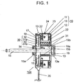
- Fig. 1 is a structural diagram showing a section of electric motor 104 in accordance with the first exemplary embodiment of the present invention.
- a description is provided for an example of a brushless motor using the PWM system, as electric motor 104.
- a description is provided for an inner-rotor type brushless motor, where a rotor is disposed rotatably on the inner circumferential side of a stator.
- stator winding 12 is wound on stator iron core 11 with an insulator interposed between the stator iron core and the winding.
- Stator winding 12 is driven by an inverter of the pulse width modulation system.
- Such stator iron core 11 is molded with insulating resin 13, as a molding material, together with other fixing members. In this exemplary embodiment, these members are integrally molded in this manner so as to form stator 10 having a substantially cylindrical contour.
- Rotor 14 On the inner side of stator 10, rotor 14 is disposed with a clearance provided between them.
- Rotor 14 has disc-shaped or cylindrical-shaped rotating body 30 including metal rotor iron core 31, and has rotating shaft 16 having rotating body 30 fastened thereto so as to penetrate through the center of rotating body 30.
- Rotating body 30 faces the inner circumferential side of stator 10 and holds magnet 32.
- Rotating body 30 is structured such that outer iron core 31 a forming the outer circumferential part of rotor iron core 31, dielectric layer 50, and inner iron core 31b forming the inner circumferential part of rotor iron core 31 are arranged in this order from the outermost circumferential part toward rotating shaft 16 on the inner circumferential side.
- rotating body 30 has a plurality of insertion holes penetrating through rotor iron core 31 in the axial direction, magnets inserted in the respective insertion holes, and dielectric layer 50.
- stator 10 faces the outer circumferential side of rotating body 30.
- bearing 15 for journaling rotating shaft 16 are attached to rotating shaft 16 of rotor 14.
- Each bearing 15 is a cylindrical-shaped bearing including a plurality of iron balls, and the inner-ring side of each bearing 15 is fixed to shaft 16.
- bearing 15a journals rotating shaft 16.
- bearing 15b journals rotating shaft 16.
- bearings 15 are fixed by two conductive metal brackets, on the outer-ring sides of respective bearings 15.
- bearing 15a on the output shaft side is fixed by bracket 17, and bearing 15b opposite the output shaft side is fixed by bracket 19.
- electric motor 104 includes printed circuit board 18 on which a control circuit and a driver circuit are mounted.
- An inverter for driving stator winding 12, for example, is mounted on printed circuit board 18.
- Connection line 20 for the electric power supply of the driver circuit and control signals including a ground line is connected with printed circuit board 18.
- conductive pin 22 is electrically connected with bracket 19 in advance, and these elements are integrally molded.
- the tip of conductive pin 22 is exposed on the end face of stator 10 on the output shaft side, and is electrically connected with bracket 17.
- bracket 17 is electrically connected with bracket 19 inside electric motor 104.
- through-hole 23 is formed in a part of insulating resin 13, i.e. a molding material, and one end of connection pin 24 connected with stator iron core 11 protrudes to the outside through through-hole 23.
- stator iron core 11 When an electric power supply voltage and a control signal are supplied through connection line 20 to electric motor 104 thus configured, the driver circuit on printed circuit board 18 causes a driving current to flow through stator winding 12, and stator iron core 11 generates a magnetic field.
- stator iron core 11 and the magnetic field from magnet 32 generate the attractive force and the repulsive force depending on the polarities of these magnetic fields. These forces rotate rotor 14 around rotating shaft 16 in the center.
- each bearing 15 is fixed and supported by a bracket. Further, in this exemplary embodiment, in order to suppress failures caused by creep as described above, each bearing 15 is fixed by a conductive metal bracket. That is, in this exemplary embodiment, the conductive brackets preformed from a steel sheet with a high dimensional accuracy are used to fix bearings 15. Especially when higher output of electric motor 104 is demanded, such a configuration is more preferable.
- bracket 19 having a diameter of the outer circumference substantially equal to the diameter of the outer circumference of bearing 15b.
- This bracket 19 is integrally molded with insulating resin 13. That is, as shown in Fig. 1 , insulating resin 13 opposite the output shaft side is shaped so as to have body protruding part 13a protruding from the brushless motor body in the direction opposite the output shaft. On the inner side of body protruding part 13a, bracket 19 is disposed as an inner bracket and is integrally molded with insulating resin 13. Bracket 19 has a cup shape formed into a hollow cylinder.
- the bracket has cylindrical portion 19a open on one side, and annular flange portion 19b slightly spreading in the outward direction from the cylindrical end on the open side.
- the diameter of the inner circumference of cylindrical portion 19a is substantially equal to the diameter of the outer circumference of bearing 15b.
- Bearing 15b is inserted into cylindrical portion 19a, and thereby bearing 15b is also fixed to insulating resin 13 via bracket 19.
- the outer-ring side of bearing 15b is fixed to metal bracket 19, so that failures caused by creep can be suppressed.
- the diameter of the outer circumference of flange portion 19b is slightly larger than the diameter of the outer circumference of bearing 15b.
- the diameter of the outer circumference of flange portion 19b is larger than the diameter of the outer circumference of bearing 15b and at least smaller than the diameter of the outer circumference of rotating body 30.
- Bracket 17 has a substantially disc shape, and has a protruding part having a diameter substantially equal to the diameter of the outer circumference of bearing 15a, in the center of the disc shape. This protruding part has a hollow inside.
- bearing 15a is inserted so as to be disposed inside the protruding part of bracket 17.
- bracket 17 is press-fitted to stator 10 such that the connection end formed on the outer circumference of bracket 17 fits to the connection end of stator 10.
- electric motor 104 is formed. With this configuration, the outer-ring side of bearing 15a is fixed to metal bracket 17. Thus, failures caused by creep can be suppressed.
- the electrolytic corrosion is suppressed substantially in the following manner.
- the impedance of the rotor side is increased and approximated to the impedance of the stator side being high impedance. This lowers the electric potential difference between the inner ring and the outer ring of each bearing, i.e. a shaft voltage.
- the configuration that includes this dielectric layer 50 suppresses the transmission of high-frequency signals generated in stator iron core 11 to the fan or the heat exchanger, and reduces the shaft voltage caused by unnecessary radiation from the fan, for example.
- dielectric layer 50 having a polygonal shape can prevent idle running caused by rotation of inner iron core 31b and outer iron core 31a of the rotor.
- the number of corners of the polygon of dielectric layer 50 is equal to the number of magnetized poles of the magnet held in the rotating body. This configuration can minimize the unbalance caused by the rotation.
- the magnet is magnetized with eight poles, and thus dielectric layer 50 has an octagonal shape.
- each vertex of the polygon of dielectric layer 50 is placed correspondingly to the center between poles magnetized in the magnet held in the rotating body, with the rotating shaft at the center. With this configuration, the dielectric layer can be disposed without interrupting the flow of magnetic flux generated from the magnet.
- each vertex of the polygon of dielectric layer 50 is formed into an R (rounded) shape. This can facilitate the workability of the rotor iron core.
- stator iron core 11 is electrically connected with the ground part via connection pin 24. This attenuates the high-frequency signals generated in stator iron core 11 and also reduces the shaft voltage.
- bracket 17 is electrically connected with bracket 19 makes both brackets at an equal electric potential and suppresses a failure such that the shaft voltage of one bracket is high.
- Fig. 2A and Fig. 2B are diagrams each showing a configuration example of rotating body 30 of electric motor 104 in this exemplary embodiment.
- Fig. 2A shows a configuration of rotating body 30 viewed from the top.
- Fig. 2B shows a section taken along line 2B-2B in Fig. 2A .
- rotating body 30 is configured so as to have dielectric layer 50 between rotating shaft 16 and the outer circumference of rotating body 30.
- Dielectric layer 50 has a polygonal shape with rotating shaft 16 at the center, and is disposed in rotating body 30 such that this polygonal shape extends in the axial direction.
- Rotating body 30 has a plurality of insertion holes 33 penetrating through outer iron core 31a in the axial direction, and magnet 32 is inserted in each of insertion holes 33. Further, toward the inner circumferential side, the rotating body has dielectric layer 50 and inner iron core 31b forming rotor iron core 31 that are arranged in this order. This is a structure of the interior permanent magnet (IPM) type.
- IPM interior permanent magnet
- Dielectric layer 50 is a layer formed of an insulating resin.
- Fig. 2A and Fig. 2B show an example of the following case.
- Outer iron core 31a has eight insertion holes 33 with corresponding eight magnets 32 inserted therein, and thus is magnetized with eight poles.
- octagonal dielectric layer 50 is formed such that each vertex of the polygon of dielectric layer 50 is disposed with the rotating shaft at the center, and is placed correspondingly to the center between the poles magnetized in magnet 32.
- rotating body 30 is integrally formed of magnet 32, outer iron core 31a, the insulating resin forming dielectric layer 50, and inner iron core 31b.
- rotating body 30 is fastened to rotating shaft 16.
- rotor 14 journaled by bearings 15 is formed.
- Fig. 3 is a diagram showing a section of another configuration example of rotating body 30.
- dielectric layer 50 is disposed in rotating body 30, and further covers both faces of rotating body 30 in the axial direction. That is, as shown in Fig. 3 , dielectric layer 50 is integrally formed on the top and bottom end faces in the axial direction of magnet 32 so as to cover at least magnet 32 on both faces of rotating body 30 in the axial direction. Thereby, misalignment of magnet 32 can be prevented.
- dielectric layer 50 is a layer formed of an insulating resin, i.e. an insulating material, and serially separates outer iron core 31a from inner iron core 31b so as to insulate them.
- dielectric layer 50 thus formed increases the impedance of the rotor side such that the impedance of the rotor side is approximated to the impedance of the stator side.
- Fig. 2B and Fig. 3 show an example where dielectric layer 50 penetrates through rotating body 30 from one face to the other face in the axial direction.
- a configuration that partially has cavities may be used.
- the impedance of the stator side is the impedance from stator iron core 11 to the outer ring of each bearing 15.
- the impedance of the rotor side is the impedance from stator iron core 11 via rotor 14 to the inner ring of each bearing 15.
- dielectric layer 50 is formed in the intermediate part of rotating body 30.
- This provides a configuration where the capacitance caused by dielectric layer 50 is series-connected as an equivalent circuit on the rotor side, and can increase the impedance of rotor 14.
- the increased impedance of rotor 14 increases a voltage drop in high-frequency waves.
- Such high-frequency signals are signals mainly generated in stator iron core 11 by switching based on the PWM system.
- the above configuration can lower the electric potential generated in rotating shaft 16 by the high-frequency current, i.e. the electric potential of the inner-ring side of each bearing 15.
- the electric potential of the inner-ring side of each bearing 15 is lowered and approximated to the electric potential of the outer-ring side of corresponding bearing 15.
- the electric potential difference between the inner ring and the outer ring of each bearing i.e. the shaft voltage
- the shaft voltage is suppressed low in this manner, and thereby electrolytic corrosion caused by the shaft voltage in each bearing is prevented.
- the shaft voltage is suppressed low in the state where the respective electric potentials in the inner ring and the outer ring of each bearing are low.
- the shaft voltage is easily balanced so as to have a small electric potential difference in comparison with the technique for balancing the shaft voltage in the state where the respective electric potentials in the inner ring and the outer ring of each bearing are high. Even if the shaft voltage is unbalanced, the low voltage has only little effect on electrolytic corrosion.
- the materials of dielectric layer 50 include thermosetting resins, e.g. unsaturated polyester resin and epoxy resin, thermoplastic resins, e.g. polybutylene terephthalate and polyamide, and elastic bodies, e.g. elastomer and vulcanized rubber. Not only such materials of dielectric layer 50 but also its shape and thickness can be changed so as to adjust the impedance to any value. Thus, the impedance of the rotor side can be set optimally.
- this exemplary embodiment has a configuration as described below for suppressing electrolytic corrosion.
- Stator iron core 11 which is the main source of generating high-frequency signals that cause the shaft voltage, is electrically connected with the ground part via connection pin 24. With this configuration, high-frequency signals generated in stator iron core 11 also flow into the ground. This can attenuate the high-frequency signals generated in stator iron core 11 and suppress the electric potential caused between the inner ring and the outer ring of each bearing.
- bracket 17 and bracket 19 are electrically connected with each other by conductive pin 22.
- This configuration makes both brackets at an equal electric potential, and suppresses the flow of high-frequency current via the rotating shaft. Further, both brackets at the equal electric potential can make the electric potential difference between the inner ring and the outer ring of bearing 15a approximated or equal to the electric potential difference between the inner ring and the outer ring of bearing 15b. This can suppress a failure such that electrolytic corrosion occurs intensively in one bracket only.
- dielectric layer 50 is formed in rotating body 30, and stator iron core 11 is electrically connected with the ground part. Further, bracket 17 and bracket 19 are electrically connected with each other. This configuration can suppress the shaft voltage in each of bearing 15a and bearing 15b low, and thereby suppress occurrence of electrolytic corrosion.
- stator iron core 11 is electrically connected with the ground part.
- Bracket 17 and bracket 19 electrically connected with each other may be further electrically connected with the ground part.
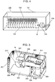
- Fig. 4 is a configuration diagram of an air conditioner in accordance with the second exemplary embodiment of the present invention.
- an air conditioner installed indoors as an indoor unit is described as an example of an electric device of the present invention.
- air conditioner 100 includes heat exchanger 102, fan 103, and electric motor 104 of the first exemplary embodiment in housing 101.
- Heat exchanger 102 is configured so as to include a conductive metal member, and performs heat exchange of the air having taken in from a suction part for cooling and heating.
- Fan 103 is a cross flow fan, and blows the air conditioned by heat exchanger 102.
- Electric motor 104 is connected to fan 103 via rotating shaft 16 of electric motor 104, and rotary-drives fan 103. With such a configuration of air conditioner 100, the air conditioned by heat exchanger 102 is blown by rotation of fan 103 into the room, for example.
- air conditioner 100 includes electric motor 104 of the first exemplary embodiment. Particularly when electric motor 104 is used in air conditioner 100 as an indoor unit, high-frequency signals generated in stator iron core 11 are likely to be transferred from rotating body 30 via rotating shaft 16 to fan 103. The signals are further transferred from fan 103 to heat exchanger 102 in some cases. In the case of air conditioner 100 as such an indoor unit, fan 103 and heat exchanger 102 have large areas and volumes, and thus high-frequency signals transferred to these elements are likely to radiate as unnecessary signals and the radiated signals can go into bearings 15 and affect the shaft voltage.
- dielectric layer 50 works as an impedance component series-connected between stator iron core 11 and fan 103, and thus can attenuate high-frequency signals transferred to fan 103. That is, this configuration can also suppress the shaft voltage caused by unnecessary radiation from fan 103 and heat exchanger 102.
- air conditioner outdoor unit 301 includes electric motor 104 of the first exemplary embodiment inside housing 311.
- Electric motor 104 has fan 312 attached to rotating shaft 16, and functions as a blower electric motor.
- Air conditioner outdoor unit 301 is partitioned into compressor chamber 306 and heat-exchanger chamber 309 by partition plate 304 standing on base plate 302 of housing 311.
- Compressor 305 is disposed in compressor chamber 306.
- Heat exchanger 307 and the blower electric motor are disposed in heat-exchanger chamber 309.
- Electrical component box 310 is disposed on partition plate 304.
- blower electric motor fan 312 is rotated by rotation of electric motor 104 that is driven by motor drive unit 303 housed in electrical component box 310. Then, the blower electric motor blows air through heat exchanger 307 into heat-exchanger chamber 309.
- the electric device of the present invention includes an electric motor, and a housing including the electric motor.
- the electric device uses the electric motor of the present invention configured as above.
- This configuration can prevent misalignment of the outer iron core, the dielectric layer, and the inner iron core of the rotor caused by rotation, keep the balance in impedance between the stator side and the rotor side, and reduce a shaft voltage without reducing the efficiency of the motor.
- the electric potential difference between the outer ring and the inner ring of each bearing, i.e. the shaft voltage can be suppressed extremely low, and thereby occurrence of electrolytic corrosion can be suppressed. Therefore, the present invention can provide an electric motor where electrolytic corrosion in bearings is suppressed, and an electric device including the electric motor.
- the above description shows the indoor unit and the outdoor unit of an air conditioner, as examples of the electric devices of the present invention.
- the present invention can be used in other electric devices, such as a hot water supplier, an air clearer, and a washing machine.
- the shaft voltage in the motor can be reduced and thus occurrence of electrolytic corrosion in the bearing is optimally suppressed.
- the present invention is effective for the indoor unit of an air conditioner, for example.
Landscapes
- Engineering & Computer Science (AREA)
- Power Engineering (AREA)
- Motor Or Generator Frames (AREA)
- Permanent Field Magnets Of Synchronous Machinery (AREA)
- Insulation, Fastening Of Motor, Generator Windings (AREA)
- Iron Core Of Rotating Electric Machines (AREA)
Claims (8)
- Elektromotor (104), der aufweist,
einen Stator (10), der eine Statorwicklung (12) aufweist, die um bzw. auf einen Statoreisenkern (11) gewickelt ist;
einen Rotor (14), der einschließt:einen rotierenden Körper (30), der dem Stator (10) gegenüberliegt und Magnete (32) hält; undeinen Rotationsschaft (16), der den rotierenden Körper (30) dazu befestigt aufweist, um so durch ein Zentrum des rotierenden Körpers (30) hindurch zu gehen bzw. gelangen oder dieses zu penetrieren;ein Lager (15), um den Rotationsschaft (16) einzusetzen bzw. zu lagern; undzwei leitfähige Klammern (17, 19), um das Lager (15) zu fixieren,wobei der rotierende Körper (30) aus einem äußeren Eisenkern (31a), der die äußere Peripherie des rotierenden Körpers (30) ausbildet, einem inneren Eisenkern (31b), der die innere Peripherie ausbildet, die an den Schaft (16) befestigt ist, und einer dielektrischen Schicht (50) ausgebildet ist, wobei die dielektrische Schicht zwischen dem inneren Eisenkern (31b) und dem äußeren Eisenkern (31a) angeordnet ist, um so zwischen dem inneren Eisenkern (31b) und dem äußeren Eisenkern (31a) elektrisch zu isolieren und zu separieren bzw. zu trennen,dadurch gekennzeichnet dass,die dielektrische Schicht (50) eine Polygonform mit dem Rotationsschaft (16) an einem Zentrum davon hat,eine Anzahl der Ecken des Polygons der dielektrischen Schicht (50) gleich zu einer Anzahl magnetisierter Pole der Magneten (32) ist, die in dem rotierenden Körper (30) gehalten sind; undder rotierende Körper (30) eine Vielzahl von Einfügungslöchern (33) hat, die durch den äußeren Eisenkern (31b) hindurchpenetrieren bzw. hindurchgelangen, der an einer äußeren Peripherieseite der dielektrischen Schicht (50) angeordnet ist, und die Magneten in jedem der Einfügungslöcher (33) eingefügt sind;wobei jede Ecke bzw. Vertex des Polygons der dielektrischen Schicht (50) korrespondierend zu einem Zentrum zwischen Polen platziert ist, die in dem Magnet (32) magnetisiert sind, der in dem rotierenden Körper (30) gehalten wird, und zwar mit dem Rotationsschaft (16) in der Mitte bzw. bei oder an dem Zentrum. - Elektromotor (104) nach Anspruch 1, wobei jede Ecke des Polygons der dielektrischen Schicht (50) als eine gerundete Form bzw. in einer gerundeten Form ausgebildet ist.
- Elektromotor (104) nach Anspruch 1, wobei die dielektrische Schicht (50) zumindest den Magneten (32) auf beiden Seiten des rotierenden Körpers (30) in einer axialen Richtung abdeckt.
- Elektromotor (104) nach Anspruch 1, wobei die zwei Klammern (17, 19) miteinander elektrisch verbunden sind.
- Elektromotor (104) nach Anspruch 1, wobei der Statoreisenkern (11) geerdet ist.
- Elektromotor (104) nach Anspruch 1, wobei die zwei Klammern (17, 19), die elektrisch miteinander verbunden sind, und der Statoreisenkern (11) geerdet sind.
- Elektromotor (104) nach Anspruch 1, wobei die Statorwicklung (12), die an dem bzw. um den Statoreisenkern (11) gewickelt ist, durch einen Inverter eines Pulsbreitenmodulationssystems getrieben bzw. angetrieben ist.
- Elektrovorrichtung, die den Elektromotor (104) nach irgendeinem der Ansprüche 1 bis 7 aufweist.
Applications Claiming Priority (2)
| Application Number | Priority Date | Filing Date | Title |
|---|---|---|---|
| JP2011048703 | 2011-03-07 | ||
| PCT/JP2012/001338 WO2012120828A1 (ja) | 2011-03-07 | 2012-02-28 | 電動機およびそれを備えた電気機器 |
Publications (3)
| Publication Number | Publication Date |
|---|---|
| EP2685611A1 EP2685611A1 (de) | 2014-01-15 |
| EP2685611A4 EP2685611A4 (de) | 2014-05-14 |
| EP2685611B1 true EP2685611B1 (de) | 2016-05-25 |
Family
ID=46797803
Family Applications (1)
| Application Number | Title | Priority Date | Filing Date |
|---|---|---|---|
| EP12755764.3A Active EP2685611B1 (de) | 2011-03-07 | 2012-02-28 | Motor und elektrische anlage damit |
Country Status (5)
| Country | Link |
|---|---|
| US (1) | US8546989B2 (de) |
| EP (1) | EP2685611B1 (de) |
| JP (2) | JP5112574B2 (de) |
| CN (1) | CN103155368B (de) |
| WO (1) | WO2012120828A1 (de) |
Cited By (2)
| Publication number | Priority date | Publication date | Assignee | Title |
|---|---|---|---|---|
| US11456648B2 (en) | 2020-04-10 | 2022-09-27 | Delta Electronics, Inc. | Rotor-grounded motor |
| US11545870B2 (en) | 2020-04-10 | 2023-01-03 | Delta Electronics, Inc. | Motor |
Families Citing this family (16)
| Publication number | Priority date | Publication date | Assignee | Title |
|---|---|---|---|---|
| WO2011141957A1 (en) * | 2010-05-12 | 2011-11-17 | Panasonic Corporation | Electric motor and electric device including the same |
| EP2506406B1 (de) * | 2011-03-30 | 2019-09-25 | Fujitsu General Limited | Geformter Motor |
| KR101442414B1 (ko) * | 2013-05-23 | 2014-09-24 | 뉴모텍(주) | 모터 접지구조 |
| CN105264751B (zh) * | 2013-07-04 | 2018-01-16 | 松下知识产权经营株式会社 | 电动机以及具备该电动机的电气设备 |
| JP6208333B2 (ja) | 2014-04-14 | 2017-10-04 | 株式会社日立産機システム | アキシャルギャップ型回転電機 |
| CN103944294B (zh) * | 2014-04-29 | 2017-02-01 | 杭州松下马达有限公司 | 一种马达转子及马达 |
| US10298091B2 (en) * | 2014-10-22 | 2019-05-21 | Mitsubishi Electric Corporation | Rotor of rotating motor, rotating motor, and air-conditioning apparatus |
| CN107852053B (zh) * | 2015-08-05 | 2020-10-23 | 三菱电机株式会社 | 电动机的转子、电动机、送风机以及制冷空调机 |
| JP2017078540A (ja) * | 2015-10-20 | 2017-04-27 | 三菱重工業株式会社 | 室内機、それを備えた空気調和機、及び室内機の組立方法 |
| JP6498315B2 (ja) * | 2015-11-26 | 2019-04-10 | 三菱電機株式会社 | 回転子、モータ、空気調和装置および回転子の製造方法 |
| CN106385121B (zh) * | 2016-10-21 | 2018-10-12 | 沈阳工业大学 | 低损耗组合式径向磁通非晶合金电机 |
| DE102017118125A1 (de) * | 2017-08-09 | 2019-02-14 | Ebm-Papst Mulfingen Gmbh & Co. Kg | Vorrichtung zur Reduzierung von schädlichen Lagerspannungen |
| JP7269663B2 (ja) | 2017-10-10 | 2023-05-09 | ゼロ イー テクノロジーズ,エルエルシー | 電気機械の冷却および安定化システムおよび方法 |
| US20230081655A1 (en) * | 2020-02-28 | 2023-03-16 | Mitsubishi Electric Corporation | Motor, fan, and air conditioner |
| WO2022019074A1 (ja) * | 2020-07-22 | 2022-01-27 | パナソニックIpマネジメント株式会社 | 電動機 |
| JP6937423B1 (ja) * | 2020-12-09 | 2021-09-22 | Wolongモーター制御技術株式会社 | 電動機及びそれを備えた電気機器 |
Family Cites Families (21)
| Publication number | Priority date | Publication date | Assignee | Title |
|---|---|---|---|---|
| US3909647A (en) * | 1973-06-22 | 1975-09-30 | Bendix Corp | Rotor assembly for permanent magnet generator |
| JPS56103938A (en) * | 1980-01-23 | 1981-08-19 | Mitsubishi Electric Corp | Shaft current preventing device for motor |
| JPH07312852A (ja) * | 1994-05-13 | 1995-11-28 | Yaskawa Electric Corp | 永久磁石形回転子の製造方法 |
| US6404086B1 (en) * | 1996-09-13 | 2002-06-11 | Hitachi, Ltd. | Anisotropic magnet brushless motor having a rotor with elastic insulating support structure |
| JP3451396B2 (ja) * | 1999-01-07 | 2003-09-29 | ミネベア株式会社 | ステッピングモータ |
| US6611078B1 (en) * | 2000-07-19 | 2003-08-26 | Tri-Seven Research, Inc. | Flux diode motor |
| US7814641B2 (en) * | 2001-01-09 | 2010-10-19 | Black & Decker Inc. | Method of forming a power tool |
| JP3879413B2 (ja) * | 2001-02-28 | 2007-02-14 | 株式会社日立製作所 | 搬送システム及び回転電機 |
| GB0109847D0 (en) * | 2001-04-21 | 2001-06-13 | Johnson Electric Sa | Motor |
| GB2378323B (en) * | 2001-07-28 | 2005-07-27 | Lg Electronics Inc | Rotor for synchronous reluctance motor and manufacturing method thereof |
| DE10140303A1 (de) * | 2001-08-16 | 2003-02-27 | Bosch Gmbh Robert | Unipolar-Transversalflußmaschine |
| DE10226976A1 (de) * | 2002-06-17 | 2004-03-25 | Siemens Ag | Elektromotor mit einem mehrpoligen Rotor und einem mehrpoligen Stator |
| CA2486453A1 (en) * | 2002-07-12 | 2004-01-22 | Black & Decker Inc. | Dynamoelectric machine having an encapsulated coil structure |
| JP2004274859A (ja) * | 2003-03-07 | 2004-09-30 | Asmo Co Ltd | ロータ及びブラシレスモータ |
| JP5076311B2 (ja) | 2005-12-07 | 2012-11-21 | パナソニック株式会社 | ブラシレスモータ |
| JP4632958B2 (ja) | 2006-01-24 | 2011-02-16 | 三菱電機株式会社 | 空気調和機の放射ノイズ低減装置および空気調和機 |
| US20070228864A1 (en) * | 2006-03-31 | 2007-10-04 | Thingap, Inc. | Wave Winding Armature |
| JP5338641B2 (ja) | 2008-12-03 | 2013-11-13 | パナソニック株式会社 | 電動機およびそれを備えた電気機器 |
| JP5213821B2 (ja) * | 2009-02-04 | 2013-06-19 | 三菱電機株式会社 | 回転電機 |
| JP5227869B2 (ja) * | 2009-03-27 | 2013-07-03 | 株式会社日立産機システム | 電動機 |
| CN102577040B (zh) * | 2009-09-10 | 2013-03-06 | 松下电器产业株式会社 | 电动机和具备它的电气设备 |
-
2012
- 2012-02-28 CN CN201280003301.9A patent/CN103155368B/zh active Active
- 2012-02-28 US US13/808,529 patent/US8546989B2/en active Active
- 2012-02-28 EP EP12755764.3A patent/EP2685611B1/de active Active
- 2012-02-28 WO PCT/JP2012/001338 patent/WO2012120828A1/ja active Application Filing
- 2012-02-28 JP JP2012535491A patent/JP5112574B2/ja active Active
- 2012-09-19 JP JP2012205262A patent/JP2012249522A/ja active Pending
Cited By (2)
| Publication number | Priority date | Publication date | Assignee | Title |
|---|---|---|---|---|
| US11456648B2 (en) | 2020-04-10 | 2022-09-27 | Delta Electronics, Inc. | Rotor-grounded motor |
| US11545870B2 (en) | 2020-04-10 | 2023-01-03 | Delta Electronics, Inc. | Motor |
Also Published As
| Publication number | Publication date |
|---|---|
| JPWO2012120828A1 (ja) | 2014-07-17 |
| CN103155368B (zh) | 2015-07-01 |
| EP2685611A4 (de) | 2014-05-14 |
| WO2012120828A1 (ja) | 2012-09-13 |
| CN103155368A (zh) | 2013-06-12 |
| JP2012249522A (ja) | 2012-12-13 |
| JP5112574B2 (ja) | 2013-01-09 |
| US20130119806A1 (en) | 2013-05-16 |
| EP2685611A1 (de) | 2014-01-15 |
| US8546989B2 (en) | 2013-10-01 |
Similar Documents
| Publication | Publication Date | Title |
|---|---|---|
| EP2685611B1 (de) | Motor und elektrische anlage damit | |
| JP5338641B2 (ja) | 電動機およびそれを備えた電気機器 | |
| JP4957874B2 (ja) | 電動機およびそれを備えた電気機器 | |
| US8987955B2 (en) | Electric motor and electric device including the same | |
| JP5594284B2 (ja) | 電動機およびそれを備えた電気機器 | |
| JP4935934B2 (ja) | 電動機およびそれを備えた電気機器 | |
| JP5110172B2 (ja) | ブラシレスモータおよびそれを備えた電気機器 | |
| JP5370431B2 (ja) | 電動機およびそれを備えた電気機器 | |
| JP5397466B2 (ja) | 電動機およびそれを備えた電気機器 | |
| JP2013066253A (ja) | 電動機およびそれを備えた電気機器 | |
| WO2011043075A1 (ja) | 空気調和機 | |
| WO2011141958A1 (en) | Electric motor and electric device including the electric motor | |
| JP2014107998A (ja) | 電動機 | |
| JP2014018020A (ja) | 電動機およびそれを備えた電気機器 | |
| JP2011205724A (ja) | 空気調和機 | |
| JP5493931B2 (ja) | 空気調和機 | |
| JP2014147241A (ja) | 電動機およびそれを備えた電気機器 | |
| JP2013066252A (ja) | 電動機およびそれを備えた電気機器 | |
| JP2014117110A (ja) | 電動機 |
Legal Events
| Date | Code | Title | Description |
|---|---|---|---|
| PUAI | Public reference made under article 153(3) epc to a published international application that has entered the european phase |
Free format text: ORIGINAL CODE: 0009012 |
|
| 17P | Request for examination filed |
Effective date: 20121126 |
|
| AK | Designated contracting states |
Kind code of ref document: A1 Designated state(s): AL AT BE BG CH CY CZ DE DK EE ES FI FR GB GR HR HU IE IS IT LI LT LU LV MC MK MT NL NO PL PT RO RS SE SI SK SM TR |
|
| REG | Reference to a national code |
Ref country code: DE Ref legal event code: R079 Ref document number: 602012018981 Country of ref document: DE Free format text: PREVIOUS MAIN CLASS: H02K0005160000 Ipc: H02K0001270000 |
|
| RIC1 | Information provided on ipc code assigned before grant |
Ipc: H02K 1/27 20060101AFI20140403BHEP Ipc: H02K 11/00 20060101ALI20140403BHEP Ipc: H02K 5/173 20060101ALI20140403BHEP |
|
| A4 | Supplementary search report drawn up and despatched |
Effective date: 20140411 |
|
| DAX | Request for extension of the european patent (deleted) | ||
| 17Q | First examination report despatched |
Effective date: 20150128 |
|
| GRAP | Despatch of communication of intention to grant a patent |
Free format text: ORIGINAL CODE: EPIDOSNIGR1 |
|
| INTG | Intention to grant announced |
Effective date: 20151214 |
|
| GRAS | Grant fee paid |
Free format text: ORIGINAL CODE: EPIDOSNIGR3 |
|
| GRAA | (expected) grant |
Free format text: ORIGINAL CODE: 0009210 |
|
| AK | Designated contracting states |
Kind code of ref document: B1 Designated state(s): AL AT BE BG CH CY CZ DE DK EE ES FI FR GB GR HR HU IE IS IT LI LT LU LV MC MK MT NL NO PL PT RO RS SE SI SK SM TR |
|
| REG | Reference to a national code |
Ref country code: GB Ref legal event code: FG4D |
|
| REG | Reference to a national code |
Ref country code: CH Ref legal event code: EP |
|
| REG | Reference to a national code |
Ref country code: IE Ref legal event code: FG4D Ref country code: AT Ref legal event code: REF Ref document number: 803048 Country of ref document: AT Kind code of ref document: T Effective date: 20160615 |
|
| REG | Reference to a national code |
Ref country code: DE Ref legal event code: R096 Ref document number: 602012018981 Country of ref document: DE |
|
| REG | Reference to a national code |
Ref country code: LT Ref legal event code: MG4D |
|
| REG | Reference to a national code |
Ref country code: NL Ref legal event code: MP Effective date: 20160525 |
|
| PG25 | Lapsed in a contracting state [announced via postgrant information from national office to epo] |
Ref country code: NL Free format text: LAPSE BECAUSE OF FAILURE TO SUBMIT A TRANSLATION OF THE DESCRIPTION OR TO PAY THE FEE WITHIN THE PRESCRIBED TIME-LIMIT Effective date: 20160525 Ref country code: NO Free format text: LAPSE BECAUSE OF FAILURE TO SUBMIT A TRANSLATION OF THE DESCRIPTION OR TO PAY THE FEE WITHIN THE PRESCRIBED TIME-LIMIT Effective date: 20160825 Ref country code: FI Free format text: LAPSE BECAUSE OF FAILURE TO SUBMIT A TRANSLATION OF THE DESCRIPTION OR TO PAY THE FEE WITHIN THE PRESCRIBED TIME-LIMIT Effective date: 20160525 Ref country code: LT Free format text: LAPSE BECAUSE OF FAILURE TO SUBMIT A TRANSLATION OF THE DESCRIPTION OR TO PAY THE FEE WITHIN THE PRESCRIBED TIME-LIMIT Effective date: 20160525 |
|
| REG | Reference to a national code |
Ref country code: AT Ref legal event code: MK05 Ref document number: 803048 Country of ref document: AT Kind code of ref document: T Effective date: 20160525 |
|
| PG25 | Lapsed in a contracting state [announced via postgrant information from national office to epo] |
Ref country code: RS Free format text: LAPSE BECAUSE OF FAILURE TO SUBMIT A TRANSLATION OF THE DESCRIPTION OR TO PAY THE FEE WITHIN THE PRESCRIBED TIME-LIMIT Effective date: 20160525 Ref country code: SE Free format text: LAPSE BECAUSE OF FAILURE TO SUBMIT A TRANSLATION OF THE DESCRIPTION OR TO PAY THE FEE WITHIN THE PRESCRIBED TIME-LIMIT Effective date: 20160525 Ref country code: GR Free format text: LAPSE BECAUSE OF FAILURE TO SUBMIT A TRANSLATION OF THE DESCRIPTION OR TO PAY THE FEE WITHIN THE PRESCRIBED TIME-LIMIT Effective date: 20160826 Ref country code: PT Free format text: LAPSE BECAUSE OF FAILURE TO SUBMIT A TRANSLATION OF THE DESCRIPTION OR TO PAY THE FEE WITHIN THE PRESCRIBED TIME-LIMIT Effective date: 20160926 Ref country code: ES Free format text: LAPSE BECAUSE OF FAILURE TO SUBMIT A TRANSLATION OF THE DESCRIPTION OR TO PAY THE FEE WITHIN THE PRESCRIBED TIME-LIMIT Effective date: 20160525 Ref country code: LV Free format text: LAPSE BECAUSE OF FAILURE TO SUBMIT A TRANSLATION OF THE DESCRIPTION OR TO PAY THE FEE WITHIN THE PRESCRIBED TIME-LIMIT Effective date: 20160525 |
|
| PG25 | Lapsed in a contracting state [announced via postgrant information from national office to epo] |
Ref country code: IT Free format text: LAPSE BECAUSE OF FAILURE TO SUBMIT A TRANSLATION OF THE DESCRIPTION OR TO PAY THE FEE WITHIN THE PRESCRIBED TIME-LIMIT Effective date: 20160525 |
|
| PG25 | Lapsed in a contracting state [announced via postgrant information from national office to epo] |
Ref country code: RO Free format text: LAPSE BECAUSE OF FAILURE TO SUBMIT A TRANSLATION OF THE DESCRIPTION OR TO PAY THE FEE WITHIN THE PRESCRIBED TIME-LIMIT Effective date: 20160525 Ref country code: SK Free format text: LAPSE BECAUSE OF FAILURE TO SUBMIT A TRANSLATION OF THE DESCRIPTION OR TO PAY THE FEE WITHIN THE PRESCRIBED TIME-LIMIT Effective date: 20160525 Ref country code: DK Free format text: LAPSE BECAUSE OF FAILURE TO SUBMIT A TRANSLATION OF THE DESCRIPTION OR TO PAY THE FEE WITHIN THE PRESCRIBED TIME-LIMIT Effective date: 20160525 Ref country code: CZ Free format text: LAPSE BECAUSE OF FAILURE TO SUBMIT A TRANSLATION OF THE DESCRIPTION OR TO PAY THE FEE WITHIN THE PRESCRIBED TIME-LIMIT Effective date: 20160525 Ref country code: EE Free format text: LAPSE BECAUSE OF FAILURE TO SUBMIT A TRANSLATION OF THE DESCRIPTION OR TO PAY THE FEE WITHIN THE PRESCRIBED TIME-LIMIT Effective date: 20160525 |
|
| PG25 | Lapsed in a contracting state [announced via postgrant information from national office to epo] |
Ref country code: PL Free format text: LAPSE BECAUSE OF FAILURE TO SUBMIT A TRANSLATION OF THE DESCRIPTION OR TO PAY THE FEE WITHIN THE PRESCRIBED TIME-LIMIT Effective date: 20160525 Ref country code: SM Free format text: LAPSE BECAUSE OF FAILURE TO SUBMIT A TRANSLATION OF THE DESCRIPTION OR TO PAY THE FEE WITHIN THE PRESCRIBED TIME-LIMIT Effective date: 20160525 Ref country code: AT Free format text: LAPSE BECAUSE OF FAILURE TO SUBMIT A TRANSLATION OF THE DESCRIPTION OR TO PAY THE FEE WITHIN THE PRESCRIBED TIME-LIMIT Effective date: 20160525 Ref country code: BE Free format text: LAPSE BECAUSE OF FAILURE TO SUBMIT A TRANSLATION OF THE DESCRIPTION OR TO PAY THE FEE WITHIN THE PRESCRIBED TIME-LIMIT Effective date: 20160525 |
|
| REG | Reference to a national code |
Ref country code: DE Ref legal event code: R097 Ref document number: 602012018981 Country of ref document: DE |
|
| PLBE | No opposition filed within time limit |
Free format text: ORIGINAL CODE: 0009261 |
|
| STAA | Information on the status of an ep patent application or granted ep patent |
Free format text: STATUS: NO OPPOSITION FILED WITHIN TIME LIMIT |
|
| 26N | No opposition filed |
Effective date: 20170228 |
|
| PG25 | Lapsed in a contracting state [announced via postgrant information from national office to epo] |
Ref country code: SI Free format text: LAPSE BECAUSE OF FAILURE TO SUBMIT A TRANSLATION OF THE DESCRIPTION OR TO PAY THE FEE WITHIN THE PRESCRIBED TIME-LIMIT Effective date: 20160525 |
|
| PG25 | Lapsed in a contracting state [announced via postgrant information from national office to epo] |
Ref country code: MC Free format text: LAPSE BECAUSE OF FAILURE TO SUBMIT A TRANSLATION OF THE DESCRIPTION OR TO PAY THE FEE WITHIN THE PRESCRIBED TIME-LIMIT Effective date: 20160525 |
|
| REG | Reference to a national code |
Ref country code: CH Ref legal event code: PL |
|
| GBPC | Gb: european patent ceased through non-payment of renewal fee |
Effective date: 20170228 |
|
| PG25 | Lapsed in a contracting state [announced via postgrant information from national office to epo] |
Ref country code: LI Free format text: LAPSE BECAUSE OF NON-PAYMENT OF DUE FEES Effective date: 20170228 Ref country code: CH Free format text: LAPSE BECAUSE OF NON-PAYMENT OF DUE FEES Effective date: 20170228 |
|
| REG | Reference to a national code |
Ref country code: IE Ref legal event code: MM4A |
|
| REG | Reference to a national code |
Ref country code: FR Ref legal event code: ST Effective date: 20171031 |
|
| PG25 | Lapsed in a contracting state [announced via postgrant information from national office to epo] |
Ref country code: LU Free format text: LAPSE BECAUSE OF NON-PAYMENT OF DUE FEES Effective date: 20170228 |
|
| PG25 | Lapsed in a contracting state [announced via postgrant information from national office to epo] |
Ref country code: FR Free format text: LAPSE BECAUSE OF NON-PAYMENT OF DUE FEES Effective date: 20170228 |
|
| PG25 | Lapsed in a contracting state [announced via postgrant information from national office to epo] |
Ref country code: IE Free format text: LAPSE BECAUSE OF NON-PAYMENT OF DUE FEES Effective date: 20170228 Ref country code: GB Free format text: LAPSE BECAUSE OF NON-PAYMENT OF DUE FEES Effective date: 20170228 |
|
| PG25 | Lapsed in a contracting state [announced via postgrant information from national office to epo] |
Ref country code: MT Free format text: LAPSE BECAUSE OF NON-PAYMENT OF DUE FEES Effective date: 20170228 |
|
| PG25 | Lapsed in a contracting state [announced via postgrant information from national office to epo] |
Ref country code: AL Free format text: LAPSE BECAUSE OF FAILURE TO SUBMIT A TRANSLATION OF THE DESCRIPTION OR TO PAY THE FEE WITHIN THE PRESCRIBED TIME-LIMIT Effective date: 20160525 |
|
| PG25 | Lapsed in a contracting state [announced via postgrant information from national office to epo] |
Ref country code: HU Free format text: LAPSE BECAUSE OF FAILURE TO SUBMIT A TRANSLATION OF THE DESCRIPTION OR TO PAY THE FEE WITHIN THE PRESCRIBED TIME-LIMIT; INVALID AB INITIO Effective date: 20120228 |
|
| PG25 | Lapsed in a contracting state [announced via postgrant information from national office to epo] |
Ref country code: BG Free format text: LAPSE BECAUSE OF FAILURE TO SUBMIT A TRANSLATION OF THE DESCRIPTION OR TO PAY THE FEE WITHIN THE PRESCRIBED TIME-LIMIT Effective date: 20160525 |
|
| PG25 | Lapsed in a contracting state [announced via postgrant information from national office to epo] |
Ref country code: CY Free format text: LAPSE BECAUSE OF NON-PAYMENT OF DUE FEES Effective date: 20160525 |
|
| PG25 | Lapsed in a contracting state [announced via postgrant information from national office to epo] |
Ref country code: MK Free format text: LAPSE BECAUSE OF FAILURE TO SUBMIT A TRANSLATION OF THE DESCRIPTION OR TO PAY THE FEE WITHIN THE PRESCRIBED TIME-LIMIT Effective date: 20160525 |
|
| PG25 | Lapsed in a contracting state [announced via postgrant information from national office to epo] |
Ref country code: TR Free format text: LAPSE BECAUSE OF FAILURE TO SUBMIT A TRANSLATION OF THE DESCRIPTION OR TO PAY THE FEE WITHIN THE PRESCRIBED TIME-LIMIT Effective date: 20160525 |
|
| PG25 | Lapsed in a contracting state [announced via postgrant information from national office to epo] |
Ref country code: HR Free format text: LAPSE BECAUSE OF FAILURE TO SUBMIT A TRANSLATION OF THE DESCRIPTION OR TO PAY THE FEE WITHIN THE PRESCRIBED TIME-LIMIT Effective date: 20160525 |
|
| PG25 | Lapsed in a contracting state [announced via postgrant information from national office to epo] |
Ref country code: IS Free format text: LAPSE BECAUSE OF FAILURE TO SUBMIT A TRANSLATION OF THE DESCRIPTION OR TO PAY THE FEE WITHIN THE PRESCRIBED TIME-LIMIT Effective date: 20160925 |
|
| PGFP | Annual fee paid to national office [announced via postgrant information from national office to epo] |
Ref country code: DE Payment date: 20240219 Year of fee payment: 13 |