EP2685591B1 - Batterieverwaltungseinheit für ein Fahrzeug - Google Patents
Batterieverwaltungseinheit für ein Fahrzeug Download PDFInfo
- Publication number
- EP2685591B1 EP2685591B1 EP13175428.5A EP13175428A EP2685591B1 EP 2685591 B1 EP2685591 B1 EP 2685591B1 EP 13175428 A EP13175428 A EP 13175428A EP 2685591 B1 EP2685591 B1 EP 2685591B1
- Authority
- EP
- European Patent Office
- Prior art keywords
- cell
- voltage
- battery
- cells
- voltages
- Prior art date
- Legal status (The legal status is an assumption and is not a legal conclusion. Google has not performed a legal analysis and makes no representation as to the accuracy of the status listed.)
- Active
Links
Images


Classifications
-
- B—PERFORMING OPERATIONS; TRANSPORTING
- B60—VEHICLES IN GENERAL
- B60L—PROPULSION OF ELECTRICALLY-PROPELLED VEHICLES; SUPPLYING ELECTRIC POWER FOR AUXILIARY EQUIPMENT OF ELECTRICALLY-PROPELLED VEHICLES; ELECTRODYNAMIC BRAKE SYSTEMS FOR VEHICLES IN GENERAL; MAGNETIC SUSPENSION OR LEVITATION FOR VEHICLES; MONITORING OPERATING VARIABLES OF ELECTRICALLY-PROPELLED VEHICLES; ELECTRIC SAFETY DEVICES FOR ELECTRICALLY-PROPELLED VEHICLES
- B60L53/00—Methods of charging batteries, specially adapted for electric vehicles; Charging stations or on-board charging equipment therefor; Exchange of energy storage elements in electric vehicles
-
- B—PERFORMING OPERATIONS; TRANSPORTING
- B60—VEHICLES IN GENERAL
- B60L—PROPULSION OF ELECTRICALLY-PROPELLED VEHICLES; SUPPLYING ELECTRIC POWER FOR AUXILIARY EQUIPMENT OF ELECTRICALLY-PROPELLED VEHICLES; ELECTRODYNAMIC BRAKE SYSTEMS FOR VEHICLES IN GENERAL; MAGNETIC SUSPENSION OR LEVITATION FOR VEHICLES; MONITORING OPERATING VARIABLES OF ELECTRICALLY-PROPELLED VEHICLES; ELECTRIC SAFETY DEVICES FOR ELECTRICALLY-PROPELLED VEHICLES
- B60L58/00—Methods or circuit arrangements for monitoring or controlling batteries or fuel cells, specially adapted for electric vehicles
- B60L58/10—Methods or circuit arrangements for monitoring or controlling batteries or fuel cells, specially adapted for electric vehicles for monitoring or controlling batteries
- B60L58/18—Methods or circuit arrangements for monitoring or controlling batteries or fuel cells, specially adapted for electric vehicles for monitoring or controlling batteries of two or more battery modules
- B60L58/22—Balancing the charge of battery modules
-
- H—ELECTRICITY
- H02—GENERATION; CONVERSION OR DISTRIBUTION OF ELECTRIC POWER
- H02J—ELECTRIC POWER NETWORKS; CIRCUIT ARRANGEMENTS OR SYSTEMS FOR SUPPLYING OR DISTRIBUTING ELECTRIC POWER; SYSTEMS FOR STORING ELECTRIC ENERGY
- H02J7/00—Circuit arrangements for charging or discharging batteries or for supplying loads from batteries
- H02J7/50—Circuit arrangements for charging or discharging batteries or for supplying loads from batteries acting upon multiple batteries simultaneously or sequentially
- H02J7/52—Circuit arrangements for charging or discharging batteries or for supplying loads from batteries acting upon multiple batteries simultaneously or sequentially for charge balancing, e.g. equalisation of charge between batteries
- H02J7/54—Passive balancing, e.g. using resistors or parallel MOSFETs
-
- H—ELECTRICITY
- H01—ELECTRIC ELEMENTS
- H01M—PROCESSES OR MEANS, e.g. BATTERIES, FOR THE DIRECT CONVERSION OF CHEMICAL ENERGY INTO ELECTRICAL ENERGY
- H01M10/00—Secondary cells; Manufacture thereof
- H01M10/42—Methods or arrangements for servicing or maintenance of secondary cells or secondary half-cells
- H01M10/44—Methods for charging or discharging
- H01M10/441—Methods for charging or discharging for several batteries or cells simultaneously or sequentially
-
- H—ELECTRICITY
- H01—ELECTRIC ELEMENTS
- H01M—PROCESSES OR MEANS, e.g. BATTERIES, FOR THE DIRECT CONVERSION OF CHEMICAL ENERGY INTO ELECTRICAL ENERGY
- H01M10/00—Secondary cells; Manufacture thereof
- H01M10/42—Methods or arrangements for servicing or maintenance of secondary cells or secondary half-cells
- H01M10/44—Methods for charging or discharging
- H01M10/446—Initial charging measures
-
- H—ELECTRICITY
- H01—ELECTRIC ELEMENTS
- H01M—PROCESSES OR MEANS, e.g. BATTERIES, FOR THE DIRECT CONVERSION OF CHEMICAL ENERGY INTO ELECTRICAL ENERGY
- H01M10/00—Secondary cells; Manufacture thereof
- H01M10/42—Methods or arrangements for servicing or maintenance of secondary cells or secondary half-cells
- H01M10/44—Methods for charging or discharging
- H01M10/448—End of discharge regulating measures
-
- Y—GENERAL TAGGING OF NEW TECHNOLOGICAL DEVELOPMENTS; GENERAL TAGGING OF CROSS-SECTIONAL TECHNOLOGIES SPANNING OVER SEVERAL SECTIONS OF THE IPC; TECHNICAL SUBJECTS COVERED BY FORMER USPC CROSS-REFERENCE ART COLLECTIONS [XRACs] AND DIGESTS
- Y02—TECHNOLOGIES OR APPLICATIONS FOR MITIGATION OR ADAPTATION AGAINST CLIMATE CHANGE
- Y02E—REDUCTION OF GREENHOUSE GAS [GHG] EMISSIONS, RELATED TO ENERGY GENERATION, TRANSMISSION OR DISTRIBUTION
- Y02E60/00—Enabling technologies; Technologies with a potential or indirect contribution to GHG emissions mitigation
- Y02E60/10—Energy storage using batteries
-
- Y—GENERAL TAGGING OF NEW TECHNOLOGICAL DEVELOPMENTS; GENERAL TAGGING OF CROSS-SECTIONAL TECHNOLOGIES SPANNING OVER SEVERAL SECTIONS OF THE IPC; TECHNICAL SUBJECTS COVERED BY FORMER USPC CROSS-REFERENCE ART COLLECTIONS [XRACs] AND DIGESTS
- Y02—TECHNOLOGIES OR APPLICATIONS FOR MITIGATION OR ADAPTATION AGAINST CLIMATE CHANGE
- Y02T—CLIMATE CHANGE MITIGATION TECHNOLOGIES RELATED TO TRANSPORTATION
- Y02T10/00—Road transport of goods or passengers
- Y02T10/60—Other road transportation technologies with climate change mitigation effect
- Y02T10/70—Energy storage systems for electromobility, e.g. batteries
-
- Y—GENERAL TAGGING OF NEW TECHNOLOGICAL DEVELOPMENTS; GENERAL TAGGING OF CROSS-SECTIONAL TECHNOLOGIES SPANNING OVER SEVERAL SECTIONS OF THE IPC; TECHNICAL SUBJECTS COVERED BY FORMER USPC CROSS-REFERENCE ART COLLECTIONS [XRACs] AND DIGESTS
- Y02—TECHNOLOGIES OR APPLICATIONS FOR MITIGATION OR ADAPTATION AGAINST CLIMATE CHANGE
- Y02T—CLIMATE CHANGE MITIGATION TECHNOLOGIES RELATED TO TRANSPORTATION
- Y02T10/00—Road transport of goods or passengers
- Y02T10/60—Other road transportation technologies with climate change mitigation effect
- Y02T10/7072—Electromobility specific charging systems or methods for batteries, ultracapacitors, supercapacitors or double-layer capacitors
-
- Y—GENERAL TAGGING OF NEW TECHNOLOGICAL DEVELOPMENTS; GENERAL TAGGING OF CROSS-SECTIONAL TECHNOLOGIES SPANNING OVER SEVERAL SECTIONS OF THE IPC; TECHNICAL SUBJECTS COVERED BY FORMER USPC CROSS-REFERENCE ART COLLECTIONS [XRACs] AND DIGESTS
- Y02—TECHNOLOGIES OR APPLICATIONS FOR MITIGATION OR ADAPTATION AGAINST CLIMATE CHANGE
- Y02T—CLIMATE CHANGE MITIGATION TECHNOLOGIES RELATED TO TRANSPORTATION
- Y02T90/00—Enabling technologies or technologies with a potential or indirect contribution to GHG emissions mitigation
- Y02T90/10—Technologies relating to charging of electric vehicles
- Y02T90/14—Plug-in electric vehicles
Definitions
- the present invention relates to a battery management unit that controls charging and discharging of an assembled battery mounted on a vehicle.
- one of known techniques balances (equalizes) the voltages of the respective cells when the cells are being used or being charged. Specifically, this technique balances the respective voltages of the cells to reduce the dispersion of voltages (differences of the voltages), aiming at maximizing the battery capacity of the entire assembled battery. Balancing cell voltages while the assembled battery is being charged makes it possible to increase, until the highest voltage of a cell among the multiple cells included in the assembled battery exceeds the upper limit voltage, amounts of electric power charging the remaining cells. Similarly, balancing cell voltages while the assembled battery is being used makes it possible to increase usable electric power of the entire assembled battery. In other words, this can suppress reduction in available battery capacity.
- Patent Literature 1 Japanese Laid-Open Patent Publication No. 2003-309931 .
- the other scheme is to transfer electric power of cells having high voltages to cells having low voltages.
- each of cells is disconnectably connected to a coil which is magnetically coupled with the each other coils.
- Electric power is transferred from cells having high voltages to cells having low voltages using electromagnetic induction (e.g., Patent Literature 2: Japanese Laid-Open Patent Publication No. 2006-166615 ).
- Patent Literature 2 Japanese Laid-Open Patent Publication No. 2006-166615 .
- one or more cells having high voltage among all the cells are detected.
- the voltage of the high-voltage cells is reduced in order to balance (equalize) the voltage of the entire assembled battery.
- Patent Literature 1 specifies a cell having the lowest voltage when the total voltage of the assembled battery is equal to or lower than the target voltage. And the technique controls the time of discharging each remaining cell on the basis of the difference between the voltage of the remaining cell and the lowest-voltage cell.
- Patent Literature 2 monitors voltages of the respective cells at any time and controls a time of activating the voltage balancer circuit on the basis of the difference between the highest voltage and the lowest voltage among the monitored voltages.
- the assembled batteries are used in vehicles in different manners according to the kind of vehicle, and the difference may affect the dispersion of voltages.
- an electric vehicle relatively frequently undergoes external charging and consequently balancing of cell voltages can be carried out each time the vehicle undergoes external charging, so that the dispersion of voltage is less increased.
- the cell-balancing uses electric power from an external power source and therefore can escape from power shortage even if the cell-balancing takes a long time.
- an optimum state of cell voltages can be relatively easily kept.
- a plug-in hybrid vehicle which is capable of charging the assembled battery with electric power generated by the vehicle per se, less frequently undergoes external charging than an electric vehicle.
- cell-balancing performed only when external charging as performed in an electric vehicle does not ensure sufficient frequency of the cell-balancing and therefore has a difficulty in preferably suppressing the dispersion of voltages.
- One solution to ensure sufficient frequency of the cell-balancing is to carry out the cell-balancing also when the vehicle is not undergoing external charging, which forces the vehicle to generate electric power to be consumed during the cell-balancing. Consequently, a longer time that the cell-balancing takes consumes a larger amount of electric power to degrade the fuel efficiency and the electric efficiency.
- the US patent application US2011/234170 discloses a battery management unit comprising an equalizer that carries out equalization by discharging one ore more cells having a voltage higher than a current voltage of a lowest cell.
- a controller samples multiple discharging/ charging cell voltages at predetermined times. Cell voltage differences are then computed between a battery cell having the minimum discharging cell voltage and another battery cell. A differential capacity is then computed based on this difference.
- an object of the present embodiment is to provide a battery management unit for a battery mounted on a vehicle which unit is capable of suppressing the dispersion of voltages when the battery is fully charged and also suppressing increase in the dispersion caused by change in a state of charge.
- the battery management unit for a vehicle disclosed herein includes: a charger (14) mounted on the vehicle (10) for charging an assembled battery (13) including a plurality of cells (9) with electric power from an external power source; and a memory (1) that records which cell is a lowest cell having the lowest voltage when the assembled battery (13) is fully charged among the plurality of cells (9).
- the battery management unit further includes a cell-balancer (5) that carries out cell-balancing on the voltage of the assembled battery (13) by discharging, when the charger (14) is not charging the assembled battery (13), one or more cells (9) each currently having a voltage higher than a current voltage of the lowest cell (9) to the current voltage of the lowest cell (9).
- a cell-balancer (5) that carries out cell-balancing on the voltage of the assembled battery (13) by discharging, when the charger (14) is not charging the assembled battery (13), one or more cells (9) each currently having a voltage higher than a current voltage of the lowest cell (9) to the current voltage of the lowest cell (9).
- the "lowest cell” is a name of what used to have the lowest voltage when the battery was fully charged in the last external charge, for example.
- the memory does not record the lowest voltage at full charge, but record that which cell is a "lowest cell”.
- the current voltage of the "lowest cell” is considered as a target voltage.
- the cell-balancer controls the voltage, which is higher than the current voltage of the "lowest cell", to the target voltage.
- the cell-balancer carries out cell-balancing on the voltages of the plurality of cells on the basis of the current voltage of the lowest cell even if the lowest cell does not have the lowest voltages at the time of carrying out the cell-balancing.
- the cell-balancing of the voltages of the plurality of cells is preferably carried out under a state where the battery has a small load, such as while the vehicle is running or stopping.
- cell-balancer The control carried out by the cell-balancer is also referred to as “equalization”, “voltage equalization”, “balancer control”, “balancing control”, and others.
- cell-balancing here means that to balance or to equalize the voltages of the respective cells (i.e., the plurality of cells).
- the battery management unit may further include a calculator (2) that calculates a cell capacity difference ( ⁇ C) based on the difference between a lowest voltage and a highest voltage among voltages of the plurality of cells (9) when the assembled battery (13) is fully charged; and a setter (3) that sets an upper limit (T MAX ) of cumulative time of carrying out the cell-balancing based on a consumption electric current (I) of the cell-balancing and the cell capacity difference ( ⁇ C) calculated by the calculator (2).
- the cell-balancer (5) may prohibit the cell-balancing from being carried out for cumulative time longer than the upper limit (T MAX ) set by the setter (3).
- the setter (3) resets the upper limit (T MAX ) whenever the assembled battery (13) is fully charged. In other words, when the battery is fully charged under a state where the cell-balancing is prohibited from being carried out for a cumulative time longer than the upper limit, the setter resets the setting so as to allow the cell-balancing to be carried out again.
- the cell-balancer (5) sets the absolute value of charging or discharging electric current being less than a criterional value. Namely, the cell-balancing is carried out only when the electric load on the assembled battery is relatively small.
- balancer control that discharges one or more cells each currently having a voltage higher than an open-circuit voltage (a current voltage) of the lowest cell, which is regarded as a target voltage, to the target voltage is carried out, and thereby the dispersion of battery capacities when the respective cells are fully charged again can be reduced.
- a current voltage open-circuit voltage
- a battery management unit (BMU) 7 of a first embodiment is applied to a vehicle 10 of FIG. 1 .
- the vehicle 10 is a plug-in hybrid vehicle that travels using an engine 11 and a motor 12 in combination with each other.
- a battery 13, which is a power source of the motor 12 is mounted at an arbitrary position of the vehicle 10.
- a battery 13, which is a power source of the motor 12, is mounted at an arbitrary position of the vehicle 10.
- the motor 12 is a motor generator having functions of: using the electric power of the battery 13 to drive the vehicle 10; and generating (regenerating) electric power by using the inertia of the vehicle 10 being running. These two functions are properly controlled in accordance with the running state of the vehicle 10.
- the battery 13 contains multiple battery modules coupled to one another.
- a battery module is an assembled battery formed by coupling many lithium-ion secondary battery cells 9 to one another.
- the cells 9 may be coupled to one another in any manner and similarly, the battery modules may be coupled to one another in any manner. These coupling manners may be serial, parallel, or a combination of serial and parallel, and are determined in accordance with, for example, values of the rated voltage and the rated electric current expected for the battery 13.
- a battery module can be regarded as an assembled battery including multiple cells 9 each being regarded as a unit battery and the battery 13 can be regarded as an assembled battery including multiple cells 9 or battery modules each being regarded as a unit battery.
- the state of charging and discharging of the battery 13 is grasped and managed by the BMU 7, which is an electronic control unit formed of a microcomputer.
- the BMU 7 are a microprocessor, an LSI (large scale integration) device and an embedded electronic device in which a CPU (central processing unit), a ROM (read only memory), and/or a RAM (random access memory) which are known to the public are integrated.
- the battery 13 of the first embodiment is assumed to be chargeable in two methods of: charging with electric power supplied from an external power source; and charging with electric power generated by rotation of the motor 12 or other element. Dispersion of self-discharging characteristics and dispersion of cell capacities may cause the cells 9 included in the battery 13 when being charged to have dispersion of voltages thereof.
- the BMU 7 carries out a cell-balancer control (cell-balancing control, equalization) that balances the voltages of the respective cells 9 included in the battery 13.
- the vehicle 10 includes a charge inlet 14 (electric power inlet, charger) that is an interface to connect the vehicle 10 to a charge cable 15 on the outer surface thereof.
- the charge cable 15 couples the vehicle 10 with a non-illustrated external power source supplier when the battery 13 is to be charged from an external power source.
- external charging charging the battery 13 from an external power source is referred to as external charging".
- the vehicle 10 is coupled to an external power source by plugging a charge cable 15 into the charge inlet 14. Accordingly, the charge inlet 14 and the charge cable 15 collectively function as charging device (charger) that charges the battery 13 with electric power from an external power source.
- charging device charger
- the balancer control carried out while the vehicle 10 is running (including, for example, brief stopping and halting while external charging is not being carried out).
- the balancer control can be of course carried out during external charging.
- FIG. 2 schematically illustrates an example of the configuration of an electric circuit to carry out the balancer control.
- a balancer circuit (equalization circuit) 8 is coupled to each cell 9 included in the battery 13.
- the balancer circuit 8 has a function to change the open-circuit voltage of the cell 9.
- a typical balancer circuit 8 has a resistor bypass circuit that connects the electrodes of the cell 9 to each other.
- Each balancer circuit 8 includes a circuit element 16, a resistor 17, and a switch 18 that are disposed between the both electrodes of the corresponding cell 9, and a voltage obtainer 19.
- the resistor 17, and the switch 18 are serially interposed in the circuit element 16.
- the resistor 17 consumes electric power stored in the corresponding cell 9 by converting the electric power to heat.
- the switch 18 opens and closes in accordance with the state of storing electric power in the corresponding cell 9 and thereby controls the state of electric current passing through the circuit element 16.
- a control line 21 which switches the open/close state (on/off state) of the switch 18 is disposed between the BMU 7 and the switch 18.
- the voltage obtainer 19 detects the open-circuit voltage (non-loaded voltage) of the corresponding cell 9.
- the open-circuit voltage corresponds to a difference of electric potentials between two points sandwiching both resistor 17 and the switch 18 on the circuit element 16 under a state where the cell 9 has no load.
- a open-circuit voltage of a cell 9 is also referred to as a "voltage,".
- the data (information) of the voltage detected by the voltage obtainer 19 is notified to the BMU 7 through a signal line 22.
- the BMU 7 is coupled to the charge inlet 14 via a signal line 23 through which information of a state of electric power supply from the charge cable 15 is notified to the charge inlet 14. Examples of the information that the signal line 23 notifies are whether the electric power is supplied to the charge inlet 14 and whether the charge cable 15 is plugged in the charge inlet 14. On the basis of the information notified through the signal line 23, the BMU 7 determines whether external charging is being carried out.
- the BMU 7 includes a memory 1 (memory unit, memory device), a calculator 2 (calculation unit, calculation device), a setter 3 (setting unit, setting device), a determiner 4 (unit or device of conditional judgment), and a cell-balancer 5 (cell-balancing controller, cell-balancing unit, cell-balancing device, equalizing unit, equalizing device).
- a memory 1 memory unit, memory device
- a calculator 2 calculation unit, calculation device
- a setter 3 setting unit, setting device
- a determiner 4 unit or device of conditional judgment
- cell-balancer 5 cell-balancing controller, cell-balancing unit, cell-balancing device, equalizing unit, equalizing device.
- the memory 1 receives information of the voltages input through the multiple signal lines 22 and stores the information of the voltages in association with the numbers of the cells 9 corresponding to the signal lines 22.
- the respective cells 9 are assigned unique cell numbers #1, #2, ..., #N, and information of the voltages of the respective cells is represented by V 1 , V 2 , ..., V N by using the subscripts of the corresponding cell numbers.
- the memory 1 obtains the real-time information of the voltages of the respective cells 9 and stores the obtained information.
- the memory 1 records which cell is the cell having the lowest voltage when the cells 9 are fully charged upon completion of external charging the battery 13 among the multiple cells 9. For example, if the voltage information V 1 is the lowest when the battery 13 is fully charged, the memory 1 records therein the cell number #1 corresponding to the voltage information V 1 .
- a cell 9 having the lowest voltage when the battery 13 was fully charged is called the "lowest cell”.
- the information of the cell number of the lowest cell is unchanged and retained until the battery 13 comes to be fully charged by the external charging again.
- the "lowest cell” is a name of what used to have the lowest voltage when the battery was fully charged. Therefore, the lowest cell” does not always have a lowest voltage in the battery 13.
- the capacity difference ⁇ C is calculated from a mathematical expression, a map, or other means that expresses the association of a voltage with a battery capacity. The information of the calculated capacity difference ⁇ C is notified to the setter 3.
- the calculator 2 regards a current voltage of the lowest cell, the value being stored in the memory 1, as a target voltage V TGT and calculates the voltage difference ⁇ V Y between the maximum voltage V YMAX among the current value of voltages of the cells 9 and the target voltage V TGT .
- the target voltage V TGT is a current voltage of a cell 9 that used to have the lowest voltage when the battery 13 was fully charged.
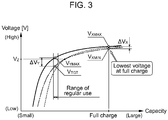
- the target voltage V TGT is not always the lowest among the current voltages (at the time) of all the cells 9. For example, as illustrated in the graph of FIG.
- a voltage at which the broken line crosses the chain line is called the intersection voltage V z .
- the target voltage V TGT is not the lowest at the time.
- the batteries 13 of some hybrid vehicles are set the target capacity (target charging rate) while the vehicle 10 is running to be around 50 %, there is a possibility that a cell 9 is repeatedly used in the voltage region lower than the intersection voltage V z .
- the calculator 2 still regards the current voltage of the lowest cell as the target voltage V TGT .
- the information of the voltage difference ⁇ V Y calculated by the calculator 2 is notified to the determiner 4.
- the setter 3 sets an allowable time T MAX of balancer control on the basis of an operational electric current I of the balancer circuit 8 and the capacity difference ⁇ C calculated by the calculator 2.
- the operational electric current I of the balancer circuit 8 is an electric current that passes through the resistor 17 when the switch 18 is turned on.
- the allowable time T MAX of balancer control is the upper limit of a cumulative time of activating the balancer circuit 8. In other words, allowable time T MAX is the upper limit of a cumulative time T of carrying out the balancer control.
- the allowable time T MAX set by the setter 3 is notified to the cell-balancer 5.
- the determiner 4 determines whether various conditions to carry out balancer control are each satisfied, the balancer control which is performed by balancing (equalizing) the voltages of the cells 9 by activating the balancer circuits 8. Here, when all the following Conditions 1-4 are satisfied, the determiner 4 determines that the condition to carry out the balancer control is satisfied. On the other hand, when any one of Conditions 1-4 is not satisfied, the determiner 4 determines that the condition to carry out the balancer control is not satisfied. The result of the determination by the determiner 4 is notified to the cell-balancer 5.
- Condition 1 is determined on the basis of the information notified from the charge inlet 14 through the signal line 23. For example, the condition 1 is satisfied when the vehicle 10 is not charged by external source or when the charge cable 15 is not connected to the vehicle 10.
- Condition 2 is to confirm that the battery 13 is not being used or that, even if the battery 13 is being used, the battery 13 has a relatively small amount of charging or discharging per unit time. If the amount of charging or discharging the battery 13 is relatively large (that is, a large amount of electric power of the battery 13 is being consumed or an amount of electric power being regenerated is large), it is difficult to obtain exact open-circuit voltages of the respective cells 9 to further make it difficult to improve the accuracy the balancer control.
- the exact open-circuit voltages of the respective cells 9 can be obtained to further enhance the accuracy control of the balancer circuits 8.
- the amount of charging or discharging the battery 13 may be based on an amount of decline in voltage of the battery 13 or a charging or discharging electric current of the battery 13.
- the electric load on the battery 13 is determined to be small when the absolute value of an electric current charging or discharging the battery 13 is less than a certain, criterional electric current value.
- Condition 3 is determined by comparing the voltage difference ⁇ V Y calculated by the calculator 2 with a criterional voltage difference ⁇ V TH .
- the criterional voltage difference ⁇ V TH may be a fixed value given in advance according to the characteristics and/or the kind of the battery 13, or may be a variable set on the basis of the accumulated time of using the battery 13 or a charging ratio of the battery 13 (an average of charging ratios of the respective cells 9, the charging ratio of the lowest cell, state of charge as known as SoC or so on). As illustrated in FIG. 3 , the dispersion of voltages derived from the charging-discharging characteristics of the respective cells 9 tends to increase as the battery capacities of the respective cells 9 reduce.
- Condition 4 is determined by comparing the allowable time T MAX set by the setter 3 and the cumulative time T of carrying out the balancer control actually measured.
- the cumulative time T of carrying out the balancer control is cumulatively measured while the cell-balancer 5 that is to be detailed below carries out the balancer control. According to this condition, the cell-balancer 5 prohibits balancer control from being carried out longer than the allowable time T MAX . In other words, the cumulative time T is not allowed to exceed the allowable time T MAX .
- the cell-balancer 5 (cell-balancing controller) carries out the balancer control, regarding a current voltage of the lowest cell that is stored in the memory 1 as the target value.
- the target voltage V TGT for the balancer control of the first embodiment is not the lowest voltage at the time point of the control, but is the voltage of the lowest cell at the same time point. Accordingly, if a cell 9 has a voltage lower than the target voltage V TGT as illustrated in FIG. 3 , the cell-balancer 5 excludes the cell 9 having lower voltages from the balancer control. This means that the balancer control is to be carried out on the cells 9 having higher voltages than the current voltage of the lowest cell at the time.
- the cell-balancer 5 When the determiner 4 determines that the condition to carry out the balancer control is satisfied, the cell-balancer 5 outputs an "on" signal to the switches 18 of the cells 9 which currently have voltages higher than the target voltage V TGT to activate the respective balancer circuits 8.
- the cell-balancer 5 has a function of balancing the battery voltage by discharging the cells 9 having higher voltages than the target voltage V TGT .
- the cell-balancer 5 measures the cumulative time T of activating any balancer circuit 8 and notifies the measured cumulative time T to the determiner 4.
- the determiner 4 uses the information of the measured cumulative time T for determination on the above Condition 4. After the measured cumulative time T of carrying out the balancer control reaches the allowable time T MAX , Condition 4 comes to be unsatisfied and the balancer control is not carried out any longer.
- the measured value of the cumulative time T of carrying out the balancer control is reset to zero each time the setter 3 sets a new allowable time T MAX . This means that the cumulative time T is reset whenever the battery 13 comes to be fully charged as a result of external charging.
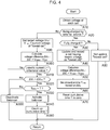
- FIG. 4 is a flow diagram illustrating a succession of procedural steps of the balancer control carried out in the BMU 7.
- the procedural steps of this flow diagram are repeated at certain intervals (e.g., at a cycle of several dozen milliseconds).
- balancer control may be of course carried out during external charging.
- step A10 information of the open-circuit voltages of the respective cells 9 is input into the BMU 7 through the multiple signal lines 22 and is stored in the memory 1.
- step A20 the determiner 4 determines, on the basis of the information notified from the charge inlet 14 through the signal line 23, whether the vehicle 10 is being subjected to external charging. This determination in step A20 corresponds to the above Condition 1. If the external charging is being carried out, the procedure proceeds to step A30 while if the external charging is not being carried out, the procedure proceeds to step A90.
- step A30 determination is made as to whether the battery 13 is in the state of being fully charged on the basis of information of the voltages of the respective cells 9 in, for example, the memory 1 and/or the calculator 2. If the battery 13 is determined to be in the fully-charged state, the procedure proceeds to step A40 and one of the cells 9 which has the lowest voltage is recorded to be the lowest cell". At this time, if another cell has been recorded to be the lowest cell already, the information of the lowest cell is updated and stored in the memory 1. In the next step A50, the calculator 2 extracts information corresponding to the lowest voltage V XMIN and the highest voltage V XMAX from the information of the current voltages of the cells 9 stored in the memory 1 and then calculates the voltage difference ⁇ V X .
- step A60 the calculator 2 calculates the capacity difference ⁇ C corresponding to the voltage difference ⁇ V X calculated in the previous step.
- the setter 3 divides the capacity difference ⁇ C by the operational electric current I of the balancer 8 and sets the quotient to be the allowable time T MAX of balancer control.
- the cell-balancer 5 resets the cumulative time T of the balancer control to zero and terminates the corresponding series of procedural steps. If the battery 13 is determined not to be in the fully-charged state in step A30, the procedure proceeds to step A80 and the information of the lowest cell (i.e., the cell number thereof) is not updated and still held.
- step A20 determines in step A20 that the external charging is not being carried out
- the procedure proceeds to step A90.
- the calculator 2 sets the current voltage that the lowest cell" recorded in step A40 has at the time to be the target voltage V TGT .
- the calculator 2 calculates the voltage difference ⁇ V Y between the current highest voltage V YMAX and the target voltage V TGT .
- step A110 the determiner 4 determines whether the absolute value of the charging or discharging electric current of the battery 13 is less than a criterional electric current value.
- This determination in step A110 corresponds to Condition 2.
- the determiner 4 determines that the battery 13 has small electric load and the procedure proceeds to step A120.
- the determiner 4 determines that the battery 13 has large electric load and the condition to carry out the balancer control is not satisfied. Consequently, the procedure proceeds to step A160.
- step A120 the determiner 4 determines whether the voltage difference ⁇ V Y exceeds the criterional voltage difference ⁇ V TH .
- the determination in step A120 corresponds to the above Condition 3. If the voltage difference ⁇ V Y exceeds the criterional voltage difference ⁇ V TH , Condition 3 is satisfied to determine the cells 9 have the large dispersion of voltages and the procedure proceeds to step A130. On the other hand, if Condition 3 is not satisfied, the condition to carry out the balancer control is determined not to be satisfied and the procedure proceeds to step A160.
- step A130 determination is made as to whether the cumulative time T of carrying out the balancer control is less than the allowable time T MAX . This determination in step A130 corresponds to above Condition 4. If the cumulative time T of carrying out the balancer control is less than the allowable time T MAx , Conditions 1-4 are all satisfied so that the condition to carry out the balancer control is satisfied. Consequently, the procedure proceeds to step A140.
- step A140 the cell-balancer 5 outputs an "on" signal to the switches 18 of the cells 9 which currently have voltages higher than the target voltage V TGT and thereby activates the corresponding balancer circuits 8. At this time, the balancer control is not carried out on a cell 9 having a voltage less than the target voltage V TGT and the balancer circuit 8 of the cell 9 having the less voltage than the target voltage V TGT is not activated.
- step A150 the cell-balancer 5 counts up (increases) the cumulative time T of carrying out the balancer control accordingly.
- step A130 If the determination in step A130 is not satisfied, the condition to carry out the balancer control is determined not to be satisfied and then the procedure proceeds to step A160.
- step A160 all the balancer circuits 8 are refrained from being activated. Namely, all the balancer circuits 8 are not activated.
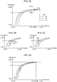
- the cell 9a (represented by the thick solid line) has the highest voltage when the external charging is completed and thereby the battery 13 is fully charged while the cell 9c (represented by the chain line) has the lowest voltage under the fully-charged state. Namely, the cell 9c corresponds to the lowest cell.
- the cells 9b and 9c have the same capacity when having the intersection voltage V Z , and the cell 9c has a higher voltage than that of the cell 9b at a region in which the voltage is lower than the intersection voltage V Z .
- the voltage difference ⁇ V X between the lowest voltage V XMIN and the highest voltage V XMAX is calculated, and then the allowable time T MAX of carrying out the balancer control is set on the basis of the capacity difference ⁇ C, which corresponds to the voltage difference ⁇ V X .
- the calculator 2 calculates the voltage difference ⁇ V Y between the highest voltage V YMAX and the target voltage V TGT as depicted in FIG. 5B .
- the voltage difference ⁇ V Y corresponds to the distance along the axis of ordinate between the thick solid line and the chain line.
- the electric power stored in the battery 13 is appropriately supplemented by typical electric power generation and regeneration, so that the voltages of the respective cells 9 are maintained to be certain values or higher.
- the balancer control is started. The balancer control will be carried out on only the cell 9a, which currently has a voltage higher than the target voltage V TGT , and will not be carried out on the cell 9b.
- the balancer control turns on the switch 18 of the balancer circuit 8 of the cell 9a, and thereby let electricity flow the corresponding resistor 17.
- the resistor 17 consumes the electric power stored in the cell 9a, so that the voltage of the cell 9a gradually falls as expressed by the arrow in FIG. 5C .
- the dispersion of voltages of the respective cell 9 corresponds to the dispersion of plots along the axis of ordinate of the graph. Therefore, the state of FIG. 5C has a smaller dispersion of voltages than that of FIG. 5B .
- it is difficult to illustrate, on the graph of FIG. 5C the dispersion of voltages that would remain when the battery 13 in this state is going to be fully charged through external charging.
- FIG. 5D has graphs obtained by moving the thick solid line of FIG. 5C rightward such that the abscissas of the while dots of FIG. 5C , which represents the states of the respective cells 9a, 9b, 9c, coincide with one another.
- the thin solid line in FIG. 5D corresponds to the thick solid line in FIG. 5C ; the thick solid line in FIG. 5D corresponds to a result of horizontally (i.e., along the axis of abscissa) moving the thin solid line by the distance S.
- the longest distance along the axis of ordinate between two of the white dots that is, the white dot representing the current highest cell voltage and the white dot representing the current lowest cell voltage---correspond to the extent of the dispersion of voltages remaining in the battery 13 at the time.
- the highest voltage among the voltages of all the cells 9 becomes to the upper limit voltage V HI .
- the leftmost intersection point corresponds to the highest voltage when the battery 13 is fully charged.
- the voltages of the remaining cells 9 when the battery 13 is fully charged are represented by the points having the same abscissa as that of the highest voltage.
- the extent of the dispersion of voltages of the cells 9 when the battery 13 is fully charged changes according to the distance S to move the thick solid line. Specifically, as depicted in FIG. 5C , the extent of the dispersion of voltages changes according to the amount of variation in battery capacity, which corresponds to the amount of variation in voltage of the cell 9a before and after the balancer control.
- FIG. 6A is an enlargement of a portion close to the full-charging point of FIG. 5D .
- the graph of the charging-discharging characteristics of the cell 9a is represented by the solid line A in FIG. 6A ---in other words, when the cell 9a has the upper limit voltage V HI under a state where the battery 13 is fully charged---the extent of the dispersion of voltages depends on the voltage of the cell 9a and the voltage of the cell 9c. As long as the cell 9a has the upper limit voltage V HI , a longer distance S to move the thick solid line increases the capacity of the cell 9a when the battery 13 is fully charged, so that the dispersion of voltages of the battery 13 reduces.
- the graph of the charging-discharging characteristics of the cell 9a is represented by the solid line B in FIG. 6A ---in other words, when the cell 9b has the upper limit voltage V HI under a state where the battery 13 is fully charged---the extent of the dispersion of voltages depends on the voltage of the cell 9b and the voltage of the cell 9c.
- the voltage of the cell 9a is a value between the voltages of the cells 9b and 9c.
- FIG. 6B is a graph denoting the relationship between the cumulative time T of carrying out the balancer control and the extent of dispersion of voltages, which relationship correlates with the above distance S.
- the cumulative time T of carrying out the balancer control reaches a certain extent, the dispersion of voltages reduces in accordance with increase in cumulative time T.
- the dispersion of voltages is constant. As long as an inequality "T 1 ⁇ T ⁇ T 2 " is true, the dispersion of voltages is constant.
- the calculator 2 in the BMU 7 calculates the voltage difference ⁇ V X when the battery 13 is fully charged.
- the voltage difference ⁇ V X is calculated by subtracting the lowest voltage V XMIN from the highest voltage V XMAX . Both values of these voltages ⁇ V XMAX , V XMIN are detected values when the battery 13 is fully charged.
- the calculator 2 in the BMU 7 also calculates the capacity difference ⁇ C corresponding to the voltage difference ⁇ V X . And then, the setter 3 sets the allowable time T MAX of balancer control, which corresponds to the quotient of the division of the capacity difference ⁇ C by the operational electric current I of the balancer circuit 8.
- the cell-balancer 5 starts balancer control.
- the balancer circuit 8 reduces the voltage of the cell 9a to the substantially same as the voltage of the cell 9c under a state where the battery 13 is fully charged (i.e., in the range in which the allowable time T MAX at least satisfies the relationship T MAX ⁇ T 2 )
- the balancer control is prohibited from being performed any longer.
- the distance S to move the thick solid line in FIG. 6A is limited such that the thick solid line is prohibited from coming below the point Q. Accordingly, the dispersion of voltages when the battery 13 is fully charged is the substantially minimum value associated with the charging-discharging characteristics of the respective cells 9.
- FIGs. 7A-7D are graphs denoting the sequence of activating the balancer circuits 8 when the balancer control is to be carried out on M cells (where, M is a natural number).
- M is a natural number.
- cell numbers #1, #2, #3, ..., and #M are applied to cells 9 in the order of having higher voltages at the time of starting the balancer control, and a voltage of the cell having the cell number #M when the balancer control is to be carried out corresponds to the target voltage V TGT .
- the balancer circuit 8 of the cell having the cell number #1 which cell has the highest voltage among the cells having voltages higher than the target voltage V TGT , is the first to be activated.
- the cell-balancer 5 activates only the balancer circuit 8 of the cell 9 having the cell number #1 towards the target voltage V TGT of the cell 9 having the cell number #M.
- This control corresponds to horizontally translating only the graph represented by the thick solid line of FIG. 7A along the axis of abscissa.
- the voltage of the cell 9 having the cell number #1 coincides with that of the cell 9 having the cell number #2, so that these two cells 9 have the current highest voltage.
- the cell-balancer 5 activates the balancer circuits 8 of the cells 9 having the cell numbers #1 and #2 towards the target voltage V TGT of the cell 9 having the cell number #M.
- This control corresponds to horizontally translating the graphs represented by the thick solid line and the middle solid line of FIG. 7B along the abscissa.
- the respective balancer circuits 8 are to be activated in the order of higher voltages that the corresponding cells 9 have.
- the number of the working balancer circuit 8 increases as the cumulative time T of carrying out the balancer control increases.
- the balancer control horizontally translates graphs in the order from the cell of the least deteriorating (represented by the leftmost graph)---that is, in the order of cells less deteriorating---such that the number of the graphs to be translated increase as time elapses.
- the cumulative time T reaches the allowable time T MAX
- the voltages of all the cells 9 having the cell numbers #1-#M come to be the substantially same as the target voltage V TGT , so that the balancer control is completed.
- FIGs. 8A-8C are graphs representing the results of simulating the extent of the dispersion of voltages of the cells when the battery 13 is fully charged, assuming that the cell 9a is a new that does not deteriorate and the degrees of deterioration of the cells 9b and 9c are large and small, respectively.
- FIG. 8A is a graph of the charging-discharging characteristics of the cells 9a-9c.
- the extent of the dispersion of voltages when the battery 13 is fully charged corresponds to the distance along the axis of the ordinate between two black dots in FIG. 8A .
- FIGs. 8B and 8C are graphs that forecast the change in the dispersion of voltages as a result of carrying balancer control performed when the voltages of the cells 9a-9c are in the states of the respective white dots of FIG. 8A while the battery 13 are being used.
- the balancer control is carried out such that the voltages of the cells 9a and 9c coincide with the voltage of the cell 9b.
- the voltage difference ⁇ V X between the solid line and the chain line which are horizontally translated so as to be drawn through the point P1 under a circumstance where the battery 13 is fully charged, corresponds to the extent of dispersion of voltages.
- FIG. 8B depicts that the voltage difference ⁇ V X increases from the initial voltage difference ⁇ V X of FIG. 8A in this instance.
- the balancer control is carried out such that the voltage of the cell 9a coincides with that of the cell 9c. Consequently, the cell 9b is excluded from the balance control.
- the voltage difference ⁇ V X when the solid line is horizontally translated so as to pass through the point P2 under a circumstance where the battery 13 is fully charged, corresponds to the extent of dispersion of voltages.
- FIG. 8C depicts that the voltage difference ⁇ V X decreases from the initial voltage difference ⁇ V X of FIG. 8A , which means the balancer control of FIG 8C suppresses the dispersion of voltages.
- each balancer circuit 8 is assumed to be a resistor bypass circuit, but is not limited to this.
- the balancer circuit 8 may have a configuration to control the voltages of the multiple cells 9 in a lump instead of the configuration to control the voltage of each individual cell 9, or may distribute electric power among the multiple cells 9.
- one scheme is to control the average voltage of the respective battery modules.
- a battery module including a cell which has the lowest voltage when the multiple battery modules are fully charged is treated the same as the lowest cell of the first embodiment and the remaining battery modules are treated the same as the remaining cells of the first embodiment, so that the same effects and advantages as the first embodiment can be attained.
- the above first embodiment assumes the balancer control to be carried out on an assembled battery of a lithium-ion secondary battery.
- the kind of battery is not limited to this.
- the balancer control may be carried out on a lead-acid battery (a so-called 12-V battery) mounted on the vehicle 10, or on an assembled battery including lithium-ion capacitors, Nickel-Metal Hydride batteries, or alkaline-ion battery instead of a lithium-ion secondary battery.
- Condition 3 of the first embodiment compares the largeness of the voltage difference ⁇ V Y and the criterional voltage difference ⁇ V TH . Specifically, determiner 4 determines how high the highest voltage V YMAX is relative to the target voltage V TGT . Determination of Condition 3 may be substituted by calculating the voltage difference ⁇ V Z between the voltage of each individual cell 9 and the target voltage ⁇ V TGT and then comparing the largeness of the voltage difference ⁇ V Z with that of the criterional voltage difference ⁇ V TH . Specifically, determination as to whether the balancer control is to be carried out is made on each individual cell.
- the balancer control is assumed to be carried out on a vehicle running (including stopping and halting, i.e., difference ⁇ VTH. Specifically, determination as to whether the balancer control is to be carried out is made on each individual cell.
- the balancer control is assumed to be carried out on a vehicle running (including stopping and halting, i.e., when not being subjected to external charging).
- the balancer control can be carried out also during external charging.
- the balancer control is carried out in a voltage region lower than the intersection voltage VZ. This makes it possible to further reduce the dispersion of voltages when the battery 13 is fully charged as compared with conventional cell-balancing and also to suppress increase in dispersion of voltages caused by the change in chargeable amount related to deterioration of charging-discharging characteristics of the respective cells.
Landscapes
- Engineering & Computer Science (AREA)
- Power Engineering (AREA)
- Transportation (AREA)
- Mechanical Engineering (AREA)
- Life Sciences & Earth Sciences (AREA)
- Sustainable Development (AREA)
- Sustainable Energy (AREA)
- Secondary Cells (AREA)
- Charge And Discharge Circuits For Batteries Or The Like (AREA)
- Electric Propulsion And Braking For Vehicles (AREA)
- Battery Mounting, Suspending (AREA)
- Hybrid Electric Vehicles (AREA)
Claims (3)
- Batteriemanagementeinheit für ein Fahrzeug, die Folgendes umfasst:ein Ladegerät (14), das so konfiguriert ist, dass es im Fahrzeug (10) montiert wird, um eine zusammengebaute Batterie (13) mit einer Mehrzahl von Zellen (9) mit elektrischer Leistung von einer externen Leistungsquelle aufzuladen;einen Speicher (1) zum Aufzeichnen, welche Zelle eine unterste Zelle mit der niedrigsten Spannung ist, wenn die zusammengebaute Batterie (13) unter der Mehrzahl von Zellen (9) vollständig geladen wird;einen Zellausgleicher (5) zur Durchführung des Zellausgleichs an der Spannung der zusammengebauten Batterie (13) durch Entladen, wenn das Ladegerät (14) die zusammengebaute Batterie (13), eine oder mehr Zellen (9), nicht auflädt, die jeweils gerade eine Spannung haben, die höher als eine aktuelle Spannung der untersten Zelle (9) im Vergleich zur aktuellen Spannung der untersten Zelle (9) ist;gekennzeichnet durch einen Rechner (2), der so konfiguriert ist, dass er eine Zellkapazitätsdifferenz (ΔC) basierend auf der Differenz zwischen einer untersten Spannung und einer höchsten Spannung unter den Spannungen der Mehrzahl von Zellen (9) berechnet, wenn die zusammengebaute Batterie (13) vollständig geladen ist; undeine Einstelleinrichtung (3), die so konfiguriert ist, dass sie eine Obergrenze (TMAX) von kumulativer Zeit für die Durchführung des Zellausgleichs basierend auf einem Stromverbrauch (I) des Zellausgleichs und der Zellkapazitätsdifferenz (ΔC) setzt, die vom Rechner (2) berechnet wird, wobei der Ausgleich durchgeführt wird, wenn ein Absolutwert eines elektrischen Stroms, der die zusammengebaute Batterie (13) auflädt oder entlädt, geringer als ein als Kriterium bekannter elektrischer Stromwert ist und die Spannungsdifferenz (ΔVY) zwischen einer maximalen Spannung (VYMAX) der Zellen (9) und einer Zielspannung (VTGT) eine als Kriterium bekannte Spannungsdifferenz (ΔVTH) übersteigt.
- Batteriemanagementeinheit nach Anspruch 1, worin der Zell ausgleicher (5) verhindert, dass der Zellausgleich für eine kumulative Zeit durchgeführt wird, die länger als die Obergrenze (TMAX) ist, die von der Einstelleinrichtung (3) gesetzt wird.
- Batteriemanagementeinheit nach Anspruch 2, worin die Einstelleinrichtung (3) die Obergrenze (TMAX) zurücksetzt, wenn die zusammengebaute Batterie (13) vollständig aufgeladen ist.
Applications Claiming Priority (1)
| Application Number | Priority Date | Filing Date | Title |
|---|---|---|---|
| JP2012154665A JP5987512B2 (ja) | 2012-07-10 | 2012-07-10 | 車両の電池制御装置 |
Publications (2)
| Publication Number | Publication Date |
|---|---|
| EP2685591A1 EP2685591A1 (de) | 2014-01-15 |
| EP2685591B1 true EP2685591B1 (de) | 2017-11-08 |
Family
ID=48782222
Family Applications (1)
| Application Number | Title | Priority Date | Filing Date |
|---|---|---|---|
| EP13175428.5A Active EP2685591B1 (de) | 2012-07-10 | 2013-07-05 | Batterieverwaltungseinheit für ein Fahrzeug |
Country Status (4)
| Country | Link |
|---|---|
| US (1) | US9278622B2 (de) |
| EP (1) | EP2685591B1 (de) |
| JP (1) | JP5987512B2 (de) |
| CN (1) | CN103545862B (de) |
Cited By (2)
| Publication number | Priority date | Publication date | Assignee | Title |
|---|---|---|---|---|
| EP4521591A1 (de) * | 2023-09-08 | 2025-03-12 | Samsung SDI Co., Ltd. | Vorrichtung und verfahren zur batterieausgleichssteuerung |
| US12614913B2 (en) | 2023-09-08 | 2026-04-28 | Samsung Sdi Co., Ltd. | Apparatus and method for controlling balance of battery |
Families Citing this family (21)
| Publication number | Priority date | Publication date | Assignee | Title |
|---|---|---|---|---|
| WO2012122250A1 (en) | 2011-03-07 | 2012-09-13 | A123 Systems, Inc. | Method for opportunistically balancing charge between battery cells |
| KR101741303B1 (ko) * | 2014-10-27 | 2017-05-29 | 주식회사 엘지화학 | 배터리 랙 간 전압 밸런싱 장치 및 방법 |
| KR101601713B1 (ko) | 2014-11-17 | 2016-03-09 | 현대오트론 주식회사 | 배터리 셀 밸런싱 장치 및 방법 |
| KR101601714B1 (ko) | 2014-11-19 | 2016-03-09 | 현대오트론 주식회사 | 배터리 셀 밸런싱 장치 및 방법 |
| JP6468479B2 (ja) * | 2014-12-17 | 2019-02-13 | 株式会社Ihi | 電池システム、制御装置及び電池制御方法 |
| US10181733B2 (en) | 2015-12-23 | 2019-01-15 | Lg Chem, Ltd. | Apparatus and method of balancing voltages between battery racks |
| CN105553009B (zh) * | 2015-12-26 | 2017-03-22 | 惠州市蓝微新源技术有限公司 | 开关阵列快速均衡电池组的均衡电路及控制方法 |
| JP6573120B2 (ja) | 2016-01-26 | 2019-09-11 | 株式会社Gsユアサ | 状態推定装置、蓄電素子モジュール、車両、及び状態推定方法 |
| JP2018117438A (ja) * | 2017-01-17 | 2018-07-26 | 太陽誘電株式会社 | リチウムイオンキャパシタを備えた電源モジュール |
| US10391864B2 (en) | 2017-02-08 | 2019-08-27 | Toyota Motor Engineering & Manufacturing North America, Inc. | System to balance high voltage battery for vehicle |
| KR102008518B1 (ko) * | 2017-05-30 | 2019-08-07 | 주식회사 이랜텍 | 멀티 셀 충전 시스템 |
| US11173807B2 (en) * | 2017-06-09 | 2021-11-16 | Ford Global Technologies, Llc | Battery charge equalization system timer |
| DE102018201031A1 (de) | 2018-01-24 | 2019-07-25 | Robert Bosch Gmbh | Verfahren zum Betrieb eines Batteriesystems |
| WO2019147244A1 (en) * | 2018-01-25 | 2019-08-01 | Volvo Construction Equipment Ab | Equalizer overload management |
| KR102802132B1 (ko) * | 2019-02-20 | 2025-04-28 | 삼성에스디아이 주식회사 | 배터리 제어 장치 및 배터리 제어 방법 |
| CN109756001B (zh) * | 2019-03-13 | 2022-03-11 | 北汽福田汽车股份有限公司 | 电动汽车、电池系统及其均衡方法和装置 |
| JP7613021B2 (ja) * | 2020-07-30 | 2025-01-15 | 株式会社Gsユアサ | 蓄電量調整方法、蓄電装置及びコンピュータプログラム |
| US11689043B2 (en) | 2021-10-31 | 2023-06-27 | Beta Air, Llc | Systems and methods for regulating charging of an electric aircraft |
| CN116409202A (zh) * | 2021-12-30 | 2023-07-11 | 中兴通讯股份有限公司 | 电池组控制方法、系统及计算机可读存储介质 |
| CN114859253B (zh) * | 2022-05-18 | 2025-11-14 | 智租物联科技集团有限公司 | 一种基于物联网技术的电池剩余容量计算预估方法 |
| CN119134612B (zh) * | 2024-11-15 | 2025-03-28 | 杭州煦达新能源科技有限公司 | 基于电芯工作状态的电池系统均衡方法及装置 |
Family Cites Families (26)
| Publication number | Priority date | Publication date | Assignee | Title |
|---|---|---|---|---|
| US6225780B1 (en) * | 2000-02-24 | 2001-05-01 | General Motors Corporation | Battery charge maintenance through opportunity equalization |
| JP3882663B2 (ja) | 2002-04-12 | 2007-02-21 | 日産自動車株式会社 | 充放電制御装置 |
| JP3539424B2 (ja) * | 2002-07-24 | 2004-07-07 | 日産自動車株式会社 | 電気自動車の制御装置 |
| JP2006166615A (ja) * | 2004-12-08 | 2006-06-22 | Fuji Heavy Ind Ltd | 蓄電デバイスの電圧均等化制御システム |
| JP4560501B2 (ja) * | 2006-08-11 | 2010-10-13 | 矢崎総業株式会社 | 充電状態調整装置 |
| US20080084182A1 (en) * | 2006-10-06 | 2008-04-10 | Aai Corporation | Lithium battery system |
| US8288991B2 (en) * | 2007-04-18 | 2012-10-16 | Valeo Equipements Electriques Moteur | Energy storage device with assembly of energy storage cells and balancing circuit |
| US8273483B2 (en) * | 2008-02-14 | 2012-09-25 | The Gillette Company | Lithium cell |
| US8482256B2 (en) * | 2008-09-11 | 2013-07-09 | Ecosol Technologies Inc. | Portable charging power system for battery-powered devices |
| US8350528B2 (en) * | 2009-02-04 | 2013-01-08 | Samsung Sdi Co., Ltd. | Battery pack and balancing method of battery cells |
| CN102308431A (zh) * | 2009-02-09 | 2012-01-04 | 伊克斯动力有限公司 | 对电池进行放电 |
| JP5493407B2 (ja) * | 2009-03-17 | 2014-05-14 | 日産自動車株式会社 | 組電池の容量調整装置 |
| DE102009032050A1 (de) * | 2009-07-07 | 2011-01-27 | Li-Tec Battery Gmbh | Sekundärbatterie mit Schnellladefähigkeit |
| JP5381664B2 (ja) * | 2009-12-02 | 2014-01-08 | トヨタ自動車株式会社 | 組電池の異常検出装置 |
| JP5736694B2 (ja) * | 2010-09-03 | 2015-06-17 | ソニー株式会社 | 制御装置及び方法、並びに電源装置 |
| CN102652265A (zh) * | 2010-12-06 | 2012-08-29 | 科达汽车公司 | 使用电路故障自检测量装置来测量隔离高压以及检测隔离击穿 |
| US8598847B2 (en) * | 2010-12-07 | 2013-12-03 | Volkswagen Ag | Balancing voltage for a multi-cell battery system |
| JP2012135154A (ja) * | 2010-12-22 | 2012-07-12 | Denso Corp | リチウムイオン二次電池の充電制御装置 |
| KR101256079B1 (ko) * | 2010-12-28 | 2013-04-19 | 삼성에스디아이 주식회사 | 배터리 팩의 밸런싱 방법 및 밸런싱 시스템 |
| CN102457078A (zh) * | 2011-03-30 | 2012-05-16 | 凹凸电子(武汉)有限公司 | 电池均衡电路、电池均衡系统及方法 |
| TWI423557B (zh) * | 2011-05-11 | 2014-01-11 | 廣達電腦股份有限公司 | 使用可充電電池之電子產品與其電池狀態控制方法 |
| JP5304844B2 (ja) * | 2011-05-24 | 2013-10-02 | トヨタ自動車株式会社 | バッテリの充電制御装置 |
| US8710800B2 (en) * | 2011-07-26 | 2014-04-29 | GM Global Technology Operations LLC | Vehicle battery with cell balancing current paths and method of charging the same |
| US8676419B2 (en) * | 2011-07-28 | 2014-03-18 | Ford Global Technologies, Llc | Time-based vehicle battery balancing system and method |
| US9139103B2 (en) * | 2011-07-28 | 2015-09-22 | Ford Global Technologies, Llc | Battery cell capacity balancing system and method |
| CN102522798B (zh) * | 2011-12-30 | 2014-01-08 | 深圳桑达国际电子器件有限公司 | 一种电池组模块之间的主动均衡电路 |
-
2012
- 2012-07-10 JP JP2012154665A patent/JP5987512B2/ja active Active
-
2013
- 2013-07-05 EP EP13175428.5A patent/EP2685591B1/de active Active
- 2013-07-09 CN CN201310287443.9A patent/CN103545862B/zh active Active
- 2013-07-09 US US13/937,316 patent/US9278622B2/en active Active
Non-Patent Citations (1)
| Title |
|---|
| None * |
Cited By (2)
| Publication number | Priority date | Publication date | Assignee | Title |
|---|---|---|---|---|
| EP4521591A1 (de) * | 2023-09-08 | 2025-03-12 | Samsung SDI Co., Ltd. | Vorrichtung und verfahren zur batterieausgleichssteuerung |
| US12614913B2 (en) | 2023-09-08 | 2026-04-28 | Samsung Sdi Co., Ltd. | Apparatus and method for controlling balance of battery |
Also Published As
| Publication number | Publication date |
|---|---|
| JP2014017997A (ja) | 2014-01-30 |
| US20140015483A1 (en) | 2014-01-16 |
| EP2685591A1 (de) | 2014-01-15 |
| JP5987512B2 (ja) | 2016-09-07 |
| CN103545862A (zh) | 2014-01-29 |
| US9278622B2 (en) | 2016-03-08 |
| CN103545862B (zh) | 2016-08-10 |
Similar Documents
| Publication | Publication Date | Title |
|---|---|---|
| EP2685591B1 (de) | Batterieverwaltungseinheit für ein Fahrzeug | |
| CN102445665B (zh) | 蓄电池组容量学习算法 | |
| CN108292854B (zh) | 电池控制装置 | |
| US7245107B2 (en) | System and method for battery charge control based on a cycle life parameter | |
| US10283974B2 (en) | Systems and methods for intelligent, adaptive management of energy storage packs | |
| KR20190000445A (ko) | 전기자동차용 배터리의 열화 발생을 저감하면서 고속충전과 최대방전을 수행하기 위한 방법 및 그 장치 | |
| US20120161709A1 (en) | Secondary-battery control apparatus | |
| KR20070074544A (ko) | 리치움밧데리 시스템에 대한 셀 바란싱 방법 | |
| KR102274812B1 (ko) | 병렬 연결된 배터리 셀들의 가용 용량 최적화를 위한 동적 저항 배터리 셀 균등화 장치 | |
| US20240094306A1 (en) | Apparatus and method for estimating battery cell capacity | |
| CN115173511A (zh) | 一种动力电池均衡方法及装置 | |
| CN117378116A (zh) | 用于控制输出电压的电路装置 | |
| CN118944244A (zh) | 电池均衡控制方法 | |
| KR101558705B1 (ko) | 배터리 충전 제어 장치 및 방법 | |
| JP6711221B2 (ja) | 電池システム | |
| KR101925113B1 (ko) | 복수의 배터리 유닛들을 포함하는 전지팩의 충전량을 향상시키기 위한 전지팩 충전기 | |
| JP2017060313A (ja) | 車両の電源システム | |
| JP2001177918A (ja) | 自己発電型電気自動車用電池の制御方法 | |
| JP7701098B2 (ja) | バッテリー制御装置及び方法 | |
| JP6897479B2 (ja) | 二次電池システム | |
| US20150229142A1 (en) | Battery control device, electric storage device, method for operating electric storage device, and program | |
| JP7587747B2 (ja) | 蓄電装置、その充電方法、および、その充電制御プログラム | |
| WO2022209546A1 (ja) | 均等化装置 | |
| CN115395118A (zh) | 电池包充电平衡控制方法、装置、电池管理系统及介质 | |
| Dehghani et al. | Decentralized Battery Charger with High Precision Active Equalization Capability |
Legal Events
| Date | Code | Title | Description |
|---|---|---|---|
| PUAI | Public reference made under article 153(3) epc to a published international application that has entered the european phase |
Free format text: ORIGINAL CODE: 0009012 |
|
| AK | Designated contracting states |
Kind code of ref document: A1 Designated state(s): AL AT BE BG CH CY CZ DE DK EE ES FI FR GB GR HR HU IE IS IT LI LT LU LV MC MK MT NL NO PL PT RO RS SE SI SK SM TR |
|
| AX | Request for extension of the european patent |
Extension state: BA ME |
|
| 17P | Request for examination filed |
Effective date: 20140702 |
|
| RBV | Designated contracting states (corrected) |
Designated state(s): AL AT BE BG CH CY CZ DE DK EE ES FI FR GB GR HR HU IE IS IT LI LT LU LV MC MK MT NL NO PL PT RO RS SE SI SK SM TR |
|
| GRAP | Despatch of communication of intention to grant a patent |
Free format text: ORIGINAL CODE: EPIDOSNIGR1 |
|
| INTG | Intention to grant announced |
Effective date: 20170607 |
|
| RAP1 | Party data changed (applicant data changed or rights of an application transferred) |
Owner name: MITSUBISHI JIDOSHA KOGYO KABUSHIKI KAISHA |
|
| GRAS | Grant fee paid |
Free format text: ORIGINAL CODE: EPIDOSNIGR3 |
|
| GRAA | (expected) grant |
Free format text: ORIGINAL CODE: 0009210 |
|
| AK | Designated contracting states |
Kind code of ref document: B1 Designated state(s): AL AT BE BG CH CY CZ DE DK EE ES FI FR GB GR HR HU IE IS IT LI LT LU LV MC MK MT NL NO PL PT RO RS SE SI SK SM TR |
|
| REG | Reference to a national code |
Ref country code: GB Ref legal event code: FG4D |
|
| REG | Reference to a national code |
Ref country code: CH Ref legal event code: EP Ref country code: AT Ref legal event code: REF Ref document number: 945041 Country of ref document: AT Kind code of ref document: T Effective date: 20171115 |
|
| REG | Reference to a national code |
Ref country code: IE Ref legal event code: FG4D |
|
| REG | Reference to a national code |
Ref country code: DE Ref legal event code: R096 Ref document number: 602013029008 Country of ref document: DE |
|
| REG | Reference to a national code |
Ref country code: NL Ref legal event code: MP Effective date: 20171108 |
|
| REG | Reference to a national code |
Ref country code: LT Ref legal event code: MG4D |
|
| REG | Reference to a national code |
Ref country code: AT Ref legal event code: MK05 Ref document number: 945041 Country of ref document: AT Kind code of ref document: T Effective date: 20171108 |
|
| PG25 | Lapsed in a contracting state [announced via postgrant information from national office to epo] |
Ref country code: FI Free format text: LAPSE BECAUSE OF FAILURE TO SUBMIT A TRANSLATION OF THE DESCRIPTION OR TO PAY THE FEE WITHIN THE PRESCRIBED TIME-LIMIT Effective date: 20171108 Ref country code: ES Free format text: LAPSE BECAUSE OF FAILURE TO SUBMIT A TRANSLATION OF THE DESCRIPTION OR TO PAY THE FEE WITHIN THE PRESCRIBED TIME-LIMIT Effective date: 20171108 Ref country code: LT Free format text: LAPSE BECAUSE OF FAILURE TO SUBMIT A TRANSLATION OF THE DESCRIPTION OR TO PAY THE FEE WITHIN THE PRESCRIBED TIME-LIMIT Effective date: 20171108 Ref country code: NO Free format text: LAPSE BECAUSE OF FAILURE TO SUBMIT A TRANSLATION OF THE DESCRIPTION OR TO PAY THE FEE WITHIN THE PRESCRIBED TIME-LIMIT Effective date: 20180208 Ref country code: NL Free format text: LAPSE BECAUSE OF FAILURE TO SUBMIT A TRANSLATION OF THE DESCRIPTION OR TO PAY THE FEE WITHIN THE PRESCRIBED TIME-LIMIT Effective date: 20171108 Ref country code: SE Free format text: LAPSE BECAUSE OF FAILURE TO SUBMIT A TRANSLATION OF THE DESCRIPTION OR TO PAY THE FEE WITHIN THE PRESCRIBED TIME-LIMIT Effective date: 20171108 |
|
| PG25 | Lapsed in a contracting state [announced via postgrant information from national office to epo] |
Ref country code: LV Free format text: LAPSE BECAUSE OF FAILURE TO SUBMIT A TRANSLATION OF THE DESCRIPTION OR TO PAY THE FEE WITHIN THE PRESCRIBED TIME-LIMIT Effective date: 20171108 Ref country code: IS Free format text: LAPSE BECAUSE OF FAILURE TO SUBMIT A TRANSLATION OF THE DESCRIPTION OR TO PAY THE FEE WITHIN THE PRESCRIBED TIME-LIMIT Effective date: 20180308 Ref country code: BG Free format text: LAPSE BECAUSE OF FAILURE TO SUBMIT A TRANSLATION OF THE DESCRIPTION OR TO PAY THE FEE WITHIN THE PRESCRIBED TIME-LIMIT Effective date: 20180208 Ref country code: HR Free format text: LAPSE BECAUSE OF FAILURE TO SUBMIT A TRANSLATION OF THE DESCRIPTION OR TO PAY THE FEE WITHIN THE PRESCRIBED TIME-LIMIT Effective date: 20171108 Ref country code: GR Free format text: LAPSE BECAUSE OF FAILURE TO SUBMIT A TRANSLATION OF THE DESCRIPTION OR TO PAY THE FEE WITHIN THE PRESCRIBED TIME-LIMIT Effective date: 20180209 Ref country code: AT Free format text: LAPSE BECAUSE OF FAILURE TO SUBMIT A TRANSLATION OF THE DESCRIPTION OR TO PAY THE FEE WITHIN THE PRESCRIBED TIME-LIMIT Effective date: 20171108 Ref country code: RS Free format text: LAPSE BECAUSE OF FAILURE TO SUBMIT A TRANSLATION OF THE DESCRIPTION OR TO PAY THE FEE WITHIN THE PRESCRIBED TIME-LIMIT Effective date: 20171108 |
|
| PG25 | Lapsed in a contracting state [announced via postgrant information from national office to epo] |
Ref country code: DK Free format text: LAPSE BECAUSE OF FAILURE TO SUBMIT A TRANSLATION OF THE DESCRIPTION OR TO PAY THE FEE WITHIN THE PRESCRIBED TIME-LIMIT Effective date: 20171108 Ref country code: CY Free format text: LAPSE BECAUSE OF FAILURE TO SUBMIT A TRANSLATION OF THE DESCRIPTION OR TO PAY THE FEE WITHIN THE PRESCRIBED TIME-LIMIT Effective date: 20171108 Ref country code: CZ Free format text: LAPSE BECAUSE OF FAILURE TO SUBMIT A TRANSLATION OF THE DESCRIPTION OR TO PAY THE FEE WITHIN THE PRESCRIBED TIME-LIMIT Effective date: 20171108 Ref country code: EE Free format text: LAPSE BECAUSE OF FAILURE TO SUBMIT A TRANSLATION OF THE DESCRIPTION OR TO PAY THE FEE WITHIN THE PRESCRIBED TIME-LIMIT Effective date: 20171108 Ref country code: SK Free format text: LAPSE BECAUSE OF FAILURE TO SUBMIT A TRANSLATION OF THE DESCRIPTION OR TO PAY THE FEE WITHIN THE PRESCRIBED TIME-LIMIT Effective date: 20171108 |
|
| REG | Reference to a national code |
Ref country code: DE Ref legal event code: R097 Ref document number: 602013029008 Country of ref document: DE |
|
| PG25 | Lapsed in a contracting state [announced via postgrant information from national office to epo] |
Ref country code: RO Free format text: LAPSE BECAUSE OF FAILURE TO SUBMIT A TRANSLATION OF THE DESCRIPTION OR TO PAY THE FEE WITHIN THE PRESCRIBED TIME-LIMIT Effective date: 20171108 Ref country code: IT Free format text: LAPSE BECAUSE OF FAILURE TO SUBMIT A TRANSLATION OF THE DESCRIPTION OR TO PAY THE FEE WITHIN THE PRESCRIBED TIME-LIMIT Effective date: 20171108 Ref country code: SM Free format text: LAPSE BECAUSE OF FAILURE TO SUBMIT A TRANSLATION OF THE DESCRIPTION OR TO PAY THE FEE WITHIN THE PRESCRIBED TIME-LIMIT Effective date: 20171108 Ref country code: PL Free format text: LAPSE BECAUSE OF FAILURE TO SUBMIT A TRANSLATION OF THE DESCRIPTION OR TO PAY THE FEE WITHIN THE PRESCRIBED TIME-LIMIT Effective date: 20171108 |
|
| PLBE | No opposition filed within time limit |
Free format text: ORIGINAL CODE: 0009261 |
|
| STAA | Information on the status of an ep patent application or granted ep patent |
Free format text: STATUS: NO OPPOSITION FILED WITHIN TIME LIMIT |
|
| 26N | No opposition filed |
Effective date: 20180809 |
|
| PG25 | Lapsed in a contracting state [announced via postgrant information from national office to epo] |
Ref country code: SI Free format text: LAPSE BECAUSE OF FAILURE TO SUBMIT A TRANSLATION OF THE DESCRIPTION OR TO PAY THE FEE WITHIN THE PRESCRIBED TIME-LIMIT Effective date: 20171108 |
|
| REG | Reference to a national code |
Ref country code: CH Ref legal event code: PL |
|
| GBPC | Gb: european patent ceased through non-payment of renewal fee |
Effective date: 20180705 |
|
| PG25 | Lapsed in a contracting state [announced via postgrant information from national office to epo] |
Ref country code: LU Free format text: LAPSE BECAUSE OF NON-PAYMENT OF DUE FEES Effective date: 20180705 Ref country code: MC Free format text: LAPSE BECAUSE OF FAILURE TO SUBMIT A TRANSLATION OF THE DESCRIPTION OR TO PAY THE FEE WITHIN THE PRESCRIBED TIME-LIMIT Effective date: 20171108 |
|
| REG | Reference to a national code |
Ref country code: BE Ref legal event code: MM Effective date: 20180731 |
|
| REG | Reference to a national code |
Ref country code: IE Ref legal event code: MM4A |
|
| PG25 | Lapsed in a contracting state [announced via postgrant information from national office to epo] |
Ref country code: LI Free format text: LAPSE BECAUSE OF NON-PAYMENT OF DUE FEES Effective date: 20180731 Ref country code: CH Free format text: LAPSE BECAUSE OF NON-PAYMENT OF DUE FEES Effective date: 20180731 Ref country code: IE Free format text: LAPSE BECAUSE OF NON-PAYMENT OF DUE FEES Effective date: 20180705 Ref country code: GB Free format text: LAPSE BECAUSE OF NON-PAYMENT OF DUE FEES Effective date: 20180705 |
|
| PG25 | Lapsed in a contracting state [announced via postgrant information from national office to epo] |
Ref country code: BE Free format text: LAPSE BECAUSE OF NON-PAYMENT OF DUE FEES Effective date: 20180731 |
|
| PG25 | Lapsed in a contracting state [announced via postgrant information from national office to epo] |
Ref country code: MT Free format text: LAPSE BECAUSE OF NON-PAYMENT OF DUE FEES Effective date: 20180705 |
|
| PG25 | Lapsed in a contracting state [announced via postgrant information from national office to epo] |
Ref country code: TR Free format text: LAPSE BECAUSE OF FAILURE TO SUBMIT A TRANSLATION OF THE DESCRIPTION OR TO PAY THE FEE WITHIN THE PRESCRIBED TIME-LIMIT Effective date: 20171108 |
|
| PG25 | Lapsed in a contracting state [announced via postgrant information from national office to epo] |
Ref country code: PT Free format text: LAPSE BECAUSE OF FAILURE TO SUBMIT A TRANSLATION OF THE DESCRIPTION OR TO PAY THE FEE WITHIN THE PRESCRIBED TIME-LIMIT Effective date: 20171108 Ref country code: HU Free format text: LAPSE BECAUSE OF FAILURE TO SUBMIT A TRANSLATION OF THE DESCRIPTION OR TO PAY THE FEE WITHIN THE PRESCRIBED TIME-LIMIT; INVALID AB INITIO Effective date: 20130705 |
|
| PG25 | Lapsed in a contracting state [announced via postgrant information from national office to epo] |
Ref country code: MK Free format text: LAPSE BECAUSE OF NON-PAYMENT OF DUE FEES Effective date: 20171108 |
|
| PG25 | Lapsed in a contracting state [announced via postgrant information from national office to epo] |
Ref country code: AL Free format text: LAPSE BECAUSE OF FAILURE TO SUBMIT A TRANSLATION OF THE DESCRIPTION OR TO PAY THE FEE WITHIN THE PRESCRIBED TIME-LIMIT Effective date: 20171108 |
|
| PGFP | Annual fee paid to national office [announced via postgrant information from national office to epo] |
Ref country code: FR Payment date: 20250610 Year of fee payment: 13 |
|
| PGFP | Annual fee paid to national office [announced via postgrant information from national office to epo] |
Ref country code: DE Payment date: 20250528 Year of fee payment: 13 |