EP2685454B1 - Determining head-to-disk contact and/or spacing using frequency domain signature of a temperature sensor - Google Patents
Determining head-to-disk contact and/or spacing using frequency domain signature of a temperature sensor Download PDFInfo
- Publication number
- EP2685454B1 EP2685454B1 EP13173883.3A EP13173883A EP2685454B1 EP 2685454 B1 EP2685454 B1 EP 2685454B1 EP 13173883 A EP13173883 A EP 13173883A EP 2685454 B1 EP2685454 B1 EP 2685454B1
- Authority
- EP
- European Patent Office
- Prior art keywords
- heater
- magnetic head
- temperature sensor
- spacing
- frequency
- Prior art date
- Legal status (The legal status is an assumption and is not a legal conclusion. Google has not performed a legal analysis and makes no representation as to the accuracy of the status listed.)
- Not-in-force
Links
- 230000008859 change Effects 0.000 claims description 28
- 238000000034 method Methods 0.000 claims description 16
- 230000004044 response Effects 0.000 claims description 14
- 238000010438 heat treatment Methods 0.000 description 9
- 238000005259 measurement Methods 0.000 description 8
- 238000001514 detection method Methods 0.000 description 7
- 230000007423 decrease Effects 0.000 description 4
- 238000013500 data storage Methods 0.000 description 3
- 230000009977 dual effect Effects 0.000 description 3
- 238000012546 transfer Methods 0.000 description 3
- 238000010586 diagram Methods 0.000 description 2
- 239000000463 material Substances 0.000 description 2
- 238000012545 processing Methods 0.000 description 2
- 230000035945 sensitivity Effects 0.000 description 2
- 230000003068 static effect Effects 0.000 description 2
- 230000003750 conditioning effect Effects 0.000 description 1
- 230000008878 coupling Effects 0.000 description 1
- 238000010168 coupling process Methods 0.000 description 1
- 238000005859 coupling reaction Methods 0.000 description 1
- 230000000694 effects Effects 0.000 description 1
- 238000012986 modification Methods 0.000 description 1
- 230000004048 modification Effects 0.000 description 1
- 230000010355 oscillation Effects 0.000 description 1
- 230000006903 response to temperature Effects 0.000 description 1
- 239000000725 suspension Substances 0.000 description 1
- 239000010409 thin film Substances 0.000 description 1
- 238000012876 topography Methods 0.000 description 1
Images


Classifications
-
- G—PHYSICS
- G11—INFORMATION STORAGE
- G11B—INFORMATION STORAGE BASED ON RELATIVE MOVEMENT BETWEEN RECORD CARRIER AND TRANSDUCER
- G11B21/00—Head arrangements not specific to the method of recording or reproducing
- G11B21/02—Driving or moving of heads
-
- G—PHYSICS
- G11—INFORMATION STORAGE
- G11B—INFORMATION STORAGE BASED ON RELATIVE MOVEMENT BETWEEN RECORD CARRIER AND TRANSDUCER
- G11B5/00—Recording by magnetisation or demagnetisation of a record carrier; Reproducing by magnetic means; Record carriers therefor
- G11B5/48—Disposition or mounting of heads or head supports relative to record carriers ; arrangements of heads, e.g. for scanning the record carrier to increase the relative speed
- G11B5/58—Disposition or mounting of heads or head supports relative to record carriers ; arrangements of heads, e.g. for scanning the record carrier to increase the relative speed with provision for moving the head for the purpose of maintaining alignment of the head relative to the record carrier during transducing operation, e.g. to compensate for surface irregularities of the latter or for track following
- G11B5/60—Fluid-dynamic spacing of heads from record-carriers
- G11B5/6005—Specially adapted for spacing from a rotating disc using a fluid cushion
- G11B5/6011—Control of flying height
- G11B5/607—Control of flying height using thermal means
-
- G—PHYSICS
- G11—INFORMATION STORAGE
- G11B—INFORMATION STORAGE BASED ON RELATIVE MOVEMENT BETWEEN RECORD CARRIER AND TRANSDUCER
- G11B5/00—Recording by magnetisation or demagnetisation of a record carrier; Reproducing by magnetic means; Record carriers therefor
- G11B5/48—Disposition or mounting of heads or head supports relative to record carriers ; arrangements of heads, e.g. for scanning the record carrier to increase the relative speed
- G11B5/58—Disposition or mounting of heads or head supports relative to record carriers ; arrangements of heads, e.g. for scanning the record carrier to increase the relative speed with provision for moving the head for the purpose of maintaining alignment of the head relative to the record carrier during transducing operation, e.g. to compensate for surface irregularities of the latter or for track following
- G11B5/60—Fluid-dynamic spacing of heads from record-carriers
- G11B5/6005—Specially adapted for spacing from a rotating disc using a fluid cushion
- G11B5/6011—Control of flying height
- G11B5/6076—Detecting head-disk contact
Definitions
- the present invention relates to a method for determining head-to-disk contact using a frequency domain signature of a temperature sensor.
- US Patent Application published as 2008/0239581 describes a disk drive for writing data to a magnetic medium.
- a constant alternating current is applied to a thin-film write coil.
- the frequency of the current is, e.g., > 10 kHz and preferably > 1 MHz.
- the coil voltage is detected and subjected to a Fourier transform. From the transform is extracted the amplitude of the frequency component corresponding to the frequency of the applied current. This eliminates the influence of noise on the detected voltage signal. Changes in this amplitude are monitored and, when a sufficiently large change is detected, this is taken as indicating that contact has taken place between the head and the magnetic medium.
- US 7,092,195 relates to a method for adjusting a flying-height distance between a write head and a magnetic medium.
- a resistive heater is provided adjacent a write coil and provides heating power to a gap region adjacent the medium.
- the heater drive is either AC or DC.
- a separate temperature sensor may be provided in the write head.
- the present disclosure is directed to determining head-to-disk contact using frequency domain signature of a temperature sensor.
- a method is provided as defined in claim 1.
- a magnetic head is provided as defined in claim 7.
- an apparatus is provided as defined in claim 13.
- the present disclosure generally relates to magnetic recording devices used for data storage.
- Data storage systems may include one or more recording heads that read and write information to a magnetic recording medium. It is often desirable to have a relatively small distance or spacing between a recording head and its associated media. This distance or spacing is referred to herein as "head-to-media spacing.” By reducing the head-to-media spacing, a recording head may better be able to both write and read data to and from a medium. Reducing the head-to-media spacing also allows for surveying of recording medium topography, such as for detecting asperities and other features of the recording medium surface.
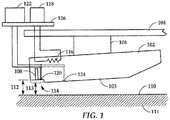
- FIG. 1 a block diagram shows a side view of a magnetic sensor/writer employed in a slider 102 according to an example embodiment.
- This slider 102 may be used as a read/write head of a data storage device, e.g., hard drive.
- a data storage device e.g., hard drive.
- the terms “slider” and “magnetic head” may be used interchangeably.
- the slider 102 is coupled to an arm 104 by way of a suspension 106 that allows some relative motion between the slider 102 and arm 104.
- the slider 102 includes read/write transducers 108 at a trailing edge that are held proximate to a surface 110 of a magnetic recording medium, e.g., disk 111.
- a flying height 112 is maintained between the slider 102 and the surface 110 by a downward force of arm 104. This downward force is counterbalanced by an air cushion that exists between the surface 110 and an air bearing surface 103 of the slider 102 when the disk 111 is rotating.
- a region 114 is a "close point" of the slider 102, which is generally understood to be the closest point of contact between the slider 102 and the magnetic recording medium 111, and generally defines the head-to-media spacing 113.
- the slider 102 may be configured such that a region 114 of the slider 102 can be configurably adjusted during operation in order to finely adjust the head-to-media spacing 113. This is shown in FIG. 1 by dotted line that represents a change in geometry of the region 114. In this example, the geometry change may be induced, in whole or in part, by an increase or decrease in temperature of the region 114.
- the ability to alter shape and deflection magnitude of region 114 in response to temperature change may be due, e.g., to the region 114 being formed from a different material than other parts of the slider 102. In such a case, changes in temperature causes a deformation in this area 114 due to different thermal expansion properties of the respective materials. Selective application of heat to the slider 102 can be used to finely adjust the effective head-to-media spacing 113 of the transducers 108, e.g., as measured between the transducers 108 and media surface 110.
- the slider 102 may include (or otherwise be thermally coupled to) one or more heating elements 116.
- These heating elements 116 e.g., resistance heaters
- the control circuit 118 is coupled to the heating element(s) 116 via an interface 126, that may include physical and electrical conductive paths and connectors, as well as other active or passive circuitry (e.g., noise filters)
- the heating element 116 can be mounted at a variety of locations (e.g., near region 114) and in a manner that minimizes its influence on the aerodynamic properties of the slider.
- Other elements of the slider 102 may also provide heat besides or in addition to the heating element 116.
- a write coil of the read/write transducer 108 may generate sufficient heat to cause configurable deformation of region 114.
- non-thermal devices e.g., piezo-electric devices
- the slider 102 also includes a resistive temperature sensor 120 located at or proximate to region 114.
- This sensor 120 has a temperature coefficient of resistance (TCR) that enables high precision measurements of temperature (or temperature change) at the region 114, and so is sometimes referred to as a TCR sensor.
- TCR temperature coefficient of resistance
- the TCR sensor 120 is coupled to sensor circuitry 122 that communicates with the sensor 120.
- the sensor circuitry 122 may at least include a controller with logic circuitry to perform the functions described herein.
- the circuitry 122 may also include analog or digital circuits for functions such as signal conditioning, digital signal processing, etc.
- the circuitry 122 is shown coupled to the sensor 120 via interface 126, which may include some components (e.g., connectors) in common with heater control 118.
- One or more other TCR sensors may be employed in the slider 102, as represented by sensor 124, which is also coupled to sensor circuitry 122.
- the sensor 124 is disposed in a physically separate location from sensor 120, can be wired separately from sensor 120 or together with sensor 120 (e.g., in series or parallel).
- One or both sensors 120, 124 may be located near the close point within region 114, or at some other location in proximity to the media surface 110.
- the response of the sensor 120 may be used to sense contact with the media 111 during operation.
- some existing contact detection techniques involve applying a DC bias to the sensor 120 and attempting to detect relative changes in resistance as power to the heater 116 is varied. As the close point region 114 comes into contact with the media surface 110, friction may generally cause an increase of the sensor resistance due to an increase in temperature.
- DC resistance measurements are sensitive to noise, and it may require a large number of samples before DC resistance can be estimated. This may make the response of the system unacceptably slow.
- the sensitivity of this technique may significantly depend on the actuation efficiency of the heater 116, which can make it more difficult to consistently set contact threshold over changes in air bearing conditions. For example, a difference in contact response between air bearing designs might purely be from efficiency differences between the heaters.
- RMS root-mean-squared
- This disclosure describes methods and apparatuses that address issues related to existing resistance-based contact detection methods.
- currently-implemented contact detection techniques described above may be sensitive to the location of the resistance element relative to point on the slider that contacts the disk. Because of this location sensitivity, such techniques may not perform acceptably for designs that have dual heaters with different close points.
- the embodiments described herein work with dual heaters each associated with read/write elements and/or different close points.
- each heater may have an associated close point (e.g., read sensor and write transducer) and the sensor may be located away from one or both of the associated close points, yet still be used to detect clearance.
- the embodiments may also work at a variety of skew angles and do not rely on modulation of the sensor signal to declare contact.
- power is applied to the heater 116 with a steady or DC waveform.
- the amplitude of the DC waveform is gradually increased to bring the slider into contact with the disk.
- Contact can be determined by measuring the induced vibrations from contact the head with the disk or by a sudden resistance change due to changing thermal boundary conditions.
- graphs illustrate applied heater power and resulting sensor responses according to an example embodiment.
- a DC power signal is AC-modulated with a sine wave.
- the graph shows two DC offset power levels, P 0 and P 1 .
- the peak-to-peak amplitude of the sine wave does not change for the different power levels DC offset Po, P 1 .
- These input signals may be formed by combining a high frequency (10 kHz to 70 kHz) AC waveform of constant amplitude with the DC waveform.
- the frequency, indicated here by wavelength 204, is also constant at the different DC offset power levels Po, P 1 .
- graph 206 an AC component of a slider-mounted, thermal coefficient of resistance (TCR) sensor is shown.
- This output signal corresponds to the two heater power levels P 0 , P 1 shown in graph 202, and is extracted at a frequency (indicated by wavelength 208) that is the same as that of the input waveform.
- the TCR sensor responds with a resistance change at the same frequency as the AC component of the heater power, indicated here by amplitudes A 0 and A 1 .
- the total sensor output may include a DC offset, as well as other components (e.g., noise), and graph 206 is intended to represent only an AC component at the frequency 208 of interest that is extracted (e.g., filtered).
- the magnitude of the resistance changes from amplitude A 0 and A 1 in response to the changes in heater power.
- graph 206 shows the amplitude increase in response to increasing heater power, it may also decrease in response to increasing heater power. This may be due to whether the sensor has a positive or negative TCR, and other conditions that influence heat transfer proximate the sensor. For example, increasing the heater power increases thermal energy delivered to the sensor, but also brings the resistance element closer to the disk. This closer proximity to the disk changes the heat transfer boundary conditions, and may impact the ultimate resistance of the element used to measure the signals shown in graph 206. As a result, while increases in heater power may generally cause an increase in temperature in parts of the slider, the TCR sensor may see a decrease in temperature due to heat transfer effects (e.g., increase conductivity) of head-to-disk contact.
- heat transfer effects e.g., increase conductivity
- the resistance change occurring at the frequency of AC-modulated power can be measured in the frequency domain.
- DSP digital signal processing
- FFT fast Fourier transform
- DC-only methods may be may be more difficult to implement in a disk drive due to the complexity of the required circuits.
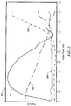
- a graph 300 illustrates measurements of a slider according to an example embodiment.
- the graph 300 includes a number of measurements taken from a slider assembly at different levels of heater power (the horizontal axis).
- the vertical axis indicates signal amplitudes of traces 302-305. It should be noted that the traces 302-305 may be expressed in different units and scales from one another, and are presented to illustrate general trends of various types of measurement.
- Trace 302 is a measure of the static friction between the head and the disk. This trace 302 shows the onset of contact at approximately 120 mW of heater power, with friction increasing steadily up to about 170 mW. Above 170 mW, the friction levels off indicating maximum/full contact between head and disk.
- Trace 303 is a conventional measurement of induced vibrations of the slider.
- Trace 304 is the conventional, DC resistance change of a TCR sensor. Note that this trace 304 decreases at a relatively constant slope up until about 140 mW. The trace 204 changes slope at both 140 mW and 160 mW in response to contact-induced conductivity changes proximate the TCR sensor.
- Trace 305 in FIG. 3 is the amplitude of TCR sensor resistance change measured in the frequency domain at the frequency of the AC waveform modulated onto the heater voltage/current.
- This trace 305 has more variable change in slope through the range than seen in curve 304.
- Trace 305 also shows a clear change at the point of contact that can be used as the contact signature. For example, at around 120 mW, the trace 305 has a point of inflection where the curvature of the trace 305 changes sign. At a local minima around 135 mW, the slope changes from negative to positive. These changes in the trend and direction of the slope can be detected (e.g., by looking a first derivative of the trace 305 as a function of heater power). In this example, trace 305 provides a fairly accurate and detectable representation of contact, e.g., as represented by physical friction measurements shown in trace 302. Relative to trace 305, the DC trace 304 exhibits a relatively weak and late signature of contact.
- the amplitude of resistance change seen in trace 305 exhibits a detectable change at the point of contact. While the shape of this trace 305 may be applicable to the configuration illustrated, it will be appreciated that alternate curves/trends may also be used as a signature of head-to-disk contact. For example, any inflection points or local extremum (e.g., minimum or maximum) of the resistance itself, or derivatives thereof may indicate head-to-disk contact.
- HGA head-gimbal assembly
- This type of clearance detection may not require the resistance element be at the close point and thus works well with dual heater HGAs. This type of clearance detection does not require high levels of advance air bearing (AAB) modulation.
- a slider may include two or more heaters, e.g., one for controlling height of a magnetic reader and another for controlling the height of a magnetic writer.
- a TCR sensor may be employed to operate with one or both heaters at the same or different times.
- the heaters may be modulated with different frequency waveforms, so that two different frequency domain outputs of the TCR sensor can be analyzed.
- multiple TCR sensors may be used, either wired separately or coupled together in parallel and/or series with one another. Signals from these sensors can analyzed separately or combined together as their coupling allows.
- the procedure involves applying 402 a high frequency, AC-modulated heater current to a heater of a magnetic head.
- the heater may be configured to adjust a spacing between the magnetic head and the media.
- the high frequency, AC-modulated heater current may include a DC offset, the DC offset being varied to adjust the spacing.
- a resistance change of a temperature sensor located at a region of proximity to a magnetic media is determined 404.
- the resistance change occurs in response to the heater current.
- This resistance data may optionally be transformed 406 from the time domain to frequency domain.
- At least one of a contact and a clearance/spacing between the magnetic head and the magnetic media is determined 408 based on a frequency-domain signature of the resistance change.
- the frequency domain signature may be measured at the frequency of the heater current.
- the frequency-domain signature may include a local extremum and/or inflection point of the resistance measured in the frequency-domain. In such a case, the local extremum and/or inflection point occurs in response to the contact between the magnetic head and the media.
Landscapes
- Adjustment Of The Magnetic Head Position Track Following On Tapes (AREA)
Applications Claiming Priority (1)
| Application Number | Priority Date | Filing Date | Title |
|---|---|---|---|
| US13/544,559 US8848309B2 (en) | 2012-07-09 | 2012-07-09 | Determining head-to-disk contact and/or spacing using frequency domain signature of a temperature sensor |
Publications (2)
| Publication Number | Publication Date |
|---|---|
| EP2685454A1 EP2685454A1 (en) | 2014-01-15 |
| EP2685454B1 true EP2685454B1 (en) | 2017-09-27 |
Family
ID=48793874
Family Applications (1)
| Application Number | Title | Priority Date | Filing Date |
|---|---|---|---|
| EP13173883.3A Not-in-force EP2685454B1 (en) | 2012-07-09 | 2013-06-26 | Determining head-to-disk contact and/or spacing using frequency domain signature of a temperature sensor |
Country Status (5)
| Country | Link |
|---|---|
| US (1) | US8848309B2 (enExample) |
| EP (1) | EP2685454B1 (enExample) |
| JP (1) | JP5813057B2 (enExample) |
| KR (1) | KR101469586B1 (enExample) |
| CN (1) | CN103544965B (enExample) |
Families Citing this family (19)
| Publication number | Priority date | Publication date | Assignee | Title |
|---|---|---|---|---|
| KR101592195B1 (ko) * | 2010-03-26 | 2016-02-05 | 시게이트 테크놀로지 인터내셔날 | 센서를 이용한 터치-다운 및 헤드/미디어 접촉 검출 방법 및 장치와 이를 적용한 디스크 드라이브 및 저장매체 |
| US8523312B2 (en) | 2010-11-08 | 2013-09-03 | Seagate Technology Llc | Detection system using heating element temperature oscillations |
| KR101496162B1 (ko) | 2010-11-17 | 2015-02-27 | 시게이트 테크놀로지 엘엘씨 | 헤드-매체 간격 및 접촉 검출을 위한 다수의 저항 온도 센서들을 갖는 헤드 트랜스듀서 |
| US9082440B2 (en) * | 2012-07-23 | 2015-07-14 | Seagate Technology Llc | Using first and second resistive sensor bias levels to detect head-to-disk contact and/or clearance |
| US8970978B1 (en) * | 2012-10-22 | 2015-03-03 | Western Digital Technologies, Inc. | Disk drive detecting head touchdown by applying DC+AC control signal to fly height actuator |
| US8638349B1 (en) * | 2013-03-11 | 2014-01-28 | Seagate Technology Llc | Head-medium contact detection using introduced heat oscillation |
| US9117474B1 (en) * | 2014-10-02 | 2015-08-25 | HGST Netherlands B.V. | Implementing write head device for contact detection and spacing sensing |
| US9472225B2 (en) | 2015-02-11 | 2016-10-18 | Seagate Technology Llc | Heat-assisted magnetic recording head-disk clearance setting |
| US9548072B2 (en) * | 2015-02-11 | 2017-01-17 | Seagate Technology Llc | Concurrent modulation and frictional heating head disk contact detection |
| US9595280B2 (en) * | 2015-02-26 | 2017-03-14 | Western Digital Technologies, Inc | Hard disk drive head-disk interface dithering |
| US9443543B1 (en) * | 2015-03-11 | 2016-09-13 | Kabushiki Kaisha Toshiba | Disk storage device and method for controlling head flying height |
| US9245561B1 (en) * | 2015-03-24 | 2016-01-26 | Seagate Technology Llc | Apparatus and method for measuring surface charge of a slider |
| US9564163B2 (en) | 2015-04-03 | 2017-02-07 | Western Digital Technologies, Inc. | Implementing dual partially independent thermal flyheight control (TFC) for hard disk drives |
| US9721603B2 (en) | 2015-09-25 | 2017-08-01 | Seagate Technology Llc | Head-medium contact detection using an oscillating electromagnetic force |
| US9607642B1 (en) | 2016-01-27 | 2017-03-28 | Seagate Technology Llc | Head-medium contact detection using a thermal sensor and surface charge control of a slider |
| US9865292B1 (en) | 2017-02-28 | 2018-01-09 | Seagate Technology Llc | Contact detection using modulated writer coil current for a heat-assisted magnetic recording slider |
| US9786309B1 (en) * | 2017-06-06 | 2017-10-10 | Western Digital Technologies, Inc. | Data storage device detecting minimum stable fly height of a head over a disk |
| US9990950B1 (en) | 2017-07-17 | 2018-06-05 | Seagate Technology Llc | Calibration and adjusting target pre-write clearance offset for a heat-assisted magnetic recording device |
| US10360935B1 (en) | 2018-05-22 | 2019-07-23 | Headway Technologies, Inc. | Dual write heater for slider surface topography control in double perpendicular magnetic recording (PMR) writers |
Family Cites Families (15)
| Publication number | Priority date | Publication date | Assignee | Title |
|---|---|---|---|---|
| US12000A (en) * | 1854-11-28 | James newman | ||
| US7133254B2 (en) | 2003-05-30 | 2006-11-07 | Hitachi Global Storage Technologies Netherlands B.V. | Magnetic recording head with heating device |
| US7092195B1 (en) * | 2004-05-28 | 2006-08-15 | Western Digital (Fremont), Inc. | Method of using a magnetic write head having an internal heater |
| US7180692B1 (en) * | 2005-12-27 | 2007-02-20 | Hitachi Global Storage Technologies Netherlands B.V. | System and method for calibrating and controlling a fly-height actuator in a magnetic recording disk drive |
| JP2008097760A (ja) * | 2006-10-13 | 2008-04-24 | Fujitsu Ltd | ヘッドスライダ用接触判定装置および接触判定方法並びに記憶媒体駆動装置 |
| JP2008112545A (ja) * | 2006-10-31 | 2008-05-15 | Fujitsu Ltd | ヘッドスライダ支持機構の製造方法、ヘッドスライダおよび記憶装置 |
| JP2008186549A (ja) * | 2007-01-31 | 2008-08-14 | Toshiba Corp | 磁気ヘッド、およびこれを備えたディスク装置 |
| JP2009129532A (ja) * | 2007-11-28 | 2009-06-11 | Hitachi Ltd | 磁気ヘッドスライダ及び磁気ディスク装置 |
| US7660068B1 (en) | 2008-09-18 | 2010-02-09 | Hitachi Global Storage Technologies Netherlands B.V. | Method and system for pre-contact detection and active damping of air bearing vibrations in a hard disk drive |
| JP2010129157A (ja) * | 2008-11-29 | 2010-06-10 | Hitachi Global Storage Technologies Netherlands Bv | ディスク・ドライブ、ヘッド・スライダ及びディスク・ドライブにおける記録再生素子のクリアランス制御方法 |
| JP2010205368A (ja) * | 2009-03-05 | 2010-09-16 | Toshiba Storage Device Corp | タッチダウン判定装置、タッチダウン判定方法および磁気ディスク装置 |
| KR101592195B1 (ko) * | 2010-03-26 | 2016-02-05 | 시게이트 테크놀로지 인터내셔날 | 센서를 이용한 터치-다운 및 헤드/미디어 접촉 검출 방법 및 장치와 이를 적용한 디스크 드라이브 및 저장매체 |
| US8562729B2 (en) * | 2010-09-21 | 2013-10-22 | Sanford, L.P. | Highlighting ink formulation comprising an anti-smear agent |
| US8523312B2 (en) * | 2010-11-08 | 2013-09-03 | Seagate Technology Llc | Detection system using heating element temperature oscillations |
| KR101496162B1 (ko) * | 2010-11-17 | 2015-02-27 | 시게이트 테크놀로지 엘엘씨 | 헤드-매체 간격 및 접촉 검출을 위한 다수의 저항 온도 센서들을 갖는 헤드 트랜스듀서 |
-
2012
- 2012-07-09 US US13/544,559 patent/US8848309B2/en active Active
-
2013
- 2013-06-26 EP EP13173883.3A patent/EP2685454B1/en not_active Not-in-force
- 2013-06-28 JP JP2013136342A patent/JP5813057B2/ja not_active Expired - Fee Related
- 2013-07-05 KR KR1020130079092A patent/KR101469586B1/ko not_active Expired - Fee Related
- 2013-07-08 CN CN201310284501.2A patent/CN103544965B/zh active Active
Non-Patent Citations (1)
| Title |
|---|
| None * |
Also Published As
| Publication number | Publication date |
|---|---|
| US8848309B2 (en) | 2014-09-30 |
| JP5813057B2 (ja) | 2015-11-17 |
| CN103544965A (zh) | 2014-01-29 |
| KR101469586B1 (ko) | 2014-12-05 |
| EP2685454A1 (en) | 2014-01-15 |
| KR20140007280A (ko) | 2014-01-17 |
| US20140009851A1 (en) | 2014-01-09 |
| CN103544965B (zh) | 2018-03-30 |
| JP2014017045A (ja) | 2014-01-30 |
Similar Documents
| Publication | Publication Date | Title |
|---|---|---|
| EP2685454B1 (en) | Determining head-to-disk contact and/or spacing using frequency domain signature of a temperature sensor | |
| JP2014017045A5 (enExample) | ||
| US8995076B1 (en) | Head-medium contact detection using electromagnetic attraction | |
| JP5779252B2 (ja) | ヘッドと媒体との間隔および接触を検知するための複数の抵抗温度センサを有するヘッドトランスデューサ | |
| CN104050985B (zh) | 利用引入热振荡的磁头介质接触检测的装置和方法 | |
| US9082440B2 (en) | Using first and second resistive sensor bias levels to detect head-to-disk contact and/or clearance | |
| US8837070B1 (en) | Capacitive clearance detection for a magnetic head | |
| CN101178905A (zh) | 用于磁头滑块接触判断的装置和磁头滑块接触判断方法 | |
| US9093084B2 (en) | Flexible biasing strategy for ground-split TCR sensors | |
| US9607642B1 (en) | Head-medium contact detection using a thermal sensor and surface charge control of a slider | |
| US9595277B2 (en) | Thermally assisted writer protrusion determination and control | |
| JP2008181590A (ja) | 磁気ディスク装置の製造方法 | |
| US9202495B2 (en) | Method and apparatus for detecting proximity contact between a transducer and a medium | |
| JP6266668B2 (ja) | 変調および摩擦加熱によるヘッドとディスクとの接触の同時検出を用いた装置および方法 | |
| US9721603B2 (en) | Head-medium contact detection using an oscillating electromagnetic force | |
| US8238051B2 (en) | Real time monitoring inconsistent operations in a hard disk drive | |
| US8869590B2 (en) | Method and apparatus used for determining friction between slider and rotating data storage medium | |
| US9159348B2 (en) | Systems and methods for clearance monitoring in storage media |
Legal Events
| Date | Code | Title | Description |
|---|---|---|---|
| PUAI | Public reference made under article 153(3) epc to a published international application that has entered the european phase |
Free format text: ORIGINAL CODE: 0009012 |
|
| 17P | Request for examination filed |
Effective date: 20130716 |
|
| AK | Designated contracting states |
Kind code of ref document: A1 Designated state(s): AL AT BE BG CH CY CZ DE DK EE ES FI FR GB GR HR HU IE IS IT LI LT LU LV MC MK MT NL NO PL PT RO RS SE SI SK SM TR |
|
| AX | Request for extension of the european patent |
Extension state: BA ME |
|
| RBV | Designated contracting states (corrected) |
Designated state(s): AL AT BE BG CH CY CZ DE DK EE ES FI FR GB GR HR HU IE IS IT LI LT LU LV MC MK MT NL NO PL PT RO RS SE SI SK SM TR |
|
| 17Q | First examination report despatched |
Effective date: 20160120 |
|
| GRAP | Despatch of communication of intention to grant a patent |
Free format text: ORIGINAL CODE: EPIDOSNIGR1 |
|
| INTG | Intention to grant announced |
Effective date: 20170411 |
|
| GRAS | Grant fee paid |
Free format text: ORIGINAL CODE: EPIDOSNIGR3 |
|
| GRAA | (expected) grant |
Free format text: ORIGINAL CODE: 0009210 |
|
| AK | Designated contracting states |
Kind code of ref document: B1 Designated state(s): AL AT BE BG CH CY CZ DE DK EE ES FI FR GB GR HR HU IE IS IT LI LT LU LV MC MK MT NL NO PL PT RO RS SE SI SK SM TR |
|
| REG | Reference to a national code |
Ref country code: GB Ref legal event code: FG4D |
|
| REG | Reference to a national code |
Ref country code: CH Ref legal event code: EP |
|
| REG | Reference to a national code |
Ref country code: AT Ref legal event code: REF Ref document number: 932678 Country of ref document: AT Kind code of ref document: T Effective date: 20171015 |
|
| REG | Reference to a national code |
Ref country code: IE Ref legal event code: FG4D |
|
| REG | Reference to a national code |
Ref country code: DE Ref legal event code: R096 Ref document number: 602013027065 Country of ref document: DE |
|
| PG25 | Lapsed in a contracting state [announced via postgrant information from national office to epo] |
Ref country code: FI Free format text: LAPSE BECAUSE OF FAILURE TO SUBMIT A TRANSLATION OF THE DESCRIPTION OR TO PAY THE FEE WITHIN THE PRESCRIBED TIME-LIMIT Effective date: 20170927 Ref country code: SE Free format text: LAPSE BECAUSE OF FAILURE TO SUBMIT A TRANSLATION OF THE DESCRIPTION OR TO PAY THE FEE WITHIN THE PRESCRIBED TIME-LIMIT Effective date: 20170927 Ref country code: LT Free format text: LAPSE BECAUSE OF FAILURE TO SUBMIT A TRANSLATION OF THE DESCRIPTION OR TO PAY THE FEE WITHIN THE PRESCRIBED TIME-LIMIT Effective date: 20170927 Ref country code: HR Free format text: LAPSE BECAUSE OF FAILURE TO SUBMIT A TRANSLATION OF THE DESCRIPTION OR TO PAY THE FEE WITHIN THE PRESCRIBED TIME-LIMIT Effective date: 20170927 Ref country code: NO Free format text: LAPSE BECAUSE OF FAILURE TO SUBMIT A TRANSLATION OF THE DESCRIPTION OR TO PAY THE FEE WITHIN THE PRESCRIBED TIME-LIMIT Effective date: 20171227 |
|
| REG | Reference to a national code |
Ref country code: NL Ref legal event code: MP Effective date: 20170927 |
|
| REG | Reference to a national code |
Ref country code: LT Ref legal event code: MG4D |
|
| REG | Reference to a national code |
Ref country code: AT Ref legal event code: MK05 Ref document number: 932678 Country of ref document: AT Kind code of ref document: T Effective date: 20170927 |
|
| PG25 | Lapsed in a contracting state [announced via postgrant information from national office to epo] |
Ref country code: GR Free format text: LAPSE BECAUSE OF FAILURE TO SUBMIT A TRANSLATION OF THE DESCRIPTION OR TO PAY THE FEE WITHIN THE PRESCRIBED TIME-LIMIT Effective date: 20171228 Ref country code: LV Free format text: LAPSE BECAUSE OF FAILURE TO SUBMIT A TRANSLATION OF THE DESCRIPTION OR TO PAY THE FEE WITHIN THE PRESCRIBED TIME-LIMIT Effective date: 20170927 Ref country code: BG Free format text: LAPSE BECAUSE OF FAILURE TO SUBMIT A TRANSLATION OF THE DESCRIPTION OR TO PAY THE FEE WITHIN THE PRESCRIBED TIME-LIMIT Effective date: 20171227 Ref country code: RS Free format text: LAPSE BECAUSE OF FAILURE TO SUBMIT A TRANSLATION OF THE DESCRIPTION OR TO PAY THE FEE WITHIN THE PRESCRIBED TIME-LIMIT Effective date: 20170927 |
|
| PG25 | Lapsed in a contracting state [announced via postgrant information from national office to epo] |
Ref country code: NL Free format text: LAPSE BECAUSE OF FAILURE TO SUBMIT A TRANSLATION OF THE DESCRIPTION OR TO PAY THE FEE WITHIN THE PRESCRIBED TIME-LIMIT Effective date: 20170927 |
|
| PG25 | Lapsed in a contracting state [announced via postgrant information from national office to epo] |
Ref country code: CZ Free format text: LAPSE BECAUSE OF FAILURE TO SUBMIT A TRANSLATION OF THE DESCRIPTION OR TO PAY THE FEE WITHIN THE PRESCRIBED TIME-LIMIT Effective date: 20170927 Ref country code: ES Free format text: LAPSE BECAUSE OF FAILURE TO SUBMIT A TRANSLATION OF THE DESCRIPTION OR TO PAY THE FEE WITHIN THE PRESCRIBED TIME-LIMIT Effective date: 20170927 Ref country code: RO Free format text: LAPSE BECAUSE OF FAILURE TO SUBMIT A TRANSLATION OF THE DESCRIPTION OR TO PAY THE FEE WITHIN THE PRESCRIBED TIME-LIMIT Effective date: 20170927 |
|
| PG25 | Lapsed in a contracting state [announced via postgrant information from national office to epo] |
Ref country code: SM Free format text: LAPSE BECAUSE OF FAILURE TO SUBMIT A TRANSLATION OF THE DESCRIPTION OR TO PAY THE FEE WITHIN THE PRESCRIBED TIME-LIMIT Effective date: 20170927 Ref country code: IT Free format text: LAPSE BECAUSE OF FAILURE TO SUBMIT A TRANSLATION OF THE DESCRIPTION OR TO PAY THE FEE WITHIN THE PRESCRIBED TIME-LIMIT Effective date: 20170927 Ref country code: IS Free format text: LAPSE BECAUSE OF FAILURE TO SUBMIT A TRANSLATION OF THE DESCRIPTION OR TO PAY THE FEE WITHIN THE PRESCRIBED TIME-LIMIT Effective date: 20180127 Ref country code: SK Free format text: LAPSE BECAUSE OF FAILURE TO SUBMIT A TRANSLATION OF THE DESCRIPTION OR TO PAY THE FEE WITHIN THE PRESCRIBED TIME-LIMIT Effective date: 20170927 Ref country code: EE Free format text: LAPSE BECAUSE OF FAILURE TO SUBMIT A TRANSLATION OF THE DESCRIPTION OR TO PAY THE FEE WITHIN THE PRESCRIBED TIME-LIMIT Effective date: 20170927 Ref country code: AT Free format text: LAPSE BECAUSE OF FAILURE TO SUBMIT A TRANSLATION OF THE DESCRIPTION OR TO PAY THE FEE WITHIN THE PRESCRIBED TIME-LIMIT Effective date: 20170927 |
|
| REG | Reference to a national code |
Ref country code: DE Ref legal event code: R097 Ref document number: 602013027065 Country of ref document: DE |
|
| PG25 | Lapsed in a contracting state [announced via postgrant information from national office to epo] |
Ref country code: DK Free format text: LAPSE BECAUSE OF FAILURE TO SUBMIT A TRANSLATION OF THE DESCRIPTION OR TO PAY THE FEE WITHIN THE PRESCRIBED TIME-LIMIT Effective date: 20170927 |
|
| PLBE | No opposition filed within time limit |
Free format text: ORIGINAL CODE: 0009261 |
|
| STAA | Information on the status of an ep patent application or granted ep patent |
Free format text: STATUS: NO OPPOSITION FILED WITHIN TIME LIMIT |
|
| PG25 | Lapsed in a contracting state [announced via postgrant information from national office to epo] |
Ref country code: PL Free format text: LAPSE BECAUSE OF FAILURE TO SUBMIT A TRANSLATION OF THE DESCRIPTION OR TO PAY THE FEE WITHIN THE PRESCRIBED TIME-LIMIT Effective date: 20170927 |
|
| 26N | No opposition filed |
Effective date: 20180628 |
|
| PG25 | Lapsed in a contracting state [announced via postgrant information from national office to epo] |
Ref country code: SI Free format text: LAPSE BECAUSE OF FAILURE TO SUBMIT A TRANSLATION OF THE DESCRIPTION OR TO PAY THE FEE WITHIN THE PRESCRIBED TIME-LIMIT Effective date: 20170927 |
|
| REG | Reference to a national code |
Ref country code: DE Ref legal event code: R119 Ref document number: 602013027065 Country of ref document: DE |
|
| REG | Reference to a national code |
Ref country code: CH Ref legal event code: PL |
|
| REG | Reference to a national code |
Ref country code: BE Ref legal event code: MM Effective date: 20180630 |
|
| REG | Reference to a national code |
Ref country code: IE Ref legal event code: MM4A |
|
| PG25 | Lapsed in a contracting state [announced via postgrant information from national office to epo] |
Ref country code: MC Free format text: LAPSE BECAUSE OF FAILURE TO SUBMIT A TRANSLATION OF THE DESCRIPTION OR TO PAY THE FEE WITHIN THE PRESCRIBED TIME-LIMIT Effective date: 20170927 Ref country code: LU Free format text: LAPSE BECAUSE OF NON-PAYMENT OF DUE FEES Effective date: 20180626 |
|
| PG25 | Lapsed in a contracting state [announced via postgrant information from national office to epo] |
Ref country code: CH Free format text: LAPSE BECAUSE OF NON-PAYMENT OF DUE FEES Effective date: 20180630 Ref country code: LI Free format text: LAPSE BECAUSE OF NON-PAYMENT OF DUE FEES Effective date: 20180630 Ref country code: FR Free format text: LAPSE BECAUSE OF NON-PAYMENT OF DUE FEES Effective date: 20180630 Ref country code: IE Free format text: LAPSE BECAUSE OF NON-PAYMENT OF DUE FEES Effective date: 20180626 Ref country code: DE Free format text: LAPSE BECAUSE OF NON-PAYMENT OF DUE FEES Effective date: 20190101 |
|
| PG25 | Lapsed in a contracting state [announced via postgrant information from national office to epo] |
Ref country code: BE Free format text: LAPSE BECAUSE OF NON-PAYMENT OF DUE FEES Effective date: 20180630 |
|
| PGFP | Annual fee paid to national office [announced via postgrant information from national office to epo] |
Ref country code: GB Payment date: 20190524 Year of fee payment: 7 |
|
| PG25 | Lapsed in a contracting state [announced via postgrant information from national office to epo] |
Ref country code: MT Free format text: LAPSE BECAUSE OF NON-PAYMENT OF DUE FEES Effective date: 20180626 |
|
| PG25 | Lapsed in a contracting state [announced via postgrant information from national office to epo] |
Ref country code: TR Free format text: LAPSE BECAUSE OF FAILURE TO SUBMIT A TRANSLATION OF THE DESCRIPTION OR TO PAY THE FEE WITHIN THE PRESCRIBED TIME-LIMIT Effective date: 20170927 |
|
| PG25 | Lapsed in a contracting state [announced via postgrant information from national office to epo] |
Ref country code: PT Free format text: LAPSE BECAUSE OF FAILURE TO SUBMIT A TRANSLATION OF THE DESCRIPTION OR TO PAY THE FEE WITHIN THE PRESCRIBED TIME-LIMIT Effective date: 20170927 Ref country code: HU Free format text: LAPSE BECAUSE OF FAILURE TO SUBMIT A TRANSLATION OF THE DESCRIPTION OR TO PAY THE FEE WITHIN THE PRESCRIBED TIME-LIMIT; INVALID AB INITIO Effective date: 20130626 |
|
| PG25 | Lapsed in a contracting state [announced via postgrant information from national office to epo] |
Ref country code: CY Free format text: LAPSE BECAUSE OF FAILURE TO SUBMIT A TRANSLATION OF THE DESCRIPTION OR TO PAY THE FEE WITHIN THE PRESCRIBED TIME-LIMIT Effective date: 20170927 Ref country code: MK Free format text: LAPSE BECAUSE OF NON-PAYMENT OF DUE FEES Effective date: 20170927 |
|
| PG25 | Lapsed in a contracting state [announced via postgrant information from national office to epo] |
Ref country code: AL Free format text: LAPSE BECAUSE OF FAILURE TO SUBMIT A TRANSLATION OF THE DESCRIPTION OR TO PAY THE FEE WITHIN THE PRESCRIBED TIME-LIMIT Effective date: 20170927 |
|
| GBPC | Gb: european patent ceased through non-payment of renewal fee |
Effective date: 20200626 |
|
| PG25 | Lapsed in a contracting state [announced via postgrant information from national office to epo] |
Ref country code: GB Free format text: LAPSE BECAUSE OF NON-PAYMENT OF DUE FEES Effective date: 20200626 |