US9202495B2 - Method and apparatus for detecting proximity contact between a transducer and a medium - Google Patents
Method and apparatus for detecting proximity contact between a transducer and a medium Download PDFInfo
- Publication number
- US9202495B2 US9202495B2 US11/799,204 US79920407A US9202495B2 US 9202495 B2 US9202495 B2 US 9202495B2 US 79920407 A US79920407 A US 79920407A US 9202495 B2 US9202495 B2 US 9202495B2
- Authority
- US
- United States
- Prior art keywords
- magnetic head
- disc
- storage medium
- head slider
- transducer
- Prior art date
- Legal status (The legal status is an assumption and is not a legal conclusion. Google has not performed a legal analysis and makes no representation as to the accuracy of the status listed.)
- Active, expires
Links
Images


Classifications
-
- G—PHYSICS
- G11—INFORMATION STORAGE
- G11B—INFORMATION STORAGE BASED ON RELATIVE MOVEMENT BETWEEN RECORD CARRIER AND TRANSDUCER
- G11B5/00—Recording by magnetisation or demagnetisation of a record carrier; Reproducing by magnetic means; Record carriers therefor
- G11B5/48—Disposition or mounting of heads or head supports relative to record carriers ; arrangements of heads, e.g. for scanning the record carrier to increase the relative speed
- G11B5/58—Disposition or mounting of heads or head supports relative to record carriers ; arrangements of heads, e.g. for scanning the record carrier to increase the relative speed with provision for moving the head for the purpose of maintaining alignment of the head relative to the record carrier during transducing operation, e.g. to compensate for surface irregularities of the latter or for track following
-
- G—PHYSICS
- G11—INFORMATION STORAGE
- G11B—INFORMATION STORAGE BASED ON RELATIVE MOVEMENT BETWEEN RECORD CARRIER AND TRANSDUCER
- G11B5/00—Recording by magnetisation or demagnetisation of a record carrier; Reproducing by magnetic means; Record carriers therefor
- G11B5/127—Structure or manufacture of heads, e.g. inductive
- G11B5/31—Structure or manufacture of heads, e.g. inductive using thin films
- G11B5/3109—Details
- G11B5/313—Disposition of layers
- G11B5/3133—Disposition of layers including layers not usually being a part of the electromagnetic transducer structure and providing additional features, e.g. for improving heat radiation, reduction of power dissipation, adaptations for measurement or indication of gap depth or other properties of the structure
- G11B5/3136—Disposition of layers including layers not usually being a part of the electromagnetic transducer structure and providing additional features, e.g. for improving heat radiation, reduction of power dissipation, adaptations for measurement or indication of gap depth or other properties of the structure for reducing the pole-tip-protrusion at the head transducing surface, e.g. caused by thermal expansion of dissimilar materials
-
- G—PHYSICS
- G11—INFORMATION STORAGE
- G11B—INFORMATION STORAGE BASED ON RELATIVE MOVEMENT BETWEEN RECORD CARRIER AND TRANSDUCER
- G11B5/00—Recording by magnetisation or demagnetisation of a record carrier; Reproducing by magnetic means; Record carriers therefor
- G11B5/455—Arrangements for functional testing of heads; Measuring arrangements for heads
-
- G—PHYSICS
- G11—INFORMATION STORAGE
- G11B—INFORMATION STORAGE BASED ON RELATIVE MOVEMENT BETWEEN RECORD CARRIER AND TRANSDUCER
- G11B5/00—Recording by magnetisation or demagnetisation of a record carrier; Reproducing by magnetic means; Record carriers therefor
- G11B5/48—Disposition or mounting of heads or head supports relative to record carriers ; arrangements of heads, e.g. for scanning the record carrier to increase the relative speed
- G11B5/58—Disposition or mounting of heads or head supports relative to record carriers ; arrangements of heads, e.g. for scanning the record carrier to increase the relative speed with provision for moving the head for the purpose of maintaining alignment of the head relative to the record carrier during transducing operation, e.g. to compensate for surface irregularities of the latter or for track following
- G11B5/60—Fluid-dynamic spacing of heads from record-carriers
- G11B5/6005—Specially adapted for spacing from a rotating disc using a fluid cushion
- G11B5/6011—Control of flying height
- G11B5/6064—Control of flying height using air pressure
-
- G—PHYSICS
- G11—INFORMATION STORAGE
- G11B—INFORMATION STORAGE BASED ON RELATIVE MOVEMENT BETWEEN RECORD CARRIER AND TRANSDUCER
- G11B5/00—Recording by magnetisation or demagnetisation of a record carrier; Reproducing by magnetic means; Record carriers therefor
- G11B5/48—Disposition or mounting of heads or head supports relative to record carriers ; arrangements of heads, e.g. for scanning the record carrier to increase the relative speed
- G11B5/58—Disposition or mounting of heads or head supports relative to record carriers ; arrangements of heads, e.g. for scanning the record carrier to increase the relative speed with provision for moving the head for the purpose of maintaining alignment of the head relative to the record carrier during transducing operation, e.g. to compensate for surface irregularities of the latter or for track following
- G11B5/60—Fluid-dynamic spacing of heads from record-carriers
- G11B5/6005—Specially adapted for spacing from a rotating disc using a fluid cushion
- G11B5/6011—Control of flying height
- G11B5/607—Control of flying height using thermal means
-
- G—PHYSICS
- G11—INFORMATION STORAGE
- G11B—INFORMATION STORAGE BASED ON RELATIVE MOVEMENT BETWEEN RECORD CARRIER AND TRANSDUCER
- G11B5/00—Recording by magnetisation or demagnetisation of a record carrier; Reproducing by magnetic means; Record carriers therefor
- G11B5/10—Structure or manufacture of housings or shields for heads
- G11B5/105—Mounting of head within housing or assembling of head and housing
-
- G—PHYSICS
- G11—INFORMATION STORAGE
- G11B—INFORMATION STORAGE BASED ON RELATIVE MOVEMENT BETWEEN RECORD CARRIER AND TRANSDUCER
- G11B5/00—Recording by magnetisation or demagnetisation of a record carrier; Reproducing by magnetic means; Record carriers therefor
- G11B5/48—Disposition or mounting of heads or head supports relative to record carriers ; arrangements of heads, e.g. for scanning the record carrier to increase the relative speed
- G11B5/54—Disposition or mounting of heads or head supports relative to record carriers ; arrangements of heads, e.g. for scanning the record carrier to increase the relative speed with provision for moving the head into or out of its operative position or across tracks
- G11B5/55—Track change, selection or acquisition by displacement of the head
- G11B5/5521—Track change, selection or acquisition by displacement of the head across disk tracks
- G11B5/5552—Track change, selection or acquisition by displacement of the head across disk tracks using fine positioning means for track acquisition separate from the coarse (e.g. track changing) positioning means
- G11B5/5556—Track change, selection or acquisition by displacement of the head across disk tracks using fine positioning means for track acquisition separate from the coarse (e.g. track changing) positioning means with track following after a "seek"
- G11B5/556—Track change, selection or acquisition by displacement of the head across disk tracks using fine positioning means for track acquisition separate from the coarse (e.g. track changing) positioning means with track following after a "seek" control circuits therefor
Definitions
- the present disclosure relates to detection or measurement of changes in head-medium spacing in a device in which a transducer is positioned in close proximity to an associated medium, such as a read/write head in a data storage device.
- HMS Head-Media Spacing
- Some data storage systems employ active clearance control, wherein one or more elements of the transducer or the transducer's support structure are movable relative to the medium surface.
- microactuators have been positioned along the transducer's suspension for displacing the transducer vertically relative to the medium.
- thermal pole tip protrusion have been used for active clearance control. Differences in thermal coefficients of expansion between the materials used for forming the write pole and other elements of the transducing head can cause movement of the write pole relative to the other elements with changes in temperature.
- protrusion of the write pole relative to the other elements can be controlled to thereby control the spacing between the write pole and the medium surface.
- thermal pole tip protrusion can be increased by elevating the temperature of the write pole material by some method, such as by turning on or elevating a write current.
- Active clearance control methods adjust the temperature of the write pole based on some measure of the Head-Media Spacing.
- a variety of methods have been used for detecting or measuring the Head-Media Spacing.
- U.S. Pat. No. 7,038,875 describes a dynamic measurement of Head-Media Spacing modulation, which is based on a harmonic ratio measurement of the recording head read-back signal. Typical harmonic ratio measurements need to be calibrated at zero spacing, which requires the write pole to contact the medium surface. As the write pole is actuated toward the medium surface, contact has been detected by several methods.
- One current technique for rotating-disc type medium is to detect off-track movement of the head caused by friction at the contact when the head is flying at a non-zero skew angle.
- friction can cause undesirable wear on the head and/or recording surface.
- the write pole dimension can be less than 200 nanometers. It has been found that the tip of the write pole is often severally worn before the contact can be reliably detected. Therefore a dedicated feature, such as a contact pad, has been fabricated on the head to generate enough interaction at the contact to allow detection of the contact while preventing the write pole tip from being worn out.
- the contact pad is typically manufactured using different materials (e.g., non-magnetic) than the write pole and is typically positioned at a certain distance away from the write pole. Therefore, significant height variations can exist between the write pole and the contact pad after typical lapping and milling processes. These variations are becoming a major limitation for active clearance control since these variations often cannot be compensated by the write pole heater.
- a further limitation of the current detection technique is that the technique cannot detect the contact when the head is oriented at a zero skew angle relative to the tangential velocity of the disc since there is no off-track movement of the head caused by the friction at the contact.
- alternative contact detection techniques are desired that may be capable of reliably detecting contact at the write pole without significant wear and that do not require a contact pad and its resulting head medium spacing loss caused by height variations between the write pole and the contact pad.
- Embodiments of the present disclosure provide solutions to these and other problems, and offer other advantages over the prior art.
- An embodiment is directed to a method, which includes positioning a transducer relative to a track of a data storage medium and inducing lateral modulation of transducer the relative to the track.
- An element of the transducer is actuated toward the storage medium during the lateral modulation, and atomic interaction is detected between the element and the storage medium because of a change in a response to the lateral modulation of the transducer due to the atomic interaction.
- Another embodiment is directed to a method, which includes positioning a transducer relative to a medium, wherein the medium moves relative to the transducer along a direction of motion, and inducing lateral modulation of the transducer relative to the direction of motion. An element of the transducer is actuated toward the medium during the lateral modulation. The method further includes monitoring a change in response to the lateral modulation of the transducer due to atomic interaction between the element and the medium.
- a further embodiment is directed to a method, which includes: detecting atomic interaction between a transducer and a storage medium by monitoring a response to induced lateral modulation of the transducer relative to the storage medium; and generating an output signal indicative of a zero spacing condition between the transducer and the storage medium based on the response.
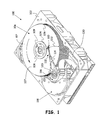
- FIG. 1 is an isometric view of an example of a data storage device in which one or more embodiments of the present disclosure are useful.
- FIG. 2 is a diagram, which schematically illustrates a proximity contact detection apparatus according to an embodiment of the present disclosure.
- FIG. 3 is a block diagram illustrating an algorithm for detecting a zero or near zero spacing condition according to an embodiment of the disclosure.
- FIG. 4 is a waveform diagram illustrating an example of a change to the modulation response of a transducer due to changes in inter-atomic forces between the transducer and a respective medium.
- FIG. 5 is a simplified diagram of a transducer having a dedicated acoustic emission film sensor applied to a surface of the transducer, according to an embodiment of the disclosure.
- An embodiment of the present disclosure provides a method and apparatus for detecting a zero or near zero spacing condition between a transducer and a data storage medium. This detection can be used, for example, to calibrate active clearance control of the transducer.
- FIG. 1 is an isometric view of an example of a data storage device 100 in which one or more embodiments of the present disclosure are useful. Embodiments are also useful in other types of data storage and non-data storage devices in which techniques are desired for detecting contact between a transducer and a medium that move relative to one another.
- data storage device 100 includes a typical disc drive having a housing with a base 102 and a top cover (not shown).
- Data storage device 100 further includes a disc pack 106 , which is mounted on a spindle motor (not shown) by a disc clamp 108 .
- Disc pack 106 includes a plurality of individual discs 107 , which are mounted for co-rotation about central axis 109 .
- Each disc surface has an associated transducer 110 , generally known as a disc head slider, which is mounted to disc drive 100 for communication with the disc surface.
- transducers 110 are supported by suspensions 112 which are in turn attached to track accessing arms 114 of an actuator 116 .
- Voice coil motor 118 rotates actuator 116 with its attached transducers 110 about a pivot shaft 120 to position transducers 110 over a desired data track along an accurate path 122 between a disc inner diameter 124 and a disc outer diameter 126 .
- Voice coil motor 118 is driven by a servo controller within electronics 130 based on signals generated by transducers 110 and a host computer (not shown).
- the transducer supports one or more heads, such as a read head and/or a write head that communicates with the respective disc surface. Data is stored on the disc surface as a plurality of transitions in magnetic orientation along one or more circular, concentric tracks. As each transducers 110 passes over the magnetic transitions, the read head generates a readback signal, which is sent to a read channel within electronics 130 . The read channel recovers the desired data from the readback signal. Similarly, electronics 130 includes a write channel that supplies a write signal to the write head for writing data to the disc surface.
- Some data storage systems employ active clearance control, wherein one or more elements of the transducer or the transducer's support structure (such as a portion of suspension 112 ) are movable vertically relative to the disc surface. Active clearance control utilizes some measure of the spacing between the transducer and the disc surface in order to control and/or limit dynamic variations in the spacing.
- Head-Media Spacing modulation is a measure of the variations in displacement of the read and/or write head (or other element of the transducer) relative to the medium. Head-Media Spacing modulation is often caused by media waviness, disc clamping distortion, write current induced pole tip protrusion, micro-actuator induced modulation, as well as other factors. A variety of techniques can be used to measure Head-Media Spacing modulation. As described in U.S. Pat. No. 7,038,875, which is assigned to Seagate Technology LLC, the readback signal contains a fundamental frequency and higher harmonics. The ratio of the harmonic components is sensitive to Head-Media Spacing but less sensitive to environmental effects.
- a data acquisition and processing system which is coupled to the read channel, processes the data over a selected sampling interval.
- the frequency spectrum of the readback signal over the selected sampling interval is calculated.
- the frequency spectrum and higher harmonics are calculated using fast Fourier transforms. This frequency calculation typically includes a determination of the instantaneous amplitude of the fundamental and harmonic frequency of the readback signal over the sampling interval.
- the system calculates the harmonic ratio by dividing the instantaneous amplitude of the fundamental frequency of the readback signal by the instantaneous amplitude of one of the harmonic frequencies of the readback signal.
- a dynamic harmonic ratio of the readback signal can be generated.
- the dynamic harmonic ratio can be used to calculate the head-media spacing modulation as a function of time.
- Typical harmonic ratio measurements need to be calibrated at zero spacing.
- An embodiment of the present disclosure is directed to a method and apparatus for detecting or predicting “contact” before a real solid-to-solid contact event occurs.
- the detection of a zero spacing condition can be used to calibrate any type of activate clearance control algorithm, such as the harmonic ratio measurements discussed above, and can be used for purposes other than active clearance control.
- the method allows reliable detection of head-disc contact at a controlled spacing with little or no wear on the head or disc.
- FIG. 2 is a diagram, which schematically illustrates a proximity contact detection apparatus according to an embodiment of the present disclosure.
- the same reference numerals are used in FIG. 2 as were used in FIG. 1 for the same or similar elements.
- Data acquisition and processing system (DAPS) 140 implements an algorithm 160 (shown in FIG. 3 ) for inducing and then detecting contact between an element 142 of transducer 110 and the surface of disc 107 .
- element 142 corresponds to a read head or a write head.
- element 142 can be any element of transducer 110 .
- the size and protrusion of element 142 is greatly exaggerated in FIG. 2 for clarity.
- Data acquisition and processing system 140 can be implemented as part of electronics 130 within data storage system 100 or can be implemented as a separate component that is connected to the data storage system, such as an application in a host or remote computer, for example.
- algorithm 160 instructs the servo control system within electronics 130 to position element 142 relative to a selected track 144 .
- Track 144 can be pre-written prior to the execution of algorithm 160 or can be written during a step of the algorithm.
- transducer 110 is positioned relative to track 144
- disc 107 rotates about a central axis 146 in a direction indicated by arrow 147 .
- step 164 as transducer 110 follows track 144 , algorithm 160 instructs the servo control system to modulate the position of transducer 110 laterally, as shown by arrow 149 , relative to the longitudinal direction of the track at a certain modulation frequency.
- Any suitable method or apparatus can be used to laterally modulate transducer 110 .
- suspension 112 includes both a primary actuator, such as voice coil motor 118 (shown in FIG. 1 ) and a secondary, microactuator 148 located somewhere on suspension 112
- the algorithm can use microactuator 148 to induce the forced lateral modulation.
- Any suitable type of microactuator can be used, and the microactuator can be located at or coupled to any position along suspension 112 .
- the primary voice coil motor 118 can be used to induce the lateral modulation. If the calibration is being performed on a spin stand tester, the lateral modulation can be induced by an actuator arm on the spin stand tester.
- the modulation frequency is selected to be at the vicinity of the intrinsic resonant frequency of the actuator on the suspension that induces the lateral modulation, such as microactuator 148 .
- the module modulation frequency can be set within a range of ⁇ 5% of the intrinsic resonant frequency of microactuator 148 . However, values outside of that range can be used as well.
- the modulation frequency can be determined by a finite element model (FEM) or through a frequency response experiment, for example. Also, the resonant frequency can be based on other elements of suspension 112 .
- step 166 as transducer 110 modulates laterally about track 144 , algorithm 160 actuates an element of transducer 110 , such as element 142 , toward the disc surface.
- Arrows 150 represent vertical actuation of the element relative to the surface of disc 107 .
- the element can be actuated independently or with any other element of transducer 110 or suspension 112 .
- the element can be actuated toward the disc surface in a variety of ways, depending upon the structure of transducer 110 and suspension 112 .
- microactuator 148 can include a vertical displacement feature for displacing transducer 110 vertically relative to the surface of disc 107 .
- the vertical displacement feature can be integrated with the lateral displacement feature used to laterally modulate transducer 110 or can be a separate microactuating element that can be positioned or coupled to any suitable location along suspension 112 or transducer 110 .
- Any suitable type of microactuator can be used for vertically actuating the transducer and/or one or more elements of the transducer or suspension, such as a piezoelectric microactuator.
- thermal pole tip protrusion can be used for vertical actuation, either as an alternative to or in combination with microactuator 148 .
- Differences in thermal coefficients of expansion between the materials used to form elements of the transducer, such as the write pole or the read head, and other elements of transducer 110 can cause movement of these elements relative to the other elements with changes in temperature.
- the movement can be controlled in order to control the vertical positions of the elements and their spacing from the disc surface.
- thermal pole tip protrusion of the write pole can be controlled to actuate the write pole toward the disc surface by controlling the temperature of the write pole material.
- the temperature can be altered by any suitable method or apparatus.
- the temperature can be elevated by turning on or elevating current through the write pole.
- a separate heating element can be applied to transducer 110 in the vicinity of or in contact with the write head or the read head. Current through the heating element can be controlled to vary the resulting temperature of the element being actuated.
- a heating element 152 can be applied to the trailing surface of transducer 110 .
- Other methods of actuating an element of transducer 110 relative to the surface of disc 107 can be used in alternative embodiments.
- step 168 as element 142 (or the entire transducer 110 ) is actuated toward the disc surface, data acquisition and processing system 140 monitors a signal 153 that is representative of the modulation response of transducer 110 to the forced lateral modulation 149 .
- inter-atomic Van der Waals
- the inter-atomic force becomes stronger as the atoms of the two surfaces come closer together.
- Another force that can act on transducer 110 before solid-to-solid contact occurs is a capillary force exerted by a lubrication layer on disc 107 .
- the amplitude of the transducer modulation response to the forced lateral modulation 149 decreases due to the action of the inter-atomic forces. Also, the frequency and phase of the transducer modulation response vary because of the increasing molecular interaction. One or more of these effects can be monitored in a variety of ways in order to detect a zero or near zero spacing condition between transducer 110 and disc 107 with little or no wear to the transducer elements or to disc 107 .
- FIG. 4 is a waveform diagram illustrating an example of a change to the modulation response of transducer 110 as the transducer nears the disc surface.
- Axis 180 represents time, and axis 181 represents amplitude.
- Waveform 182 represents the forced lateral modulation applied to transducer 110 .
- Waveform 183 represents the modulation response of transducer 110 .
- Arrow 184 indicates the response when the transducer is relatively far away from contact with the disc surface.
- Arrow 185 indicates the response when the transducer is in proximity of contact with the disc surface. As the head-media spacing decreases, the amplitude of response 183 decreases, and the response exhibits a shift in phase and frequency.
- the changes in amplitude, frequency, phase and also harmonics of the modulation response can be monitored individually or can be monitored simultaneously. While amplitude detection can be relatively easy to implement, phase detection may be more sensitive since the change in amplitude vibration does not occur instantaneously with a change in the pole tip and disc interaction. Frequency and its high harmonic detection are believed to achieve even higher sensitivity than phase detection. For example, when monitoring the amplitude and looking into a fixed frequency in the frequency domain, the harmonics of the base frequency are also readily available. An algorithm can be created to use the ratios between harmonics to improve the signal to noise ratio.
- a variety of different methods and apparatus can be used to monitor the modulation response and thereby generate signal 153 .
- the response of transducer 110 or any other element of suspension 112 can be measured through the readback signal generated by the read transducer.
- data acquisition and processing system 140 can monitor the amplitude of the readback signal. As the position of the read head is modulated relative to the track center, the amplitude of the readback signal becomes modulated with increasing and decreasing magnetic field strength. The modulation response of the transducer therefore results in a modulation of the readback signal amplitude. One or more characteristics of the readback signal are therefore representative of the lateral modulation response.
- system 140 can monitor a characteristic of a read back signal generated by the transducer in response to a data pattern stored on a track, wherein the characteristic includes at least one element of the group comprising or consisting of amplitude, phase, frequency, both amplitude and phase, both phase and frequency, both amplitude and frequency, each one of amplitude, phase and frequency, and any other suitable combination of these and other characteristics.
- a dedicated sensor can be built on or arranged relative to transducer 110 or suspension 112 .
- an acoustic emission (AE) sensor such as a piezoelectric film element can be built on transducer 110 for monitoring the lateral modulation frequency response.
- FIG. 5 is a simplified diagram of a transducer 110 having a dedicated acoustic emission film sensor 190 applied to a surface of transducer 110 .
- Sensor 190 can be applied to any suitable surface or area of transducer 110 , such as along its trailing surface.
- the modulation response can be measured by monitoring an electrical characteristic, such as capacitance, of the PZT element of the microactuator.
- the PZT element can be connected as one arm of a capacitive bridge.
- Data acquisition and processing system 140 can monitor modulation of the electrical characteristic of the PZT element due to the modulation response of transducer 110 .
- the microactuator can include the same microactuator element, such as microactuator 148 in FIG. 2 , that is used to induce the lateral modulation or to provide vertical actuation toward the disc surface.
- sensor 192 can be used to remotely monitor the modulation response and provide a representative signal 193 to data acquisition and processing system 140 .
- Sensor 192 can remotely monitor through a variety of technologies using electromagnetic radiation, for example.
- sensor 192 includes an interferometer, which can be mounted internal or external to data storage system 100 . The interferometer does not physically contact suspension 112 but is in optical communication with an element of suspension 112 , such as transducer 110 .
- the system outputs a signal indicative of the zero or near zero spacing condition, at step 170 .
- Any suitable criteria can be used for identifying a zero or near zero spacing condition or to predict an imminent solid-to-solid contact.
- the characteristics of the particular signal or signals being monitored can be correlated to particular inter-atomic and capillary forces between the transducer and the disc surface.
- a threshold can be set at which the inter-atomic and/or capillary forces indicate or predict a zero spacing condition. This threshold can be set at any desired level.
- the methods and apparatus discussed above can be used to detect the interaction of an inter-atomic force at near zero spacing and before solid contact occurs. This allows detection and calibration of a zero spacing condition while eliminating wear at the contact point and the need of a contact pad. Therefore, head-medium spacing loss caused by height variations between the write pole and such a contact pad can also be eliminated.
- the method and apparatus can be used within a data storage device or at a spin stand tester, for example.
Landscapes
- Physics & Mathematics (AREA)
- Electromagnetism (AREA)
- Engineering & Computer Science (AREA)
- Manufacturing & Machinery (AREA)
- Supporting Of Heads In Record-Carrier Devices (AREA)
Abstract
Description
HR=Ce−4π(d/λ) Eq. 1
where HR is harmonic ratio, C is a constant, λ1 is the wavelength of the readback signal, which is equal to the disc velocity divided by the fundamental frequency, and d is head media spacing. Accordingly, head media spacing modulation can be calculated by calculating the ratio of the instantaneous amplitude of the fundamental frequency of the readback signal to the instantaneous amplitude of one of the harmonic frequencies of the readback signal. Head media spacing modulation is can be defined by:
δd=(−λ/4π)δLn(HR) Eq. 2
Claims (16)
Priority Applications (1)
| Application Number | Priority Date | Filing Date | Title |
|---|---|---|---|
| US11/799,204 US9202495B2 (en) | 2007-05-01 | 2007-05-01 | Method and apparatus for detecting proximity contact between a transducer and a medium |
Applications Claiming Priority (1)
| Application Number | Priority Date | Filing Date | Title |
|---|---|---|---|
| US11/799,204 US9202495B2 (en) | 2007-05-01 | 2007-05-01 | Method and apparatus for detecting proximity contact between a transducer and a medium |
Publications (2)
| Publication Number | Publication Date |
|---|---|
| US20080273260A1 US20080273260A1 (en) | 2008-11-06 |
| US9202495B2 true US9202495B2 (en) | 2015-12-01 |
Family
ID=39939325
Family Applications (1)
| Application Number | Title | Priority Date | Filing Date |
|---|---|---|---|
| US11/799,204 Active 2030-08-12 US9202495B2 (en) | 2007-05-01 | 2007-05-01 | Method and apparatus for detecting proximity contact between a transducer and a medium |
Country Status (1)
| Country | Link |
|---|---|
| US (1) | US9202495B2 (en) |
Cited By (1)
| Publication number | Priority date | Publication date | Assignee | Title |
|---|---|---|---|---|
| US10410661B1 (en) | 2018-10-26 | 2019-09-10 | Seagate Technology Llc | Head media spacing using multiple readers |
Families Citing this family (5)
| Publication number | Priority date | Publication date | Assignee | Title |
|---|---|---|---|---|
| US20100157765A1 (en) * | 2008-12-19 | 2010-06-24 | Seagate Technology Llc | Collection of readback signal modulation data |
| US8730611B2 (en) * | 2011-02-28 | 2014-05-20 | Seagate Technology Llc | Contact detection |
| US9047902B1 (en) | 2011-06-15 | 2015-06-02 | Western Digital (Fremont), Llc | Touchdown sensor having a more stable crystal structure for use in hard disk drives |
| US8837081B1 (en) | 2011-12-06 | 2014-09-16 | Western Digital (Fremont), Llc | Laminated touchdown sensor for hard disk drives |
| US9171581B2 (en) | 2013-03-08 | 2015-10-27 | Seagate Technology Llc | Friction force measurement assembly and method |
Citations (33)
| Publication number | Priority date | Publication date | Assignee | Title |
|---|---|---|---|---|
| US4777544A (en) | 1986-08-15 | 1988-10-11 | International Business Machine Corporation | Method and apparatus for in-situ measurement of head/recording medium clearance |
| US4835361A (en) | 1986-07-21 | 1989-05-30 | Magnetic Peripherals Inc. | Laser machining for producing very small parts |
| US4910621A (en) | 1987-02-09 | 1990-03-20 | Kabushiki Kaisha Toshiba | Magnetic head device having sloped sliding surface which is formed thermally curved |
| US4914868A (en) | 1988-09-28 | 1990-04-10 | International Business Machines Corporation | Lapping control system for magnetic transducers |
| US5266769A (en) | 1992-02-25 | 1993-11-30 | International Business Machines Corporation | Process for independent control of crown and camber for magnetic head slider |
| US5442850A (en) | 1993-11-01 | 1995-08-22 | International Business Machines Corporation | Magnetic head slider process |
| US5636088A (en) | 1993-11-25 | 1997-06-03 | Kabushiki Kaisha Toshiba | Head assembly controlling distortion due to temperature variation and disk apparatus using the head assembly |
| US5808977A (en) * | 1995-09-06 | 1998-09-15 | Hitachi, Ltd. | Tracking method and recording means thereby |
| US5936806A (en) | 1998-03-06 | 1999-08-10 | International Business Machines Corporation | Flying head slider and suspension assembly with stress relief for controlling slider crown thermal sensitivity |
| US5949627A (en) | 1993-02-19 | 1999-09-07 | Read-Rite Corporation | Thin film magnetic head with stress relief layering |
| US5953125A (en) | 1995-09-01 | 1999-09-14 | Zygo Corporation | Optical gap measuring apparatus and method |
| US6008640A (en) * | 1997-04-28 | 1999-12-28 | Seagate Technology, Inc. | Detection and measurement of head disc interference using read back signal (without acoustic emission sensor or laser doppler vibrometer) |
| US6057975A (en) | 1994-10-11 | 2000-05-02 | Seagate Technology, Inc. | Fly height adjustment in magnetic storage system |
| US6073337A (en) | 1996-06-12 | 2000-06-13 | Seagate Technology, Inc. | Compressive stress treatment method for controlling curvature of a hydrodynamic bearing slider |
| US6108170A (en) | 1998-11-10 | 2000-08-22 | International Business Machines Corporation | Slider row with segmented scribe lines for individual control curvature of sliders in the row |
| US6268976B1 (en) | 1996-12-12 | 2001-07-31 | Maxtor Corporation | Disk drive which detects head flying height using a linearly increasing frequency data pattern |
| US6321440B1 (en) | 1998-11-10 | 2001-11-27 | International Business Machines Corporation | Method for adjusting curvature of magnetic read/write head sliders |
| US6466409B1 (en) | 1998-03-18 | 2002-10-15 | International Business Machines Corporation | Negative pressure slider with temperature-insensitive flying height for disk storage device |
| US6466392B1 (en) | 1998-09-14 | 2002-10-15 | Seagate Technology Llc | Head flight characterization using a non-contact voltmeter |
| US6501048B1 (en) | 1996-06-12 | 2002-12-31 | Seagate Technology Llc | Slider having thermally applied tensile stress for curvature control and method of applying tensile stress |
| US6531084B1 (en) | 1999-12-02 | 2003-03-11 | Seagate Technology Llc | Laser edge treatment of sliders |
| US6665239B1 (en) * | 1998-12-10 | 2003-12-16 | Ricoh Company, Ltd. | Optical information recording and reproducing apparatus |
| US6785079B2 (en) | 2001-03-16 | 2004-08-31 | Hitachi Global Storage Technologies Netherlands B.V. | Method and apparatus for estimating the flyheight of an airbearing slider in a storage device |
| US6798605B2 (en) | 2000-11-06 | 2004-09-28 | Hitachi, Ltd. | Magnetic disk apparatus and method of controlling the same |
| US20040218302A1 (en) * | 2003-04-30 | 2004-11-04 | Stefan Maat | Electrically resistive heating device for data storage sysems |
| US20050024761A1 (en) * | 2003-07-31 | 2005-02-03 | Seagate Technology Llc | Dynamic measurement of head media spacing modulation |
| US6906450B2 (en) | 2000-04-20 | 2005-06-14 | The University Of Bristol | Resonant probe driving arrangement and a scanning probe microscope including such an arrangement |
| US6963464B2 (en) | 2000-10-26 | 2005-11-08 | Hitachi Global Storage Technologies Japan, Ltd. | Magnetic head heating element in a disk drive |
| US6967805B1 (en) | 2002-04-09 | 2005-11-22 | Seagate Technology Llc | In-situ monitoring of proximity and contact between a slider and a disc in a disc drive |
| US20060007594A1 (en) * | 2004-07-08 | 2006-01-12 | Tdk Corporation | Thin-film magnetic head with a heater, head gimbal assembly with the thin-film magnetic head and magnetic disk drive apparatus with the head gimbal assembly |
| US6992865B2 (en) | 2003-06-19 | 2006-01-31 | Seagate Technology Llc | Headstack with semi-permanently deformable element for pole-tip recession adjustment |
| US20070159729A1 (en) * | 2006-01-06 | 2007-07-12 | Jin-Gyoo Yoo | Head slider for hard disk drive |
| US7260051B1 (en) * | 1998-12-18 | 2007-08-21 | Nanochip, Inc. | Molecular memory medium and molecular memory integrated circuit |
-
2007
- 2007-05-01 US US11/799,204 patent/US9202495B2/en active Active
Patent Citations (34)
| Publication number | Priority date | Publication date | Assignee | Title |
|---|---|---|---|---|
| US4835361A (en) | 1986-07-21 | 1989-05-30 | Magnetic Peripherals Inc. | Laser machining for producing very small parts |
| US4777544A (en) | 1986-08-15 | 1988-10-11 | International Business Machine Corporation | Method and apparatus for in-situ measurement of head/recording medium clearance |
| US4910621A (en) | 1987-02-09 | 1990-03-20 | Kabushiki Kaisha Toshiba | Magnetic head device having sloped sliding surface which is formed thermally curved |
| US4914868A (en) | 1988-09-28 | 1990-04-10 | International Business Machines Corporation | Lapping control system for magnetic transducers |
| US5266769A (en) | 1992-02-25 | 1993-11-30 | International Business Machines Corporation | Process for independent control of crown and camber for magnetic head slider |
| US5949627A (en) | 1993-02-19 | 1999-09-07 | Read-Rite Corporation | Thin film magnetic head with stress relief layering |
| US5442850A (en) | 1993-11-01 | 1995-08-22 | International Business Machines Corporation | Magnetic head slider process |
| US5636088A (en) | 1993-11-25 | 1997-06-03 | Kabushiki Kaisha Toshiba | Head assembly controlling distortion due to temperature variation and disk apparatus using the head assembly |
| US6057975A (en) | 1994-10-11 | 2000-05-02 | Seagate Technology, Inc. | Fly height adjustment in magnetic storage system |
| US5953125A (en) | 1995-09-01 | 1999-09-14 | Zygo Corporation | Optical gap measuring apparatus and method |
| US5808977A (en) * | 1995-09-06 | 1998-09-15 | Hitachi, Ltd. | Tracking method and recording means thereby |
| US6073337A (en) | 1996-06-12 | 2000-06-13 | Seagate Technology, Inc. | Compressive stress treatment method for controlling curvature of a hydrodynamic bearing slider |
| US6501048B1 (en) | 1996-06-12 | 2002-12-31 | Seagate Technology Llc | Slider having thermally applied tensile stress for curvature control and method of applying tensile stress |
| US6268976B1 (en) | 1996-12-12 | 2001-07-31 | Maxtor Corporation | Disk drive which detects head flying height using a linearly increasing frequency data pattern |
| US6008640A (en) * | 1997-04-28 | 1999-12-28 | Seagate Technology, Inc. | Detection and measurement of head disc interference using read back signal (without acoustic emission sensor or laser doppler vibrometer) |
| US5936806A (en) | 1998-03-06 | 1999-08-10 | International Business Machines Corporation | Flying head slider and suspension assembly with stress relief for controlling slider crown thermal sensitivity |
| US6466409B1 (en) | 1998-03-18 | 2002-10-15 | International Business Machines Corporation | Negative pressure slider with temperature-insensitive flying height for disk storage device |
| US6466392B1 (en) | 1998-09-14 | 2002-10-15 | Seagate Technology Llc | Head flight characterization using a non-contact voltmeter |
| US6321440B1 (en) | 1998-11-10 | 2001-11-27 | International Business Machines Corporation | Method for adjusting curvature of magnetic read/write head sliders |
| US6108170A (en) | 1998-11-10 | 2000-08-22 | International Business Machines Corporation | Slider row with segmented scribe lines for individual control curvature of sliders in the row |
| US6665239B1 (en) * | 1998-12-10 | 2003-12-16 | Ricoh Company, Ltd. | Optical information recording and reproducing apparatus |
| US7260051B1 (en) * | 1998-12-18 | 2007-08-21 | Nanochip, Inc. | Molecular memory medium and molecular memory integrated circuit |
| US6531084B1 (en) | 1999-12-02 | 2003-03-11 | Seagate Technology Llc | Laser edge treatment of sliders |
| US6906450B2 (en) | 2000-04-20 | 2005-06-14 | The University Of Bristol | Resonant probe driving arrangement and a scanning probe microscope including such an arrangement |
| US6963464B2 (en) | 2000-10-26 | 2005-11-08 | Hitachi Global Storage Technologies Japan, Ltd. | Magnetic head heating element in a disk drive |
| US6798605B2 (en) | 2000-11-06 | 2004-09-28 | Hitachi, Ltd. | Magnetic disk apparatus and method of controlling the same |
| US6785079B2 (en) | 2001-03-16 | 2004-08-31 | Hitachi Global Storage Technologies Netherlands B.V. | Method and apparatus for estimating the flyheight of an airbearing slider in a storage device |
| US6967805B1 (en) | 2002-04-09 | 2005-11-22 | Seagate Technology Llc | In-situ monitoring of proximity and contact between a slider and a disc in a disc drive |
| US20040218302A1 (en) * | 2003-04-30 | 2004-11-04 | Stefan Maat | Electrically resistive heating device for data storage sysems |
| US6992865B2 (en) | 2003-06-19 | 2006-01-31 | Seagate Technology Llc | Headstack with semi-permanently deformable element for pole-tip recession adjustment |
| US20050024761A1 (en) * | 2003-07-31 | 2005-02-03 | Seagate Technology Llc | Dynamic measurement of head media spacing modulation |
| US7038875B2 (en) | 2003-07-31 | 2006-05-02 | Seagate Technology Llc | Dynamic measurement of head media spacing modulation |
| US20060007594A1 (en) * | 2004-07-08 | 2006-01-12 | Tdk Corporation | Thin-film magnetic head with a heater, head gimbal assembly with the thin-film magnetic head and magnetic disk drive apparatus with the head gimbal assembly |
| US20070159729A1 (en) * | 2006-01-06 | 2007-07-12 | Jin-Gyoo Yoo | Head slider for hard disk drive |
Cited By (1)
| Publication number | Priority date | Publication date | Assignee | Title |
|---|---|---|---|---|
| US10410661B1 (en) | 2018-10-26 | 2019-09-10 | Seagate Technology Llc | Head media spacing using multiple readers |
Also Published As
| Publication number | Publication date |
|---|---|
| US20080273260A1 (en) | 2008-11-06 |
Similar Documents
| Publication | Publication Date | Title |
|---|---|---|
| US20090135512A1 (en) | Electrical current as probe for modulation at head-disk interface | |
| US7180692B1 (en) | System and method for calibrating and controlling a fly-height actuator in a magnetic recording disk drive | |
| US6785081B2 (en) | Fly height detector | |
| US7265922B2 (en) | Asperity data storage system, method and medium | |
| JP2008159241A (en) | Non-contact measurement of fly height by electrostatic force | |
| US7119979B2 (en) | Measurement of slider clearance by inducing collision of the slider with disk surface | |
| US9202495B2 (en) | Method and apparatus for detecting proximity contact between a transducer and a medium | |
| US7342736B1 (en) | Methods and disk drive that measure head flying height at power-on/off | |
| US7724462B2 (en) | System, method and apparatus for direct head-disk clearance measurement by slider vibration and fly height calibration | |
| KR100468766B1 (en) | Method for controlling flying height between head and disk and apparatus thereof | |
| TW200410215A (en) | Method and system for implementing in situ low flyheight warning | |
| US8274751B2 (en) | Electrical current as probe for modulation at head-disk interface | |
| US7652840B2 (en) | Head damage detection based on actuation efficiency measurements | |
| US6611389B1 (en) | Method of determining the variation of the clearance between a magnetic transducer and a recording media during track seeking | |
| US7605996B2 (en) | Method and system for detecting a change in a rotational velocity of a magnetic disk or a spindle coupled to the magnetic disk | |
| US9858953B1 (en) | Method of removing head contamination during contact detection | |
| Klaassen et al. | Slider-disk clearance measurements in magnetic disk drives using the readback transducer | |
| US8238051B2 (en) | Real time monitoring inconsistent operations in a hard disk drive | |
| US7549325B1 (en) | Glide head with active device | |
| US9761270B1 (en) | Data storage device using high and low frequencies AC heat produce position-error-signals for head contact detection | |
| WO2004066108A2 (en) | Detection of slider-disk interference using a dynamic parametric test | |
| US10839843B1 (en) | TD detection with enhanced HDIs signal | |
| US11881239B1 (en) | Determining fly height using readback signal distortion | |
| Kiely et al. | Slider dynamic motion during writer-induced head-disk contact | |
| JP2011113573A (en) | Disk drive and method of measuring clearance between head slider and disk |
Legal Events
| Date | Code | Title | Description |
|---|---|---|---|
| AS | Assignment |
Owner name: SEAGATE TECHNOLOGY LLC, CALIFORNIA Free format text: ASSIGNMENT OF ASSIGNORS INTEREST;ASSIGNORS:LIU, DONGMING;ZHOU, LIN;STOVER, LANCE E.;REEL/FRAME:019540/0770;SIGNING DATES FROM 20070206 TO 20070425 Owner name: SEAGATE TECHNOLOGY LLC, CALIFORNIA Free format text: ASSIGNMENT OF ASSIGNORS INTEREST;ASSIGNORS:LIU, DONGMING;ZHOU, LIN;STOVER, LANCE E.;SIGNING DATES FROM 20070206 TO 20070425;REEL/FRAME:019540/0770 |
|
| AS | Assignment |
Owner name: JPMORGAN CHASE BANK, N.A., AS ADMINISTRATIVE AGENT Free format text: SECURITY AGREEMENT;ASSIGNORS:MAXTOR CORPORATION;SEAGATE TECHNOLOGY LLC;SEAGATE TECHNOLOGY INTERNATIONAL;REEL/FRAME:022757/0017 Effective date: 20090507 Owner name: WELLS FARGO BANK, NATIONAL ASSOCIATION, AS COLLATE Free format text: SECURITY AGREEMENT;ASSIGNORS:MAXTOR CORPORATION;SEAGATE TECHNOLOGY LLC;SEAGATE TECHNOLOGY INTERNATIONAL;REEL/FRAME:022757/0017 Effective date: 20090507 |
|
| AS | Assignment |
Owner name: SEAGATE TECHNOLOGY LLC, CALIFORNIA Free format text: RELEASE;ASSIGNOR:JPMORGAN CHASE BANK, N.A., AS ADMINISTRATIVE AGENT;REEL/FRAME:025662/0001 Effective date: 20110114 Owner name: SEAGATE TECHNOLOGY INTERNATIONAL, CALIFORNIA Free format text: RELEASE;ASSIGNOR:JPMORGAN CHASE BANK, N.A., AS ADMINISTRATIVE AGENT;REEL/FRAME:025662/0001 Effective date: 20110114 Owner name: SEAGATE TECHNOLOGY HDD HOLDINGS, CALIFORNIA Free format text: RELEASE;ASSIGNOR:JPMORGAN CHASE BANK, N.A., AS ADMINISTRATIVE AGENT;REEL/FRAME:025662/0001 Effective date: 20110114 Owner name: MAXTOR CORPORATION, CALIFORNIA Free format text: RELEASE;ASSIGNOR:JPMORGAN CHASE BANK, N.A., AS ADMINISTRATIVE AGENT;REEL/FRAME:025662/0001 Effective date: 20110114 |
|
| AS | Assignment |
Owner name: THE BANK OF NOVA SCOTIA, AS ADMINISTRATIVE AGENT, Free format text: SECURITY AGREEMENT;ASSIGNOR:SEAGATE TECHNOLOGY LLC;REEL/FRAME:026010/0350 Effective date: 20110118 |
|
| AS | Assignment |
Owner name: SEAGATE TECHNOLOGY INTERNATIONAL, CAYMAN ISLANDS Free format text: TERMINATION AND RELEASE OF SECURITY INTEREST IN PATENT RIGHTS;ASSIGNOR:WELLS FARGO BANK, NATIONAL ASSOCIATION, AS COLLATERAL AGENT AND SECOND PRIORITY REPRESENTATIVE;REEL/FRAME:030833/0001 Effective date: 20130312 Owner name: SEAGATE TECHNOLOGY LLC, CALIFORNIA Free format text: TERMINATION AND RELEASE OF SECURITY INTEREST IN PATENT RIGHTS;ASSIGNOR:WELLS FARGO BANK, NATIONAL ASSOCIATION, AS COLLATERAL AGENT AND SECOND PRIORITY REPRESENTATIVE;REEL/FRAME:030833/0001 Effective date: 20130312 Owner name: SEAGATE TECHNOLOGY US HOLDINGS, INC., CALIFORNIA Free format text: TERMINATION AND RELEASE OF SECURITY INTEREST IN PATENT RIGHTS;ASSIGNOR:WELLS FARGO BANK, NATIONAL ASSOCIATION, AS COLLATERAL AGENT AND SECOND PRIORITY REPRESENTATIVE;REEL/FRAME:030833/0001 Effective date: 20130312 Owner name: EVAULT INC. (F/K/A I365 INC.), CALIFORNIA Free format text: TERMINATION AND RELEASE OF SECURITY INTEREST IN PATENT RIGHTS;ASSIGNOR:WELLS FARGO BANK, NATIONAL ASSOCIATION, AS COLLATERAL AGENT AND SECOND PRIORITY REPRESENTATIVE;REEL/FRAME:030833/0001 Effective date: 20130312 |
|
| STCF | Information on status: patent grant |
Free format text: PATENTED CASE |
|
| MAFP | Maintenance fee payment |
Free format text: PAYMENT OF MAINTENANCE FEE, 4TH YEAR, LARGE ENTITY (ORIGINAL EVENT CODE: M1551); ENTITY STATUS OF PATENT OWNER: LARGE ENTITY Year of fee payment: 4 |
|
| FEPP | Fee payment procedure |
Free format text: 7.5 YR SURCHARGE - LATE PMT W/IN 6 MO, LARGE ENTITY (ORIGINAL EVENT CODE: M1555); ENTITY STATUS OF PATENT OWNER: LARGE ENTITY |
|
| MAFP | Maintenance fee payment |
Free format text: PAYMENT OF MAINTENANCE FEE, 8TH YEAR, LARGE ENTITY (ORIGINAL EVENT CODE: M1552); ENTITY STATUS OF PATENT OWNER: LARGE ENTITY Year of fee payment: 8 |