EP2685178A1 - Collecteur de chaleur solaire, réflecteur de collecte de lumière solaire, système de collecte de lumière solaire et système d'utilisation d'énergie solaire - Google Patents
Collecteur de chaleur solaire, réflecteur de collecte de lumière solaire, système de collecte de lumière solaire et système d'utilisation d'énergie solaire Download PDFInfo
- Publication number
- EP2685178A1 EP2685178A1 EP13174532.5A EP13174532A EP2685178A1 EP 2685178 A1 EP2685178 A1 EP 2685178A1 EP 13174532 A EP13174532 A EP 13174532A EP 2685178 A1 EP2685178 A1 EP 2685178A1
- Authority
- EP
- European Patent Office
- Prior art keywords
- sunlight
- heat
- reflector
- exchange medium
- heat exchange
- Prior art date
- Legal status (The legal status is an assumption and is not a legal conclusion. Google has not performed a legal analysis and makes no representation as to the accuracy of the status listed.)
- Granted
Links
Images


Classifications
-
- F—MECHANICAL ENGINEERING; LIGHTING; HEATING; WEAPONS; BLASTING
- F03—MACHINES OR ENGINES FOR LIQUIDS; WIND, SPRING, OR WEIGHT MOTORS; PRODUCING MECHANICAL POWER OR A REACTIVE PROPULSIVE THRUST, NOT OTHERWISE PROVIDED FOR
- F03G—SPRING, WEIGHT, INERTIA OR LIKE MOTORS; MECHANICAL-POWER PRODUCING DEVICES OR MECHANISMS, NOT OTHERWISE PROVIDED FOR OR USING ENERGY SOURCES NOT OTHERWISE PROVIDED FOR
- F03G6/00—Devices for producing mechanical power from solar energy
-
- F—MECHANICAL ENGINEERING; LIGHTING; HEATING; WEAPONS; BLASTING
- F02—COMBUSTION ENGINES; HOT-GAS OR COMBUSTION-PRODUCT ENGINE PLANTS
- F02C—GAS-TURBINE PLANTS; AIR INTAKES FOR JET-PROPULSION PLANTS; CONTROLLING FUEL SUPPLY IN AIR-BREATHING JET-PROPULSION PLANTS
- F02C1/00—Gas-turbine plants characterised by the use of hot gases or unheated pressurised gases, as the working fluid
- F02C1/04—Gas-turbine plants characterised by the use of hot gases or unheated pressurised gases, as the working fluid the working fluid being heated indirectly
- F02C1/05—Gas-turbine plants characterised by the use of hot gases or unheated pressurised gases, as the working fluid the working fluid being heated indirectly characterised by the type or source of heat, e.g. using nuclear or solar energy
-
- F—MECHANICAL ENGINEERING; LIGHTING; HEATING; WEAPONS; BLASTING
- F03—MACHINES OR ENGINES FOR LIQUIDS; WIND, SPRING, OR WEIGHT MOTORS; PRODUCING MECHANICAL POWER OR A REACTIVE PROPULSIVE THRUST, NOT OTHERWISE PROVIDED FOR
- F03G—SPRING, WEIGHT, INERTIA OR LIKE MOTORS; MECHANICAL-POWER PRODUCING DEVICES OR MECHANISMS, NOT OTHERWISE PROVIDED FOR OR USING ENERGY SOURCES NOT OTHERWISE PROVIDED FOR
- F03G6/00—Devices for producing mechanical power from solar energy
- F03G6/06—Devices for producing mechanical power from solar energy with solar energy concentrating means
- F03G6/064—Devices for producing mechanical power from solar energy with solar energy concentrating means having a gas turbine cycle, i.e. compressor and gas turbine combination
-
- F—MECHANICAL ENGINEERING; LIGHTING; HEATING; WEAPONS; BLASTING
- F24—HEATING; RANGES; VENTILATING
- F24S—SOLAR HEAT COLLECTORS; SOLAR HEAT SYSTEMS
- F24S10/00—Solar heat collectors using working fluids
- F24S10/60—Solar heat collectors using working fluids the working fluids trickling freely over absorbing elements
-
- F—MECHANICAL ENGINEERING; LIGHTING; HEATING; WEAPONS; BLASTING
- F24—HEATING; RANGES; VENTILATING
- F24S—SOLAR HEAT COLLECTORS; SOLAR HEAT SYSTEMS
- F24S10/00—Solar heat collectors using working fluids
- F24S10/70—Solar heat collectors using working fluids the working fluids being conveyed through tubular absorbing conduits
-
- F—MECHANICAL ENGINEERING; LIGHTING; HEATING; WEAPONS; BLASTING
- F24—HEATING; RANGES; VENTILATING
- F24S—SOLAR HEAT COLLECTORS; SOLAR HEAT SYSTEMS
- F24S20/00—Solar heat collectors specially adapted for particular uses or environments
- F24S20/20—Solar heat collectors for receiving concentrated solar energy, e.g. receivers for solar power plants
-
- F—MECHANICAL ENGINEERING; LIGHTING; HEATING; WEAPONS; BLASTING
- F24—HEATING; RANGES; VENTILATING
- F24S—SOLAR HEAT COLLECTORS; SOLAR HEAT SYSTEMS
- F24S23/00—Arrangements for concentrating solar-rays for solar heat collectors
- F24S23/70—Arrangements for concentrating solar-rays for solar heat collectors with reflectors
- F24S23/79—Arrangements for concentrating solar-rays for solar heat collectors with reflectors with spaced and opposed interacting reflective surfaces
-
- F—MECHANICAL ENGINEERING; LIGHTING; HEATING; WEAPONS; BLASTING
- F05—INDEXING SCHEMES RELATING TO ENGINES OR PUMPS IN VARIOUS SUBCLASSES OF CLASSES F01-F04
- F05D—INDEXING SCHEME FOR ASPECTS RELATING TO NON-POSITIVE-DISPLACEMENT MACHINES OR ENGINES, GAS-TURBINES OR JET-PROPULSION PLANTS
- F05D2240/00—Components
- F05D2240/40—Use of a multiplicity of similar components
-
- F—MECHANICAL ENGINEERING; LIGHTING; HEATING; WEAPONS; BLASTING
- F05—INDEXING SCHEMES RELATING TO ENGINES OR PUMPS IN VARIOUS SUBCLASSES OF CLASSES F01-F04
- F05D—INDEXING SCHEME FOR ASPECTS RELATING TO NON-POSITIVE-DISPLACEMENT MACHINES OR ENGINES, GAS-TURBINES OR JET-PROPULSION PLANTS
- F05D2250/00—Geometry
- F05D2250/20—Three-dimensional
- F05D2250/25—Three-dimensional helical
-
- Y—GENERAL TAGGING OF NEW TECHNOLOGICAL DEVELOPMENTS; GENERAL TAGGING OF CROSS-SECTIONAL TECHNOLOGIES SPANNING OVER SEVERAL SECTIONS OF THE IPC; TECHNICAL SUBJECTS COVERED BY FORMER USPC CROSS-REFERENCE ART COLLECTIONS [XRACs] AND DIGESTS
- Y02—TECHNOLOGIES OR APPLICATIONS FOR MITIGATION OR ADAPTATION AGAINST CLIMATE CHANGE
- Y02E—REDUCTION OF GREENHOUSE GAS [GHG] EMISSIONS, RELATED TO ENERGY GENERATION, TRANSMISSION OR DISTRIBUTION
- Y02E10/00—Energy generation through renewable energy sources
- Y02E10/40—Solar thermal energy, e.g. solar towers
- Y02E10/44—Heat exchange systems
-
- Y—GENERAL TAGGING OF NEW TECHNOLOGICAL DEVELOPMENTS; GENERAL TAGGING OF CROSS-SECTIONAL TECHNOLOGIES SPANNING OVER SEVERAL SECTIONS OF THE IPC; TECHNICAL SUBJECTS COVERED BY FORMER USPC CROSS-REFERENCE ART COLLECTIONS [XRACs] AND DIGESTS
- Y02—TECHNOLOGIES OR APPLICATIONS FOR MITIGATION OR ADAPTATION AGAINST CLIMATE CHANGE
- Y02E—REDUCTION OF GREENHOUSE GAS [GHG] EMISSIONS, RELATED TO ENERGY GENERATION, TRANSMISSION OR DISTRIBUTION
- Y02E10/00—Energy generation through renewable energy sources
- Y02E10/40—Solar thermal energy, e.g. solar towers
- Y02E10/46—Conversion of thermal power into mechanical power, e.g. Rankine, Stirling or solar thermal engines
Definitions
- the invention relates to a solar heat collector, a sunlight collecting reflector, a sunlight collecting system, and a solar energy utilization system, and more specifically, to a solar heat collector and a sunlight collecting reflector which efficiently use solar energy, a sunlight collecting system which efficiently collects sunlight, and a solar energy utilization system which efficiently uses thermal energy of collected sunlight.
- Non-Patent Document 1 In the light collecting system, a plurality of pipes are arranged in parallel in positions where the sunlight is collected by the heat collector. Thus, molten salt which circulates through the pipes is indirectly heated by thermal energy of the collected sunlight. Then, it was examined that steam generated by heat of the heated molten salt is supplied to a steam turbine to generate electric power (refer to Non-Patent Document 1).
- a light receiving surface to receive sunlight that is, an outer peripheral side of the pipe is exposed to the outside air.
- the light receiving surface is deprived of a great quantity of heat by wind, and sunlight reflected on the light receiving surface and thermal radiation from the light receiving surface disperse into the surroundings. Accordingly, a ratio of thermal energy actually used to heat the molten salt with respect to energy of incident sunlight becomes small. Therefore, an efficiency of sunlight utilization is limited.
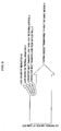
- Non-Patent Documentation 2 as shown in FIG. 40 , a sunlight collecting system (in a beam-down method) is disclosed, in which a light collecting reflector 62 is placed in a high place a little downward from a light collecting point F of light reflected by a plurality of heliostats 61 placed on the ground. Thus, sunlight is reflected downward to the ground by the light collecting reflector 62 to be collected to the heat collector 63 near the ground.
- a heat collector used in the sunlight collecting system an apparatus is disclosed in which molten salt poured in a circular flow path formed in a space between double nested heat collecting containers in truncated cone shapes. Then, the sunlight irradiates an inside of the heat collecting container to indirectly heat the molten salt.
- Non-Patent Documentation 2 there is no discussion about optimizing the shape of the heat collector.
- the molten salt flows slowly inside the circular flow path so as to have a longer response time to control a temperature corresponding to changes in a temperature of the molten salt in an outlet of the heat collecting container when a quantity of solar radiation changes. Therefore, it is difficult to fmely control the temperature by flow control.
- an efficiency of sunlight utilization is further improved.
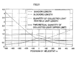
- a radius of the light collecting reflector 62 is several tens meters or more, and installation height is approximately 100m.
- the reflector is subject to a high wind pressure. Therefore, a pulse of the wind displaces the position of the reflector or transforms the reflector itself so as to cause an accuracy of light collection to decrease.
- a structure to support the reflector needs to be firmly constructed to stand against the strong wind during stormy weather, so as to cause a construction cost to increase.
- the heat collector or the light collecting reflector is provided at a light collecting point formed by a plurality of heliostats.
- Non-Patent Document 3 a light collecting system in which a plurality of towers are placed is proposed.
- all heliostats are made to belong to and collect light to a nearest tower. Therefore, when the light collecting system is installed in the northern hemisphere for instance, the number density of the heliostats is large on a south side of the tower causes the light collecting system to be inefficient (, that is, the number of heliostats required to obtain the same quantity of light increases).
- the first object of the invention to provide a solar heat collector which collects and stores thermal energy of sunlight in heat exchange medium with high efficiency and quality.
- a solar heat collector including a heat collecting element whose inner surface constitutes a light receiving surface to receive sunlight, a sunlight inlet which is opened at an end of the heat collecting element, a heat exchange medium inlet through which heat exchange medium is introduced into the heat collecting element, and a heat exchange medium outlet through which the heat exchange medium heated by the sunlight introduced through the sunlight inlet is sent out, the solar heat collector in which the heat collecting element is formed by a helically wound heat exchange medium circulation pipe inside which the heat exchange medium flows, in such a way to have an incurved light receiving surface which narrows and converges towards the sunlight inlet.
- the heat collecting element is formed by a helically wound heat exchange medium circulation pipe inside which the heat exchange medium flows, in such a way to have an incurved light receiving surface which narrows and converges towards the sunlight inlet.
- the heat exchange medium which flows inside the heat exchange medium circulation pipe is heated by the sunlight which is introduced through the sunlight inlet and irradiates the light receiving surface, and sent out through the heat exchange medium outlet. Then, thermal energy stored in the heat exchange medium is used.
- the heat collecting element is formed in such a way to have an incurved light receiving surface which narrows and converges towards the sunlight inlet, it is possible to reduce a quantity of reflected light which disperses from the sunlight inlet to the outside. Therefore, it is possible to improve an efficiency (a ratio of the sunlight which is converted into thermal energy) of the sunlight utilization. Moreover, it is similarly possible to reduce a quantity of thermal radiation, which is generated from a light receiving surface with a high temperature and disperses to the outside. Consequently, it is possible to reduce heat loss caused by the thermal radiation, as well as heat loss accompanied by a flow of the air such as wind.
- a solar heat collector including a heat collecting element which has a light receiving surface on an inner surface to receive sunlight, a sunlight inlet which is opened at an end of the heat collecting element, a heat exchange medium inlet which is provided on a top of the heat collecting element, and a heat exchange medium outlet which is provided at a bottom of the heat collecting element and through which the heat exchange medium heated by the sunlight introduced through the sunlight inlet is sent out, the solar heat collector in which the heat collecting element causes the heat exchange medium to gravitationally flow down as a liquid film along the light receiving surface from the heat exchange medium inlet and sends out the heat exchange medium through the heat exchange medium outlet in such a way that the sunlight directly irradiates and heats the heat exchange medium.
- the heat collecting element causes the heat exchange medium to gravitationally flow down as a liquid film along the light receiving surface from the heat exchange medium inlet and sends out the heat exchange medium through the heat exchange medium outlet.
- sunlight which is introduced from the sunlight inlet to irradiate the light receiving surface directly irradiates and heats the heat exchange medium which gravitationally flows down as a liquid film along the light receiving surface.
- the heat exchange medium is sent out through the heat exchange medium outlet.
- heat is stored in the heat exchange medium to be used.
- the sunlight directly heats the heat exchange medium while the structural materials of the heat collecting element are indirectly heated through the liquid film. Therefore, it is possible to prevent a temperature from becoming so high that heat resistance design can be simple and the heat collecting element can be downsized.
- a solar energy utilization system including the solar heat collector of the first aspect A or B of the present invention.
- thermal energy stored in the heat exchange medium which is sent out from the solar heat collector can be used as a heat source for processes in power generation systems, various kinds of systems of chemical reaction processes, seawater desalination facilities, and so on.
- the solar heat collector according to the first or second aspect of the present invention is used to construct a system highly efficient to use sunlight as thermal energy.
- a sunlight collecting reflector which reflects sunlight collected to a light collecting point by a plurality of first reflectors and makes the reflected sunlight converge on a heat collector, including a reflector group including a plurality of reflector segments, in which each of the reflector segments includes a reflecting surface which makes the sunlight converge on the heat collector.
- the reflector group including a plurality of the reflector segments can make the sunlight which is collected by the first reflector efficiently converge on the heat collector.
- each of the reflector segments can be downsized so that wind resistant design becomes simple.
- reflecting surfaces of each of the reflector segments included in the reflector group are arranged along quadrics of revolution whose confocus is located at the light collecting point of the sunlight and whose curvature radiuses are different.
- each of the reflector segments included in the reflector group are arranged along quadrics of revolution whose confocus is located at the light collecting point of the sunlight and whose curvature radiuses are different, convergence of the light increases. Therefore, it is possible to prevent the light receiving surface from spreading so that the solar energy can be collected to a heat collector which is smaller than conventional one.
- the reflector group includes a number n (n is an integer greater than or equal to 2) of the reflector segments which are arranged along a direction from the light collecting point to the heat collector.
- n is an integer greater than or equal to 2
- the reflector group since in the sunlight collecting reflector, the reflector group includes the number n (n is an integer greater than or equal to 2) of the reflector segments which are arranged along the direction from the light collecting point to the heat collector, and in the reflector group, there is the relationship of R k ⁇ R k +1 between the curvature radius R k of the quadric of revolution along which the reflecting surface of the k-th (k is an integer and 1 ⁇ k ⁇ n-1) nearest reflector segment S k to the light collecting point F1 is placed and the curvature radius R k+1 of the quadric of revolution along which the reflecting surface of the k+1-th nearest reflector segment S k+1 is placed, the sunlight collected to the light collecting point by the plurality of the first reflectors can be reflected by each of the reflector segments so as to converge on the heat collector.
- the reflecting surface of the reflector segment is formed by a portion of the quadric of revolution.
- the sunlight collected to the light collecting point by the plurality of the first reflectors can be reflected by the reflecting surface of each of the reflector segments which is formed by a portion of the quadric of revolution, so as to converge on the heat collector.
- the reflecting surface of the reflector segment is formed by a tangential plane of the quadric of revolution.
- the reflecting surface of the reflector segment is formed by a tangential plane of the quadric of revolution, it is possible to control incident light heat fluxes on the light receiving surface of the heat collector so as to equalize energy with equal heat fluxes.
- the reflecting surface of the reflector segment includes a set of reflector units each of which is formed by a portion or a tangential plane of the quadric of revolution.
- the reflector segment has the reflecting surface including the set of the reflector units formed by the portion or the tangential plane of the quadric of revolution, the sunlight collected to the light collecting point by the plurality of the first reflectors can be reflected by the reflecting surface including the set of the reflector units, so as to converge on the heat collector, and a form of the reflecting surface in each of the reflector segments can be adjusted by the reflector unit.
- the quadric of revolution is at least one kind of curved surface selected from a hyperboloid of revolution and an ellipsoid of revolution.
- the quadric of revolution is at least a kind of curved surface selected from the hyperboloid of revolution and the ellipsoid of revolution, the sunlight collected to the light collecting point by the plurality of the first reflectors can be reflected by the reflecting surface of each of the reflector segments, so as to converge on the heat collector.
- a plurality of the reflector segments are arranged without overlapping between light paths of the sunlight collected to the light collecting point by the plurality of the first reflectors and the reflected sunlight.
- the plurality of the reflector segments are arranged without overlapping between light paths of the sunlight collected to the light collecting point by the plurality of the first reflectors and the reflected sunlight, the sunlight collected to the light collecting point by the plurality of the first reflectors can be reflected by the reflecting surface of each of the reflector segments, so as to efficiently converge on the heat collector.
- the reflecting surface of the reflector segment is preferably formed in a ring shape around a central axis which is a center line connecting the light collecting point of the sunlight with a center of a light collecting surface of the heat collector, along the quadric of revolution.
- the ring may include a circular ring and a circular arc, and the shape is optimally determined depending on how the plurality of the first reflectors are arranged.
- the reflecting surface of the reflector segment is formed in the ring around the central axis which is the center line connecting the light collecting point of the sunlight with the center of the light collecting surface of the heat collector, along the quadric of revolution, the sunlight collected to the light collecting point by the plurality of the first reflectors can be reflected by the reflecting surface of each of the reflector segments, so as to converge on the heat collector.
- a solar energy utilization system including the sunlight collecting reflector.
- thermal energy of sunlight which is made efficiently converge on a heat collector by the sunlight collecting reflector can be used as a thermal energy source for power generation, synthetic fuel manufacture, various kinds of chemical processes, or seawater desalination facilities.
- the heat collector is preferably a solar heat collector including a heat collecting element whose inner surface constitutes a light receiving surface to receive sunlight, a sunlight inlet which is opened at an end of the heat collecting element, a heat exchange medium inlet through which heat exchange medium is introduced into the heat collecting element, and a heat exchange medium outlet through which the heat exchange medium heated by the sunlight is sent out, the solar heat collector in which the heat collecting element is formed by a helically wound heat exchange medium circulation pipe inside which the heat exchange medium flows, in such a way to have an incurved light receiving surface which narrows and converges towards the sunlight inlet.
- the sunlight collecting reflector can make the sunlight collected by the first reflector efficiently converge on the heat collector.
- heat loss caused by radiation, as well as heat loss caused by a flow of the air such as wind is reduced so that thermal energy of converging sunlight stored in the heat exchange medium can be efficiently used.
- the heat collector is preferably a solar heat collector including a heat collecting element whose inner surface constitutes a light receiving surface to receive sunlight, a sunlight inlet which is opened at an end of the heat collecting element, a heat exchange medium inlet which is provided on a top of the heat collecting element, and a heat exchange medium outlet which is provided at a bottom of the heat collecting element and through which the heat exchange medium heated by the sunlight introduced through the sunlight inlet is sent out, the solar heat collector in which the heat collecting element causes the heat exchange medium to gravitationally flow down as a liquid film along the light receiving surface from the heat exchange medium inlet and sends out the heat exchange medium through the heat exchange medium outlet, in such a way that the sunlight directly irradiates and heats the heat exchange medium.
- the sunlight collecting reflector can make the sunlight collected by the first reflector efficiently converge on the heat collector.
- thermal energy of converging sunlight is stored in the heat exchange medium which gravitationally flows down as a liquid film, so as to be efficiently used.
- the sunlight directly heats the heat exchange medium. Therefore, it is possible to prevent a temperature from increasing to simplify heat resistance design and downsize the heat collecting element.
- a sunlight collecting system including a plurality of heliostat groups in each of which a plurality of heliostats included in the heliostat group forms a light collecting point of sunlight, the sunlight collecting system in which among spaces adjacent to a plurality of heliostats An (n is an integer greater than or equal to 2) included in a heliostat group A which collects sunlight to one light collecting point Fa, a plurality of heliostats Bm (m is an integer greater than or equal to 2) included in a heliostat group B which collects sunlight to another light collecting point Fb are arranged in places where the sunlight irradiates the ground, and in which the heliostats An and the heliostats Bm are arranged in such a way that a light path of light reflected by each of the heliostats An and the heliostats Bm is formed in a direction to the light collecting point of the heliostat
- the plurality of heliostats Bm (m is an integer greater than or equal to 2) included in the heliostat group B which collects sunlight to the light collecting point Fb are arranged in places which are irradiated by unused sunlight due to blocking between the plurality of heliostats An (n is an integer greater than or equal to 2) included in the heliostat group A which collects sunlight to the light collecting point Fa. Then, the heliostats An and the heliostats Bm are arranged in such a way that the light path of the light reflected by each of the heliostats An and the heliostats Bm is formed in a direction to the light collecting point of the heliostat group in which the heliostat is included.
- the heliostat An and the heliostat Bm preferably have identical or different forms.
- a plurality of the heliostats are arranged to form a heliostat group to form one light collecting point, at first. Then, another plurality of heliostats are arranged in places which are irradiated by sunlight between the arranged heliostats to form a heliostat group facing to a direction different from the arranged heliostats.
- another light collecting point is formed so that a light collection efficiency can be improved.
- there is an advantage that productions, installation positions, and so on of the heliostats are simple.
- the heliostat An and the heliostat Bm have different forms, a plurality of the heliostats which have either one of the forms are arranged to form one light collecting point. Then, heliostats which have another form are arranged in places irradiated by the sunlight between the arranged heliostats. Thus, another light collecting point is formed so that a light collection efficiency can be improved.
- the heliostats which are included in either one of the heliostat groups have a form appropriate to the places which are irradiated by the sunlight between the arranged heliostats.
- the form corresponds to shapes, forms, and so on of the heliostats which form the other heliostat group.
- the heliostat group A and the heliostat group B are preferably arranged in such a way that the another light collecting point Fb is formed on a north side of the one light collecting point Fa in a northern hemisphere and on a south side of the one light collecting point Fa in a southern hemisphere.
- the north or the south is described in accordance with cases in the northern hemisphere unless otherwise specified.
- the north and the south are to be swapped.
- the south should be replaced with the north
- the north should be replaced with the south.
- the heliostat groups A and the heliostat groups B are arranged in such a way that a required number of light collecting points are formed with almost equal intervals so that the another light collecting points Fb are formed on the north side of the one light collecting points Fa in the northern hemisphere and on the south side of the one collection point Fa in the southern hemisphere.
- a required quantity of sunlight can be efficiently collected even in a long and slender region regardless of an area of a region where the heliostats are arranged.
- the heliostat group A preferably includes a plurality of first heliostats.
- the heliostat group B preferably includes a plurality of second heliostats.
- the light collecting point Fb of the heliostat group B is preferably formed on the north side or the south side of the light collecting point Fa formed by the heliostat group A depending on whether the light collecting system is located in a region in the northern hemisphere or the southern hemisphere.
- the first heliostats are preferably arranged in such ways that the reflecting surfaces are directed to face the sun and the light collecting point Fa.
- the second heliostats are preferably arranged in places which are irradiated by the sunlight between the plurality of the first heliostats An (n is an integer greater than or equal to 2) included in the heliostat group A and nearer to the ground than the first heliostats in such a way that the reflecting surfaces are directed to face the sun and the light collecting point Fb.
- the plurality of the second heliostats included in the heliostat group B which collects the sunlight to the other light collecting point Fb are arranged in the places which are irradiated by sunlight which is unused due to the blocking between the plurality of the first heliostats included in the heliostat group A.
- the first heliostats are arranged in such ways that the reflecting surfaces are directed to face the sun and the light collecting point Fa.
- the second heliostats are arranged in such ways that the reflecting surfaces are directed to face the sun and the light collecting point Fb.
- the second heliostats are arranged in the places which are irradiated by the sunlight between the plurality of the first heliostats An (n is an integer greater than or equal to 2) included in the heliostat group A and nearer to the ground than the first heliostats. Therefore, light paths of light reflected by the first heliostats and the second heliostats are directed to the light collecting points Fa or Fb of the heliostat group to which each of the heliostats belongs. As a result, there are no more regions where the ground is irradiated by sunlight which is unused due to the blocking. Consequently, it is possible to collect almost all of the sunlight which irradiates the region where the heliostats are arranged to a plurality of light collecting points to collect energy of the collected sunlight.
- the second heliostat can change a position and move the reflecting surface of the second heliostat itself to follow the sun in accordance with a time during a daytime and a season, in such a way to receive the maximum sunlight on the reflecting surface.
- the second heliostat can change a position and move the reflecting surface of the second heliostat itself to follow the sun in accordance with a time during a daytime and a season, in such a way to receive the maximum sunlight, the second heliostat can move to a position to avoid shadows which are formed by the first heliostats and hourly change with changes in elevation of the sun during a day and seasonally. As a result, the light collection efficiency can be improved.
- the heliostat groups A and the heliostat groups B are alternately arranged in a north-south direction.
- a heliostat group B h1 (h1 is an integer greater than or equal to 1) and a next heliostat group A k1 (k1 is an integer greater than or equal to 2) preferably form one light collecting point.
- the heliostat groups A and the heliostat groups B are alternately arranged in the north-south direction and since the heliostat group B h1 (h1 is an integer greater than or equal to 1) and the next heliostat group A k1 (k1 is an integer greater than or equal to 2) form one light collecting point, a required number of light collecting points can be formed in series in the north-south direction with almost equal intervals in such a way that the other light collecting point Fb is formed on the north side of the one light collecting point Fa. Therefore, a required quantity of sunlight can be efficiently collected even in a long and slender region regardless of an area of the region where the heliostats are arranged.
- the sunlight collecting system preferably includes a unit including three heliostat groups.
- the heliostat groups are preferably arranged in such a way that three light collecting points respectively formed by the heliostat groups included in the unit are located at vertices of a triangle whose base is directed in an east-west direction.
- the sunlight collecting system includes the unit including the three heliostat groups and the heliostat groups are arranged in such a way that the three light collecting points respectively formed by the heliostat groups included in the unit are located on the vertices of the triangle whose base is directed in the east-west direction
- the first heliostats are arranged in such a way to select a light collecting point to maximize a quantity of collected light.
- the second heliostats are arranged in the regions where the blocking occurs. Accordingly, light can be collected to the light collecting point which maximizes the quantity of the collected light on the north side of the heliostats.
- the second heliostats can form an optimal light collecting point at any time in accordance with changes during a day and seasonal changes in an irradiation angle of the sunlight. Consequently, the quantity of the collected light in a year can be maximized comparing with the light collecting system in which heliostats are fixed.
- the triangle is preferably an isosceles triangle whose base is directed in the east-west direction and whose apex is located on a north side of the base in the northern hemisphere or on a south side of the base in the southern hemisphere.
- the triangle is the isosceles triangle whose base is directed in the east-west direction, the light collection efficiency can be further improved.
- the units are preferably arranged in a triangular lattice in the east-west direction and the north-south direction.
- the units are arranged in a triangular lattice in the east-west direction and a north-south direction, a light collection efficiency can be improved in any shape of field. Moreover, when the towers are arranged to be staggered every row, influence of the shadows can be reduced.
- a solar energy utilization system in which a heat collector is placed at each of the light collecting points respectively formed by a plurality of heliostat groups in the sunlight collecting system to collect energy of the collected sunlight.
- the heat collector is placed at each of the light collecting points respectively formed by the plurality of the heliostat groups in the sunlight collecting system to collect energy of the collected sunlight, the sunlight which irradiates the region where the heliostats are arranged is collected with a high field efficiency so that thermal energy of the collected sunlight can be efficiently used.
- a solar energy utilization system in which a reflector which has a reflecting surface formed along a quadric of revolution is placed at each of the light collecting points respectively formed by the plurality ofheliostat groups in the sunlight collecting system to collect the sunlight and the thermal energy of the collected sunlight to the heat collector which is placed under the reflector.
- the reflector which has a reflecting surface formed along the quadric of revolution is placed at each of the light collecting points respectively formed by the plurality of heliostat groups in the sunlight collecting system to collect the sunlight and the thermal energy of the collected sunlight to the heat collector which is placed under the reflector, the sunlight which irradiates the region where the heliostats are arranged is collected with a high field efficiency so that thermal energy of the collected sunlight can be efficiently used.
- a solar energy utilization system in which the thermal energy of the sunlight collected by the sunlight collecting system is used for power generation or industrial processes.
- the sunlight which irradiates the region where the heliostats are arranged is collected with a high field efficiency so that thermal energy of the collected sunlight can be efficiently used.
- the heat collector is preferably a solar heat collector including a heat collecting element whose inner surface constitutes a light receiving surface to receive sunlight, a sunlight inlet which is opened at an end of the heat collecting element, a heat exchange medium inlet through which heat exchange medium is introduced into the heat collecting element, and a heat exchange medium outlet through which the heat exchange medium heated by the sunlight is sent out, the solar heat collector in which the heat collecting element is formed by a helically wound heat exchange medium circulation pipe inside which the heat exchange medium flows, in such a way to have an incurved light receiving surface which narrows and converges towards the sunlight inlet.
- the solar heat collector according to the first aspect A of the present invention is used as a heat collector, so as to make sunlight collected by a first reflector efficiently converge on the heat collector.
- energy of the converging sunlight can be highly efficiently stored in the heat exchange medium so that the stored thermal energy can be used.
- the heat collector is preferably a solar heat collector including a heat collecting element whose inner surface constitutes a light receiving surface to receive sunlight, a sunlight inlet which is opened at an end of the heat collecting element, a heat exchange medium inlet which is provided on a top of the heat collecting element, and a heat exchange medium outlet which is provided at a bottom of the heat collecting element and through which the heat exchange medium heated by the sunlight introduced through the sunlight inlet is sent out, the solar heat collector in which the heat collecting element causes the heat exchange medium to gravitationally flow down as a liquid film along the light receiving surface from the heat exchange medium inlet and sends out the heat exchange medium through the heat exchange medium outlet.
- the plurality of the heliostat groups collect the sunlight with a high field efficiency and the heat collector placed at each of the light collecting points stores the energy of the collected sunlight in the heat exchange medium which gravitationally flows down as a liquid film and efficiently collects the energy so that the thermal energy of the sunlight can be efficiently used.
- the reflector is preferably a sunlight collecting reflector which reflects sunlight collected to a light collecting point by a plurality of first reflectors and makes the reflected sunlight converge on the heat collector, including a reflector group including a plurality of reflector segments, in which each of the reflector segments has a reflecting surface which makes the sunlight converge on the heat collector.
- the plurality of the heliostat groups collect the sunlight with a high field efficiency and the sunlight collecting reflector makes the energy of the collected sunlight efficiently converge on the heat collector so that the thermal energy of the sunlight can be efficiently used.
- the heat collector is preferably a solar heat collector including a heat collecting element whose inner surface constitutes a light receiving surface to receive sunlight, a sunlight inlet which is opened at an end of the heat collecting element, a heat exchange medium inlet through which heat exchange medium is introduced into the heat collecting element, and a heat exchange medium outlet through which the heat exchange medium heated by the sunlight is sent out, the solar heat collector in which the heat collecting element is formed by a helically wound heat exchange medium circulation pipe inside which the heat exchange medium flows, in such a way to have an incurved light receiving surface which narrows and converges towards the sunlight inlet, and the reflector is preferably a sunlight collecting reflector which reflects sunlight collected to a light collecting point by a plurality of first reflectors and makes the reflected sunlight converge on the heat collector, including a reflector group including a plurality of reflector segments, in which each of the reflector segments has a reflecting surface which makes the sunlight converge on the heat collector.
- the sunlight collecting reflector can efficiently collect the sunlight reflected to the light collecting point by the plurality of the first reflectors.
- the collected sunlight can be made converge on the solar heat collector according to the first aspect A of the present invention. Then, energy of the converging sunlight can be highly efficiently stored in the heat exchange medium, and the stored thermal energy can be used.
- the heat collector is preferably a solar heat collector including a heat collecting element whose inner surface constitutes a light receiving surface to receive sunlight, a sunlight inlet which is opened at an end of the heat collecting element, a heat exchange medium inlet which is provided on a top of the heat collecting element, and a heat exchange medium outlet which is provided at a bottom of the heat collecting element and through which the heat exchange medium heated by the sunlight introduced through the sunlight inlet is sent out, the solar heat collector in which the heat collecting element causes the heat exchange medium to gravitationally flow down as a liquid film along the light receiving surface from the heat exchange medium inlet and sends out the heat exchange medium through the heat exchange medium outlet, and in which the reflector is preferably a sunlight collecting reflector which reflects sunlight collected to a light collecting point by a plurality of first reflectors and makes the reflected sunlight converge on the heat collector, including a reflector group including a plurality of reflector segments, in which each of the reflector segments has a reflecting surface which makes the sunlight
- the sunlight collecting reflector can efficiently collect the sunlight reflected to the light collecting point by the plurality of the first reflectors.
- the collected sunlight can be made converge on the solar heat collector according to the first aspect B of the present invention. Then, energy of the converging sunlight can be stored in the heat exchange medium which gravitationally flows down as a liquid film so that the stored thermal energy can be efficiently used.
- FIG. 1 is a schematic diagram showing an example of a solar heat collector according to a first embodiment of the invention.
- the solar heat collector 1 whose outline is shown in FIG. 1 includes a heat collecting element 3, a sunlight inlet 4 which is opened at an end of the heat collecting element 3, a heat exchange medium inlet 5 through which heat exchange medium is introduced into the heat collecting element 3, and a heat exchange medium outlet 6 as shown in FIG. 2(a) .
- the heat collecting element 3 is formed by a helically wound circulating heat exchange medium circulation pipe 7 inside which the heat exchange medium flows.
- a light receiving surface 2 is constituted of an outer peripheral side of the heat exchange medium circulation pipe 7 which is exposed inside the heat collecting element 3. Then, the light receiving surface 2 is incurved to narrow towards the sunlight inlet 4 which is opened at the end of the heat collecting element 3.
- the incurved shape of the light receiving surface 2 is optimally formed by the wound heat exchange medium circulation pipe 7 in accordance with heat flux distribution of collected sunlight SB and the like as described later.
- the shape is optimally formed in a cavity shape having a cross section which is narrow in the upper portion (on a side of the sunlight inlet 4) and wide in the lower portion (on a side of the heat exchange medium inlet 5) as a whole as shown in a schematic cross section of FIG. 2(a) .
- a pipe whose cross-sectional shape is any of a circle, a rectangular, and so on may be used as a heat exchange medium circulation pipe 7 included in the heat collecting element 3.
- a pipe with a circular cross-sectional shape is advantageous since a smaller number of parts are welded in producing a flow path.
- Austenitic stainless steel is advantageous in view of corrosion resistance, heat resistance, a price, and so on as a material of the heat exchange medium circulation pipe 7, in a case where mixed molten salt of NaNO 3 and KNO 3 or mixed molten salt of NaNO 3 , KNO 3 , and NaNO 2 is used as the heat exchange medium.
- thickness of the pipe is determined as needed in accordance with a pressure of the molten salt, required high-temperature strength, and so on.
- the light receiving surface 2 of the heat exchange medium circulation pipe 7 is preferably processed for light absorbance and heat resistance.
- paint excellent for the light absorbance and the heat resistance is painted on the light receiving surface 2, or a chemical surface treatment excellent for the light absorbance and the heat resistance is applied.
- "light absorbance” means that absorption coefficient of light elements with a wavelength bandwidth of 0.2-2.5 ⁇ m among sunlight elements is 80% or more.
- Pyromark Paint produced by B.J.Wolfe Enterprise, and the like may be used as the paint excellent for the light absorbance and the heat resistance.
- an insulating portion (not shown) is preferably provided outside the heat collecting element 3. Accordingly, heat radiation from the peripheral wall of the heat collecting element 3 to the outside is blocked so as to efficiently prevent loss of the thermal energy of the heat exchange medium.
- the insulating portion which is made of ceramic fiber insulation material whose principal components are alumina, silica, and so on, may be formed outside the heat collecting element 3.
- the sunlight inlet 4 is opened at one end of the heat collecting element 3 so that the collected sunlight is introduced through the sunlight inlet 4. Then, the introduced sunlight SB irradiates the light receiving surface 2 so as to indirectly heat the heat exchange medium which circulates inside the heat exchange medium circulation pipe 7 which forms the light receiving surface 2.
- the sunlight inlet 4 may be opened also at a lower end of the heat collecting element 3.
- the heat exchange medium inlet 5 and the heat exchange medium outlet 6 may be also respectively provided at the upper end and the lower end of the heat collecting element 3.
- the sunlight inlet 4, the heat exchange medium inlet 5, and the heat exchange medium outlet 6 are not necessarily arranged in this way, but may be arranged in various ways. For instance, when the sunlight enters from the upper side, the opening is preferably provided in the upper portion. And, when the sunlight enters from the lower side, the opening is preferably provided in the lower portion.
- the heat exchange medium inlet 5 in the bottom center of the heat collecting element 3 is connected with the heat exchange medium circulation pipe 7 which forms the heat collecting element 3.
- the heat exchange medium which is pushed out by a sender such as a pump (not shown) is introduced into the heat exchange medium circulation pipe 7.
- a flow quantity controller such as a valve may be provided in the heat exchange medium inlet 5 to control flow rate of the heat exchange medium which circulates inside the heat exchange medium circulation pipe 7.
- the heat exchange medium outlet 6 on the top of the heat collecting element 3 is connected with the heat exchange medium circulation pipe 7 which forms the heat collecting element 3.
- the heat exchange medium which circulates inside the heat exchange medium circulation pipe 7 and is heated by the sunlight, is sent out through the heat exchange medium outlet 6.
- the heat exchange medium inlet 5 and the heat exchange medium outlet 6 are not necessarily arranged as shown in FIGS. 1 and 2(a) , but may be arranged respectively on the top and in the bottom center of the heat collecting element 3. Particularly, this arrangement is advantageous when first incident light of the sunlight converges on the upper portion of the heat collecting element 3.
- Any heat exchange medium whose heat resistant temperature is greater than or equal to 500°C may be used with no special limitation.
- mixed molten salt of NaNO 3 and KNO 3 or mixed molten salt of NaNO 3 , KNO 3 , and NaNO 2 may be used.
- the molten salt or the mixed molten salt is used to provide temperature and energy which promote chemical reaction of fuel conversion (for instance, reforming reaction of natural gas), thermal energy for steam turbine power generation, or a heat source for a seawater desalination facility.
- Shape of the heat collecting element 3 in the solar heat collector 1 is optimized in consideration of a temperature of the light receiving surface 2 which is irradiated by the sunlight, heat transfer from the light receiving surface 2 to the heat exchange medium, distribution of heat fluxes of the introduced sunlight (thermal energy per unit area of the light receiving surface), and so on.
- the shape of the heat collecting element 3 includes an opening diameter and an opening shape of the sunlight inlet 4, and the incurved shape of the light receiving surface which is formed by the wound heat exchange medium circulation pipe 7.
- heat balance in heat collecting element 3 is defined as shown in FIGS. 1 and 3 . More specifically, incident energy, that is, thermal energy of the sunlight SB introduced through the sunlight inlet 4 is assumed to be 100.
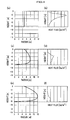
- FIG. 4(b) shows heat flux distribution in which heat fluxes concentrate on the upper portion in a case of the heat collecting element 3 with a quadrangle cross section shown FIG. 4(a) .
- FIG. 4(d) shows heat flux distribution which is almost averaged except a peak in the center of the heat collecting element 3 in the case of the heat collecting element 3 with a cross-sectional shape shown in FIG. 4C .
- FIG. 4(f) shows distribution of heat fluxes which are averaged in the height direction of the heat collecting element 3 in a case of the heat collecting element 3 with a cross-sectional shape shown in FIG. 4(e) .
- a shape of the heat collecting element 3 shown in FIG. 5 is effective to optimize the heat flux distribution on the light receiving surface 2 and to improve an efficiency of sunlight utilization in the solar heat collector 1, that is, A/100.
- the shape is a cavity shape with a cross section which is narrow in the upper portion and wide in the lower portion as a whole, having a relationship expressed by the following formulas (1) and (2).
- an opening diameter of the sunlight inlet 4 is denoted by Da
- height of the heat collecting element 3 is denoted by Ho
- height of the most expanded portion M measured from the opposite side of the opening of the heat collecting element 3 is denoted by Hm
- the diameter of the most expanded portion M is denoted by Dmax. 1 ⁇ Dmax / Da ⁇ 3 0 ⁇ Hm / Ho ⁇ 0.8
- internal diameter of the heat exchange medium circulation pipe 7 (the pipe) which forms the light receiving surface 2 is determined by an upper limit temperature of the heat exchange medium for use and an upper limit temperature of an inner surface of the heat exchange medium circulation pipe 7 which contacts with the heat exchange medium.
- an upper limit of pressure loss in the heat exchange medium circulation pipe 7 is determined by restriction of the maximum discharge pressure of the pump which sends the heat exchange medium. Therefore, the whole shape of the heat collecting element 3 and the internal diameter of the heat exchange medium circulation pipe 7 can be determined to meet these two restrictive conditions.
- a surface temperature on a heat exchange medium side of the light receiving surface 2 which is irradiated and heated by the sunlight SB is assumed to be 600°C, and a magnitude of the heat fluxes to the inside from the outside of the heat exchange medium circulation pipe 7 is assumed to be 300kW/m 2 .
- a temperature of the heat exchange medium which circulates inside the heat exchange medium circulation pipe (the pipe) 7 made of SUS316 stainless steel with a thickness of 5mm is approximately 550°C. Therefore, a thickness, a material, an internal diameter, and so on of the heat exchange medium circulation pipe 7 can be determined as needed in consideration of such a temperature distribution.
- the heat exchange medium is introduced through the heat exchange medium inlet 5 to circulate inside the heat exchange medium circulation pipe 7.
- the heat exchange medium is heated through the light receiving surface 2 irradiated by the sunlight which is introduced through the sunlight inlet 4.
- the heated heat exchange medium is sent out through the heat exchange medium outlet 6 and supplied as a heat source for various systems and processes such as a power generation system and a chemical reaction process.
- a flow rate, a flow velocity, and so on of the heat exchange medium are controlled so as to keep a temperature of the mixed molten salt which circulates inside the heat exchange medium circulation pipe 7, within a range between two temperatures of a melting point (220°C) of the mixed molten salt and the upper limit temperature (600°C) of the mixed molten salt for use.
- the solar heat collector 1 In the solar heat collector 1, a part of the sunlight which irradiates the light receiving surface 2 is reflected. However, most of the reflected light re-irradiates the other part of the light receiving surface in the solar heat collector 1 so that the reflected light which disperses outside through the sunlight inlet 4 decreases. Accordingly, the solar heat collector 1 is effective to improve the efficiency (the ratio of the irradiated sunlight which is converted into heat) of the irradiated sunlight utilization. Moreover, it is similarly possible to reduce a quantity of thermal radiation, which is generated from a light receiving surface with a high temperature and disperses to the outside, so as to reduce heat loss caused by the thermal radiation. In addition, as shown in FIG. 1 , the heat collecting element is formed in the cavity-shape with the narrow upper cross section so as to reduce the heat loss caused by the heat convection.
- both of a diameter and a height are approximately 10-20m in a case where a thermal power is 100MW.
- a structure in which a pipe is helically bent to form a furnace is more advantageous in structural strength and can be easily produced since thermal stress can be smaller, comparing with a structure in which metal plates are combined to form a flow path.
- the solar heat collector 1 may include a mechanism which insulates and blocks the sunlight SB in the sunlight inlet 5. In an emergency case such as where the heat collecting element 3 has lost cooling ability, the mechanism protects the heat collecting element 3.
- the solar heat collector 1 of the first embodiment described above is formed by a so-called one thread roll which is formed by one wound heat exchange medium circulation pipe 7.
- the solar heat collector 1 of the invention may be formed by a plurality of wound heat exchange medium circulation pipes 7. For instance, as shown in FIGS. 7(a) and 7(b) , eight heat exchange medium circulation pipes 7a, 7b, 7c, 7d, 7e, 7f, 7g, and 7h may be wound to form the solar heat collector 1.
- the heat exchange medium inlet 5 and the heat exchange medium outlet 6 may include headers with branch inlet and outlet pipes which is branched and connected to the eight heat exchange medium circulation pipes 7a, 7b, 7c, 7d, 7e, 7f, 7g, and 7h.
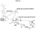
- FIG. 8 is a schematic diagram showing an example of a solar energy utilization system according to a second embodiment, which uses the solar heat collector 1 according to the first embodiment of the invention.
- the solar energy utilization system shown in FIG. 8 includes a first light collecting system FC, a second light collecting system SC, a third light collecting system CPC, a solar heat collector 1, a high-temperature heat exchange medium tank 81, a heat exchanger 82, a low-temperature heat exchange medium tank 83, and a heat exchange medium purification system 84.
- the solar heat collector 1, the high-temperature heat exchange medium tank 81, the heat exchanger 82, the low-temperature heat exchange medium tank 83, and the heat exchange medium purification system 84 are connected with each other by flow paths through which heat exchange medium circulates.
- valves, and so on are arranged in places.
- a solar heat collector 1 similar to the solar heat collector according to the first embodiment is used.
- the high-temperature heat exchange medium tank 81, the heat exchanger 82, the low-temperature heat exchange medium tank 83, and the heat exchange medium purification system 84 are not limited specially and can be selected in accordance with heat exchange medium to be used, capacity, purity requirement of the heat exchange medium, and so on, as needed.
- the sunlight SB from the sun S is collected by the first light collecting system FC and the second light collecting system SC which include the reflectors, and so on.
- the collected sunlight SB is further collected by the third light collecting system CPC above the solar heat collector 1 and introduced through the sunlight inlet 4 of the solar heat collector 1.
- the introduced sunlight SB irradiates the light receiving surface 2 of the solar heat collector 1.
- the heat exchange medium which is introduced through the heat exchange medium inlet 5 and circulates inside the heat exchange medium circulation pipe 7, is heated through the light receiving surface 2.
- the heated heat exchange medium which stores thermal energy is sent out through the heat exchange medium outlet 6 (refer to FIGS. 1 and 2 ).
- the heat exchange medium sent out through the heat exchange medium outlet 6 is sent to the high-temperature heat exchange medium tank 81 through the flow path. Then, the heat exchange medium sent to the high-temperature heat exchange medium tank 81 is supplied to the heat exchanger 82 and supplies the thermal energy to a heat utilization facility which is connected with the heat exchanger 82.
- the heat utilization facility performs steam turbine power generation, pyrolysis of hydrocarbon, production of liquid fuel from natural gas and coals, or the like.
- a part of the thermal energy of the heat exchange medium is exchanged by the heat exchanger 82 so that a temperature of the heat exchange medium lowers. Then, the heat exchange medium is sent to and temporarily stored in the low-temperature heat exchange medium tank 83. And, the heat exchange medium with a low temperature which is temporarily stored in the low-temperature heat exchange medium tank 83 is purified by the heat exchange medium purification system 84 and supplied to the heat exchange medium inlet 5 of the solar heat collector 1, again.
- the heat exchange medium purification system 84 prevents the circulating heat exchange medium and the piping material from corroding and degrading to block the heat exchange medium circulation pipe 7, and the like, or prevents thermal capacity of the heat exchange medium from decreasing to decrease an efficiency of sunlight energy utilization.
- the heat exchange medium purification system 84 purifies the heat exchange medium to remove corrosion products from the heat exchange medium so that the solar heat collector 91 can operate stably for a long-term. Moreover, when the purification of the heat exchange medium is not necessary, the heat exchange medium can be supplied to the solar heat collector 1 not through the heat exchange medium purification system 84 but through a by-pass in the heat exchange medium purification system 84 without being purified.
- the high-temperature heat exchange medium tank 81 stores the heat exchange medium and supplies the heat exchange medium to the heat exchanger 82 in accordance with required thermal energy in the heat utilization facility. For instance, in a case where the heat utilization facility is a power plant, it is possible to control supplying the heat exchange medium in accordance with changes in a quantity of power to be generated.
- a plant can continuously operate with a constant output power for 24 hours.
- FIG. 9(a) is a schematic cross section showing a solar heat collector 91 according to a third embodiment of the invention.
- the solar heat collector 91 shown in FIG. 9A includes a heat collecting element 93 whose inner surface constitutes a light receiving surface 92 where heat exchange medium gravitationally flows down as a liquid film, a sunlight inlet 94 which is opened on an upper end of the heat collecting element 93, a heat exchange medium inlet 95 through which the heat exchange medium is introduced into the heat collecting element 93, and a heat exchange medium outlet 96.
- the light receiving surface 92 which receives sunlight SB on the inner surface and on which the heat exchange medium gravitationally flows down as a liquid film.
- the light receiving surface 92 is incurved and narrows and converges towards the sunlight inlet 94 which is opened on the upper end of the heat collecting element 93.
- the incurved shape of the light receiving surface 92 is optimized in accordance with heat flux distribution of collected sunlight SB, a viscosity, a flow rate, a thermal conductivity, a liquid film thickness, and so on of the heat exchange medium which gravitationally flows down as a liquid film along the light receiving surface 92.
- a concrete example is a substantial barrel-shape which, as a whole, narrows in an upper portion (on a side of the sunlight inlet 94), widens midway, and has a focus at an end.
- a shape of the solar heat collector of the third embodiment is not limited to a shape with a cross-sectional shape shown in FIG. 9(a) .
- the receiving surface 92 may be formed in a substantial trumpet-shape which tapers from the sunlight inlet 94 opened on the upper end of the heat collecting element 93 towards the heat exchange medium outlet 96.
- the heat collecting element 93 formed by a hyperboloid of revolution which has a focus near an end is also a candidate.
- the heat collecting element 3 may be formed in a cylindrical shape.
- the heat collecting element 93 with the cross-section of the trumpet-shape is advantageous since a small surface area of the heat exchange medium in a region (a lower portion of the heat collecting element 3) where a temperature of the heat exchange medium is high on the light receiving surface 92 can reduce loss caused by thermal radiation on the light receiving surface 92.
- flow guidelines 98 shown in FIG. 10C are preferably protruded on the light receiving surfaces.
- the flow guidelines 98 prevent flows on the light receiving surface 92 from deviating to keep liquid film gravity flow of the heat exchange medium in a good state.
- the flow guidelines are effective to improve structural strength of the heat collecting element 3.
- the light receiving surface 92 of the heat collecting element 93 is preferably processed for light absorbance and heat resistance.
- paint excellent for the light absorbance and the heat resistance is painted on the light receiving surface 2, or a chemical surface treatment excellent for the light absorbance and the heat resistance is applied.
- the paint or the chemical surface treatment excellent for the light absorbance and the heat resistance are similar to those in the first embodiment, and not discussed, here.
- an insulating portion (not shown) is also preferably provided outside the heat collecting element 93, similar to that in the first embodiment, and not discussed, here.
- the sunlight inlet 94 is opened on an upper end of the heat collecting element 93.
- the collected sunlight is introduced through the sunlight inlet 94.
- the introduced sunlight SB irradiates the light receiving surface 2 to directly heat the heat exchange medium which gravitationally flows down as a liquid film along the light receiving surface 2.
- the sunlight inlet 94 may be opened on a lower end of the heat collecting element 93.
- the heat exchange medium inlet 95 is provided on the top of the heat collecting element 93.
- the heat exchange medium inlet 95 includes a distributor which spurts the heat exchange medium pushed out by a sender such as a pump (not shown), along the light receiving surface 92 which is an inner surface of the heat collecting element 93.
- the heat exchange medium spurted from the heat exchange medium inlet 95 forms a liquid film and gravitationally flows down along the light receiving surface.
- a flow quantity controller such as a valve may be provided in the heat exchange medium inlet 95 to control flow rate of the heat exchange medium which gravitationally flows down as a liquid film along the light receiving surface 92.
- the heat exchange medium outlet 96 is provided at the bottom of the heat collecting element 3.
- the heat exchange medium which gravitationally flows down as a liquid film along the light receiving surface 92 and is heated by the sunlight, is sent out through the heat exchange medium outlet 96.
- any heat exchange medium which is viscous enough to gravitationally flow down as a liquid film along the light receiving surface 92 may be used with no special limitation.
- mixed molten salt of NaNO 3 and KNO 3 or mixed molten salt of NaNO 3 , KNO 3 , and NaNO 2 may be used.
- the molten salt or the mixed molten salt can be used to provide temperature and energy which promote chemical reaction of fuel conversion.
- the heat exchange medium used in the solar heat collector 91 of the third embodiment needs to form a liquid film. Therefore, the heat exchange medium preferably has good wettability with a structure (particularly, the light receiving surface 92 of the heat collecting element 93).
- the light receiving surface 92 may be processed into a shape or may have a structure which has good affinity with the heat exchange medium.
- a thickness of a liquid film of the heat exchange medium which gravitationally flows down as a liquid film along the light receiving surface 92 is preferably approximately 1-7mm so as to secure an appropriate flow rate and prevent the liquid film from separating from the light receiving surface 92.
- the heat exchange medium preferably includes heat absorber to improve an absorption coefficient of the thermal energy from the sunlight SB.
- the heat absorber includes a small quantity of colored metal salt such as cobalt nitrate and nickel nitrate.
- the heat absorber includes a small quantity of colored metal salt such as cobalt nitrate and nickel nitrate.
- mixture of Fe(NO 3 ) 3 9H 2 O and CoCl 2 6H 2 O by weight ratio of 1:1 is added to mixed molten salt of KNO 3 and NaNO 3 by 5% to turn the mixed molten salt black.
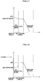
- FIG. 11 and 12 show results of simulating distribution of temperatures inside and outside the heat collecting element 93 in a case of using as the heat exchange medium the turned black mixed molten salt of KNO 3 and NaNO 2 added by these metal salts and in a case of using transparent heat exchange medium consisting of the mixed molten salt of KNO 3 and NaNO 2 respectively.
- the heat exchange medium which gravitationally flows down as a liquid film along a surface of the light receiving surface 92 of the heat collecting element 93 is black
- a temperature on the liquid film surface of the heat exchange medium becomes highest.
- a temperature of the heat collecting element is lower than the highest temperature of the heat exchange medium which is assumed to be 600°C.
- FIG. 11 shows results of simulating distribution of temperatures inside and outside the heat collecting element 93 in a case of using as the heat exchange medium the turned black mixed molten salt of KNO 3 and NaNO 2 added by these metal salts and in a case of using transparent heat exchange medium consisting of the mixed molten salt of KNO 3 and NaNO 2
- the sunlight SB penetrates the heat exchange medium to reach the light receiving surface 92 where most of the sunlight SB is absorbed and changed into heat.
- the heat exchange medium is heated by convective heat transfer from the light receiving surface 92.
- the highest temperature of the heat exchange medium is equal to the temperature of the light receiving surface 92.
- a shape of the heat collecting element 93, a flow velocity of the liquid film, a flow rate of the heat exchange medium, a thickness of the liquid film, and so on can be determined as needed in consideration of such a distribution of temperatures.
- a glass window made of quartz or sapphire may be provided to the sunlight inlet 95.
- the window prevents dusts, sands, and so on in the air from entering the heat collector 91, and mixing with the heat exchange medium.
- the heat exchange medium is introduced through the heat exchange medium inlet 95, gravitationally flows down as a liquid film along the light receiving surface 92, and is heated by the sunlight SB introduced through the sunlight inlet 94.
- the heated heat exchange medium is sent out through the heat exchange medium outlet 96 and supplied as a heat source for various systems and processes such as power generation systems and chemical reaction processes.
- the heat exchange medium gravitationally flows down as a liquid film along the light receiving surface 92 of the heat collecting element 93 from the heat exchange medium inlet 95 in the upper portion.
- the heat exchange medium is directly heated so that allowable heat load per unit area on the light receiving surface 92 can increase. Therefore, it is possible to further downsize the heat collecting element 93.
- the flow rate of the heat exchange medium is controlled in accordance with a quantity of solar radiation so that the heat exchange medium with a constant temperature can be obtained at any time.
- FIG. 13 is a schematic diagram showing an example of a solar energy utilization system according to a fourth embodiment, which uses the solar heat collector 91 according to the third embodiment of the invention.
- the solar energy utilization system shown in FIG. 13 includes a first light collecting system FC, a second light collecting system SC, a third light collecting system CPC, a solar heat collector 91, a high-temperature heat exchange medium tank 81, a heat exchanger 82, a low-temperature heat exchange medium tank 83, a heat exchange medium purification system 84. Moreover, the solar heat collector 91, the high-temperature heat exchange medium tank 81, the heat exchanger 82, the low-temperature heat exchange medium tank 83, and the heat exchange medium purification system 84 are connected with each other by flow paths through which heat exchange medium circulates. In addition, valves, pumps, and so on are arranged in places.
- the solar heat collector 91 As the solar heat collector 91, a solar heat collector similar to the solar heat collector according to the third embodiment is used.
- the high-temperature heat exchange medium tank 81, the heat exchanger 82, the low-temperature heat exchange medium tank 83, and the heat exchange medium purification system 84 are not especially limited and can be selected in accordance with heat exchange medium to be used, capacity, purity requirement of the heat exchange medium, and so on, as needed.
- the sunlight SB from the sun S is collected by the first light collecting system FC and the second light collecting system SC which include reflectors, and so on.
- the collected sunlight SB is further collected by the third light collecting system CPC above the solar heat collector 91 and introduced through the sunlight inlet 94 of the solar heat collector 91.
- the introduced sunlight SB irradiates the light receiving surface 92 of the solar heat collector 91.
- the heat exchange medium which gravitationally flows down as a liquid film along the light receiving surface 92 from the heat exchange medium inlet 95, is heated.
- the heated heat exchange medium which stores thermal energy is sent out through the heat exchange medium outlet 96 in the lower portion of the heat collecting element 93 (refer to FIG. 9 ).
- the heat exchange medium sent out through the heat exchange medium outlet 96 is sent to the high-temperature heat exchange medium tank 81 through the flow path. Then, the heat exchange medium sent to the high-temperature heat exchange medium tank 81 is supplied to the heat exchanger 82 to supply the thermal energy to a heat utilization facility which is connected with the heat exchanger 82.
- the heat utilization facility performs steam turbine power generation, pyrolysis of hydrocarbon, production of liquid fuel from natural gas and coals, or the like.
- a part of the thermal energy of the heat exchange medium is exchanged by the heat exchanger 82 to decrease a temperature of the heat exchange medium. Then, the heat exchange medium is sent to and temporarily stored in the low-temperature heat exchange medium tank 83. And, the heat exchange medium with a low temperature which is temporarily stored in the low-temperature heat exchange medium tank 83 is purified by the heat exchange medium purification system 84 and supplied into the heat exchange medium inlet 95 of the solar heat collector 91, again.
- the circulating heat exchange medium might corrode and degrade caused by contact with outside air on the light receiving surface 92 of the heat collecting element 93. In addition, the heat collecting element 93 also might corrode and degrade.
- the heat exchange medium purification system 84 purifies the heat exchange medium to remove corrosion products from the heat exchange medium so that the solar heat collector 91 a can operate stably for a long-term. Moreover, when the purification of the heat exchange medium is not necessary, the heat exchange medium can be supplied to the solar heat collector 1 not through the heat exchange medium purification system 84 but through a by-pass in the heat exchange medium purification system 84 without being purified.
- the high-temperature heat exchange medium tank 81 stores the heat exchange medium and supplies the heat exchange medium to the heat exchanger 82 in accordance with required thermal energy in the heat utilization facility. For instance, in a case where the heat utilization facility is a power plant, it is possible to control to supply the heat exchange medium in accordance with changes in a quantity of power to be generated.
- the heat exchange medium may be supplied to an inner surface of the third light collecting system CPC to gravitationally flow down as a liquid film. Then, the heat exchange medium may be lead to the solar heat collector 91 placed under CPC.
- heat collecting by the heat exchange medium decreases heat radiation loss in CPC while cleaning of the heat exchange medium prevents dirt caused by adhesion of dusts on a specular surface, so that a reflection efficiency can be improved.
- CPC itself may be used as the solar heat collector so that the solar heat collector 91 can be omitted.
- a quantity of the heat exchange medium to be supplied is controlled based on results of measuring the temperature so that an adjustable range of recirculation flow rate extends and an operational efficiency improves. Moreover, it is possible to increase or decrease the flow rate of the heat exchange medium which gravitationally flows down as a liquid film along the light receiving surface 92, in accordance with a quantity of thermal energy required from the heat utilization facility. Furthermore, it is possible to control a circulation flow rate of the heat exchange medium in accordance with a quantity of solar radiation so that the heat exchange medium with a constant temperature can be obtained and supplied to a thermal facility, at any time.
- FIG. 14 is a schematic diagram illustrating a structure of a sunlight collecting reflector according to the fifth embodiment of the invention.
- FIG. 14 shows a reflector group 11 which includes a sunlight collecting reflector, a heliostat (a first reflector) 12 to collect the sunlight to the reflector group 11, and a light collecting surface (a heat collector) 13 of the sunlight which the reflector group 11 makes converge.
- a heliostat 12 is representatively shown.
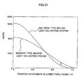
- a plurality of heliostats 12 are arranged to encircle the heat collector in the center similarly to a sunlight collecting system shown in FIG. 33 .
- each of the heliostats reflects the sunlight and collects the reflected sunlight to a light collecting point F1.
- the reflector group 11 includes a first reflector segment 21 and five reflector segments of a second reflector segment 22, a third reflector segment 23, a fourth reflector segment 24, a fifth reflector segment 25, and a sixth reflector segment 26 which are arranged below the first reflector segment 21.
- the first reflector segment 21 has a reflecting surface 21a which includes a portion of a first quadric of revolution HB1 whose focus (an upper focus) is located at the light collecting point F1 of the sunlight collected by the plurality of the heliostats 12.
- a reflecting surface 21 a of the first reflector segment 21 may be formed in a shape of a disc which is centered at a center line CL and cut out from the first quadric of revolution HB1, or a shape which is a portion cut out of the disc.
- the first reflector segment 21 may be formed in a shape of a ring in which a region including the center line CL is opened.
- the first reflector segment 21 may be formed in a shape of a circular ring or an arc which is a portion cut out from the circular ring.
- the second reflector segment 22, the third reflector segment 23, the fourth reflector segment 24, the fifth reflector segment 25, and the sixth reflector segment 26 respectively have reflecting surfaces 22a, 23a, 24a, 25a, and 26a placed along quadrics of revolution HB2, HB3, HB4, HB5, and HB6 which have the same focus with the first quadric of revolution HB1, that is, a confocus, at the light collecting point F1 and whose curvature radius are different from each other.
- the reflector group includes a number n (n is an integer greater than or equal to 2) of the reflector segments which are arranged along a direction from the light collecting point to the heat collector.
- the reflecting surfaces 22a, 23a, 24a, 25a, and 26a may be formed in a shape of a circular ring having as a center axis the center line CL which connects the light collecting point F1 with the center of the light collecting surface 13 of the heat collector, or a shape which is a portion cut out of the circular ring.
- the reflecting surfaces may be formed in a shape of a circular ring or an arc which is a portion cut out of the circular ring.
- the reflecting surfaces 21a, 22a, 23a, 24a, 25a, and 26a of the first reflector segment 21 through the sixth reflector segment 26 may be respectively formed by a portion of the quadric of revolutions HB1, HB2, HB3, HB4, HB5, and HB6 or may be formed by a tangential plane of the quadric of revolutions HB1, HB2, HB3, HB4, HB5, and HB6.
- the sunlight which converges on the light collecting surface 3 spreads to a certain extent caused by a parallactic angle (30 minutes) of the sun.
- the reflecting surfaces (22a, 23a, 24a, 25a, and 26a) of the reflector segments other than the first reflector segment 21 may be respectively formed by the tangential planes of the quadrics of revolution (HB2, HB3, HB4, HB5, and HB6). Then, it is possible to reduce the spreading of the light on the light collecting surface 13 caused by the parallactic angle (30 minutes) of the sun and the heliostats 12 formed in planes so that a light receiving portion of the heat collector can be downsized.
- each segment of the first reflector segment 21, the second reflector segment 22, the third reflector segment 23, the fourth reflector segment 24, the fifth reflector segment 25, and the sixth reflector segment 26 equalizes distribution of the collected light heat fluxes on the light collecting surface 13.
- the reflecting surfaces 21a, 22a, 23a, 24a, 25a, and 26a may be formed by curved surfaces which are formed by revolution of line segments about the center line CL.
- the segment lines may be inclined at a predetermined angle or moved in parallel by a predetermined distance in normal directions with respect to tangent lines of the quadrics of revolution HB1, HB2, HB3, HB4, HB5, and HB6.
- the spreading of the light on the light collecting surface 13 can be further reduced.
- the reflecting surfaces 21 a, 22a, 23a, 24a, 25a, and 26a can be formed by curved surfaces which are respectively formed by revolution of line segments which are inclined at approximately 0-+30 minutes (approximately 0-+30 minutes upward along the center line CL) or preferably approximately +15 minutes with respect to the tangent lines, about the center line CL.
- the spreading of the light on the light collecting surface 13 can be reduced.
- the spreading of the light on the light collecting surface can be reduced to a half.
- each of the reflecting surfaces 21a, 22a, 23a, 24a, 25a, and 26a may include a set of the plurality of the reflector units, as a whole.
- each of the reflector segments may include the set of the reflector units so that it is possible to arbitrarily adjust a shape and a form of each of the first reflector segment 21 through the sixth reflector segment 26.
- each of the reflector segments included in the reflector group 11 it is possible to select as needed an arrangement position, a form, an inclination, a curvature radius, and so on of each of the first reflector segment 21 through the sixth reflector segment 26 in accordance with an arrangement position and an arrangement area of a plurality of the heliostats 12, a position of the light collecting point F1, a position and an arrangement direction of the light collecting surface 13, and so on.
- the reflector segments which are included in the reflector group may be formed in a sector in accordance with light paths of the sunlight to be collected.
- the sunlight collected by the heliostats 12 can be reflected by the reflector segments so as to converge on the light collecting surface 13 of the heat collector.
- the light collecting point F1 of the sunlight collected from each of the heliostats 12 is located at a predetermined position in accordance with an inclination angle of the slope.
- the direction, the arrangement position, and so on of each of the reflector segments included in the reflector group 11 can be selected as needed in consideration of the position of the light collecting point F1 and the position of the light collecting surface 13 so as to make the sunlight converge on the light collecting surface 13.
- the direction and the arrangement position of each of the reflector segments included in the reflector group are adjusted.
- the light collecting point F1 of the sunlight collected by the heliostats 12 is adjusted. Accordingly, it is possible to make the sunlight converge on the light collecting surface 13.
- the first reflector segment 21 through the sixth reflector segment cause the sunlight which is reflected on the heliostats 12 to converge on the light collecting surface 13 without leaking so that a light collection efficiency becomes high.
- a space through which wind pass is formed between the first reflector segment 21 and the second reflector segment 22, between the second reflector segment 22 and the third reflector segment 23, between the third reflector segment 23 and the fourth reflector segment 24, between the fourth reflector segment 24 and the fifth reflector segment 25, and between the fifth reflector segment 25 and the sixth reflector segment 26.
- each of the reflectors can be small.
- a wind pressure which each of the reflectors receives becomes small so that the wind resistant design becomes simple.
- each of the reflectors can be simplified so that cost of construction can be reduced by 50% in comparison with a case where the reflector is formed by an only curved surface along a hyperboloid of revolution.
- the spreading of the light receiving surface in the heat collector decreases so that solar energy can be collected to a heat collector which is smaller than conventional one.
- incident light heat fluxes on the light receiving surface are controlled so that energy can be smoothed with equal heat fluxes.
- the first reflector segment 21-the sixth reflector segment 26 description has been given to an example where six reflector segments (the first reflector segment 21-the sixth reflector segment 26) are arranged.
- a plurality of reflector segments are preferably arranged without limitation in the number of the reflector segments which are arranged between the first reflector segment 21 and the light collecting surface 13 of the heat collector.
- the number of the installed reflector segments is not limited to the number in the embodiment.
- a required number of the reflector segments to be arranged is determined as needed in accordance with the number of the installed heliostats 12, a height of the first reflector segment 21 which is placed in the highest place, an allowable value of the spreading of the light on the light collecting surface 13, and so on. For instance, when the first reflector segment 21 is located in a high place, the radius of the circular ring which forms a reflector segment (the reflector segment located in the lowest place along the center line CL) located in the outermost periphery becomes small. Accordingly, the required number of the reflector segments is small.
- the first reflector segment 21 and the second reflector segment 22 through the sixth reflector segment 26 are arranged without overlapping each other on the light paths of the sunlight to be collected to the light collecting point F1 by the plurality of the heliostats (first reflectors) 12.
- the light paths of the sunlight which is collected to the reflecting surface of each of the reflector segments from the heliostats 12 and reflected by the outside edge of the reflector segment.
- the size, the shape, the curvature radius of the quadric of revolution, the arrangement position, and so on of the second reflector segment 22 through the sixth reflector segment 26 are determined so that the light paths of the sunlight reflected by each of the reflector segments do not intersect with the light paths of the sunlight reflected by the rest of the reflector segments.
- the reflecting surfaces of the reflector segments are arranged along the quadrics of revolution.
- the reflecting surfaces of the reflector segments used in the invention are not especially limited, and may be arranged along any kinds of curved surfaces as long as the curved surfaces can reflect the sunlight which is collected to the light collecting point by the plurality of the first reflectors and make the reflected sunlight converge on the light collecting surface.
- at least one kind of curved surface is selected from a hyperboloid of revolution and an ellipsoid of revolution as the quadric of revolution which is described in the embodiment as a concrete example of the curved surfaces on which the reflecting surfaces are arranged.
- All of the reflecting surfaces of the reflector segments may be arranged along the hyperboloids of revolution or the ellipsoids of revolution. Meanwhile, a part of the reflecting surfaces may be arranged along the hyperboloids of revolution, and the rest of the reflecting surfaces may be arranged along the ellipsoids of revolution. Moreover, when each of the reflector segments includes the set of the plurality of the reflector units, the reflector units included in the set may be arranged along at least one kind of curved surface selected from the hyperboloid of revolution and the ellipsoid of revolution.
- the reflector group including the reflector segments whose reflecting surfaces are arranged along the hyperboloid of revolution has a feature that the lights path from each of the heliostats to the light collecting point (the upper focus of the hyperboloid of revolution) and the light paths from the light collecting point to the light collecting surface are comparatively short.
- the feature is preferably used in a large-scale solar energy utilization system in which a lot of heliostats are arranged over a wide area and the reflector group is placed in the high place.
- a reflector group including the reflector segments whose reflecting surfaces are arranged along the ellipsoid of revolution has a feature that the light paths from each of the heliostats to the light collecting point (the upper focus of the ellipsoid of revolution) and the light paths from the light collecting point to the light collecting surface (the lower focus of the ellipsoid of revolution) are relatively long.
- the feature is preferably used in a small-scale solar energy utilization system in which the reflector group is placed in the low place.
- FIG. 16 is a schematic diagram showing an example of a solar energy utilization system according to a sixth embodiment, which uses the sunlight collecting reflector according to the fifth embodiment of the invention.
- the solar energy utilization system shown in FIG. 16 includes a heliostat (a first light collecting system) FC, a second light collecting system SC, a third light collecting system (CPC) 57, a solar heat collector 51, a high-temperature heat exchange medium tank 52, a heat exchanger 53, a low-temperature heat exchange medium tank 54, and a heat exchange medium purification system 55.
- the solar heat collector 51, the high-temperature heat exchange medium tank 52, the heat exchanger 53, the low-temperature heat exchange medium tank 54, and the heat exchange medium purification system 55 are connected with each other by flow paths through which heat exchange medium circulates.
- valves, pumps, and so on are arranged in places.
- the second light collecting system SC includes the sunlight collecting reflector according to the invention, which includes a reflector group which includes a plurality of reflector segments.
- the third light collecting system (CPC) 57 which is opened towards the reflector groups may be included above the solar heat collector 51.
- the third light collecting system (CPC) 57 does not need to be included above the solar heat collector 51.
- sunlight irradiates an inner surface of the light receiving surface through an opening which is opened upward.
- the sunlight is collected by the heliostats FC and reflected by the second light collecting system SC (the sunlight collecting reflector of the invention) so as to converge on the light collecting surface 3.
- the light collecting surface 3 is preferably located at the opening of the third light collecting system (CPC) 57.
- the light collecting surface 3 is preferably located at the opening of the solar heat collector 51.
- the high-temperature heat exchange medium tank 52, the heat exchanger 53, the low-temperature heat exchange medium tank 54, and the heat exchange medium purification system 55 are not especially limited and can be selected in accordance with heat exchange medium to be used, capacity, purity requirement of the heat exchange medium, and so on, as needed.
- the sunlight SB from the sun S is collected by the first light collecting system FC to the sunlight collecting reflector SC which is the second light collecting system.
- the collected sunlight SB is further collected to the solar heat collector 51 by the sunlight collecting reflector SC and introduced through the sunlight inlet 56 of the solar heat collector 51.
- the introduced sunlight SB irradiates the light receiving surface of the solar heat collector 51.
- the heat exchange medium which is placed on the light receiving surface is heated.
- the heated heat exchange medium which stores thermal energy is sent out through the heat exchange medium outlet in the lower portion of the heat collecting element 51.
- the heat exchange medium sent out through the heat exchange medium outlet is sent to the high-temperature heat exchange medium tank 52 through the flow path.
- the heat exchange medium sent to the high-temperature heat exchange medium tank 52 is supplied to the heat exchanger 53 to supply the thermal energy to a heat utilization facility which is connected with the heat exchanger 53.
- the heat utilization facility performs steam turbine power generation, pyrolysis of hydrocarbon, production of liquid fuel from natural gas and coals, or the like.
- a part of the thermal energy of the heat exchange medium is exchanged by the heat exchanger 53 to lowe r a temperature of the heat exchange medium. Then, the heat exchange medium is sent to and temporarily stored in the low-temperature heat exchange medium tank 54. And, the heat exchange medium with a low temperature which is temporarily stored in the low-temperature heat exchange medium tank 54 is purified by the heat exchange medium purification system 55 and supplied to the solar heat collector 51, again.
- the thermal energy of the sunlight obtained by the sunlight collecting reflector of the invention for a reforming reactor
- the thermal energy is applied to a process for producing synthesis gases (CO and H 2 ) by reaction of methane CH 4 with water H 2 O
- the reforming reactor is replaced in the same position with the solar heat collector 51.
- incident light heat fluxes on the light receiving surface can be controlled to smooth energy with equal heat fluxes, the thermal energy is effective for use in the reforming reactor.
- a seventh embodiment of the invention will be described in detail referring to the accompanying drawings as needed.
- a light collecting system in a tower method is installed in the northern hemisphere.
- a heat collector is placed at a light collecting point.
- first heliostats and second heliostats are arranged reversely in the north-south direction to the heliostats in the seventh embodiment described below.
- a light collecting reflector is placed near the light collecting point. Then, the light collecting reflector reflects sunlight downward to the ground and collects the reflected sunlight to the heat collector near the ground.
- the beam-down light collecting system has the same structure with the following seventh embodiment, and therefore will not be discussed.
- FIG. 17 is a schematic diagram showing a sunlight collecting system according to the seventh embodiment of the invention.
- the sunlight collecting system 31 includes a heliostat group A and a heliostat group B.
- the heliostat group A includes a plurality of first heliostats 32 which collect sunlight SB to a light collecting point Fa.
- the heliostat group B includes a plurality of second heliostats 33 which collect the sunlight SB to a light collecting point Fb located on a north side of the light collecting point Fa.
- the first heliostats 32 and the second heliostats 33 are arranged so that light paths of reflected light B2 by the plurality of the first heliostats 32 included in the heliostat group A and light paths of reflected light B3 by the plurality of the second heliostats 33 included in the heliostat group B are formed respectively toward the light collecting points Fa and Fb of the heliostat groups to which the first and second heliostats belong.
- the first heliostats 32 are arranged fixedly on the ground so that reflecting surfaces 2a shown in FIG. 18 (a) are directed to face the sun and the light collecting point Fa.
- direction of the reflecting surface 2a is adjusted so that the incident sunlight is symmetry with the reflected light which reaches the light collecting point Fa, about a normal line of the reflecting surface 2a.
- the first heliostat 32 includes the reflecting surface 32a, a frame 32b which has the reflecting surface 32a on one side, a support column 32c which is erected on the ground to support the frame 32b.
- metal may be evaporated on a side of a transparent substrate made of glass, transparent plastic, and so on to form a reflective film.
- the reflecting surface 32a may be formed by a reflecting element including the reflective film to have a required shape and area.
- the reflecting surface 32a can follow the sun in accordance with changes in a day and seasonal changes in sun elevation, so as to be directed to face the sun and the light collecting point Fa.
- a support axis 32d which is supported by the support column 32c to span the frame 32b may freely rotate in an axial direction and a direction perpendicular to the axial direction.
- the first heliostat 32 may include a solar battery which accompanies the reflecting surface 32a. Then, the solar battery can supply power to rotate the frame 32b and cause the reflecting surface to follow the sun.
- the second heliostats 33 are arranged so that the reflecting surfaces 33a are directed to face the sun and the light collecting point Fb. In other words, in the second heliostat 33, direction of the reflecting surface 33a is adjusted so that the incident sunlight SB is symmetry with the reflected light RB3 which reaches the light collecting point Fb, about a normal line of the reflecting surface 33a.
- the second heliostat 33 includes a reflecting surface 33a, a rotation axis 33b by which the reflecting surface 33a is rotatably pivoted, a support frame 33c which is transversely spanned by the rotation axis 33b, a rotation support 33d which pivots the support frame 33c, and a base 33e which supports the rotation support 33d.
- the reflecting surface 33d is rotated about the rotation axis 33b as a center axis in order to adjust an angle ⁇ of the reflecting surface 33a in the vertical direction.
- the rotation support 33d is rotated in order to adjust an angle ⁇ of the reflecting surface 33a in the horizontal direction.
- a drive motor and so on not shown in the figure may drive the rotation axis 33b and the rotation support 33d.
- the second heliostat 33 may include a running drive means such as a moving wheel in a lower portion of the base 33e. Then, the second heliostat 33 itself can autonomously move to a required position with the running drive means. Accordingly, the second heliostat can autonomously move to a position to avoid shadows made by the first heliostat 32, in accordance with changes in a day and seasonal changes in the sun elevation.
- the angle ⁇ and the angle ⁇ of the reflecting surface 33a are adjusted by the rotation axis 33b and the rotation support 33d so that the sunlight can be reflected and collected to the light collecting point Fb.
- the second heliostat 33 also may include a solar battery similarly to the first heliostat 32. Thus, the solar battery can supply power to drive the rotation axis 33b, the rotation support 33d, and the running drive means.
- the second heliostats 33 are arranged in places where none of the first heliostats 32 is placed and the sunlight irradiates the ground. Accordingly, the second heliostats can eliminate places where the sunlight irradiates the ground between the plurality of the first heliostats 32 included in the heliostat group A, that is to say, blocking. Therefore, the second heliostats 33 are arranged between the first heliostats 32.
- a field efficiency which is a ratio of a light quantity of the sunlight which can be used as energy, becomes almost 100% with respect to a total light quantity of the sunlight which irradiates the region where the heliostats are arranged.
- the second heliostats 33 are arranged nearer to the ground than the first heliostats 32.
- the second heliostats 33 being arranged in the positions nearer to the ground than the first heliostats 32 means that the reflecting surfaces 33a of the second heliostats 33 are installed in lower positions and nearer to the ground, comparing with the reflecting surfaces of the first heliostats 32.
- the second heliostat 33 can be densely arranged in regions where the ground is irradiated by sunlight which is unused due to the blocking. Therefore, there are no more regions where the ground is irradiated by sunlight which is unused due to the blocking. Thus, almost all of the sunlight which irradiates the region where the heliostats are arranged can be collected to the plurality of the light collecting points. As a result, it is possible to improve a light collection efficiency of the entire light collecting system.
- the plurality of the heliostats 33 are arranged in series and parallel in the places where the sunlight irradiates the ground, to cover the places.
- the second heliostats 33 it is possible to adjust the angles ⁇ and ⁇ of the reflecting surface 33a in the vertical and horizontal directions in accordance with changes in the sun elevation.
- the second heliostat 33 can move using the running drive means in the lower portion of the base 33e so as to avoid the shadows of the first heliostats 32 and the adjacent second heliostat 33.
- the second heliostat 33 can change a position and move the reflecting surface 33a of the second heliostat 33 itself in order to follow the sun in accordance with a time during a daytime and a season, so as to receive the maximum sunlight. Therefore, the second heliostat can move to a position where shadows which are made by the first heliostats and hourly change with changes in elevation of the sun during a day and seasonally. As a result, the light collection efficiency can be improved.
- FIG. 19 shows results of simulating hourly changes of the shadow of the first heliostat 32 and movement of the second heliostat 33 when the second heliostat 33 moves to the position to avoid shadows of the first heliostats, which hourly change with changes in elevation of the sun during a day and seasonally.
- the second heliostat 33 can move so as to avoid the shadows of the first heliostats 32 to collect the sunlight. Therefore, the second heliostat is effective to improve the light collection efficiency.
- FIG. 20 illustrates relationship between incident light and reflected light from the sun S to a tower T (a triangular pole on the right) and concepts of a shadow and interference of the reflected light (blocking) caused by the first heliostat 32.
- each of the heliostats is formed by a mirror, for simplicity.
- unit vectors e1, e2, and n are respectively a sun direction vector, a tower direction vector, and an outward normal vector of the heliostat.
- a length of shadow (a shadow length) and a length of blocking (a blocking length) can be obtained by calculation using these vectors and lengths of sides of the heliostats.
- the blocking length is a distance between two arranged first heliostats when light which is reflected by a lower end of a first heliostat 32 further from the tower passes an upper end of a first heliostat 32 nearer to the tower, on the way to travel towards the tower T.
- the both heliostats are arranged being separated from each other by this distance, no light interference occurs caused by the blocking.
- FIG. 21 shows relationship among a position and a shadow length of the heliostat, the blocking length, and a light quantity which the heliostat can collect per field unit area, in a case of one tower.
- a coordinate axis (y) has an origin at the tower T in the north-south direction supposing that a positive direction is south. It is supposed that the sun culminates.
- a height H of the tower (a height of the light collecting point) is 120m, and a sun elevation ⁇ is 45 degrees.
- the shadow length (indicated by a dashed line in the figure) is longer than the blocking length (indicated by an alternate long and short dash line in the figure) in a range around the tower T, that is, a range where the following expression is satisfied.
- y ⁇ L Hcot ⁇
- the shadow length is shorter than or equal to the blocking length in a region outside the range, that is, in a range where the following expression is satisfied.
- adjacent heliostats in the north-south direction need to be arranged in such a way to be separated from each other by a distance longer than the shadow length to avoid light interference between the heliostats to improve an efficiency of specular surface.
- the adjacent heliostats need to be arranged in such a way to be separated from each other by a distance longer than the blocking length.
- these features indicates that the second heliostats 33 which include specular surfaces 33a formed by strip-shaped mirrors (Fazet 33f) arranged with a predetermined intervals are effectively arranged to cover a region expressed by the following expression. y ⁇ Hcot ⁇
- the blocking length is long and greatly changes depending on the position. Therefore, it is not appropriate to arrange the second heliostats 33 in the region, but it is advantageous to arrange the first heliostats 32 there.
- the second heliostats are preferably arranged as described below. More specifically, the second heliostats 33 for the second tower are arranged between the first heliostats 32 which collect light to the first tower. In other words, it is advantageous to interplace the second heliostats 33 in a periphery of the tower where the shadow length is longer than the blocking length.
- the second heliostats 33 are arranged. - L ⁇ y ⁇ L ⁇
- the first heliostats 32 are arranged in such a way to be separated from each other by the blocking length.
- the second heliostats 33 which collect light to the second tower are interplaced between the first heliostats 32 in consideration of the light interference.
- the second heliostats 33 which collect light to the second tower are arranged. - 4 ⁇ L - L ⁇ ⁇ y ⁇ - L
- optimal values are selected for a distance 4L between the first tower and the second tower and a distance L' between each of the towers and the north or south end, that is, coordinates for the two towers.
- N n N s ⁇ B ⁇ L s - S ⁇ L s M ⁇ a ⁇ x S ⁇ L n , B ⁇ L n
- N is the number of the heliostats per field unit length
- BL is the blocking length
- SL is the shadow length.
- n and a subscript s indicate respectively the second heliostat (which collects light to the second tower (on the north side)) and the first heliostat (which collects light to the first tower).
- FIGS. 22(a) and 22(b) are diagrams illustrating arrangement of heliostat groups A and heliostat groups B in a sunlight collecting system according to an eighth embodiment of the invention.
- each of light collecting systems includes the heliostat groups A and the heliostat groups B which are arranged so that a plurality of light collecting points F1, F2, F3, ..., and FN are formed and arranged in the north-south direction.
- a multiple rows of the light collecting systems are arranged with appropriate intervals in the east-west direction.
- a heliostat group B h1 (h1 is an integer greater than or equal to 1) and a next heliostat group A k1 (k1 is an integer greater than or equal to 2) form one light collecting point.
- a required number of light collecting points can be formed in series in the north-south direction with almost equal intervals so that the other light collecting point Fb is formed on the north side of the one light collecting point Fa. Therefore, a required quantity of sunlight can be efficiently collected even in a long and slender region regardless of an area of the region where the heliostats are arranged.
- the heliostat groups may be arranged so that a plurality of light collecting points are formed to stagger every row so as to reduce influence of the shadows.
- FIGS. 23(a) and 23(b) are diagrams illustrating arrangement of light collecting points and heliostat groups in a sunlight collecting system according to a ninth embodiment of the invention.
- the sunlight collecting system includes a unit 41 which includes regions A2 and A3 (fields) where the heliostat groups including first heliostats are arranged, regions A1 and A4 (fields) where the first heliostats and second heliostats are mixed and arranged.
- three light collecting points F1, F2, and F3 are formed by the heliostat groups included in the unit 41 to be located at vertices of a triangle D.
- the base of the triangle D is a line which connects the light collecting point F2 with the light collecting point F3 and directed in the east-west direction. Moreover, the light collecting point F1 is located at the apex of the triangle D. Since contour lines of a light collection efficiency are formed in similar shapes to an elongate oval in the north-south direction, it is effective for improving the light collection efficiency that the triangle D is an isosceles triangle whose base is directed in the east-west direction.
- the first heliostats are arranged to select the light collecting point to maximize a quantity of collected light.
- the second heliostats are arranged in the regions where the blocking occurs.
- light can be collected to the light collecting point which maximizes the quantity of the collected light on the north side of the heliostats.
- the second heliostats can form an optimal light collecting point at any time in accordance with changes during a day and seasonal changes in an irradiation angle of the sunlight. Consequently, the quantity of the collected light in a year can be maximized comparing with the light collecting system where heliostats are fixed.
- the units each of which forms the three light collecting points F1, F2, and F3 may be arranged in a triangular lattice in the east-west direction and the north-south direction.
- the units are arranged in the triangular lattice in the east-west direction and the north-south direction, it is possible to improve an efficiency of the light collection in a field in an almost circle or square shape.
- the towers are arranged to stagger every row, influence of the shadows can be reduced.
- the arrangement can be optimized as needed in accordance with geographical conditions such as an area, an inclination, and a shape of a place where the first heliostats, the second heliostats, and heat collectors or light collecting reflectors are installed. Therefore, the structure is effective in a case of constructing a highly flexible and commercially large-scale sunlight collecting system.
- first heliostat and the second heliostat may have different forms.
- a first heliostat and a second heliostat may have the identical form.
- the first heliostat and the second heliostat may have a form shown in FIG. 18(a) to form a heliostat group.
- a plurality of heliostats with the form shown in FIG. 18(a) may be arranged to form a heliostat group A.
- another heliostat group B may include another plurality of heliostats with the form shown in FIG.
- the other heliostat group B may be formed in a place where the sunlight irradiates the ground between the arranged heliostats with the form shown in FIG. 18(a) , so that the sunlight is collected to another light collecting point Fb. Thus, a light collecting system can be formed.
- heliostats with the form shown in the FIG. 18(b) may be used as a first heliostat and a second heliostat to form a plurality of heliostat groups.
- a heat collector or a light collecting reflector may be placed at each of the light collecting points formed by the plurality of heliostat groups in the sunlight collecting system. Then, energy of collected sunlight can be collected by the heat collector or a heat collector under the light collecting reflector. Accordingly, it is possible to collect with a high field efficiency the sunlight which irradiates the region where the heliostats are installed and highly efficiently use thermal energy of the collected sunlight.
- a solar energy utilization system which includes a sunlight collecting system, a solar heat collector, a high-temperature heat exchange medium tank, a heat exchanger, a low-temperature heat exchange medium tank, and a heat exchange medium purification system. Then, the sunlight collecting system according to the invention may be used as the sunlight collecting system.
- the solar energy utilization system sunlight is collected by the sunlight collecting system, and the collected sunlight is further collected by the solar heat collector so that energy of the sunlight is collected.
- the energy of the sunlight heats heat exchange medium in the solar heat collector and is collected in the heated heat exchange medium which stores thermal energy.
- the heat exchange medium is supplied to the heat exchanger and supplies thermal energy to a heat utilization facility which is connected with the heat exchanger.
- the heat utilization facility performs steam turbine power generation, pyrolysis of hydrocarbon, production of liquid fuel from natural gas and coals, or the like.
- the solar heat collector according to the first or third embodiment may be used as a solar heat collector. Accordingly, the solar heat collector of the first or third embodiment is used as the heat collector to highly efficiently collect energy of the sunlight which is collected with a high field efficiency by the heliostat groups. As a result, the thermal energy of the sunlight can be highly efficiently used.
- the sunlight collecting reflector according to the fifth embodiment of may be used as a sunlight collecting reflector in the solar energy utilization system.
- the sunlight is collected with a high field efficiency by the plurality of heliostat groups including a plurality of first reflectors.
- the sunlight collecting reflector makes the collected sunlight efficiently converge on the heat collector so that the thermal energy of the sunlight can be highly efficiently used.
- the solar heat collector according to the first or third embodiment may be used as the solar heat collector
- the sunlight collecting reflector according to the fifth embodiment may be used as the sunlight collecting reflector.
- sunlight reflected by a plurality of first reflectors to a light collecting point can be efficiently collected to the heat collector by the sunlight collecting reflector.
- the collected sunlight can converge on the solar heat collector according to the first aspect A of the present invention. Accordingly, energy of the converging sunlight is highly efficiently stored in the heat exchange medium, and the stored thermal energy can be used.
- any forms of systems such as a Rankin cycle type system which uses a steam turbine, an open Brayton cycle system which uses a gas turbine, and so on are applicable to a power generation system using solar energy.
- the power generation system can be selected as needed in accordance with various conditions such as an entire structure of the solar energy utilization system, a purpose to use the solar energy, and geographical conditions. For instance, in a system whose main purpose is power generation, all of the thermal energy of the sunlight stored in the heat exchange medium by the solar heat collector can be used as energy to drive a power generator.
- the energy of the sunlight can be shared between the power generation system and the other system in consideration of how to use energy, a temperature of the heat exchange medium, and so on so that the thermal energy of the sunlight can be efficiently used.
- FIG. 24 shows a concrete example of an open Brayton cycle power generation system (a solar gas turbine system) which uses solar energy as a thermal energy source of the power plant including a gas turbine (Sinai, J. et al., "Adaptation and modification of gas turbines for solar energy applications", GT 2005-68122, proc. ASME Turbo Expo 2005, 2005).
- a gas turbine Silicon turbine
- the solar gas turbine system can achieve a higher power generation efficiency than that in the Rankine cycle system which uses the steam turbine as a working medium.
- a solar gas turbine system 70 shown in FIG. 24 includes a compressor 71 which intakes and compresses the outside air, and a turbine 72 and a power generator 73 which perform expansion work. Moreover, sunlight is reflected by a plurality of reflectors (heliostats: not shown) arranged on a surface of the ground and collected to a photoreceptor 74 (a receiver) on a top of the tower. Heat of the collected sunlight directly heats high-pressure air supplied from the compressor 71 to the photoreceptor 74 to generate high-temperature and high-pressure air. The generated high-temperature and high-pressure air is introduced into the turbine 72, and performs the expansion work so that power is generated by the power generator 73 directly connected with an axis of the turbine 72.
- a plurality of reflectors heliostats: not shown
- the generated power output is (the shaft power output of the turbine) - (the required shaft power output of the compressor).
- exhaust air from the turbine is diffused into the air after the turbine has ended the expansion work.
- a temperature of the high-temperature and high-pressure air is 1000°C or higher in an inlet 72a of the turbine. Therefore, for instance, the heat exchange material included in the photoreceptor 74 is preferably heat resistant alloy. Moreover, the working medium (air) of the turbine is directly heated by the heat of the collected sunlight to operate the turbine. Accordingly, it is preferred that not only during daytime when the sunlight irradiates, but even during nighttime, the thermal energy of the sunlight stored in the heat exchange medium during daytime or energy in a combustor 75 shown in FIG. 24 is used to heat the working medium and the heated working medium is supplied to the turbine.
- a bypass isolates the system in emergency to stop supply of heat or controls the temperature of the working medium in the inlet 72a of the gas turbine.
- carbon dioxide in a supercritical state is used as working medium to supply a part of the stored thermal energy to a gas turbine power plant to generate power.
- the gas turbine power generation system 100 shown in FIG. 25 includes a solar heat collector 101, a molten salt heat exchanger 102, a turbine 103, and a power generator 104.
- the gas turbine power generation system 100 further includes a regenerative cycle including a regenerative heat exchanger 105, a precooler 106, a low-pressure compressor 107, an intercooler 108, and a high-pressure compressor 109 between an exit 103a of the turbine 103 and an inlet 102a of the molten salt heat exchanger 102.
- thermal energy of sunlight stored in molten salt is used as a heat source to drive a gas turbine cycle.
- carbon dioxide working medium
- the working medium (the carbon dioxide) whose temperature becomes high is cooled again close to the critical temperature by the intercooler 108 and then compressed by the high-pressure compressor 109 to be in a supercritical state.
- exhaust heat of exhaust gas purged from the exit 103a of the turbine 103 is collected in the regenerative heat exchanger 105 and raises the temperature of the working medium (the carbon dioxide in the supercritical state).
- the working medium takes the thermal energy of the sunlight stored in the molten salt in the solar heat collector 101. Therefore, the temperature of the working medium is further raised. Then, the working medium is introduced into the turbine 103 to perform expansion work so that the temperature of the working medium falls. The working medium exhausted from the exit 103a of the turbine 103 transfers the thermal energy of the exhausted air to the gas purged from the exit of the high-pressure compressor 109 in the regenerative heat exchanger 105. Afterwards, the working medium is cooled close to the critical temperature in the precooler 106, and supplied again to the low-pressure compressor 107.
- the carbon dioxide in the supercritical state in the invention means carbon dioxide in a state with a pressure higher than or equal to a critical pressure (7.375MPa).
- the intercooler 108 lowers the temperature of the working medium in the inlet of the high-pressure compressor 109 so as to reduce compression work in the high-pressure compressor 109.
- the thermal energy of the exhaust gas with a high temperature from the turbine 103 is collected within the cycle to save a quantity of supplied heat so that a thermal efficiency of the gas turbine cycle is improved.
- the thermal energy of the sunlight which is collected in the solar heat collector 101 is stored in the heat storage medium.
- a part of the thermal energy is used to generate power in the gas turbine power generation system 100 through the molten salt heat exchanger 102. Therefore, the system can generate power for 24 hours at a constant output regardless of daily changes in quantity of solar radiation.
- the closed gas turbine cycle in which the carbon dioxide in the supercritical state is used as the working medium is effective for the gas turbine cycle which is more efficient than the steam turbine and is operated within a temperature range (a middle temperature ⁇ 1000°C) within which the working medium is usable.
- the thermal efficiency value of the cycle is significantly dependent on a temperature efficiency of the regenerative heat exchanger 105.
- a PCHE Print Circuit Heat Exchanger
- the temperature efficiency which is approximately 0.85 in a common heat exchanger due to an economical restriction, can increase to 0.95 or higher.
- the PCHE can be a compact heat exchanger, effective for cost reduction, and highly pressure resistant.
- the PCHE which has features of high heat transfer performance and a low pressure loss, may be used as the intermediate heat exchanger 108 or the regenerative heat exchanger 105 so as to achieve highly efficient heat transfer at low-cost.
- the regenerative heat exchanger 105 with the temperature efficiency of 95% can surpass a conventional solar gas turbine (an open Brayton cycle).
- the temperature efficiency of the regenerative heat exchanger 105 is preferably 98%.
- Either one of an axial-flow type and a centrifugal type may be used as the compressor (the low-pressure compressor 107 or the high-pressure compressor 109).
- the axial-flow compressor an adiabatic efficiency is high, but force which presses a wing is large since density of the working medium is high. Therefore, the axial-flow compressor might not be allowed in view of mechanical strength.
- the compressors (the low-pressure compressor 107 and the high-pressure compressor 109) which use the carbon dioxide as the working medium are operated in a range where a compressibility coefficient is small so that work of the compressors is small. Therefore, the adiabatic efficiency of the compressor only a little influences the cycle thermal efficiency.
- the centrifugal compressor which is robust in mechanical strength, is preferably used as the compressor.
- an axial-flow turbine which generates a large amount of work, is preferably used as the turbine 103.
- W C is as much as 3/5 of W T .
- FIG. 26 shows how a compressibility coefficient z of the carbon dioxide is dependent on a temperature and pressure.
- a triangular mark shows the critical point.
- FIG. 26 shows preferable operating regions of the compressors (the low-pressure compressor 107 and the high-pressure compressor 109) and the turbine 103. It is understood that improvement of the efficiency of the gas turbine can be expected in consideration of the expression (1) and the expression (2).
- a value inversely calculated from an optimal pressure ratio of the regenerative cycle and a pressure of the working medium in the inlet of the compressors (the low-pressure compressor 107 and the high-pressure compressor 109) is used as the pressure of the working medium in the inlet of the turbine 103.
- FIG. 25 there is shown an example of provisional estimations of thermal balance in the gas turbine power generation system including the intermediate heat exchanger 108 and the regenerative heat exchanger 105.
- values shown in FIG. 25 are respectively a quantity of exchanged heat in the molten salt heat exchanger 102, temperatures of the working medium in the inlets of the low-pressure compressor 107 and the high-pressure compressor 109, and a temperature and pressure of the working medium in the inlet of the turbine 103.
- an adiabatic efficiency of the compressor and the turbine 103 are respectively supposed to be fixed to 0.9 and 0.93.
- a temperature efficiency of the regenerative heat exchanger 105 is supposed to be fixed to 98%.
- the expansion ratio of the turbine is used as a parameter to calculate the thermal balance.
- a power output is 23.6 MW. Therefore, the cycle thermal efficiency is 47.2% so as to exceed a cycle efficiency (33%) of the Brayton cycle shown in FIG. 24 as well as an efficiency (39%) of a conventional steam turbine.
- FIG. 27 is a diagram showing a relationship of specific power-cycle thermal efficiency in the gas turbine power generation system (RC+IC cycle in FIG. 27 ) which is shown in FIG. 25 including the regenerative heat exchanger and the intermediate heat exchanger 108 and the gas turbine power generation system (IC cycle in FIG. 27 ) which does not include the regenerative cycle, under a condition where the temperature of the working fluid in the inlet of the turbine is 800K (527°C).
- the thermal efficiency is maximized (26%), and the specific power is also large.
- FIG. 28 shows how the cycle thermal efficiency is dependent on an expansion ratio.
- the expansion coefficient which maximizes the thermal efficiency is 1.55. Therefore, it is enough possible to produce a turbine with such an expansion coefficient.
- the specific power decreases to about 50% of the IC cycle. Therefore, the gas turbine power generation system is appropriate for a gas turbine whose generated power output is small or medium scale and preferably applied for solar utilization. It is understood that the pressure of the working medium in the inlet of the turbine 103 is optimized near 20MPa.
- FIG. 29 is a diagram showing how the temperature efficiency of the regenerative heat exchanger influences the cycle thermal efficiency.
- Specific heat duty of recuperator beside the right ordinate axis in FIG. 29 and Specific Qrecup in the diagram indicates specific heat load of the regenerative heat exchanger.
- the specific heat load is large, the regenerative heat exchanger can be small to achieve a required heat exchange.
- the gas turbine power generation system can realize the features of the gas turbine power generation system (RC+IC cycle in FIG. 27 ) which includes the regenerative heat exchanger 105, in combination with a highly efficient regenerative heat exchanger.
- the PCHE Print Circuit Heat Exchanger
- a total capacity of a shell-and-tube heat exchanger is 125m 3
- a total capacity of a PCHE is 10 m 3 , that is, 1/12 of the shell-and-tube heat exchanger. Therefore, the PCHE is advantageous in both sides of a space for installing equipments and cost.
- flow paths with a hydraulic diameter of approximately 0.6mm are cut by an etching process on a metallic plate with a thickness of 1mm.
- the PCHE is thus formed heat exchanger.
- the PCHE has high heat and pressure resistance, and is preferably used in a supercritical CO 2 gas turbine cycle system which operates in a high temperature and pressure.
- the thermal energy of the sunlight which is stored in the molten salt is once stored in the heat storage medium in the solar heat collector 101. Then, a part of the thermal energy is supplied to a gas turbine power plant to continuously generate power for 24 hours.
- the gas turbine cycle is a regenerative cycle which includes the intermediate heat exchanger 108 and uses the carbon dioxide in the supercritical state as the working medium.
- the system can operate within an operating temperature range (a middle temperature) of the heat storage medium to obtain a higher power generation efficiency than that of the Rankine cycle.
- the gas turbine solar thermal power generation system with such features can construct a power generation system which is competitive against existing power supplies which generate no carbon dioxide.
- FIG. 30 shows a concrete example of a solar energy multiple utilization system which combines a gas turbine power generation system with a chemical plant.
- a heliostat 111 reflects sunlight energy. And, a center reflector 112 collects the reflected sunlight. Then, a solar heat collector 113 receives the collected sunlight. After that, thermal energy of the received sunlight is stored in molten salt, and energy is supplied to the gas turbine power generation system and the chemical plant. Thus, the solar energy multiple utilization system performs power generation and chemical processes.
- FIG. 30 shows a system including the center reflector 112. However, in a case where there is no center reflector, a tower-up method, in which the solar heat collector is located in a high place, may be employed instead.
- heat storage material such as the molten salt is supplied from a low-temperature heat storage container 114 to a solar heat collector 113 by a pump P3. After that, the heat storage material absorbs the thermal energy of the sunlight received by the solar heat collector 113 so as to have high temperature and then is supplied and stored in a high-temperature heat storage container 115 by a pump P1. Moreover, the heat storage material with the high temperature is supplied to a first heat storage material heat exchanger 116 and supplies thermal energy to carbon dioxide which has collected waste heat of exhaust gas from a turbine 118 through a regenerative heat exchanger 117.
- the heat storage material supplies the thermal energy to a chemical plant cycle which supplies heat to a chemical process, seawater desalination, or the like. After that, the heat storage material with a predetermined temperature returns to the low-temperature heat storage container 114.
- the carbon dioxide heated in the first heat storage material heat exchanger 116 performs expansion work in the turbine 118. Then, the power generator 120 converts a part of or almost all of the expansion work into electric energy.
- the exhaust gas (the working fluid) which has finished the expansion work in the turbine 118 supplies a part of the thermal energy to the working medium compressed by a compressor 121. After that, the exhaust gas is cooled to a predetermined temperature in a cooler 122, and introduced into the compressor 121.
- the working medium, which is compressed by the compressor 121 and heated by the regenerative heat exchanger 117, is introduced into the first heat storage material heat exchanger 116, and heated by the solar thermal energy so that a gas turbine power generation cycle comes back around.
- the compressor 121 is preferred to be an intercooling (IC) cycle including the low-pressure compressor 107, the intermediate heat exchanger 108, and the high-pressure compressor 109 shown in FIG. 25 in order to improve specific power.
- IC intercooling
- a part of the working medium cooled by the cooler may be branched to a third compressor.
- compressed working medium may be introduced to the regenerative heat exchanger.
- the thermal energy supplied from the high-temperature heat storage container 115 to the first heat storage material heat exchanger 116 is controlled to supply a predetermined quantity of thermal energy to the first heat storage material heat exchanger 116 for 24 hours. Therefore, power can be generated to output constant power even during a nighttime.
- the fossil fuel is combusted to heat the working medium (the carbon dioxide) in the first heat storage material heat exchanger 116 to auxially supply heat.
- the chemical plant include a plant which heats and vaporizes CMM (slurry) in a coal gasification process, or seawater desalination which generates steam with heat.
- the thermal energy can be used as a heat source for these chemical plants.
- a Rankine cycle can be constructed as a power generation system.
- the heat storage medium is preferably alkali nitrate (for instance, equimol solution of NaNO 3 and KNO 3 ) at an operating temperature of 600°C or lower.
- metallic sodium may be used as the heat storage medium at an operating temperature of 600°C or higher.
- a melting point and boiling point of the metallic sodium are, respectively, approximately 80°C and 850°C so as to remain liquid in a wide temperature range.
- thermal conductivity of the metallic sodium is extremely high. Therefore, the metallic sodium is appropriate for the heat transfer medium.
- the metallic sodium can be used at a higher temperature than the molten salt.
- cycle thermal efficiency of the gas turbine cycle is higher comparing with a case of using molten salt nitrate. Furthermore, chemical reaction of the metallic sodium with carbon dioxide occurs slowly. Thus, even if the sodium directly contact with the carbon dioxide, no explosion occurs or no high heat is generated so that the metallic sodium is safe.
- Table 1 shows main parameters in a commercial-scale light collecting system (for a practical use) for solar energy utilization and a light collecting system (for an experiment) which performs a demonstration test of commercial-scale solar energy utilization.
- FIG. 31 shows hyperboloids of revolution (as shown by a dashed line in a diagram) and a structure example of reflector segments which are arranged along the hyperboloids of revolution in the light collecting system for a practical use.
- point A is a point irradiated on the hyperboloid of revolution by a light beam which comes from the center of the sun and is reflected on the center of the fifth heliostat (a serial number 67: see an abscissa axis in FIG. 32 ) from the outside.
- FIG. 32 shows radial direction coordinates when light beams from the heliostats with serial numbers 63-71 (see the abscissa axis in FIG. 32 ) are reflected on the truncated cone surface and pass through the lower focal plane (the light collecting surface).
- a second reflector including a reflector group constituted of a plurality of reflector segments spreading of light on the light collecting surface is smaller comparing with a second reflector including one reflector formed along a hyperboloid of revolution.
- the second reflector segment reflects sunlight collected by heliostats (first reflectors) and makes the reflected sunlight converge on the light collecting surface.
- FIG. 33 shows radial distribution of heat fluxes on the light collecting surface in a case of using a sunlight collecting reflector according to the invention in comparison with a conventional case.
- a light collecting power in a case of using the sunlight collecting reflector according to the invention comparatively decreases in the center.
- the light collecting power comparatively increases on the periphery (a region where a position coordinate in a lower focal plane is large: a portion from the center of the light collecting surface to the outside).
- the equalized heat fluxes shown in the distribution are preferably used as energy of a reforming reactor and the like.
- the distribution has a feature of heat fluxes to realize a spatially equal distribution of temperatures.
- FIG. 34 shows a structure example of a reflector group including reflector segments formed along ellipsoids of revolution which meet a condition that heights of an upper focus and a lower focus are respectively 140m and 25m.
- the reflector group shown in FIG. 34 shows an example where portions (portions indicated by heavy lines) of ten ellipsoids of revolution are respectively used to form the reflector segments.
- the ten ellipsoids of revolution whose central point heights are from 164m to 155m with intervals of 1m have different curvature radiuses.
- the sunlight collecting reflector including the reflector group
- sunlight collected by heliostats to the upper focus of the ellipsoids of revolution is reflected by the reflector segments.
- the reflected sunlight converges on the lower focus (the light collecting surface) of the ellipsoids of revolution to spread to an extent (spreading of light shown in FIG. 32 ) similar to the example 1.
- FIG. 35 shows results of obtaining distribution of various parameters in the north-south direction including the tower when a coordinate origin (0, 0) is positioned at the tower.
- the heliostats are most densely arranged within a range where no light interference occurs between each other (to avoid blocking and shadows).
- the abscissa axis represents a position of the first heliostat in the north-south direction. Meanwhile the ordinate axis represents a shadow and blocking lengths using a ratio with respect to a size of the first heliostat and a quantity of received light using a ratio with respect to a quantity of collected light ⁇ max in a case where the first heliostat faces the sun.
- An interval between the arranged first heliostats is determined in accordance with a longer one between the shadow length and the blocking length. Therefore, in consideration of the results shown in FIG. 35 , to most densely arrange the heliostats with avoiding light interference, the first heliostats whose quantities of received light are large are sparsely arranged on the north side while the first heliostats whose quantities of received light are small are densely arranged on the south side.
- the quantity of received light of the heliostat is large on the north side and small on the south side. Accordingly, in a case of one tower, it is advantageous that a position of the tower shifts to the south from the field center in order to obtain a maximum quantity of received light with a minimum number of heliostats.
- the blocking length at a position 4H on the north side is four times of the length of the first heliostat.
- a length of a portion where the ground is bright is as long as 2.6H (a difference obtained by subtraction of the shadow length from the blocking length).
- FIG. 36 shows field mean values of light collection densities (quantities of light which can be collected per field unit length in the north-south direction) using ratios with respect to theoretical values in a case where the invention is applied to a sunlight collecting system with two towers (light collecting points).
- a field center is located at a position of 240m from the south end.
- This is a 1/2 scale of the light collecting system shown in FIG. 35 .
- the abscissa axis in FIG. 36 shows coordinates of the tower on the south side.
- the tower on the north side is located at a position which is point-symmetric with the tower on the south side about the origin (the field center).
- FIG. 37 shows results of calculating light collection densities, number densities of south-facing heliostats (the first heliostats), total number densities of the first heliostats and the second heliostats, and total light collection densities, as parameters at the optimal position of the tower.
- the second heliostats are mixed and arranged with the first heliostats in a region where abscissa axis ⁇ - 50m.
- the number of the second heliostats corresponds to a difference between ordinate values of a dashed line (a number density of the south-facing heliostats (the first heliostats)) and an alternate long and two short dashes line (a total number density of the first heliostats and the second heliostats).
- FIG. 38 shows comparison of numbers of required heliostats in a region (-260 ⁇ y ⁇ -180) where a theoretical light collection density is realized in a case of a light collecting system which collects light to the tower (the second tower) on the north side without interplacing heliostats and a case of the light collecting system of the invention (where the first heliostats and the second heliostats are mixed and arranged).
- the number of installed heliostats is smaller in the case of the invention.
- the number of heliostats required to obtain a required quantity of collected light can be small in a method of the invention where the heliostats are interplaced. In this case, it is understood that the number of heliostats decreases by 5%.
- a parameter is a ratio of a heliostat related cost with respect to an equipment cost.
- FIG. 39 shows calculation results in a case where a sun elevation is 45 degrees. The merit is calculated with respect to a value in a reference case where one tower is located in the center of the region.
- the optimal positions can be expressed by 2H, 2.5H, and 3H where the height of the tower is H.
- the quantity of collected light by the heliostats tends to be large on the north side of the tower while the number per unit area (the number density) of the second heliostats which can be arranged with avoiding light interference (shadow and interference of reflected light) with adjacent heliostats tends to be large on the south side.
- the merit after optimization is about 2% at most comparing with the case where the one tower is located at the field center when the equipment cost ratio of the heliostats is 0.5.
- a vast land is required to obtain the required quantity of collected light. Therefore, a length of a light path from the heliostat to the tower (the light collecting point) becomes long. As a result, there is a negative effect that light spreads (dilution) on a focal plane so that a receiver needs to be large.
- an interval between the arranged first heliostats is determined in accordance with a shadow length in a case of L > H or interference (a blocking length) in a case of L ⁇ H.
- interference a blocking length
- the second heliostats which face the north are arranged to collect light to the second tower.
- the second heliostats since light paths are directed in the opposite direction and a distance to the tower is short, only a little light interference occurs. As a result, the second heliostats can be efficiently arranged.
- Solar heat collectors according to the first aspects A and B of the present invention highly efficiently use solar energy. Therefore, thermal energy stored in heat exchange medium in the solar heat collectors is preferably used as heat sources for various kinds of systems and processes such as power generation systems, chemical reaction processes, seawater desalination facilities, and so on.
- the solar heat collector of the first aspect A of the present invention heat loss caused by reflected light and heat convection and by thermal radiation generated from a light receiving surface with a high temperature is reduced. Moreover, a pipe is helically bent to form a heat collecting element. Therefore, comparing with a heat collecting element whose flow path of the heat exchange medium is formed by combined metal plates, thermal stress is reduced. There are also advantages of structural strength and easy production.
- the solar heat collector of the first aspect B of the present invention similarly to the first aspect A of the present invention, heat loss caused by reflected light and heat convection and by thermal radiation generated from a light receiving surface with a high temperature is reduced.
- sunlight directly heats heat exchange medium which forms a liquid film. Therefore, it is possible to simplify heat resistance design and downsize a heat collecting element. Moreover, no long flow path is necessary so that it is possible to reduce pump power required to send heat exchange medium.
- a sunlight collecting reflector can make sunlight which is collected by first reflectors efficiently converge on a heat collector.
- each of reflector segments can be so small as not to receive strong wind pressure. Therefore, it is possible to prevent wind pulsation from shifting a position of the reflector segment and transforming the reflector segment itself, so as not to decrease accuracy in light collection.
- a structure of each of the reflector segments can be so small as to relatively simplify a support structure, facilitate wind resistant design, and reduce construction cost.
- the sunlight collecting reflector can prevent light from spreading on a light receiving surface in the heat collector to collect solar energy to the heat collector which is smaller than a conventional heat collector. Furthermore, it is possible to control incident light heat fluxes on the light receiving surface so as to equalize energy with equal heat fluxes.
- the sunlight can converge on a smaller area on the heat collector. Accordingly, even if a diameter of an opening of a light collecting inlet of the heat collector is small, light can be collected so efficiently that the heat collector can be downsized.
- a solar energy utilization system can collect sunlight which irradiates an area of tens or hundreds of meters in radius. Then, thermal energy of the collected sunlight can be used as a heat source for power generation, synthetic fuel production, various chemical processes, a seawater desalination facility, or the like.
- the solar energy utilization system is effective as a system which supplies thermal energy to a reforming reactor for chemical reaction which generates hydrogen from natural gas, or the like.
- the solar heat collector according to the first aspect A or B of the present invention is used as a heat collector so that sunlight collected by a first reflector can efficiently converge on a heat collector.
- energy of the converging sunlight is highly efficiently stored in heat exchange medium, and the stored thermal energy can be used.
- a sunlight collecting system can collect sunlight which irradiates a vast area with a radius of hundreds meters-several kilometers.
- the sunlight collecting system can solve a problem that there is an unused bright ground which is irradiated by the sunlight and in which no heliostats to reflect the sunlight can be arranged, and therefore only a part of the sunlight which irradiates on the ground can be used.
- the sunlight can be efficiently collected with keeping a high exergy from a limited region with a minimum number of heliostats to collect necessary solar heat. As a result, the following effects can be obtained.
- a solar energy utilization system of the sixth aspect of the present invention sunlight highly efficiently collected by a sunlight collecting system can be used as a heat source for power generation, synthetic fuel production, and various chemical processes.
- the solar heat collector according to the first aspect A or B of the present invention is used as a heat collector
- the sunlight collecting reflector according to the third aspect of the present invention is used as a sunlight collecting reflector.
- sunlight collected by first reflectors can efficiently converge on the heat collector.
- energy of the converging sunlight is highly efficiently stored in heat exchange medium, and the stored thermal energy can be used.
Landscapes
- Engineering & Computer Science (AREA)
- Chemical & Material Sciences (AREA)
- Combustion & Propulsion (AREA)
- Sustainable Development (AREA)
- Sustainable Energy (AREA)
- Life Sciences & Earth Sciences (AREA)
- Mechanical Engineering (AREA)
- General Engineering & Computer Science (AREA)
- Physics & Mathematics (AREA)
- Thermal Sciences (AREA)
- High Energy & Nuclear Physics (AREA)
- Photovoltaic Devices (AREA)
- Optical Elements Other Than Lenses (AREA)
- Mounting And Adjusting Of Optical Elements (AREA)
Applications Claiming Priority (4)
| Application Number | Priority Date | Filing Date | Title |
|---|---|---|---|
| JP2004253499 | 2004-08-31 | ||
| JP2004326788 | 2004-11-10 | ||
| JP2005059744 | 2005-03-03 | ||
| EP05781314A EP1793181A4 (fr) | 2004-08-31 | 2005-08-31 | Collecteur de chaleur solaire, dispositif de réflexion de collecte de lumière solaire , système de collecte de lumière solaire et système utilisant l'énergie solaire |
Related Parent Applications (1)
| Application Number | Title | Priority Date | Filing Date |
|---|---|---|---|
| EP05781314A Division EP1793181A4 (fr) | 2004-08-31 | 2005-08-31 | Collecteur de chaleur solaire, dispositif de réflexion de collecte de lumière solaire , système de collecte de lumière solaire et système utilisant l'énergie solaire |
Publications (2)
| Publication Number | Publication Date |
|---|---|
| EP2685178A1 true EP2685178A1 (fr) | 2014-01-15 |
| EP2685178B1 EP2685178B1 (fr) | 2017-08-02 |
Family
ID=36000099
Family Applications (2)
| Application Number | Title | Priority Date | Filing Date |
|---|---|---|---|
| EP05781314A Withdrawn EP1793181A4 (fr) | 2004-08-31 | 2005-08-31 | Collecteur de chaleur solaire, dispositif de réflexion de collecte de lumière solaire , système de collecte de lumière solaire et système utilisant l'énergie solaire |
| EP13174532.5A Ceased EP2685178B1 (fr) | 2004-08-31 | 2005-08-31 | Réflecteur de collecte de lumière solaire et système d'utilisation d'énergie solaire |
Family Applications Before (1)
| Application Number | Title | Priority Date | Filing Date |
|---|---|---|---|
| EP05781314A Withdrawn EP1793181A4 (fr) | 2004-08-31 | 2005-08-31 | Collecteur de chaleur solaire, dispositif de réflexion de collecte de lumière solaire , système de collecte de lumière solaire et système utilisant l'énergie solaire |
Country Status (6)
| Country | Link |
|---|---|
| US (1) | US8359861B2 (fr) |
| EP (2) | EP1793181A4 (fr) |
| JP (1) | JP5011462B2 (fr) |
| CN (2) | CN101027524B (fr) |
| AU (2) | AU2005278448B2 (fr) |
| WO (1) | WO2006025449A1 (fr) |
Cited By (3)
| Publication number | Priority date | Publication date | Assignee | Title |
|---|---|---|---|---|
| CN104802652A (zh) * | 2015-04-27 | 2015-07-29 | 北海和思科技有限公司 | 电动汽车混合热光伏电力驱动系统 |
| CN107023446A (zh) * | 2017-06-22 | 2017-08-08 | 哈尔滨锅炉厂有限责任公司 | 一种以二氧化碳为储热及做功工质的菲涅尔式太阳能光热发电系统 |
| CN107023447A (zh) * | 2017-06-22 | 2017-08-08 | 哈尔滨锅炉厂有限责任公司 | 以二氧化碳为集热工质的槽式太阳能光热发电系统 |
Families Citing this family (91)
| Publication number | Priority date | Publication date | Assignee | Title |
|---|---|---|---|---|
| US8365529B2 (en) * | 2006-06-30 | 2013-02-05 | United Technologies Corporation | High temperature molten salt receiver |
| US7685820B2 (en) * | 2006-12-08 | 2010-03-30 | United Technologies Corporation | Supercritical CO2 turbine for use in solar power plants |
| EP2331792A2 (fr) * | 2007-06-06 | 2011-06-15 | Areva Solar, Inc | Centrale à cycle combiné |
| CN101952669B (zh) | 2007-11-26 | 2014-03-12 | 伊苏勒有限公司 | 用于多塔中心接收器太阳能发电站的定日镜阵列布局 |
| JP4477057B2 (ja) * | 2007-12-21 | 2010-06-09 | 三井造船株式会社 | ビームダウン方式太陽熱発電装置 |
| US7821151B2 (en) * | 2008-02-23 | 2010-10-26 | Le John O | Hybrid solar thermal chimney |
| PT104064A (pt) * | 2008-05-19 | 2009-11-19 | Manuel Pedro Ivens Col Pereira | Concentradores primários de étendue ajustada combinados com secundários associados a múltiplos receptores e com redução de convecção |
| WO2010076754A1 (fr) * | 2008-12-29 | 2010-07-08 | Helioris Solar Systems Ltd. | Système de collecte d'énergie solaire |
| US8596075B2 (en) * | 2009-02-26 | 2013-12-03 | Palmer Labs, Llc | System and method for high efficiency power generation using a carbon dioxide circulating working fluid |
| US10018115B2 (en) | 2009-02-26 | 2018-07-10 | 8 Rivers Capital, Llc | System and method for high efficiency power generation using a carbon dioxide circulating working fluid |
| MX345743B (es) | 2009-02-26 | 2017-02-14 | 8 Rivers Capital Llc | Aparato y método para efectuar la combustión de un combustible a alta presión y alta temperatura, y sistema y dispositivo asociados. |
| AU2010219892A1 (en) | 2009-03-06 | 2010-09-10 | Mitsubishi Heavy Industries, Ltd. | Solar thermal receiver and solar thermal power generation facility |
| US8616323B1 (en) | 2009-03-11 | 2013-12-31 | Echogen Power Systems | Hybrid power systems |
| JP5342301B2 (ja) * | 2009-03-30 | 2013-11-13 | 三菱重工業株式会社 | 太陽光集光受熱器 |
| CN102362130A (zh) * | 2009-04-16 | 2012-02-22 | 三鹰光器株式会社 | 太阳光聚光系统 |
| US9014791B2 (en) | 2009-04-17 | 2015-04-21 | Echogen Power Systems, Llc | System and method for managing thermal issues in gas turbine engines |
| JP5291541B2 (ja) * | 2009-06-01 | 2013-09-18 | 三菱重工業株式会社 | 太陽熱ガスタービン及び太陽熱ガスタービン発電装置 |
| JP5232916B2 (ja) * | 2009-06-05 | 2013-07-10 | 三菱重工業株式会社 | 太陽熱ガスタービン及び太陽熱ガスタービン発電装置 |
| JP2010285965A (ja) * | 2009-06-15 | 2010-12-24 | Mitsubishi Heavy Ind Ltd | 太陽熱ガスタービン発電装置 |
| CA2766637A1 (fr) | 2009-06-22 | 2010-12-29 | Echogen Power Systems Inc. | Systeme et procede pour gerer des problemes thermiques dans un ou plusieurs procedes industriels |
| WO2011017476A1 (fr) | 2009-08-04 | 2011-02-10 | Echogen Power Systems Inc. | Pompe à chaleur avec collecteur solaire intégré |
| JP4777452B2 (ja) | 2009-08-24 | 2011-09-21 | 三井造船株式会社 | 太陽光集光システム |
| JP5308275B2 (ja) | 2009-08-24 | 2013-10-09 | 国立大学法人東京工業大学 | 太陽光集光システム |
| US8613195B2 (en) | 2009-09-17 | 2013-12-24 | Echogen Power Systems, Llc | Heat engine and heat to electricity systems and methods with working fluid mass management control |
| US8794002B2 (en) | 2009-09-17 | 2014-08-05 | Echogen Power Systems | Thermal energy conversion method |
| US8813497B2 (en) | 2009-09-17 | 2014-08-26 | Echogen Power Systems, Llc | Automated mass management control |
| US8869531B2 (en) | 2009-09-17 | 2014-10-28 | Echogen Power Systems, Llc | Heat engines with cascade cycles |
| US9146039B2 (en) * | 2009-12-03 | 2015-09-29 | Flint Engineering Limited | Energy generation system |
| ES2363288B1 (es) * | 2010-01-15 | 2012-02-27 | Abengoa Solar New Technologies S.A. | Receptor solar de sales fundidas y procedimiento para reducir el gradiente térmico en dicho receptor. |
| WO2011092702A2 (fr) * | 2010-01-30 | 2011-08-04 | Heliofocus Ltd. | Récepteurs solaires tubulaires et systèmes y faisant appel |
| WO2011103560A2 (fr) | 2010-02-22 | 2011-08-25 | University Of South Florida | Procédé et système pour produire de l'énergie à partir de sources de chaleur à basse température et à moyenne température |
| CN101788199A (zh) * | 2010-03-24 | 2010-07-28 | 益科博能源科技(上海)有限公司 | 太阳能接收器 |
| JP2013174363A (ja) * | 2010-08-05 | 2013-09-05 | Cosmo Oil Co Ltd | 太陽光集光システムおよびヘリオスタットの配置方法 |
| CN111473530A (zh) | 2010-09-16 | 2020-07-31 | 威尔逊太阳能公司 | 使用太阳能接收器的太阳能发电系统及其相关装置和方法 |
| US20120255312A1 (en) * | 2010-09-27 | 2012-10-11 | Air Products And Chemicals, Inc. | Method and System to Produce Electric Power |
| IL208756A (en) * | 2010-10-17 | 2013-09-30 | Leonid Wolftsun | A solar power plant is powered by air |
| CN101968274B (zh) * | 2010-10-25 | 2012-04-04 | 北京印刷学院 | 双抛物柱面反射平行光聚焦太阳能热水器 |
| JPWO2012063838A1 (ja) | 2010-11-08 | 2014-05-12 | 国立大学法人東京工業大学 | 太陽熱蓄熱方法およびシステム |
| US8857186B2 (en) | 2010-11-29 | 2014-10-14 | Echogen Power Systems, L.L.C. | Heat engine cycles for high ambient conditions |
| US8616001B2 (en) | 2010-11-29 | 2013-12-31 | Echogen Power Systems, Llc | Driven starter pump and start sequence |
| US8783034B2 (en) | 2011-11-07 | 2014-07-22 | Echogen Power Systems, Llc | Hot day cycle |
| GB2486205A (en) * | 2010-12-06 | 2012-06-13 | Alstom Technology Ltd | Solar receiver comprising a flow channel presenting a uniform cross sectional area |
| AU2011200311B2 (en) * | 2011-01-25 | 2012-08-16 | Mitaka Kohki Co., Ltd. | Heat exchanging structure of solar heat exchanger |
| CN102103258B (zh) * | 2011-02-25 | 2012-10-17 | 浙江大学 | 基于碟式聚光的太阳能二次聚光分频方法及其装置 |
| US20120216536A1 (en) * | 2011-02-25 | 2012-08-30 | Alliance For Sustainable Energy, Llc | Supercritical carbon dioxide power cycle configuration for use in concentrating solar power systems |
| WO2012120015A2 (fr) * | 2011-03-07 | 2012-09-13 | Siemens Concentrated Solar Power Ltd. | Miroir culbuteur de faisceau, système comportant le miroir culbuteur de faisceau et utilisation du système |
| CN102252433B (zh) * | 2011-05-09 | 2013-05-08 | 湘潭电机股份有限公司 | 一种碟式太阳能热发电系统及其集热器 |
| JP5813372B2 (ja) * | 2011-05-24 | 2015-11-17 | ナブテスコ株式会社 | 太陽光集光システム |
| US20120312295A1 (en) * | 2011-06-08 | 2012-12-13 | Conley Gary D | Solar thermal collection apparatus and methods |
| WO2012176256A1 (fr) * | 2011-06-20 | 2012-12-27 | 熱技術開発株式会社 | Turbine à gaz en cycle fermé, et procédé d'actionnement de celle-ci |
| JP5550787B2 (ja) * | 2011-06-20 | 2014-07-16 | 熱技術開発株式会社 | 閉サイクルガスタービン |
| EP2729738A2 (fr) * | 2011-07-05 | 2014-05-14 | Abengoa Solar LLC | Procédés et systèmes de concentration de l'énergie solaire comprenant un matériau à changement de phase liquide-solide pour permettre un transfert de chaleur |
| US9062898B2 (en) | 2011-10-03 | 2015-06-23 | Echogen Power Systems, Llc | Carbon dioxide refrigeration cycle |
| US20130118145A1 (en) * | 2011-11-11 | 2013-05-16 | 8 River Capital, LLC | Hybrid fossil fuel and solar heated supercritical carbon dioxide power generating system and method |
| JP2013113459A (ja) * | 2011-11-25 | 2013-06-10 | Mitsubishi Heavy Ind Ltd | 太陽光受熱器及び太陽熱発電装置 |
| ITCO20110063A1 (it) * | 2011-12-14 | 2013-06-15 | Nuovo Pignone Spa | Sistema a ciclo chiuso per recuperare calore disperso |
| US10961987B2 (en) * | 2011-12-18 | 2021-03-30 | Jonas Villarrubia Ruiz | Solar collector and turbine arrangement |
| MX2014007995A (es) * | 2011-12-29 | 2015-04-10 | Quantrill Estate Inc | Concentrador de energia. |
| CN102538225A (zh) * | 2012-01-19 | 2012-07-04 | 深圳市联讯创新工场科技开发有限公司 | 太阳能集热器 |
| JP2015038325A (ja) * | 2012-02-27 | 2015-02-26 | 川崎重工業株式会社 | 太陽熱を利用する外燃式ブレイトンサイクルエンジン |
| WO2013142275A2 (fr) | 2012-03-21 | 2013-09-26 | Wilson Solarpower Corporation | Systèmes d'unité de stockage multithermique, dispositifs de régulation de l'écoulement d'un fluide et récepteurs solaires à basse pression pour des systèmes d'énergie solaire ainsi que composants associés et utilisations de ces derniers |
| JP2013245877A (ja) * | 2012-05-25 | 2013-12-09 | Soken Technics Kk | 太陽光熱媒体加熱装置 |
| CN102748252A (zh) * | 2012-07-20 | 2012-10-24 | 哈尔滨汽轮机厂辅机工程有限公司 | 二次反射塔式太阳能光热电站熔盐热工系统 |
| BR112015003646A2 (pt) | 2012-08-20 | 2017-07-04 | Echogen Power Systems Llc | circuito de fluido de trabalho supercrítico com uma bomba de turbo e uma bomba de arranque em séries de configuração |
| CN103626126A (zh) * | 2012-08-24 | 2014-03-12 | 西门子公司 | 太阳能集热产氢设备 |
| US9118226B2 (en) | 2012-10-12 | 2015-08-25 | Echogen Power Systems, Llc | Heat engine system with a supercritical working fluid and processes thereof |
| US9341084B2 (en) | 2012-10-12 | 2016-05-17 | Echogen Power Systems, Llc | Supercritical carbon dioxide power cycle for waste heat recovery |
| JP5460816B1 (ja) * | 2012-10-26 | 2014-04-02 | 川崎重工業株式会社 | 水素生成装置を備える太陽光利用ガスタービン発電システム |
| WO2014117074A1 (fr) | 2013-01-28 | 2014-07-31 | Echogen Power Systems, L.L.C. | Procédé de commande d'un robinet de débit d'une turbine de travail au cours d'un cycle de rankine supercritique au dioxyde de carbone |
| WO2014117068A1 (fr) | 2013-01-28 | 2014-07-31 | Echogen Power Systems, L.L.C. | Procédés permettant de réduire l'usure des composants d'un système de moteur thermique au démarrage |
| WO2014138035A1 (fr) | 2013-03-04 | 2014-09-12 | Echogen Power Systems, L.L.C. | Systèmes de moteur thermique possédant des circuits de dioxyde de carbone supercritique à haute énergie nette |
| CN103233869B (zh) * | 2013-04-15 | 2015-06-03 | 成都航天烽火精密机电有限公司 | 太阳能发电机反光聚热与储热系统 |
| JP5885114B1 (ja) * | 2014-04-19 | 2016-03-15 | 雅史 多田 | 冷熱発電システム、冷熱発電システムを備えるエネルギシステム、冷熱発電システムの利用方法、及びエネルギシステムの利用方法 |
| US9945585B2 (en) | 2014-05-15 | 2018-04-17 | Alliance For Sustainable Energy, Llc | Systems and methods for direct thermal receivers using near blackbody configurations |
| US10570777B2 (en) | 2014-11-03 | 2020-02-25 | Echogen Power Systems, Llc | Active thrust management of a turbopump within a supercritical working fluid circuit in a heat engine system |
| US10422552B2 (en) | 2015-12-24 | 2019-09-24 | Alliance For Sustainable Energy, Llc | Receivers for concentrating solar power generation |
| CN105674588A (zh) * | 2016-04-05 | 2016-06-15 | 上海晶电新能源有限公司 | 一种多二次反射塔共焦点的太阳能光热镜场系统 |
| ES2960368T3 (es) | 2017-08-28 | 2024-03-04 | 8 Rivers Capital Llc | Optimización de calor de baja calidad de ciclos de energía recuperativa de CO2 supercrítico |
| CN108298622A (zh) * | 2017-09-01 | 2018-07-20 | 李渊 | 聚光太阳能蒸汽发生系统及海水淡化系统 |
| CN108571830B (zh) * | 2018-02-05 | 2023-05-26 | 北京石油化工学院 | 太阳能集热散热装置和发电系统 |
| US11187112B2 (en) | 2018-06-27 | 2021-11-30 | Echogen Power Systems Llc | Systems and methods for generating electricity via a pumped thermal energy storage system |
| US11702978B2 (en) * | 2018-09-28 | 2023-07-18 | Ozyegin Universitesi | Solar power generating system and the method of generating electricity and providing heat in such a system |
| CN109798680B (zh) * | 2019-02-14 | 2020-12-15 | 浙江中控太阳能技术有限公司 | 一种用于塔式光热发电系统的外接式吸热器结构 |
| CN115551626A (zh) * | 2020-04-07 | 2022-12-30 | V·E·麦克卢尔 | 用于聚合物的液相催化热解的反应容器 |
| US11435120B2 (en) | 2020-05-05 | 2022-09-06 | Echogen Power Systems (Delaware), Inc. | Split expansion heat pump cycle |
| CN112364574B (zh) * | 2020-10-27 | 2023-08-25 | 武汉理工大学 | 定日镜群表面风压的检测方法 |
| MA61232A1 (fr) | 2020-12-09 | 2024-05-31 | Supercritical Storage Company Inc | Système de stockage d'énergie thermique électrique à trois réservoirs |
| US20240295180A1 (en) * | 2020-12-28 | 2024-09-05 | China Three Gorges Corporation | Flexible power plant based on supercritical carbon dioxide power circulation in combination with seawater desalination and control method of same |
| CN112944698B (zh) * | 2021-02-07 | 2023-01-24 | 中国科学院重庆绿色智能技术研究院 | 一种太阳能热电联供组件的瞬态热电输出计算方法及系统 |
| MX2024009214A (es) * | 2022-01-27 | 2024-08-06 | Heliogen Holdings Inc | Diseño de campo de helióstatos para helióstatos pequeños. |
| FR3142534A1 (fr) * | 2022-11-29 | 2024-05-31 | Exergetica | Echangeur de chaleur de type recepteur solaire, en particulier pour une application de solaire a concentration |
Citations (4)
| Publication number | Priority date | Publication date | Assignee | Title |
|---|---|---|---|---|
| FR2488378A1 (fr) * | 1980-08-07 | 1982-02-12 | Messerschmitt Boelkow Blohm | Installation pour la concentration de l'energie du rayonnement solaire |
| EP0046546A1 (fr) * | 1980-08-18 | 1982-03-03 | Kei Mori | Appareil pour collecter des rayons solaires |
| WO1995021358A1 (fr) * | 1994-02-01 | 1995-08-10 | Yeda Research And Development Co., Ltd. | Centrale solaire |
| US20030041856A1 (en) * | 2001-08-30 | 2003-03-06 | Blackmon James B. | Geometric dome stowable tower reflector |
Family Cites Families (28)
| Publication number | Priority date | Publication date | Assignee | Title |
|---|---|---|---|---|
| US3927659A (en) * | 1973-09-21 | 1975-12-23 | Martin Marietta Corp | Peak efficiency solar energy powered boiler and superheater |
| JPS50122945A (fr) * | 1974-03-11 | 1975-09-26 | ||
| GB1513402A (en) * | 1974-06-21 | 1978-06-07 | Kume T | Solar boilers |
| US4074705A (en) * | 1976-02-23 | 1978-02-21 | Scientific-Atlanta, Inc. | Solar collector apparatus and method |
| US4084581A (en) * | 1976-09-29 | 1978-04-18 | Vigoureux Francis E | Apparatus for focusing and using solar energy |
| DE2835196A1 (de) | 1977-08-12 | 1979-02-22 | Evaporation & Solar Heating | Heizgeraet zur ausnutzung von sonnenenergie |
| US4291677A (en) * | 1977-12-27 | 1981-09-29 | Monk Robert J | Solar energy collector |
| FR2473688A1 (fr) * | 1980-01-11 | 1981-07-17 | Fluidotermus | Chaudiere solaire |
| JPS56157760A (en) | 1980-05-09 | 1981-12-05 | Matsushita Electric Ind Co Ltd | Mixture for storing solar energy heat |
| FR2524974B1 (fr) * | 1982-04-09 | 1987-03-20 | Creusot Loire | Reflecteur solaire concave |
| US4452047A (en) * | 1982-07-30 | 1984-06-05 | Hunt Arlon J | Reciprocating solar engine |
| US4528978A (en) * | 1983-12-08 | 1985-07-16 | The United States Of America As Represented By The Secretary Of The Air Force | Solar rocket absorber |
| US4815443A (en) * | 1986-09-10 | 1989-03-28 | Rockwell International Corporation | Solar energy focusing assembly and storage unit |
| CN87204285U (zh) * | 1987-06-01 | 1988-02-24 | 柏玲勇 | 太阳能地面集热器 |
| CN1006326B (zh) * | 1987-10-05 | 1990-01-03 | 赵南元 | 分镜太阳能集热装置 |
| JPH0222522A (ja) | 1988-07-11 | 1990-01-25 | Mitsubishi Electric Corp | 赤外線光学装置 |
| US5002379A (en) * | 1989-04-12 | 1991-03-26 | Murtha R Michael | Bypass mirrors |
| US4947825A (en) * | 1989-09-11 | 1990-08-14 | Rockwell International Corporation | Solar concentrator - radiator assembly |
| WO1994006046A1 (fr) * | 1992-09-04 | 1994-03-17 | The Australian National University | Groupements de reflecteurs optiques et appareil les utilisant |
| US5894838A (en) * | 1994-10-23 | 1999-04-20 | Yeda Research And Development Company Ltd. | Window for a central solar receiver with volumetric absorber |
| AUPN201395A0 (en) * | 1995-03-28 | 1995-04-27 | University Of Sydney, The | Solar energy collector system |
| AUPO429396A0 (en) * | 1996-12-20 | 1997-01-23 | Solsearch Pty Ltd | Solar energy collector system |
| JPH1151497A (ja) | 1997-07-30 | 1999-02-26 | Koji Irino | 集光熱利用装置 |
| JP2002250566A (ja) | 2001-02-22 | 2002-09-06 | Yasuhito Hirashiki | 太陽光集光システム |
| AUPR356601A0 (en) * | 2001-03-07 | 2001-04-05 | University Of Sydney, The | Solar energy reflector array |
| US6620995B2 (en) * | 2001-03-30 | 2003-09-16 | Sergiy Victorovich Vasylyev | Non-imaging system for radiant energy flux transformation |
| US6668820B2 (en) * | 2001-08-24 | 2003-12-30 | Solargenix Energy Llc | Multiple reflector solar concentrators and systems |
| US7607429B2 (en) * | 2001-12-17 | 2009-10-27 | Svv Technology Innovations, Inc. | Multistage system for radiant energy flux transformation comprising an array of slat-like reflectors |
-
2005
- 2005-08-31 AU AU2005278448A patent/AU2005278448B2/en not_active Ceased
- 2005-08-31 US US11/574,220 patent/US8359861B2/en active Active
- 2005-08-31 CN CN2005800290520A patent/CN101027524B/zh not_active Expired - Fee Related
- 2005-08-31 JP JP2006532757A patent/JP5011462B2/ja not_active Expired - Fee Related
- 2005-08-31 WO PCT/JP2005/015908 patent/WO2006025449A1/fr active Application Filing
- 2005-08-31 EP EP05781314A patent/EP1793181A4/fr not_active Withdrawn
- 2005-08-31 EP EP13174532.5A patent/EP2685178B1/fr not_active Ceased
- 2005-08-31 CN CN2010101455542A patent/CN101825349B/zh not_active Expired - Fee Related
-
2009
- 2009-03-18 AU AU2009201095A patent/AU2009201095B8/en not_active Ceased
Patent Citations (4)
| Publication number | Priority date | Publication date | Assignee | Title |
|---|---|---|---|---|
| FR2488378A1 (fr) * | 1980-08-07 | 1982-02-12 | Messerschmitt Boelkow Blohm | Installation pour la concentration de l'energie du rayonnement solaire |
| EP0046546A1 (fr) * | 1980-08-18 | 1982-03-03 | Kei Mori | Appareil pour collecter des rayons solaires |
| WO1995021358A1 (fr) * | 1994-02-01 | 1995-08-10 | Yeda Research And Development Co., Ltd. | Centrale solaire |
| US20030041856A1 (en) * | 2001-08-30 | 2003-03-06 | Blackmon James B. | Geometric dome stowable tower reflector |
Non-Patent Citations (5)
| Title |
|---|
| E. EPSTEIN; A. SEGAL; A. YOGEV: "A molten salt system with a ground base-integrated solar receiver storage tank", J. PHYS. IV FRANCE, vol. 9, 1999, pages 95 - 104 |
| J.E. PACHECO; R. GILBERT: "Overview of Recent Results for the Solar Two Test and Evaluations Program", PROCEEDINGS OF THE 1999 ASME INTERNATIONAL SOLAR ENERGY CONFERENCE: RENEWABLE AND ADVANCED ENERGY SYSTEMS FOR 21 ST CENTURY, MAUI, HAWAII, 1999 |
| PHILLIPP SCHRAMEK; DAVID R. MILLS: "Multi-tower solar array", SOLAR ENERGY, vol. 75, 2003, pages 249 - 260 |
| SEGAL A ET AL: "Hybrid concentrated photovoltaic and thermal power conversion at different spectral bands", SOLAR ENERGY, PERGAMON PRESS. OXFORD, GB, vol. 76, no. 5, 1 January 2004 (2004-01-01), pages 591 - 601, XP004492838, ISSN: 0038-092X, DOI: 10.1016/J.SOLENER.2003.12.002 * |
| SINAI, J. ET AL.: "Adaptation and modification of gas turbines for solar energy applications", GT 2005-68122, PROC. ASME TURBO EXPO 2005, 2005 |
Cited By (4)
| Publication number | Priority date | Publication date | Assignee | Title |
|---|---|---|---|---|
| CN104802652A (zh) * | 2015-04-27 | 2015-07-29 | 北海和思科技有限公司 | 电动汽车混合热光伏电力驱动系统 |
| CN107023446A (zh) * | 2017-06-22 | 2017-08-08 | 哈尔滨锅炉厂有限责任公司 | 一种以二氧化碳为储热及做功工质的菲涅尔式太阳能光热发电系统 |
| CN107023447A (zh) * | 2017-06-22 | 2017-08-08 | 哈尔滨锅炉厂有限责任公司 | 以二氧化碳为集热工质的槽式太阳能光热发电系统 |
| CN107023446B (zh) * | 2017-06-22 | 2019-02-15 | 哈尔滨锅炉厂有限责任公司 | 一种以二氧化碳为储热及做功工质的菲涅尔式太阳能光热发电系统 |
Also Published As
| Publication number | Publication date |
|---|---|
| AU2009201095A1 (en) | 2009-04-09 |
| EP1793181A4 (fr) | 2013-01-16 |
| CN101027524B (zh) | 2010-06-09 |
| EP2685178B1 (fr) | 2017-08-02 |
| AU2009201095B2 (en) | 2011-05-12 |
| JP5011462B2 (ja) | 2012-08-29 |
| WO2006025449A1 (fr) | 2006-03-09 |
| EP1793181A1 (fr) | 2007-06-06 |
| CN101027524A (zh) | 2007-08-29 |
| AU2009201095A8 (en) | 2011-06-02 |
| AU2005278448B2 (en) | 2008-12-18 |
| AU2005278448A1 (en) | 2006-03-09 |
| CN101825349A (zh) | 2010-09-08 |
| US8359861B2 (en) | 2013-01-29 |
| US20090173337A1 (en) | 2009-07-09 |
| CN101825349B (zh) | 2012-07-25 |
| AU2009201095B8 (en) | 2011-06-02 |
| JPWO2006025449A1 (ja) | 2008-05-08 |
Similar Documents
| Publication | Publication Date | Title |
|---|---|---|
| EP2685178B1 (fr) | Réflecteur de collecte de lumière solaire et système d'utilisation d'énergie solaire | |
| Khan et al. | Progress in research and technological advancements of commercial concentrated solar thermal power plants | |
| Karni et al. | The DIAPR: a high-pressure, high-temperature solar receiver | |
| US20070186921A1 (en) | Cylindrical solar energy collector | |
| US20080184989A1 (en) | Solar blackbody waveguide for high pressure and high temperature applications | |
| Poullikkas et al. | A comparative overview of wet and dry cooling systems for Rankine cycle based CSP plants | |
| Krothapalli et al. | Concentrated solar thermal power | |
| Karni | Solar-thermal power generation | |
| Grasse | PHOEBUS: international 30 MWe solar tower plant | |
| Suyanto et al. | A review of linear Fresnel reflector technology for heating sulphur liquid in nickel processing industry | |
| Brenna et al. | Evaluation of solar collector plant to contribute climate change mitigation | |
| Boretti et al. | Concentrating solar power tower: latest status report and survey of development trends | |
| Holbert | Solar thermal electric power plants | |
| Hildebrandt et al. | Survey of power tower technology | |
| Atif et al. | Supercritical Carbon Dioxide Brayton Cycles Driven by Solar thermal Power Tower System | |
| Awasthi et al. | Solar Thermal Power Generation | |
| Utamura et al. | Some alternative technologies for solar thermal power generation | |
| Gargiulo | Energy and economic assessment of a micro gas turbine coupled with parabolic dish for small-scale applications | |
| Imam | Theoretical and Experimental Studies for Improving the Design of the Solar Field and Organic Rankine Cycle Turbine in a Small Linear Fresnel Reflector Solar Thermal Power Plant | |
| STERPOS et al. | Innovative CSP tower system coupled with solar micro gas turbine | |
| Schiel et al. | Solar thermal power plants for central or distributed electricity generation | |
| Falchetta et al. | Perspectives for Concentrating Solar Power in coastal areas of Mediterranean sea | |
| Hang et al. | Feasibility and potential of concentrating solar power in China | |
| Nagara | Low Capacity Direct Steam Generation CSP System Design and Economic Analysis | |
| Doron et al. | The DIAPR: A High-Pressure, High-Temperature Solar Receiver |
Legal Events
| Date | Code | Title | Description |
|---|---|---|---|
| PUAI | Public reference made under article 153(3) epc to a published international application that has entered the european phase |
Free format text: ORIGINAL CODE: 0009012 |
|
| 17P | Request for examination filed |
Effective date: 20130701 |
|
| AC | Divisional application: reference to earlier application |
Ref document number: 1793181 Country of ref document: EP Kind code of ref document: P |
|
| AK | Designated contracting states |
Kind code of ref document: A1 Designated state(s): DE ES |
|
| GRAP | Despatch of communication of intention to grant a patent |
Free format text: ORIGINAL CODE: EPIDOSNIGR1 |
|
| STAA | Information on the status of an ep patent application or granted ep patent |
Free format text: STATUS: GRANT OF PATENT IS INTENDED |
|
| INTG | Intention to grant announced |
Effective date: 20170309 |
|
| GRAS | Grant fee paid |
Free format text: ORIGINAL CODE: EPIDOSNIGR3 |
|
| GRAA | (expected) grant |
Free format text: ORIGINAL CODE: 0009210 |
|
| STAA | Information on the status of an ep patent application or granted ep patent |
Free format text: STATUS: THE PATENT HAS BEEN GRANTED |
|
| AC | Divisional application: reference to earlier application |
Ref document number: 1793181 Country of ref document: EP Kind code of ref document: P |
|
| AK | Designated contracting states |
Kind code of ref document: B1 Designated state(s): DE ES |
|
| REG | Reference to a national code |
Ref country code: DE Ref legal event code: R096 Ref document number: 602005052475 Country of ref document: DE |
|
| REG | Reference to a national code |
Ref country code: DE Ref legal event code: R079 Ref document number: 602005052475 Country of ref document: DE Free format text: PREVIOUS MAIN CLASS: F24J0002180000 Ipc: F24S0023790000 |
|
| PG25 | Lapsed in a contracting state [announced via postgrant information from national office to epo] |
Ref country code: ES Free format text: LAPSE BECAUSE OF FAILURE TO SUBMIT A TRANSLATION OF THE DESCRIPTION OR TO PAY THE FEE WITHIN THE PRESCRIBED TIME-LIMIT Effective date: 20170802 |
|
| REG | Reference to a national code |
Ref country code: DE Ref legal event code: R097 Ref document number: 602005052475 Country of ref document: DE |
|
| PLBE | No opposition filed within time limit |
Free format text: ORIGINAL CODE: 0009261 |
|
| STAA | Information on the status of an ep patent application or granted ep patent |
Free format text: STATUS: NO OPPOSITION FILED WITHIN TIME LIMIT |
|
| 26N | No opposition filed |
Effective date: 20180503 |
|
| PGFP | Annual fee paid to national office [announced via postgrant information from national office to epo] |
Ref country code: DE Payment date: 20210804 Year of fee payment: 17 |
|
| REG | Reference to a national code |
Ref country code: DE Ref legal event code: R119 Ref document number: 602005052475 Country of ref document: DE |
|
| PG25 | Lapsed in a contracting state [announced via postgrant information from national office to epo] |
Ref country code: DE Free format text: LAPSE BECAUSE OF NON-PAYMENT OF DUE FEES Effective date: 20230301 |