EP2684627A1 - Procédé de formation de matériau dans un état préchauffé ou fondu afin de réduire fortement le coût de production des pièces produites - Google Patents
Procédé de formation de matériau dans un état préchauffé ou fondu afin de réduire fortement le coût de production des pièces produites Download PDFInfo
- Publication number
- EP2684627A1 EP2684627A1 EP12382281.9A EP12382281A EP2684627A1 EP 2684627 A1 EP2684627 A1 EP 2684627A1 EP 12382281 A EP12382281 A EP 12382281A EP 2684627 A1 EP2684627 A1 EP 2684627A1
- Authority
- EP
- European Patent Office
- Prior art keywords
- die
- forming tool
- temperature
- casting
- thermal conductivity
- Prior art date
- Legal status (The legal status is an assumption and is not a legal conclusion. Google has not performed a legal analysis and makes no representation as to the accuracy of the status listed.)
- Withdrawn
Links
Images


Classifications
-
- B—PERFORMING OPERATIONS; TRANSPORTING
- B22—CASTING; POWDER METALLURGY
- B22C—FOUNDRY MOULDING
- B22C9/00—Moulds or cores; Moulding processes
- B22C9/06—Permanent moulds for shaped castings
- B22C9/061—Materials which make up the mould
-
- B—PERFORMING OPERATIONS; TRANSPORTING
- B22—CASTING; POWDER METALLURGY
- B22D—CASTING OF METALS; CASTING OF OTHER SUBSTANCES BY THE SAME PROCESSES OR DEVICES
- B22D17/00—Pressure die casting or injection die casting, i.e. casting in which the metal is forced into a mould under high pressure
- B22D17/20—Accessories: Details
- B22D17/22—Dies; Die plates; Die supports; Cooling equipment for dies; Accessories for loosening and ejecting castings from dies
- B22D17/2209—Selection of die materials
-
- B—PERFORMING OPERATIONS; TRANSPORTING
- B29—WORKING OF PLASTICS; WORKING OF SUBSTANCES IN A PLASTIC STATE IN GENERAL
- B29C—SHAPING OR JOINING OF PLASTICS; SHAPING OF MATERIAL IN A PLASTIC STATE, NOT OTHERWISE PROVIDED FOR; AFTER-TREATMENT OF THE SHAPED PRODUCTS, e.g. REPAIRING
- B29C33/00—Moulds or cores; Details thereof or accessories therefor
- B29C33/38—Moulds or cores; Details thereof or accessories therefor characterised by the material or the manufacturing process
-
- B—PERFORMING OPERATIONS; TRANSPORTING
- B29—WORKING OF PLASTICS; WORKING OF SUBSTANCES IN A PLASTIC STATE IN GENERAL
- B29C—SHAPING OR JOINING OF PLASTICS; SHAPING OF MATERIAL IN A PLASTIC STATE, NOT OTHERWISE PROVIDED FOR; AFTER-TREATMENT OF THE SHAPED PRODUCTS, e.g. REPAIRING
- B29C33/00—Moulds or cores; Details thereof or accessories therefor
- B29C33/56—Coatings, e.g. enameled or galvanised; Releasing, lubricating or separating agents
-
- C—CHEMISTRY; METALLURGY
- C09—DYES; PAINTS; POLISHES; NATURAL RESINS; ADHESIVES; COMPOSITIONS NOT OTHERWISE PROVIDED FOR; APPLICATIONS OF MATERIALS NOT OTHERWISE PROVIDED FOR
- C09D—COATING COMPOSITIONS, e.g. PAINTS, VARNISHES OR LACQUERS; FILLING PASTES; CHEMICAL PAINT OR INK REMOVERS; INKS; CORRECTING FLUIDS; WOODSTAINS; PASTES OR SOLIDS FOR COLOURING OR PRINTING; USE OF MATERIALS THEREFOR
- C09D1/00—Coating compositions, e.g. paints, varnishes or lacquers, based on inorganic substances
-
- B—PERFORMING OPERATIONS; TRANSPORTING
- B21—MECHANICAL METAL-WORKING WITHOUT ESSENTIALLY REMOVING MATERIAL; PUNCHING METAL
- B21J—FORGING; HAMMERING; PRESSING METAL; RIVETING; FORGE FURNACES
- B21J1/00—Preparing metal stock or similar ancillary operations prior, during or post forging, e.g. heating or cooling
- B21J1/06—Heating or cooling methods or arrangements specially adapted for performing forging or pressing operations
-
- B—PERFORMING OPERATIONS; TRANSPORTING
- B21—MECHANICAL METAL-WORKING WITHOUT ESSENTIALLY REMOVING MATERIAL; PUNCHING METAL
- B21J—FORGING; HAMMERING; PRESSING METAL; RIVETING; FORGE FURNACES
- B21J13/00—Details of machines for forging, pressing, or hammering
- B21J13/02—Dies or mountings therefor
-
- B—PERFORMING OPERATIONS; TRANSPORTING
- B29—WORKING OF PLASTICS; WORKING OF SUBSTANCES IN A PLASTIC STATE IN GENERAL
- B29K—INDEXING SCHEME ASSOCIATED WITH SUBCLASSES B29B, B29C OR B29D, RELATING TO MOULDING MATERIALS OR TO MATERIALS FOR MOULDS, REINFORCEMENTS, FILLERS OR PREFORMED PARTS, e.g. INSERTS
- B29K2995/00—Properties of moulding materials, reinforcements, fillers, preformed parts or moulds
- B29K2995/0012—Properties of moulding materials, reinforcements, fillers, preformed parts or moulds having particular thermal properties
- B29K2995/0013—Conductive
-
- B—PERFORMING OPERATIONS; TRANSPORTING
- B29—WORKING OF PLASTICS; WORKING OF SUBSTANCES IN A PLASTIC STATE IN GENERAL
- B29K—INDEXING SCHEME ASSOCIATED WITH SUBCLASSES B29B, B29C OR B29D, RELATING TO MOULDING MATERIALS OR TO MATERIALS FOR MOULDS, REINFORCEMENTS, FILLERS OR PREFORMED PARTS, e.g. INSERTS
- B29K2995/00—Properties of moulding materials, reinforcements, fillers, preformed parts or moulds
- B29K2995/0012—Properties of moulding materials, reinforcements, fillers, preformed parts or moulds having particular thermal properties
- B29K2995/0015—Insulating
Definitions
- the invention deals with a method for material forming processes that allows to severely reduce the produced part manufacturing cost trough the productivity/durability optimization and process continuous monitoring and a particular way to manufacture dies.
- dies are at least partially made of high thermal conductivity materials and the in-cavity surfaces locally or completely coated with permanent or semi-permanent coatings or/and lubricated with an oil-based lubricant or water-based lubricant.
- the main body or the concerned zones of the tools made of materials having more than 35 W/m.K as thermal conductivity value or more than 8 mm 2 /s as thermal diffusivity value, both considered at room temperature.
- the system is applicable for all material forming processes involving the heat transfer from the formed part to the forming tool and cooling down of this later during the consecutive forming cycles, in particular for High pressure die casting, semi-solid die casting, squeeze casting, hot forging, hot glass forming and tube manufacturing amongst others.
- the system allows to reduce the amount of water based or/and oil based spray, applied respectively to less than 20-200 cm 3 /m 2 and to less than 1-10 cm 3 m 2 and tool cooling time accordingly.
- the layer of the permanent coating or semi-permanent coating in direct contact with the molten alloy usually presents contact angle beyond 100oC and very weak affinity with the molten alloy.
- they can act as thermal barrier if the application requires for.
- the dies of the present invention also present a more aggressive cooling strategy than normal dies, without increasing sensitivity to gross cracking especially for die casting process.
- wet-chemistry coatings can be employed in the present invention to overtake the releasing role and/or thermal barrier role, and then even tool materials with lower thermal conductivity or even low cost non-metallic materials can be employed.
- the part either shaped in melted or near melted state which is the case of all casting processes and plastic injection moulding or in a preheated state, which is the case of forging and press hardening processes.
- the common feature of these processes is related to the fact that the tool is used as heat sink to extract the heat from the part and transport it to the cooling medium. This results in heating up the die during consecutive forming cycles.
- the tool has to be cooled down, during each cycle to a specific temperature depending on the application, where a thermal balance that ensures the realisation of the next cycles in the same condition is found.
- HPDC is one of the fastest and more cost-effective die casting process that used to produce complex and thin shapes. Due to the fact that in HPDC any thermal barrier is not applied onto the surface of the die in-cavity with the conventional systems, this later suffers from very high thermal cyclic thermal loading that limit its durability. It is therefore reasonable to take this process as representative to highlight the issue relative to the present invention in the following.
- the die In HPDC, the die is preheated before starting the injection cycles, i.e. injection of the molten alloy into its in-cavity, to an adequate temperature (between 100 oC and 200 oC) to prevent generating thermal shock on the surface of the die in-cavity and cracking this later by the same.
- an adequate temperature between 100 oC and 200 oC
- the pouring temperature of most high pressure cast alloys is very high.
- the pouring temperature is normally between (650-700 oC)
- Mg alloys the pouring temperature is normally between (650-730 oC)
- Zamac the pouring temperature is between (395 oC and 425 Co)
- the equilibrium production condition, for a given die and casting alloy is mostly regulated and fixed by the thermal cycles of the die.
- the experience effectuated by the present inventors show that, for example for aluminium alloys die casting the temperature of this die in-cavity increases suddenly, in a fraction of second, to above 500 oC.
- the die in-cavity surface temperature decreases signalling the diffusion and extraction of the sensible heat of the casting into the die mass via casting-die interface.
- the heat is then transferred via the die mass into the cooling medium, circulating inside the cooling channels introduced into the mass of the die. This results in dropping down the die in-cavity surface temperature.
- the intensity of the temperature drops depends mainly on the efficiency of the heat transfer in the four main transfer medium along with latent heat of fusion of the cast alloy:
- the die When the temperature of the molten alloy drops to below the solidification points, to a temperature insuring the integrity of the part and resistible mechanical properties to the load of die opening and piece removal, the die is opened to remove the solidified piece.
- the temperature of the die at opening time depends on the die geometry and cast alloys but it's usually much higher than the equilibrium temperature of the die for the most of cases (for aluminium alloys it is between 350-400 oC). For this reason, after the removal of the pieces, supplementary cooling of the die in-cavity surface is also required, especially for the relatively big dies (above 1000 ton machine) in order to produce the cost-effective pieces, especially in terms of productivity. This is conventionally effectuated externally by spraying a water-based lubricant into the surface of the die in-cavity, either with a robot or manually.
- the water based releasing agent applied externally on the die surface also called lubricant, has also the role of releasing agent.
- the lubricants contain in general 2-5% of a releasing agent such as polyethylene wax, silicone, etc.
- a releasing agent such as polyethylene wax, silicone, etc.
- the spray stage contributes significantly in determining the final cost of the produced part: directly through the cost of the lubricant ((around 100, 000 euro/year for a 1650 ton-Machine for example) and indirectly through its negative impact on the die durability and process productivity.
- the following inconvenient are associated with the application of a water-based lubricant:
- the contribution of the spraying of the water-based lubricant in cooling down the die is important especially for the voluminous pieces (e.g. over 3 kg of weight).
- the die heat up considerably after each filling and solidification stages because of the large amount of the heat removed during solidification stage.
- the internal cooling of the die is not enough to cool down the die to its equilibrium temperature in a reasonable time in terms of cycle time on the other words productivity.
- the time and the amount of the external water spray are therefore increased.
- the external cooling of the die in-cavity surface is therefore indispensable with the conventional die casting systems where the die in-cavity is not coated with a thermal barrier coating.
- the invention consists of an oil based lubricant with 0- 7.5 % of water and 70-98 % of a dissolving agent with specific flash points between 70 oC to 170 oC.
- the environment concerns of an oil-based lubricant is improved compared to the old used oil based lubricants.
- the invented lubricant can be applied with electrostatic method by mean of a robot. According to the invention the thickness of layer deposited can be also controlled.
- a water free lubricant based on sericite and/or mica-like and an oil agent is the subject of the patent: JP7053980 (A) — 1995-02-28 ).
- a wax based powder lubricant which can be applied electrostatically for die casting is also commercialised by the company Altea S.RL ( http://www.alteasrl.it ).
- a talc, mica, calcium carbonate and boron nitride mixed with a wax and/or an oil agent is the subject of the patent JP9066340A for squeeze casting applications.
- a carbon based layer coating that can be applied by PVD or CVD process is proposed for die casting applications.
- all the invention mentioned above deals with the mechanical function of the lubricant in die casting, i. e. the releasing role of the lubricant. They can be considered as efforts to achieve to a relative thin releasing layer (free or reduced content of water) over the surface of the die in-cavity to prevent direct contact of the molten alloy to the in-cavity steel surface, hence facilitate the removal of the pieces after solidification and protect the die in-cavity surface from the chemical reaction and attack by molten alloys.
- the inventions therefore should be considered as a response for only one role of die lubricant which is the mechanical role.
- the water-based lubricant has also the cooling role that adjusts the suitable thermal balance of the die for a given process, dies geometry and required productivity as discussed before
- the heat is extracted from the molten alloy via the die in-cavity/molten-alloy interface to the die mass and then via the die mass to the cooling medium.
- die cooling is effectuated internally through a network of cooling channels in which the cooling medium is circulated.
- the cooling mediums are usually oil, water, compressed water and in some rare cases compressed air.
- the efficiency of the cooling is limited by the distance of the cooling channel from the die in-cavity surface. This distance is usually between 15mm and 30 mm for high pressure die casting application with the convention tool materials. In fact, the distance is determined by the thermomechnical properties of the die material, the maximum die temperature reached when the molten alloy contacts the die in-cavity surface during filling stage and the temperature and characteristic of the cooling medium.
- the in-cavity surface temperature suddenly increases to its maximum (for example beyond of 500 oC for aluminium alloys with conventional die casting systems) in a fraction of second when the hot molten metal contacts the in-cavity surface, the temperature at the cooling channel surface is lower (typically between 50oC to 150 oC and some times above 150 oC).
- This situation creates a strong temperature gradient at the cooling channel surface, nearest to the in-cavity surface, which put this later under high tension stress.
- the intensity of the tension stress depends on the level of the generated temperature gradient between in-cavity die surface and the cooling channel surface.
- Sol-gel coatings and sol-gel-like coatings are often applied as scratch-resistant layers, as easy-ta-clean layers, as tribological layers, as catalytic layers, as oxidation protection layers, as corrosion protective coatings or as self-cleaning coatings. But they have not been before applied as release agent layer or wettability modifier layer in tools for material shaping processes, and even less so in die casting as a permanent coating or as a semi-permanent coating. Particularly they have not been employed as release agent or thermal barrier on high conductivity tool materials, and less so in high thermal conductivity tool steels or nickel based alloys. Especially for casting applications and in particular for high pressure die casting.
- the inventors have identified that a way to decrease the final production cost of the part produced by a forming process that involve the heat transference from the shaped part to the forming tool and from the tool to the cooling media is through a system of die casting comprising the following features:
- a first aspect of the invention is directed to a method to manufacture a forming tool for use in material shaping processes involving heat transference from the shaped part into the forming tool, and from the latter to a cooling medium, comprising:
- a second aspect of the invention is directed to a forming tool manufactured according to the previous method, characterized in that the forming tool comprises:
- the invention is directed to the use of such forming tools in a material shaping process involving heat transference from the shaped part into the forming tool, and from the forming tool to a cooling medium.
- the High Thermal Conductivity Tool Material helps to accomplish a solution to the problem addressed in the present invention, thanks to the following benefits:
- the elimination for the need of a cooling role of the lubricant according to the invention is effectuated by reinforcing the internal cooling and decreasing the maximum die surface temperature reached (by employing the High Thermal Conductivity Material for the die), when the molten metal contacts the die in-cavity surface, along with well controlling and monitoring the temperature variation of the die during casting cycles.
- the die temperature before each cycle that provides a thermal balance to the die during the cyclic production increases for a given die casting application, as detailed before.
- the way to let the die to drop to the suitable temperature ensuring the reproducible thermal balance conditions is by increasing the cycle time for a given application.
- the internal cooling systems are usually optimised and the window to more improve it is very narrow.
- the die should be kept cooled internally by the integrated cooling system and externally by the convection with air until its thermal balanced temperature, i.e. increasing the production cycle time.
- this problem which is associated with the elimination of the cooling role of the lubricant, is resolved by increasing the efficiency of the internal cooling through employing a material for the die or the concerned zones that have a thermal conductivity above 35 W/m.K preferably more than 42, more preferably more than 48, even more than 55 W/m.K and bringing the cooling channels closer to the die in-cavity surface.
- the thermal diffusivity is more relevant and is preferred to be above 8 mm 2 /s, more preferred to be above 10mm 2 /s and even more preferred more than 12 mm 2 /s, and even more than 16 mm 2 /s.
- the die material with the high thermal conductivity is preferably for many applications of the present invention for the die material with the high thermal conductivity to be an iron or nickel based alloy, more preferably to be a steel and even more preferably to be a hot work tool steel. It is also desirable for many applications of the present invention to have this together with a displacement of the cooling channels so that they are closer to the functional surface of the tool to have a more aggressive internal cooling in the terms expressed in the present document.
- the inventors have seen that when employing the present invention, by bringing the cooling channels closer to the in-cavity surface the durability of the die does not decrease, like was until now the accepted consequence as described in the background section, but surprisingly increases. This is because the allowable stress range to fit the SCC on the cooling channel surface will not be violated in the same time the maximum die surface temperature reached during the first instant of contact is decreased as the heat diffusion rate form the in-cavity surface to the cooling media is significantly increased thanks to the high diffusion rate afforded by the high thermal diffusivity material employed for the die. Hence, the cooling role of the lubricant is eliminated or strongly reduced.
- strain amplitudes below 2,5*10 -3 , more preferably below 1,5*10 -3 and even below 8*10 -3 . Since the measurement of surface strain amplitude on a die casting die is not trivial, this can be done for hot work tool steels and/or nickel base alloys through the evaluation of the die life, since there is a direct relationship as can be seen in Figure 2 , especially for low strain amplitudes. Thus die lives of 100,000 cycles or more, accordingly 350,000 cycles and accordingly for the last two cases more than 1 million cycles are attained regarding thermal fatigue when the strain amplitudes are the indicated ones.
- Durability mentioned before refer to total durability, but since the acceptable propagation level of cracks is somewhat subjective in many applications, or depends on post-machining capabilities or location of the critical zone, a comparison based on crack initiation can be made more universal. In that case crack initiation resistance up to 20,000 cycles or more, preferably 60,000 cycles or more, more preferably 120,000 cycles and even 250,000 cycles can be attained in the present invention when the strain amplitude in the surface is fixed at the mentioned levels.
- the maximum strain amplitude depends on the die thermal loading, and thus machine size, produced piece weight and geometry amongst others. It becomes a strong singularity of the present invention if the strain amplitudes mentioned are used for machines of 1000Tn or more, more so if the machine is bigger than 1600 Tn and even more when the machine is bigger than 2500 Tn. Also if the singularity of the present invention increases with the weight of the produced piece, thus the strain amplitudes chosen for the present invention are specially singular if the produced piece is 1 Kg or more in weight, more singular if the produced piece is 2 Kg or more and even more singular if the piece is 4 Kg or more.
- ⁇ T no can be smaller than 310 oC, preferably smaller than 299 oC and even smaller than 280 oC.
- the inventor have seen that the isolating and the releasing effect of the said water based lubricant can be replaced, with the invented systems by a permanent or/and semi-permanent coating with negligible chemical affinity with the molten alloys and a bad wettability with the same, an oil based lubricant without or with small amount of water and a water based realising agent with less than 83%, preferably less than 45% and more preferably less than 18% or even less than 9% of water (by weight) compared to the conventional die casting systems for a given die casting application.
- the surface die in-cavity with the system of the invention is coated or/and sprayed with one or a combination of the following means:
- the maximum heat flux density during the spraying stage is between (1-3) W/m 2 depending on the application configurations. This can be considered as an indication for the contribution of the spray into the cooling of the die to its adequate equilibrium temperature and the role that the spray stage has in thermal balancing of the die during production process. With the present invention this contribution is reduced to less than 1 W/m 2 , or even less than 0.5 W/m 2 or more even less than 0.05 W/m 2 through increasing the intensity of the internal cooling. The time during which the heat flux density goes down to zero W/m 2 is regulated according to the application requirement. When permanent or semi permanent coating is used, there is not spraying stage.
- the maximum die cavity surface temperature reached during the filling is also reduced by more than 50 oC and even more than 100 oC or more even beyond 200 oC for the same case depending on the value of the thermal diffusivity of the material used for the die.
- the present invention allows maximum surface temperatures of 510 oC or less, and even 500 oC or less which is quite singular to the present invention for pieces of 1 kg or more, more singular for pieces of 3 kg or more and even more singular for pieces of 6 kg or more. Also some executions of the present invention allow for maximum surface temperatures of 480 oC or less, preferably 460 oC or less, more preferably 440 oC and even 420 oC or less. Also, and specially for executions with thermal barrier, maximum surface temperatures of 400 oC or less, preferably 380 oC or less and even 340 oC or less are possible.
- the spray stage time can be strongly reduced to at least the 1/2, preferably to below 1/4, or even below 1/10 compared to the conventional system , or even in some cases completely eliminated.
- the spray time in second for the conventional system is accepted to be equal or greater than: Machine Force in tone /100.
- the range of allowable equilibrium temperature is much larger than conventional die casting system.
- the die could reach a thermal balance at low temperature 200 oC or even less than 150 oC and in some cases 100 oC.
- the die could also reach to a reproducible thermal balance situation with much higher equilibrium temperature, more than 250 oC, or even 300 oC and in some cases more than 350 oC.
- the equilibrium temperature should be set according to the requirement of the application. If a high productivity and better durability is required the equilibrium temperature has to be increased to an optimum that results in a smallest temperature gradient generated during the filling stage. If the high product quality is required the equilibrium temperature should be at lowest optimum range possible that generates an acceptable temperature gradient at the in-cavity die surface to reduce the risk of the premature failure of the die. The lowest equilibrium temperature results in a high solidification rate of the molten alloy and better mechanical properties of the produced part. This is especially interesting die casting of light alloys for structural parts
- the experience shows that for a given die application, with the same cooling system, using a die with a thermal conductivity higher than 45 W/m.K the mechanical strength of an aluminium piece, with a thickness of about 3mm, is increased by 15-20% compared to the same part produced with conventional die casting systems.
- the cooling media was oil, when the cooling media is water and/or a much high thermal conductivity or diffusivity is applied for the die, much more increase in the mechanical strength of the produced part can be obtained.
- the spray stage will not play any more any significant thermal role in the process, i.e. in the thermal balance of the die.
- the thermal balance of the die Taking into account the large increased range of the productive equilibrium temperatures, it is strongly recommended and some times necessary to control and monitor the temperature profile of the die during the casting cycles, especially the maximum and minimum reached during the consecutive cycles.
- the inventors have seen that a way to deals with this issue is to equip the invented casting systems with temperature sensors to control the thermal balance of the die for an application, i.e. acceptable compromise between tool durability, process productivity and part quality requirement.
- Figure 5 shows the dimensions of the body of such a sensor.
- thermocouples with intrinsic short response time are introduced in three positions, 1-5 mm, 5-10 mm, 10-20 mm from its active surface.
- the sensor is introduced into adequate position of the die.
- the temperature signal is introduced and integrated into the control systems of the machine.
- a relative algorith is associated with the signal of the nearest thermocouple form the die in-cavity surface such that when the maximum temperature and equilibrium die temperature exceeds the programmed range, a signal to reinforcing or reducing the intensity of the internal cooling is generated or/and adapting the process parameters such that the die temperature re-enters into the required range according to the application requirement. If not an error alarm is generated to prevent any undesirable consequence.
- a sensor capable of precisely determining any process relevant temperature (like for example, amongst others, the equilibrium temperature and/or the maximum temperature, in a certain position of the die), heat flux density, or any other process relevant variable, can be used to actively control the process through a closed loop control actuating on the internal cooling, external cooling when present and any relevant portion of the cycle time (all of it, solidification time, closed die time, extraction time, spraying time [total, On and/or OFF], amongst others).
- the control variable chosen is monitored at more than one position, with more than one sensor or measuring device.
- a more simple or rugged sensor can be used, as long as at least one of the relevant to the process variables can be determined with sufficient precision to be used as monitoring variable for the closed loop control.
- a sensor can be for example a device capable of measuring the temperature of at least two positions of the die at the desired relevant time within the cycle.
- the tool steels with thermal conductively higher than 66 W/m.K or thermal diffusivity higher than 16 mm 2 /s could be produced.
- This tool steels can be used in the invented system to decrease drastically the cycle time but a fraction of durability, depending on the obtained tool steel mechanical properties and die geometries, could be reduced.
- the time needed for spray-On time (the stage when the water based lubricant is applied onto the in-cavity die surface) is at least a hundredth of the machine force.
- the spray time is at least 16.5 s or larger.
- the Spray-Off time which usually follow the spray on time during which the in-cavity surface is sprayed with dry air to clean this later and remove the eventual remained water, the spray time should be in some cases much larger than 16.5 s.
- spray-O time of MF/400 or less, preferably MF/500 or less or even no spraying at all, are used. Again for some applications it is advantageous to make the constraints made in this paragraph regarding spray-ON time, more restrictive by applying them to total spraying time (including spray-OFF time).
- the spray amount in cubic centimetre is roughly equivalent to the force of the machine.
- 1650 cm 3 is applied for each casting shot at least.
- the spray rate is at least 100 cm 3 /s.
- a rough estimation shows that, in general between, 0.2 cm 3 to 0.3 cm 3 of water based lubricant is usually applied on each centimetre square of the die in-cavity surface, including the gating systems.
- the water based lubricant contains en general 2-3 % of the releasing agent.
- the releasing agent applied onto each centimetre square of the die in-cavity is less than 0.004 cm 3 to 0.006 cm 3 .
- the effective amount of the releasing agent deposited on the in-cavity surface should be much more less. Furthermore, the investigations regarding the lubricant in High Pressure Die Casting have showed that the film of releasing agent formed die on the in-cavity surface after the spray stage is between 50 to 10000 nm. Which means the amount of effective releasing agent on the in-cavity surface is between 5*10 -6 to 1*10 -3 cm 3 for each centimetre square of the die-incavity surface.
- L N should be 4 cm 3 /m 2 or less, preferably 1 cm 3 /m 2 or more preferably 0.5 cm 3 /m 2 or less, and even less than 0.25 cm 3 /m 2 .
- LN should be 0.2 cm 3 /m 2 or less, preferably 0.1 cm 3 /m 2 or less, more preferably 0.05 cm 3 /m 2 or less, and even less than 0.01 cm 3 /m 2 .
- Wr% it is especially advantageous to have a high value for Wr%, while lower values of Wr% are common when conventional lubrication systems are employed, for more advanced lubrication systems like electrostatic methods to apply the lubricant then it is preferably to have Wr%>0.8% more preferably Wr%>0.9% and even Wr%>095%.
- Wr%>0.8, more preferred Wr%>0.98 or even Wr% 1.
- the amount of spray then is strongly reduced compared to conventional systems.
- the reduction of spray amount is proportional to the reduction of the spray stage time and hence the cycle time.
- the relative tension strength generated on the in-cavity die surface is reduced accordingly
- the inventors have seen that it is also possible to reduce or even eliminate the need for a releasing effect coming from the coating. To achieve that attention was placed on what leads to the sticking of the piece to the die and thus difficulty of extraction and hence need for a releasing agent. It has then been seen that the sticking has normally a chemical and a mechanical nature. The chemical coming from the affinity of the molten alloys with the die material and the mechanical coming from the ability of the molten alloys to flow into superficial defect and thus anchoring there once it solidifies.
- the releasing agent normally seeks to tackle both, mainly through little chemical affinity to both molten alloys and die material and through filling of the superficial defects and lowering of the molten alloys propensity to fill the superficial defects through the decrease of the wettability of the molten alloys
- the authors have seen that in the present invention it is possible to reduce the need for such action, capitalizing on the colder surface temperature of the die, and/or replace at least some of the releasing function of the lubricant by a more efficient agent (efficiency measured on terms of manufactured piece cost - economical, environmental and social-).
- thermal barrier effect A further action a release agent can bring is the thermal barrier effect to help reduce the die surface temperature and thus reduce sticking and protect the die durability, but that comes at a cost, since then the cycle time has to normally be increased due to the lower heat transference rate.
- the thermal barrier effect is still interesting for some applications with the present invention where extreme durability is desirable even at the cost of lower productivities. In fact given the higher thermal efficiency of the dies used in the present invention, the effect becomes much bigger, and thus it is possible in the present invention to attain a thermal barrier that provides a 30 oC or more temperature drop, preferably a 50 oC or more temperature drop, more preferably 100 oC or more temperature drop and even more preferably a 155 or more temperature drop.
- the resistance increase due to this particular implementation of the invention, which is to be added to the dies lives attainable due to the application of the other or more general aspects of the present invention is increased by more than 10.000 cycles, often more than 35.000 cycles and even more than 55.000 cycles.
- the thermal barrier effect can also be enhanced by the reduction of the wettability with the molten aluminium, when choosing the right coatings as will shortly be seen, through the decrease of the heat transference coefficient at the interface aluminium/die.
- the releasing role of the water based or oil based can be eliminated totally if the contact angle of the molten alloy with the coated surface is high, typically beyond 60o, preferably beyond 100o or even above 120o.
- the coating can be based on oxides, nitrides, borides carbides or mixtures thereof each of the alternatives presenting different characteristics and thus making it more appropriate for a particular application. This is the case for example of PVD coated Chromium Nitride (CrN) or PVD and CDV coating or carbon based coating types. Also some transition metals alloys or compounds thereof can be employed.
- the contact angle below 120o very little amount of oil or water based lubricant could be used to prevent a possible sporadic soldering, especially when the die in-cavity has an ill-posed geometry for efficient internal cooling and working with a die equilibrium temperature beyond to 250oC.
- the amount should be adjusted according to the contact angle of the molten alloy with the permanent coating used and the die equilibrium temperature. This is the case for some type of PV coating, typically TiAlN, CrC types for aluminium die casting.
- All the ceramic based PVD coatings such as the ones containing oxides like for example zirconium-oxide ((ZrO 2 ), titanium oxide (TiO 2 ), aluminium oxide-alumina (Al 2 O 3 ), etc perform very well with the invented system.
- the lubricant stage either water based or oil based lubricant can be strongly reduced or even eliminated because of high contact angle of non ferrous molten alloys and weak chemical affinity with their surface, especially for small dies.
- the pin cores should be made of a material with the thermal conductivity higher than 45 W/m.K, preferably higher than 52 W/mK, more preferably higher than 66 W/mK and even more than 71 W/mK and a high thermal capacity while applying the invented system.
- Thermal oxidation, at least partially, of the die surface can also be a very advantageous alternative for some applications.
- the technique allows to somewhat control the thickness of the oxidized layer.
- an oxidation of the surface layer of a nitride surface or combined effect of a nitriding, carburizing, sulfurizing, borurizing and/or oxidizing of the surface can be very advantageous specially for forging processes or other processes suffering from high temperature environmental attack. Like is the case for some forging applications, even extrusion, some castings and other processes exposing parts of the die to aggressive media at high temperatures.
- Duplex coatings or any other combination of coatings can also be advantageous for some applications.
- the thickness for the coating permanent or semi-permanent, either alone, duplex, multilayer or any combination of coatings applied is desirably below 20 ⁇ m, preferably less than 10 ⁇ m, more preferable less than 5 ⁇ m. This is even more so for the parts of the coating presenting a low thermal conductivity since the performance of the systems in terms of heat extraction rate is reduced due to the lower thermal conductivity of the coating layer compared to the material used for the die (substrate) according to the invention systems. This is very relevant for coatings with less than 4 W/mK, more so for coatings with less than 2 W/mK and even more so for coating with less than 1 W/mK. If the coating is a graphite based, carbon based coating or any other coating with a higher thermal conductivity, the preferable thickness range of the same is below 50 ⁇ m, preferably 30 ⁇ m or less, more preferable 20 ⁇ m or less.
- a thicker coating with low thermal conductivity and/or poor wettability is employed in the present invention.
- coatings with thermal conductivity below 10.5 W/mK, preferably below 3.5 W/mK, more preferably below 1.5 W/mK and even more preferably below 0.8 W/mK will be favoured.
- the coatings will be chosen to be 4 ⁇ m or thicker, preferably 8 ⁇ m or thicker, more preferably 22 ⁇ m or thicker, even more preferably 55 ⁇ m or thicker and even 85 ⁇ m or thicker.
- the coating or at least some of its constituents, has a higher thermal conductivity than 4 W/mK preferably more than 32 W/mK and even more than 54 W/mK then higher thicknesses can be employed like 110 ⁇ m or higher and even 160 ⁇ m or higher.
- the ceramic, silicate, mica and graphite containing or based coatings can be used advantageously for some applications as permanent or semi-permanent coating in the invented system.
- nano-structured coatings and coatings containing nano-particles, micro-particles, pigments, pastes, flakes or pellets as functional components, part of the binder and/or matrix can be advantageous.
- electroplating and hot-dip methods can be employed to apply the coating on the tool.
- the inventors have found that surprisingly a very advantageous method for many applications of the present invention to apply the coating with the functionality /characteristics herein described is the wet chemistry method, even more preferably sol-gel or likely methods. It was unexpected that this coating method can be employed to generate coatings that successfully reduce the sticking to enable piece extraction, while maintaining its integrity through a considerable number of shots.
- the advantage of these methods is related to the fact that a very homogenous coating layer with a high adhesion force to the die in-cavity can be obtained, the curing/hardening temperature can be somewhat selected through a big temperature range (from around RT to more than 1000 oC) with the possibility to somewhat control the thickness and can produce multiphase coatings with different constituents responsible for different functionalities.
- the coating thickness might be beyond 20 ⁇ m, preferably beyond 50 ⁇ m or even beyond 100 ⁇ m, in addition to the general guidelines regarding coating thicknesses for the present invention.
- the wet chemistry coating preferably sol-gel or similar methods can incorporate ceramic and metallic particles to tailor conductivity (both electrical and/or thermal) of the coating (including thermal barrier effect) and wettability of molten aluminium.
- the particles can also be incorporated in the binder.
- lubricious agents like graphite, graphite fluoride, natural or synthetic wax, oils, polymers (like for example polytetrafluoroethylene, fluoroethylenepropylene, polyethylene or polyamide), stearates, soaps (like those of aluminium, zinc, magnesium and lithium), higher fatty acids, organic compounds of chlorine, phosphorus and sulphur, fluorides of calcium or barium, phosphates, oxides, hydroxides and sulphides of calcium and zinc, and metals (particularly interesting for some applications: lead, antimony, bismuth, copper, tin, silver, gold, indium and nickel), other organic components, inorganic lubricants (like the ones based on sulphur [like molybdenum disulphide or tungsten disulphide], boron nitride, titanium nitride amongst others), soot and/or other greases.
- lubricious agents like graphite, graphite fluoride, natural or synthetic wax, oils, poly
- nano-particles for example TiO 2 or other conductive oxide like antimony-tin oxide (ATO) and indium-tin oxide (ITO) amongst others
- nano-powders for the increase of electrical conductivity of the coating
- nano-particles as functional elements for example TiO 2 or other conductive oxide like antimony-tin oxide (ATO) and indium-tin oxide (ITO) amongst others
- All functionalities described for other coatings can also be incorporated with this method.
- the coating contains a silicon compound like silane containing coatings (whether organofunctional, hydrolysable, with or without epoxy groups amongst others), siloxane containing coating formulations (whether polysiloxane, heteropolysiloxane, with or without organic component modification, whether prepared by the hydrolysis and condensation process or the sol-gel process amongst others).
- the coating contains between 4 and 96% by weight, preferably between 8 and 82% by weight and more preferably between 12 and 68% by weight, of binder and between 0 and 90% in weight, preferably 18 to 77% in weight, and more preferably between 27 to 68 % in weight of pigments and/or fillers.
- the binder contains organic compounds, especially polyurethanes, polyesters, epoxy resins, alkyd resins, phenolic resins, melamin resins, acrylates and ethacrylates, organic-inorganic compounds, especially oligo- and polysiloxanes from the hydrolysis and condensation of alkylalkoxysilanes, alkoxysilanes or mixtures thereof, or silicones, silicone resins or organically modified silicone resins, or purely inorganic compounds, especially silicates, polyphosphates and aluminosilicates, or metals, metal alkoxides and their condensation products, metal oxides and metal salts.
- organic compounds especially polyurethanes, polyesters, epoxy resins, alkyd resins, phenolic resins, melamin resins, acrylates and ethacrylates
- organic-inorganic compounds especially oligo- and polysiloxanes from the hydrolysis and condensation of alkylalkoxysilanes, alkoxysilane
- the coating material contains metal or ceramic pigments, besides the already mentioned for other types of coatings and in a general way for the present invention also aluminium, zinc, iron, tin, copper, magnesium, high-grade steel, stainless-steel, nickel, cobalt, manganese, silver or other noble metals or metal salts, and any ceramic specially interesting those presenting low wettability with the processed alloy.
- anticorrosive pigments or corrosion inhibitors like for example silicates, polyphosphates, tannin derivatives, alkaline sulphonates of alkali and alkaline earth metals, zinc salts of organic nitrogen acids, and phosphates, chromates and molybdates of calcium, magnesium, zinc or aluminium).
- the nano-structuration does not only have to happen at the active agents or particles side, it can also be advantageous for some applications at the matrix or the use of nano-composite binders (especially for high temperature exposition of the coating).
- the inventors have seen that for many applications the usage of inorganic-organic matrixes is very advantageous.
- either organic or inorganic matrixes can be used, even inorganic semi-conductive matrixes can be advantageous when electrical conductivity of the coating wants to be enhanced.
- sol-gel similar methods are meant wet-chemistry methods implying curing, especially when cross-linking (organic and/or inorganic) is involved. Often catalysts will be employed.
- One example of a sol-gel similar method which in turn is very advantageous for some instances of the present invention, is a method to cure silanes into siloxanes often in the presence of catalysts (like acids or strong alkali), with a high number of reactive groups / molecule (often 6 to 12) to deliver a flexible coating.
- the inventors have realized, that even on the event of die deterioration, especially when cracking or washout are involved, can be at least partially restored with this kind of coatings.
- the coating can be formulated to flow into the cited defects and minimize the negative effects of their presence or even contribute to their slower progression. So the wet chemistry based coatings can be made to be auto-healing by means of re-application or also due to the incorporation of particles or other elements that can change their structure and/or morphology to act against a failure mechanism.
- this method can provide high adherence coatings which do not present continuity with the substrate and thus where in the event of cracking of the costing, the cracks can be impeded to progress to the substrate or underlying material, and thus the underlying material can remain crack-free. If the wettability is low enough, cracks on the coating do not jeopardize the releasing effect of the coating.
- the coating can be effectuated on the die mounted on the machine if the right curing temperature is chosen.
- the curing temperature lays in the 80-500 oC, more preferably 100 oC - 420 oC and even more preferably 120 oC - 295 oC, then an active thermal management of the die can be advantageous to assure an homogeneous curing.
- curing temperatures can be used, like temperatures above 400 oC and even temperatures above 900 oC.
- curing temperatures around room temperature are advantageous for some applications.
- the solution to be applied can be polarized, and then it is preferably for many applications to use electrostatic spraying techniques to achieve a well distributed coating on the active die surface, reaching ill positioned areas and providing an uniform coating, especially regarding thickness.
- Curing is advantageous when it is less than 2 hours, more preferably less than 30 minutes and even more preferably when it is 8 minutes or less.
- the functional particles enumerated along this document can also be attained trough the curing or an additional high temperature process.
- sol-gel method can be attained by other means in the present invention, especially when using some of the same kind of active components by other means of wet-chemistry, preferably colloid-chemistry, based methods, for example with emulsions, dispersions, aerosol, paints, lacks as a few examples.
- wet-chemistry preferably colloid-chemistry, based methods, for example with emulsions, dispersions, aerosol, paints, lacks as a few examples.
- sol-gel method or similar hardening /curing method
- sol-gel method sol-gel-like methods or functionally similar wet-chemistry methods, each one with its own particular advantages for different applications, can also be employed with advantage on conventional tool materials with lower thermal conductivity than the tool materials of the present invention.
- these coatings present a significant advantage for the applications of the present invention and very particularly for forging applications and also for casting applications with special mention to high pressure die casting.
- this type of coatings to other high thermal conductivity alloys other than the Fe and Ni base, like the W, Mo, Cu, Al, Co or other base, the nature of the support material has to be taken into account when providing the functionality to the coating for an improved performance.
- Those coatings can also be applied to dies which are not made of metal.
- any material which contains such high thermal conductivity toghether with lower thermal conductivity constituents but where the overall thermal conductivity reaches the levels indicated is advantageous to use very high thermal conductivity ceramic dies or dies containing very high thermal conductivity ceramics or castatable dies containing very high thermal conductivity ceramics (in the case of hexagonal boron nitride nano-ribbons close to 2000 W/mK are attainable).
- Very high thermal conductivity ceramics means ceramics presenting 77 W/mK or more, more preferably 108 W/mK or more and even more preferably 202 W/mK or more.
- the better known low cost examples of such ceramic material are: aluminium nitride and silicon carbide.
- any mixture of high and/or very high thermal conductivity material is equally as advantageous, also as commented any mixture with other materials not necessarily presenting high thermal conductivity but where the overall conductivity is high enough.
- the non castatable versions of some of these materials can sometimes not be produced with high dimensions, but special die construction techniques based in the joining of smaller parts can be used, like for example the construction with plates, where even cooling channels can be engraved and are joined together, by pressure, soldering, brazing, adhesives or any other joining technique.
- the present invention can be applied without the wet chemistry coating, and use any other releasing agent mentioned in the present invention (oil based, water based, powder). In some applications it is even especially advantageous without any release agent, when the sticking of the produced piece is low enough.
- a very advantageous solution to attain the desired surface finish, and attain sufficient thermal conductivity on some superficial areas or even bulk regions, is the embedding of metal pieces or blocks in the ceramic and/or the usage of metallic or primarly metallic coatings applied by any means of thermal projection including cold spray which in turn is specially advantageous for applications requiring thick depositions. It is especially advantageous when the metallic coating applied has a thermal conductivity of 22 W/mK or more, more preferably when the conductivity is 44 W/mK or more and even more preferably when it is 72 W/mK or more. When using thermal barriers then Cu and Al alloys can be used with thermal conductivities of more than 200 W/mK, which can be advantageous for some applications.
- the methodologies described in the previous 4 paragraphs are especially advantageous for casting applications, especially for the casting of light alloys and alloys with melting points below 1250 oC, preferably below 980 oC, and more preferably below 780 oC. Some are also especially advantageous for forging applications and some for the shaping of thick sheets at temperatures above 450 oC.
- the wet-chemistry method, and especially the sol-gel or sol-gel like methods with the type of coatings described in the present invention are very advantageous for the use in the manufacturing of tooling for the tube production, or any likely solicited application (in the sense of being an application requiring very large tools with sufficient thermal loading to induce thermal cracking).
- Mandrel bars, liners, stoppers, stems and extrusion dies are some examples.
- One of the most remarkable advantages in this case, is the fact that a fairly homogeneous coating can be achieved throughout the whole surface, despite the very large dimensions often involved, especially in the case of the Mannesmann method, where lengths of more than 15 m and even more than 21 m are not uncommon.
- the coating can act as a thermal coating, tribological controller (wear and/or friction) but also as a protection against environmental attack amongst others.
- tribological controller wear and/or friction
- polymeric materials can be used as material for the dies.
- thermoplastics or thermo-setting polimeric material with high mechanical resistance 60MPa or more areprefered for some applications, even more preferably when they present 120 MPa or more.
- the coating has to act as a thermal barrier to assure the maximum surface temperature of the polymer does not exceed a temperature associated with degradation of the polymer.
- Polymers with high thermal conductivity are advantageous. The high thermal conductivity in polymers is often achieved by the incorporation of conducting or semi-conducting charges.
- the coating of the present invention can also be applied as a primer for subsequent coating applications to reinforce the functionality or incorporate other functionalities. Also multiple layers can be applied of the same or different coatings, as mentioned for the duplex coatings, but also different types of wet-chemistry method coatings.
- the coating can withstand its functionality for more than one production cycle, preferably more than 15 cycles and even more than 120 cycles. It is particularly advantageous when the coating can be locally restored and even better when this can be done while the die is mounted on the machine, this can be done with some of the coatings of the present invention, specially the wet-chemistry based ones, as described.
- the coating performance can be stretched through a whole day's production or trough more than a 20% of the die's life, a further advantage can be attained, since the incidence of the coating is relevant without restitution and/or the coating restitution effort per produced piece is much lower.
- some wet-chemistry method coatings can be made to maintain their functionality for more than 1,100 pieces, in some instances more than 12,000 pieces, and even more than 54,000 pieces.
- the mentioned coating is also possible to apply with thermal spray method, Chemical Vapor Disposition (CVD) and conventional direct spraying.
- CVD Chemical Vapor Disposition
- conventional direct spraying the powder of these coating is mixed with a a suitable dissolvent, preferably with evaporation temperature below to 150 oC.
- the thickness of the applied layer is desirably 100 ⁇ m or less, preferably 50 ⁇ m, more preferable less than 20 ⁇ m.
- the semi permanent coating based on ceramic, silicate and graphite is particularly advantageous, with the invented systems, for a die where the in-cavity surface suffers from high thermal solicitation and premature thermal fatigue cracks, typically for big dies.
- any powder coating based on waxes or/and an organic polymer such as polystyrene, or/and an oil content is used as semi-permanent coating or cyclic lubricant with the invented systems.
- the waxes and the organic polymers which is used as bender elements must have a high resistance melting or burnout points, desirably above 100oC, preferably, beyond 150oC and more preferably beyond 200oC. While using this coating, it is preferable to control very well the temperature of the in-cavity surface prior to the application of the coating to prevent the built up of the releasing layer when the in-cavity surface temperature is too high. It is preferable, in this case to keep the die equilibrium temperature below to 250oC.
- All release agents that can be polarized can be applied with electrostatic method, to improve the distribution, this can be advantageous for many applications.
- All the material that has thermal conductivity higher than 35 W/m.K, preferably more than 40 W/m.K, and more preferably more than 55 W/m.K can be used, according to the invented system, as the material of the die.
- the system is designed to work optimally with High Thermal Conductivity Tool Steels that presents a thermal conductivity value higher than 35 W/m.K.
- the advantage of this tool steel is their excellent hardanbility along with maintaining high thermal conductivity or/and thermal diffusivity values and very good mechanical properties.
- the high thermal conductivity of the die results in a higher heat extraction rate from the molten alloy, via the die mass to the cooling media, when the molten alloy contacts the in-cavity surface and solidify.
- the in-cavity surface temperature goes up suddenly to its maximum temperature.
- the maximum temperature with the conventional die casting systems, for most of cast alloys are between 450-550 oC.
- the temperature of the same are usually between 100oC to 200oC.
- the sudden rise in die in-cavity surface temperature generates a high tension stress at the surface of the cooling channels, nearest to the die surface.
- the intensity of this stress and the mechanical properties of the die material limit the allowable distance of the cooling channel from the die cavity surface.
- the efficiency of the cooling systems is therefore limited by this distance for a given die and molten alloys.
- the maximum surface temperature reached during the first instant of the contact of the molten alloy with the in-cavity surface is considerably reduced, proportionally to the value of thermal conductivity or/and the thermal diffusivity of the same.
- the experience showed that for aluminium die casting and for a given die geometry and cooling systems, the maximum temperature of the in-cavity reached in this stage is reduced by 50oC to 100oC depending on the process parameters, compared to the conventional die casting system.
- the tension stress generated on the cooling channel surfaces, nearest to the in-cavity is reduced proportionally.
- the allowable distance of the cooling channel surface, nearest to the in-cavity is therefore reduced.
- the experience shows that for a die with thermal conductivity beyond 45 W/m.K, the generated tension stress is reduced to around 100 MPa compared to the generated 200 MPa when the die is built of a die conventional tool material 1.2343 and 1.2344 (AISI H11 and H13 respectively) presenting the thermal conductivity value of below 28 W/m.K.
- the thermal conductivity of the material applied according to the invented system is around 50 W/m.K and the mechanical properties is kept as the conventionally used material for a given application for which a cooling channel was 20 mm below the die ⁇ in cavity surface and the die material has a thermal conductivity of around 28 W/m.K.
- the distance could be reduced to around 11.2 mm.
- Equation (3) did not take into account the effect of the corrosion of the cooling channel surface by the cooling media, especially when the cooling media is a type of water. It is important with the invented systems to limit this initiation of SSC since when the cracks initiate, it starts to propagate toward the in-cavity surface by what is known as Low Thermal Fatigue Cycle (LTFC).
- LTFC Low Thermal Fatigue Cycle
- a protective layer coating could be applied on the channels surface with a coating offering cathodic protection and/or neutralizing the cooling media while keeping the maximum stress to 600 MPa or less, preferably 540 MPa or less and more preferably 420 MPa or less.It is particularly advantageous for several applications when the cathodic coating is applied trough a wet-chemistry process.
- the invented systems can be also applied an all the material forming process that involves the heat extraction from the preheated parts or melted alloys and an external lubrication with a water or oil based alloys.
- the invented method is especially advantageous for; semi solid casting (also known as thixocasting, rheocasting, thixoforming o thixomolding) of non ferrous alloys such as copper, aluminium, magnesium etc), hot forging, glass forming process, squeeze casting of non ferrous metals.
- thermal conductivity values and thermal diffusivity values indicated in this document refer to values measured at room temperature. It is preferable for many applications when the values indicated can be attained at working temperature.
- All coatings or releasing agents referred to in the present document can be applied entirely to the whole die surface or partially to some more critical areas.
- This example deals with the High Pressure Die Casting of Al-9Si-Mn and Al-10Si-MnMg aluminium alloys.
- the analysis of this example in qualitative an interpretation point of view is also valid for the case of Squeeze casting and all types of semi-Solid casting under pressure.
- the die-casting interface configuration is similar for these casting methods with conventional casting interface system.
- the in-cavity die surface is lubricated with water or oil based lubricant.
- the role of the stick lubricated layer is an isolating and realising role. It has not any thermal barrier role like in Gravity or Low pressure die casting (explained en Example 2).
- the in-cavity consisted of a U-profile shape to produce a U-profile part with the thickness of about 3mm.
- One half of the die (including both the half of the fixed part and the half of the movable part) were built with TCS ® 130 tool steel having a thermal conductivity of about (55-60) W/m.K.
- the HTCS ® 130 hot work tool steel has been recently developed and patented by the company Rovalma, S.A.
- the other half was built with the conventional tool steel 1.2343 (AISI H11 tool) having a thermal conductivity of around 26 W/m.K. Both half were hardened to 42-44 HRc.
- a perfect symmetry has been respected in both ⁇ HTCS ® 130 and 1.2343 sides in terms of ate geometry, cavity geometry and cooling channel design, media and configurations. Both sides have been instrumented with smart temperature sensor according to the invented method.
- the sensor measure the die temperature at different distances, 1mm, 10mm, and 20mm, below its active surface by very fast thermocouples and the alloy surface temperature by a pyrometric technique.
- the sensors are inserted in both halves in exactly two symmetrical locations in a manner that the active surface of the sensors becomes a part of the die in-cavity surface.
- the die is mounted on a vacural hot chamber machine, with force of 7500 kN, model Müller-Weingart.
- the cast alloys were Al-9Si-Mn and Al-10Si-MnMgs and the pouring temperature was around 715oC.
- the piece removal and spray has been effectuated manually during the experimentation. Thousands cycles have been effectuated during the experimentation
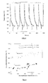
- the maximum temperature reached in the HTCS ® 130 was around 50oC lower than this reached in the 1.2343 side.
- the sudden rise of the die surface temperature corresponds of the in-cavity filling stage and hence the first instant of contact between molten alloy and in-cavity die surface.
- the drop of the surface temperature corresponds to the solidification of the molten alloy inside the die and establishing the heat transfer regime from the molten alloy to the die mass.
- the trigger and increase of the temperature at the different positions below the die surface signals the diffusion of heat trough the die mass towards the cooling channels.
- the maximum die in-cavity temperature reached at HTCS®130 side is 50oC lower than this reached in 1.2343 side.
- Figure 6 shows the trigger of the temperature obtained at the above mentioned positions below the die surface at the first instant of a casting cycle.
- the figure show that the trigger of the temperature at 1 mm happens almost at the same time for both steels, at 10mm and 20mm, the trigger of the temperature happens 70% and 57% earlier for the HTCS ® material with thermal conductivity around 57 W/m.K at RT compared to the H11 with thermal conductivity around 26 W/m.K at room temperature
- the example deals with the application of the invented systems on gravity die casting or permanent mould casting.
- This example represents also the situation of Low Pressure Die Casting (LPDC) and Counter Pressure Die Casting (CPDC) as the die surface is usually coated with relatively thick coating to act as a thermal barrier in addition to the realising role when casting with the same.
- LPDC Low Pressure Die Casting
- CPDC Counter Pressure Die Casting
- the molten alloy is poured in to the die in-cavity either under gravity (case of permanent or gravity die casting) or under a very slow velocity (case of Low Pressure and Counter Pressure Die casting).
- two identical gravity dies have been constructed respectively of 1.2343 hot work tool steel and High Thermal Conductivity HTCS ® 130 hot work tool steel.
- the in-cavity was designed to produce a piece with the dimension 100 x 100 x 10 mm.
- the alloy cast was A380 (Al-9Si-3Cu) aluminium alloy No internal and external cooling is used in the experiments.
- a temperature sensor was introduced in the each of both dies, in the same place at cavity centre to measure the die temperature at 1mm, 10 mm and 20 mm below the cavity surface.
- the temperature of the molten A380 alloy has been measured by open thermocouples that have been introduced into about 1 mm depth in the in-cavity in the same position, at the die in-cavity centre for both die.
- the aluminium liquid makes the junction between the opened wires of the thermocouple and the temperature of the alloy is measured precisely.
- a semi-permanent silicate based coating has been applied onto the die cavity surface by the conventional spraying method under 2 bar of pressure. Prior to the application of the coating, the dies have been preheated to around 130-15oC. Several trials have been carryout on the two dies.
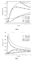
- Figure 10 show the temperatures measured for a representative cycle, produced in the same conditions. From the curves of A380 alloy, marked as 1.2343_Al and HTCS_Al respectively for 1.2343 and HTCS ® 130 dies, on can observe that in the case of HTCS-coated die, the alloy temperature drops to below its solidus points (around 539 oC) after about 47s of solidification time meanwhile the alloy temperature drops to below its solidus after about 63 s of solidification time. This means the solidification time is decreased by around 34% which is very considerable in productivity point of view. This means also a higher solidification rate by about 34% which has resulted in a finer microstructure of the produced part.
- the die temperature at 1mm below the in-cavity die surface, reaches to its maximum 325 oC after around 10 seconds of solidifications however in the case of 1.2343 the maximum temperature of the die is much higher (about 375 oC) and reached after 18 seconds of solidification.
- the equilibrium temperature used during the tests 200 oC
- the cooling channels can be designed to be at least 30% more closer to the in-cavity die surface in the case of HTCS ® 130 die compared to the conventional 1.2343 die.
- Example 3 Sol gel coating.
- the effectiveness of the sol-gel technology to deposit semi-permanent coatings in the in-cavity die surface capable of replacing the release effect of the lubricant was studied.
- Three high thermal conductivity steel pieces were prepared. One was left uncoated. The other was coated with an inorganic coating containing Al 2 O 3 and SiO 4 , finally a third piece was coated with a sol-gel coating containing TiO 2 nano-particles, an inorganic/organic matrix and some aluminium and magnesium pigments was applied on the third piece. The third piece was heated on an oxidizing environment and quenched. In this way some cracks were generated on the coating to test its effectiveness in a worn out state.
Landscapes
- Engineering & Computer Science (AREA)
- Chemical & Material Sciences (AREA)
- Mechanical Engineering (AREA)
- Materials Engineering (AREA)
- Manufacturing & Machinery (AREA)
- Inorganic Chemistry (AREA)
- Life Sciences & Earth Sciences (AREA)
- Wood Science & Technology (AREA)
- Organic Chemistry (AREA)
- Molds, Cores, And Manufacturing Methods Thereof (AREA)
- Forging (AREA)
Priority Applications (3)
| Application Number | Priority Date | Filing Date | Title |
|---|---|---|---|
| EP12382281.9A EP2684627A1 (fr) | 2012-07-13 | 2012-07-13 | Procédé de formation de matériau dans un état préchauffé ou fondu afin de réduire fortement le coût de production des pièces produites |
| EP13741707.7A EP2872273A1 (fr) | 2012-07-13 | 2013-07-19 | Procédé pour processus de formage de matériau à l'état préchauffé ou fondu permettant de réduire fortement le coût de production des pièces produites |
| PCT/EP2013/065275 WO2014009571A1 (fr) | 2012-07-13 | 2013-07-19 | Procédé pour processus de formage de matériau à l'état préchauffé ou fondu permettant de réduire fortement le coût de production des pièces produites |
Applications Claiming Priority (1)
| Application Number | Priority Date | Filing Date | Title |
|---|---|---|---|
| EP12382281.9A EP2684627A1 (fr) | 2012-07-13 | 2012-07-13 | Procédé de formation de matériau dans un état préchauffé ou fondu afin de réduire fortement le coût de production des pièces produites |
Publications (1)
| Publication Number | Publication Date |
|---|---|
| EP2684627A1 true EP2684627A1 (fr) | 2014-01-15 |
Family
ID=48875012
Family Applications (2)
| Application Number | Title | Priority Date | Filing Date |
|---|---|---|---|
| EP12382281.9A Withdrawn EP2684627A1 (fr) | 2012-07-13 | 2012-07-13 | Procédé de formation de matériau dans un état préchauffé ou fondu afin de réduire fortement le coût de production des pièces produites |
| EP13741707.7A Withdrawn EP2872273A1 (fr) | 2012-07-13 | 2013-07-19 | Procédé pour processus de formage de matériau à l'état préchauffé ou fondu permettant de réduire fortement le coût de production des pièces produites |
Family Applications After (1)
| Application Number | Title | Priority Date | Filing Date |
|---|---|---|---|
| EP13741707.7A Withdrawn EP2872273A1 (fr) | 2012-07-13 | 2013-07-19 | Procédé pour processus de formage de matériau à l'état préchauffé ou fondu permettant de réduire fortement le coût de production des pièces produites |
Country Status (2)
| Country | Link |
|---|---|
| EP (2) | EP2684627A1 (fr) |
| WO (1) | WO2014009571A1 (fr) |
Cited By (3)
| Publication number | Priority date | Publication date | Assignee | Title |
|---|---|---|---|---|
| WO2016084209A1 (fr) * | 2014-11-27 | 2016-06-02 | 株式会社日立製作所 | Dispositif d'évaluation et procédé d'évaluation de procédé de forgeage à chaud et procédé de fabrication d'un produit forgé |
| KR101842555B1 (ko) | 2015-12-09 | 2018-03-27 | 주식회사 포스코 | 도금 강판의 표면처리용 조성물, 이를 이용하여 표면처리된 강판, 및 이를 이용한 표면처리 방법 |
| CN113857281A (zh) * | 2021-11-22 | 2021-12-31 | 成都先进金属材料产业技术研究院股份有限公司 | 高温合金棒冷拉拔用涂料润滑剂及其制备和使用方法 |
Families Citing this family (1)
| Publication number | Priority date | Publication date | Assignee | Title |
|---|---|---|---|---|
| CN105824132B (zh) * | 2016-06-02 | 2019-03-01 | 江西昌洲光学科技有限公司 | 金属眼镜框架无焊接压铸一次性成型模具及其成型工艺 |
Citations (9)
| Publication number | Priority date | Publication date | Assignee | Title |
|---|---|---|---|---|
| JPH0753980A (ja) | 1993-08-17 | 1995-02-28 | Risuron:Kk | ダイカスト用粉末離型剤 |
| JPH0966340A (ja) | 1995-08-31 | 1997-03-11 | Nippon Kokuen Kogyo Kk | スクイズキャスティング用離型剤原料 |
| DE19834966A1 (de) | 1998-08-03 | 2000-02-17 | Fraunhofer Ges Forschung | Anti-Haft-Beschichtung für Druckgußwerkzeuge |
| EP1236525A2 (fr) * | 2001-02-15 | 2002-09-04 | Alcan Technology & Management AG | Moule de coulée |
| DE10224206A1 (de) * | 2001-06-01 | 2002-12-12 | Ngk Insulators Ltd | Spritzgussform für eine halbverfestigte FE-Legierung |
| US7056395B1 (en) * | 1999-09-01 | 2006-06-06 | Brush Wellman, Inc. | Dies for die casting aluminum and other metals |
| US20070054057A1 (en) * | 2003-06-13 | 2007-03-08 | Esk Ceramics Gmbh & Co. Kg | Durable bn mould separating agents for the die casting of non-ferrous metals |
| EP1818119A1 (fr) | 2004-08-31 | 2007-08-15 | Aoki Science Institute Co, Ltd | Agent de démoulage pour coulée sous pression à l'huile, procédé de réglage d'un rapport de mélange de solvant, procédé de coulée et dispositif de pulvérisation |
| EP2078953A2 (fr) | 2008-01-08 | 2009-07-15 | General Electric Company | Système et procédé de détection et d'analyse de compositions |
Family Cites Families (1)
| Publication number | Priority date | Publication date | Assignee | Title |
|---|---|---|---|---|
| EP1887096A1 (fr) | 2006-08-09 | 2008-02-13 | Rovalma, S.A. | Acier pour travail à chaud |
-
2012
- 2012-07-13 EP EP12382281.9A patent/EP2684627A1/fr not_active Withdrawn
-
2013
- 2013-07-19 WO PCT/EP2013/065275 patent/WO2014009571A1/fr active Application Filing
- 2013-07-19 EP EP13741707.7A patent/EP2872273A1/fr not_active Withdrawn
Patent Citations (9)
| Publication number | Priority date | Publication date | Assignee | Title |
|---|---|---|---|---|
| JPH0753980A (ja) | 1993-08-17 | 1995-02-28 | Risuron:Kk | ダイカスト用粉末離型剤 |
| JPH0966340A (ja) | 1995-08-31 | 1997-03-11 | Nippon Kokuen Kogyo Kk | スクイズキャスティング用離型剤原料 |
| DE19834966A1 (de) | 1998-08-03 | 2000-02-17 | Fraunhofer Ges Forschung | Anti-Haft-Beschichtung für Druckgußwerkzeuge |
| US7056395B1 (en) * | 1999-09-01 | 2006-06-06 | Brush Wellman, Inc. | Dies for die casting aluminum and other metals |
| EP1236525A2 (fr) * | 2001-02-15 | 2002-09-04 | Alcan Technology & Management AG | Moule de coulée |
| DE10224206A1 (de) * | 2001-06-01 | 2002-12-12 | Ngk Insulators Ltd | Spritzgussform für eine halbverfestigte FE-Legierung |
| US20070054057A1 (en) * | 2003-06-13 | 2007-03-08 | Esk Ceramics Gmbh & Co. Kg | Durable bn mould separating agents for the die casting of non-ferrous metals |
| EP1818119A1 (fr) | 2004-08-31 | 2007-08-15 | Aoki Science Institute Co, Ltd | Agent de démoulage pour coulée sous pression à l'huile, procédé de réglage d'un rapport de mélange de solvant, procédé de coulée et dispositif de pulvérisation |
| EP2078953A2 (fr) | 2008-01-08 | 2009-07-15 | General Electric Company | Système et procédé de détection et d'analyse de compositions |
Non-Patent Citations (1)
| Title |
|---|
| EBNER, R.; MARSONER S.; SILLER I.; ECKER W.: "Thermal Fatigue Behaviour of Hot Work Tool Steels - Heat Check Nucleation and Growth", 7TH INTERNATIONAL CONFERENCE ON TOOLING, vol. 1, 2006, pages 161 - 174 |
Cited By (5)
| Publication number | Priority date | Publication date | Assignee | Title |
|---|---|---|---|---|
| WO2016084209A1 (fr) * | 2014-11-27 | 2016-06-02 | 株式会社日立製作所 | Dispositif d'évaluation et procédé d'évaluation de procédé de forgeage à chaud et procédé de fabrication d'un produit forgé |
| JPWO2016084209A1 (ja) * | 2014-11-27 | 2017-04-27 | 株式会社日立製作所 | 熱間鍛造プロセス評価装置および評価方法、並びに鍛造品の製造方法 |
| KR101842555B1 (ko) | 2015-12-09 | 2018-03-27 | 주식회사 포스코 | 도금 강판의 표면처리용 조성물, 이를 이용하여 표면처리된 강판, 및 이를 이용한 표면처리 방법 |
| CN113857281A (zh) * | 2021-11-22 | 2021-12-31 | 成都先进金属材料产业技术研究院股份有限公司 | 高温合金棒冷拉拔用涂料润滑剂及其制备和使用方法 |
| CN113857281B (zh) * | 2021-11-22 | 2023-10-27 | 成都先进金属材料产业技术研究院股份有限公司 | 高温合金棒冷拉拔用涂料润滑剂及其制备和使用方法 |
Also Published As
| Publication number | Publication date |
|---|---|
| WO2014009571A8 (fr) | 2014-08-21 |
| EP2872273A1 (fr) | 2015-05-20 |
| WO2014009571A1 (fr) | 2014-01-16 |
Similar Documents
| Publication | Publication Date | Title |
|---|---|---|
| KR100942210B1 (ko) | 비철 금속의 주조에 사용하기 위한 이형제 층 | |
| Tjong et al. | Wear behaviour of an Al–12% Si alloy reinforced with a low volume fraction of SiC particles | |
| Chen | Formation and progression of die soldering during high pressure die casting | |
| CN101456069B (zh) | 一种双金属复合锤头的制造方法及锤柄预制件 | |
| EP2684627A1 (fr) | Procédé de formation de matériau dans un état préchauffé ou fondu afin de réduire fortement le coût de production des pièces produites | |
| EP2301689B1 (fr) | Procédé de coulage d'un alliage à base de fer dans un état semi-fondu ou semi-durci et moule pour le coulage | |
| Singh et al. | Synthesis of copper metal matrix hybrid composites using stir casting technique and its mechanical, optical and electrical behaviours | |
| Durrant et al. | Squeeze cast aluminium reinforced with mild steel inserts | |
| Singh et al. | Fabricating in situ powdered nickel–alumina metal matrix composites through microwave heating process: A sustainable approach | |
| US5996679A (en) | Apparatus for semi-solid processing of a metal | |
| Kovačević et al. | Industrial evaluation of duplex PVD hard coatings for HPDC | |
| Mohandas et al. | Studies on mechanical behaviour of aluminium/nickel coated silicon carbide reinforced functionally graded composite | |
| JP4779025B2 (ja) | 非鉄金属鋳造用離型層 | |
| Pastirčák | Effect of technological parameters on the AlSi12 alloy microstructure during crystallization under pressure | |
| JP4864426B2 (ja) | 鉄系合金の半溶融・半凝固鋳造用の金型 | |
| Gupta et al. | Metal matrix nanocomposites and their application in corrosion control | |
| Usef et al. | Influence of carbon nanotube reinforcement on the heat transfer coefficient, microstructure, and mechanical properties of a die cast Al-7Si-0.35 Mg alloy | |
| Pastirčák et al. | Effect of pressure on the crystallisation of AlSi7Mg alloy | |
| EP2744612B1 (fr) | Procédé de production de moulages à moules perdus | |
| Brezinová et al. | Analysis of tribodegradation factors limiting the life of the molds | |
| Sruthi et al. | Characterisation of SiC reinforced aluminium matrix composites for engine cylinder liner application | |
| TW200829350A (en) | Component of metal molding system | |
| Schilling et al. | Flow Length Influence of Cores Made of High-Temperature Composite in Semi-Solid AZ91 Produced in Thixomolding | |
| Ružbarský et al. | Spreading of cracks due to thermal fatigue in metal molds | |
| ŠČŮRY et al. | Effect of Technological Parameters on the Heat Transfer Coefficient in Alloy AlCu4Ti using Squeeze Casting Technology |
Legal Events
| Date | Code | Title | Description |
|---|---|---|---|
| PUAI | Public reference made under article 153(3) epc to a published international application that has entered the european phase |
Free format text: ORIGINAL CODE: 0009012 |
|
| AK | Designated contracting states |
Kind code of ref document: A1 Designated state(s): AL AT BE BG CH CY CZ DE DK EE ES FI FR GB GR HR HU IE IS IT LI LT LU LV MC MK MT NL NO PL PT RO RS SE SI SK SM TR |
|
| AX | Request for extension of the european patent |
Extension state: BA ME |
|
| STAA | Information on the status of an ep patent application or granted ep patent |
Free format text: STATUS: THE APPLICATION IS DEEMED TO BE WITHDRAWN |
|
| 18D | Application deemed to be withdrawn |
Effective date: 20140716 |