EP2684595A1 - Verfahren zur steuerung eines systems zur chemischen co2-absorption - Google Patents
Verfahren zur steuerung eines systems zur chemischen co2-absorption Download PDFInfo
- Publication number
- EP2684595A1 EP2684595A1 EP12747482.3A EP12747482A EP2684595A1 EP 2684595 A1 EP2684595 A1 EP 2684595A1 EP 12747482 A EP12747482 A EP 12747482A EP 2684595 A1 EP2684595 A1 EP 2684595A1
- Authority
- EP
- European Patent Office
- Prior art keywords
- absorbent
- amine
- amine absorbent
- inorganic alkali
- column
- Prior art date
- Legal status (The legal status is an assumption and is not a legal conclusion. Google has not performed a legal analysis and makes no representation as to the accuracy of the status listed.)
- Granted
Links
- 238000000034 method Methods 0.000 title claims abstract description 20
- 239000002250 absorbent Substances 0.000 claims abstract description 90
- 230000002745 absorbent Effects 0.000 claims abstract description 90
- XLYOFNOQVPJJNP-UHFFFAOYSA-N water Substances O XLYOFNOQVPJJNP-UHFFFAOYSA-N 0.000 claims abstract description 84
- 150000001412 amines Chemical class 0.000 claims abstract description 57
- 238000010521 absorption reaction Methods 0.000 claims abstract description 30
- 239000006096 absorbing agent Substances 0.000 claims abstract description 19
- 230000008929 regeneration Effects 0.000 claims abstract description 17
- 238000011069 regeneration method Methods 0.000 claims abstract description 17
- 150000003839 salts Chemical class 0.000 claims abstract description 17
- 239000000126 substance Substances 0.000 claims abstract description 16
- 238000001816 cooling Methods 0.000 claims abstract description 9
- 238000010438 heat treatment Methods 0.000 claims abstract description 9
- 238000004821 distillation Methods 0.000 claims abstract description 7
- 239000002904 solvent Substances 0.000 claims abstract description 5
- CURLTUGMZLYLDI-UHFFFAOYSA-N Carbon dioxide Chemical compound O=C=O CURLTUGMZLYLDI-UHFFFAOYSA-N 0.000 claims description 102
- 229910002092 carbon dioxide Inorganic materials 0.000 claims description 101
- 239000001569 carbon dioxide Substances 0.000 claims description 98
- 239000007789 gas Substances 0.000 claims description 44
- 239000007788 liquid Substances 0.000 claims description 19
- 229910001389 inorganic alkali salt Inorganic materials 0.000 claims description 17
- 239000000243 solution Substances 0.000 claims description 16
- 239000003513 alkali Substances 0.000 claims description 8
- 238000006477 desulfuration reaction Methods 0.000 claims description 7
- 230000023556 desulfurization Effects 0.000 claims description 7
- XTQHKBHJIVJGKJ-UHFFFAOYSA-N sulfur monoxide Chemical class S=O XTQHKBHJIVJGKJ-UHFFFAOYSA-N 0.000 claims description 7
- 238000002485 combustion reaction Methods 0.000 claims description 5
- 239000002803 fossil fuel Substances 0.000 claims description 4
- 229910052815 sulfur oxide Inorganic materials 0.000 claims description 3
- UGFAIRIUMAVXCW-UHFFFAOYSA-N Carbon monoxide Chemical compound [O+]#[C-] UGFAIRIUMAVXCW-UHFFFAOYSA-N 0.000 claims description 2
- 239000003546 flue gas Substances 0.000 claims description 2
- 238000011176 pooling Methods 0.000 claims description 2
- 238000005086 pumping Methods 0.000 claims description 2
- 239000012266 salt solution Substances 0.000 claims 8
- 239000000203 mixture Substances 0.000 claims 2
- 239000000654 additive Substances 0.000 claims 1
- 230000000996 additive effect Effects 0.000 claims 1
- 238000002156 mixing Methods 0.000 claims 1
- 159000000011 group IA salts Chemical class 0.000 abstract 1
- CDBYLPFSWZWCQE-UHFFFAOYSA-L Sodium Carbonate Chemical compound [Na+].[Na+].[O-]C([O-])=O CDBYLPFSWZWCQE-UHFFFAOYSA-L 0.000 description 38
- 238000005406 washing Methods 0.000 description 25
- 229910000029 sodium carbonate Inorganic materials 0.000 description 19
- 239000007921 spray Substances 0.000 description 12
- 239000007832 Na2SO4 Substances 0.000 description 6
- PMZURENOXWZQFD-UHFFFAOYSA-L Sodium Sulfate Chemical compound [Na+].[Na+].[O-]S([O-])(=O)=O PMZURENOXWZQFD-UHFFFAOYSA-L 0.000 description 6
- 229910052938 sodium sulfate Inorganic materials 0.000 description 6
- 238000011084 recovery Methods 0.000 description 5
- 239000002699 waste material Substances 0.000 description 5
- 238000010586 diagram Methods 0.000 description 4
- TXKMVPPZCYKFAC-UHFFFAOYSA-N disulfur monoxide Inorganic materials O=S=S TXKMVPPZCYKFAC-UHFFFAOYSA-N 0.000 description 4
- 239000003595 mist Substances 0.000 description 4
- 238000012544 monitoring process Methods 0.000 description 4
- 229920006395 saturated elastomer Polymers 0.000 description 4
- MWUXSHHQAYIFBG-UHFFFAOYSA-N Nitric oxide Chemical compound O=[N] MWUXSHHQAYIFBG-UHFFFAOYSA-N 0.000 description 3
- 239000002585 base Substances 0.000 description 3
- 230000001276 controlling effect Effects 0.000 description 3
- 239000000498 cooling water Substances 0.000 description 3
- 238000010248 power generation Methods 0.000 description 3
- 230000001105 regulatory effect Effects 0.000 description 3
- 238000006243 chemical reaction Methods 0.000 description 2
- 239000003245 coal Substances 0.000 description 2
- 239000012717 electrostatic precipitator Substances 0.000 description 2
- BWHMMNNQKKPAPP-UHFFFAOYSA-L potassium carbonate Chemical compound [K+].[K+].[O-]C([O-])=O BWHMMNNQKKPAPP-UHFFFAOYSA-L 0.000 description 2
- 230000002265 prevention Effects 0.000 description 2
- 239000007787 solid Substances 0.000 description 2
- 238000011144 upstream manufacturing Methods 0.000 description 2
- RAHZWNYVWXNFOC-UHFFFAOYSA-N Sulphur dioxide Chemical compound O=S=O RAHZWNYVWXNFOC-UHFFFAOYSA-N 0.000 description 1
- 238000003915 air pollution Methods 0.000 description 1
- -1 amine compound Chemical class 0.000 description 1
- 239000007864 aqueous solution Substances 0.000 description 1
- 230000001174 ascending effect Effects 0.000 description 1
- 238000009835 boiling Methods 0.000 description 1
- 230000006866 deterioration Effects 0.000 description 1
- 239000012718 dry electrostatic precipitator Substances 0.000 description 1
- 239000000428 dust Substances 0.000 description 1
- 238000005516 engineering process Methods 0.000 description 1
- 238000001704 evaporation Methods 0.000 description 1
- 239000000446 fuel Substances 0.000 description 1
- 239000000295 fuel oil Substances 0.000 description 1
- 230000002427 irreversible effect Effects 0.000 description 1
- 229910000027 potassium carbonate Inorganic materials 0.000 description 1
- 239000000843 powder Substances 0.000 description 1
- 238000000197 pyrolysis Methods 0.000 description 1
- 230000009257 reactivity Effects 0.000 description 1
- 238000005070 sampling Methods 0.000 description 1
- 238000000926 separation method Methods 0.000 description 1
- 239000011734 sodium Substances 0.000 description 1
- 239000004071 soot Substances 0.000 description 1
- 150000003467 sulfuric acid derivatives Chemical class 0.000 description 1
- 238000010792 warming Methods 0.000 description 1
Images


Classifications
-
- B—PERFORMING OPERATIONS; TRANSPORTING
- B01—PHYSICAL OR CHEMICAL PROCESSES OR APPARATUS IN GENERAL
- B01D—SEPARATION
- B01D53/00—Separation of gases or vapours; Recovering vapours of volatile solvents from gases; Chemical or biological purification of waste gases, e.g. engine exhaust gases, smoke, fumes, flue gases, aerosols
- B01D53/34—Chemical or biological purification of waste gases
- B01D53/46—Removing components of defined structure
- B01D53/62—Carbon oxides
-
- B—PERFORMING OPERATIONS; TRANSPORTING
- B01—PHYSICAL OR CHEMICAL PROCESSES OR APPARATUS IN GENERAL
- B01D—SEPARATION
- B01D53/00—Separation of gases or vapours; Recovering vapours of volatile solvents from gases; Chemical or biological purification of waste gases, e.g. engine exhaust gases, smoke, fumes, flue gases, aerosols
- B01D53/14—Separation of gases or vapours; Recovering vapours of volatile solvents from gases; Chemical or biological purification of waste gases, e.g. engine exhaust gases, smoke, fumes, flue gases, aerosols by absorption
- B01D53/1425—Regeneration of liquid absorbents
-
- B—PERFORMING OPERATIONS; TRANSPORTING
- B01—PHYSICAL OR CHEMICAL PROCESSES OR APPARATUS IN GENERAL
- B01D—SEPARATION
- B01D53/00—Separation of gases or vapours; Recovering vapours of volatile solvents from gases; Chemical or biological purification of waste gases, e.g. engine exhaust gases, smoke, fumes, flue gases, aerosols
- B01D53/14—Separation of gases or vapours; Recovering vapours of volatile solvents from gases; Chemical or biological purification of waste gases, e.g. engine exhaust gases, smoke, fumes, flue gases, aerosols by absorption
- B01D53/1456—Removing acid components
- B01D53/1475—Removing carbon dioxide
-
- B—PERFORMING OPERATIONS; TRANSPORTING
- B01—PHYSICAL OR CHEMICAL PROCESSES OR APPARATUS IN GENERAL
- B01D—SEPARATION
- B01D2257/00—Components to be removed
- B01D2257/80—Water
-
- B—PERFORMING OPERATIONS; TRANSPORTING
- B01—PHYSICAL OR CHEMICAL PROCESSES OR APPARATUS IN GENERAL
- B01D—SEPARATION
- B01D53/00—Separation of gases or vapours; Recovering vapours of volatile solvents from gases; Chemical or biological purification of waste gases, e.g. engine exhaust gases, smoke, fumes, flue gases, aerosols
- B01D53/002—Separation of gases or vapours; Recovering vapours of volatile solvents from gases; Chemical or biological purification of waste gases, e.g. engine exhaust gases, smoke, fumes, flue gases, aerosols by condensation
-
- Y—GENERAL TAGGING OF NEW TECHNOLOGICAL DEVELOPMENTS; GENERAL TAGGING OF CROSS-SECTIONAL TECHNOLOGIES SPANNING OVER SEVERAL SECTIONS OF THE IPC; TECHNICAL SUBJECTS COVERED BY FORMER USPC CROSS-REFERENCE ART COLLECTIONS [XRACs] AND DIGESTS
- Y02—TECHNOLOGIES OR APPLICATIONS FOR MITIGATION OR ADAPTATION AGAINST CLIMATE CHANGE
- Y02A—TECHNOLOGIES FOR ADAPTATION TO CLIMATE CHANGE
- Y02A50/00—TECHNOLOGIES FOR ADAPTATION TO CLIMATE CHANGE in human health protection, e.g. against extreme weather
- Y02A50/20—Air quality improvement or preservation, e.g. vehicle emission control or emission reduction by using catalytic converters
-
- Y—GENERAL TAGGING OF NEW TECHNOLOGICAL DEVELOPMENTS; GENERAL TAGGING OF CROSS-SECTIONAL TECHNOLOGIES SPANNING OVER SEVERAL SECTIONS OF THE IPC; TECHNICAL SUBJECTS COVERED BY FORMER USPC CROSS-REFERENCE ART COLLECTIONS [XRACs] AND DIGESTS
- Y02—TECHNOLOGIES OR APPLICATIONS FOR MITIGATION OR ADAPTATION AGAINST CLIMATE CHANGE
- Y02C—CAPTURE, STORAGE, SEQUESTRATION OR DISPOSAL OF GREENHOUSE GASES [GHG]
- Y02C20/00—Capture or disposal of greenhouse gases
- Y02C20/40—Capture or disposal of greenhouse gases of CO2
Definitions
- the present invention relates to a method of controlling a carbon dioxide (CO 2 ) chemical absorption system.
- the prevent invention relates to a method of controlling a carbon dioxide (CO 2 ) chemical absorption system comprising a distillation reclaimer, the method allowing the system to be operated with minimum makeup water while maintaining a water balance in CO 2 recovery equipment.
- Fig. 3 shows an embodiment of a power generation plant comprising a conventional CO 2 chemical absorption system.
- the power generation plant mainly comprises Boiler 1, Denitration Device 2, Air Heater 3, Electrostatic Precipitator 4, Wet Desulfurization Device 5, Pre-scrubber 10, CO 2 Absorber Column 20, Desorber Column 40, Reboiler 60 and the like.
- Combustion exhaust gas generated by combustion of fossil fuels such as coal and discharged from Boiler 1 is passed through Denitration Device 2 to remove nitrogen oxide, and then passed through Air Heater 3 for heat exchange and cooled down to, for example, 120 °C to 170 °C.
- the exhaust gas passed through Air Heater 3 is passed through Electrostatic Precipitator 4 to remove soot dust in the exhaust gas, and further pressurized by an induced draft fan, and then subjected to Wet Desulfurization Device 5 to remove sulfur oxide (SO 2 ). About 10 ppm of SO 2 usually remains in the outlet gas from Wet Desulfurization Device 5.
- Pre-scrubber 10 is provided as a pretreatment device for CO 2 chemical absorption equipment to reduce the amount of residual SO 2 as much as possible at this stage (for example, 1 ppm or less).
- CO 2 Absorber Column 20 comprises Packed Bed 21, which is a main CO 2 absorbing section, Absorbent Spray Section 22, Water Washing Section 24, Washing Water Spray Section 25, Demister 26, Washing Water Reservoir 27, Condenser 28 and Washing Water Pump 29.
- CO 2 contained in exhaust gas is absorbed into CO 2 absorbent in Packed Bed 21 by gas-liquid contacts with CO 2 absorbent supplied from a CO 2 absorbent spray section located at the upper part of CO 2 Absorber Column 20.
- Water Washing Section 24 De-CO 2 Gas 23 heated by the exothermic reaction of absorption is cooled, and mist coming along with the gas is removed. Further, washing water cooled by Condenser 28 is recirculated for use through Washing Water Pump 29. After removing mist coming along with the gas by Demister 26 provided above Water Washing Section 24, the gas is discharged out of the system as Treated Gas 37 (de-CO 2 gas).
- the CO 2 absorbed absorbent is withdrawn from a liquid reservoir provided at the lower part of Absorber Column 20 with Absorber Column Withdrawal Pump 33, heated by Heat Exchanger 34 and then passed to Desorber Column 40.
- Desorber Column 40 the CO 2 enriched absorbent which is sprayed from Spray Section 42 is fed to Packed Bed 41. Meanwhile, vapor is supplied to the bottom of Desorber Column 40 from Reboiler 60 via Vapor Supply Line 65.
- Packed Bed 41 the CO 2 enriched absorbent makes gas-liquid contacts with vapor coming up from the bottom to degas CO 2 in the absorbent to the gas phase. Mist of some absorbent coming along with the degassed CO 2 gas is removed with Water Washing Section 43.
- Demister 45 provided above Water Washing Section 43 removes the mist coming along with the gas from Water Washing Section 43 and the like, and then the gas is discharged from the top of Desorber Column 40 as CO 2 Gas 46. Then, the CO 2 gas is cooled down to about 40°C in Condenser 47, and then separated into gas and condensed water in CO 2 Separator 48. The separated CO 2 gas is introduced to CO 2 Liquefying Device (not shown) while the condensed water is supplied to Water Spray Section 44 in Desorber Column 40 through Line 49 by Drain Pump 50.
- the CO 2 absorbent from which CO 2 is degassed is pooled in Desorber Column Liquid Reservoir 51, and then passed to Reboiler 60 through Reboiler Liquid Feeding Line 52.
- a heat exchanger tube and the like is provided inside Reboiler 60, in which vapor is generated by indirectly heating the CO 2 absorbent with steam 62 supplied through a steam supply line. The vapor is then supplied to the desorber column through Vapor Supply Line 65. Steam 62 used in Reboiler 60 is returned to drain water in the heat exchanger tube, and collected.
- the CO 2 absorbent pooled in the liquid reservoir at the bottom of Desorber Column 40 is passed through Desorber Column Withdrawal Line 66 to Heat Exchanger 34 and Condenser 29 for cooling, and then returned to the CO 2 absorber column.
- HSS heat stable salts
- Reclaimer 94 Some of absorbent in which heat stable salts are accumulated to some extent is withdrawn to Reclaimer 94 where inorganic alkali salts such as sodium carbonate (Na 2 CO 3 ), potassium carbonate and the like are added through an inorganic alkali salt addition line to remove heat stable salts from absorbent as corresponding sulfates.
- Reclaimer 94 is operated as follows. First, the operation of CO 2 Absorber Equipment 20 is stopped. The CO 2 absorbent from which CO 2 is degassed is fed to Reclaimer 94 via Flowmeter 92 and Cutoff Valve 91. The flowmeter monitors an amount of liquid introduced to Reclaimer 94 with Pump 93.
- the CO 2 absorbent is monitored for a water level with Level Transmitter 95 provided in Reclaimer 94, and fed until fully filled. Upon filled to the full capacity, Cutoff Valve 91 is closed. By pre-feeding a Na based alkali solution such as Na 2 CO 3 in Reclaimer 94, HSS in an amine solution reacts with the alkali solution, i.e., S attached to amine dissociates to give Na 2 SO 4 . Next, by opening Cutoff Valve 98 to supply high temperature steam via Steam Supply Line 96, the CO 2 absorbent is allowed to be boiled and evaporated.
- a Na based alkali solution such as Na 2 CO 3 in Reclaimer 94
- HSS in an amine solution reacts with the alkali solution, i.e., S attached to amine dissociates to give Na 2 SO 4 .
- Cutoff Valve 98 to supply high temperature steam via Steam Supply Line 96, the CO 2 absorbent is allowed to be boiled and evaporated.
- the temperature of the steam supplied to Reclaimer 94 through Steam Supply Line 96 is usually higher than that used in Reboiler 60 in order to separate amine from Na 2 SO 4 by boiling and evaporating amine.
- the temperature of the steam for Reboiler 60 is selected in order to avoid pyrolysis of amine.
- the evaporated CO 2 absorbent is returned to Desorber Column 40 through Amine Vapor Line 97.
- the amine absorbent ascending along Desorber Column 40 is cooled in Water Washing Section 43, and further cooled down to about 40°C in Condenser 47 to be liquefied. Then it is returned to Desorber Column 40 after passed through CO 2 Separator 48 and Drain Pump 50.
- Reclaimer 94 Na 2 SO 4 is gradually concentrated while amine and the like is evaporated.
- the steam supply to Reclaimer 94 is stopped.
- Cutoff Valve 98 is closed, and Cutoff Valve 100 provided at Amine Waste Line 99 is opened to discharge amine waste containing Na 2 SO 4 to Amine Waste Tank 101.
- a base such Na 2 CO 3 is introduced, and amine and Na 2 SO 4 are separated. Na 2 SO 4 is discharged out of the system while amine absorbent is returned to the absorber column.
- quantitative feeding of Na 2 CO 3 and the like is difficult from an engineering standpoint because Na 2 CO 3 is in a form of powder. Therefore, Na 2 CO 3 is first dissolved in water in a buffer tank and the like, and then introduced to the system as an aqueous solution.
- inlet gas is usually saturated at 40°C while outlet gas from the absorber column and the desorber column is also saturated at the same temperature of 40°C. Therefore, almost no additional water is supplied.
- a processing speed of a reclaimer is usually less than 1% of the amine circulation volume to circulate. In the case that the volume is set to 0.5% and a concentration of HSS in a system is 2 wt%, about 10 kg/h of Na 2 CO 3 is required. To dissolve this amount of Na 2 CO 3 in water, about 3 times of that weight, i.e. 30 kg/h of water is required. Adding more makeup water to the system is difficult in view of amine supply and prevention of amine concentration in washing water used for Water Washing Section 24.
- inlet gas is saturated at 40°C while outlet gas from the absorber column and the desorber column is also saturated at the same temperature of 40°C. Therefore, a problem is that almost no makeup water can be supplied. Further, another problem is that adding more makeup water to the system is difficult in view of amine supply and prevention of amine concentration in washing water used for Water Washing Section 24. Therefore, there have been the following problems.
- a water balance in CO 2 absorption equipment has to be disregarded.
- temperature of outlet gas has to be changed to increase an amount of released water. Changing a water balance and reducing a concentration of amine is not preferable because excess water needs to be heated in a desorber column and an increased amount of steam 62 is required, resulting in an increased utility cost.
- An object of the present invention is to solve a problem of a water balance associated with operation of a reclaimer in a CO 2 absorption system having the conventional reclaimer to minimize water supply from the outside of the system so that the CO 2 absorption system is kept in optimal conditions.
- the above object is achieved by rerouting condensed water separated in CO 2 Separator 48 to Adjustment Tank 83 via Drain Line 49 and Drain Pump 50 to pool some of drain water which is otherwise returned to Desorber Column 40 via Water Washing Spray Section 44; adjusting a liquid level in Adjustment Tank 83 with Flow Regulating Valve 81; introducing a solid base such as Na 2 CO 3 through Feeder 84 having weight monitoring capability to adjust a concentration of a Na 2 CO 3 solution; and feeding an appropriate amount of the Na 2 CO 3 solution depending on an amount of HSS in absorbent to Reclaimer 94 or Amine Supply Line 102 upstream of Reclaimer 94.
- a solid base such as Na 2 CO 3
- Feeder 84 having weight monitoring capability to adjust a concentration of a Na 2 CO 3 solution
- feeding an appropriate amount of the Na 2 CO 3 solution depending on an amount of HSS in absorbent to Reclaimer 94 or Amine Supply Line 102 upstream of Reclaimer 94.
- a water balance in a system can be kept constant similarly as when a reclaimer is not operated because there is no water supply from the outside of the system.
- the water supply from the outside of the system is a factor responsible for a disturbed water balance. Therefore the CO 2 absorption system can be stably operated.
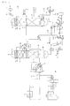
- Fig. 1 is an explanatory diagram of a CO 2 absorption system showing one Embodiment of the present invention.
- the present invention differs from the conventional system in Fig. 3 in that instead of supplying water from the outside, some of drain water separated in CO 2 separator 48 and present in Line 49 is pooled in Reservoir Tank 83 depending on a liquid level, and a solid base such as Na 2 CO 3 is introduced into Tank 83, and an appropriate amount of Na 2 CO 3 solution is supplied to Reclaimer 94 depending on an amount of HSS in absorbent.
- an appropriate amount of the Na 2 CO 3 solution is supplied to Reclaimer 94 through Feed Pump 85 while monitoring a feeding mount with Flowmeter 87 so that the amount of HHS is not higher than a predetermined level.
- Fig. 2 shows another Embodiment of the present invention in which a feeding position is different from that of Embodiment in Fig. 1 .
- the Na 2 CO 3 solution is fed to Amine Feeding Line 102 upstream of Reclaimer 94 instead of Reclaimer 94.
- the CO 2 absorption systems of Figs. 1 and 2 have solved the problem of a water balance associated with operation of the reclaimer in the conventional system shown in Fig. 3 . Even if there is no water supply from the outside of the system, the CO 2 absorption systems can be operated under optimal conditions.
Priority Applications (1)
| Application Number | Priority Date | Filing Date | Title |
|---|---|---|---|
| PL12747482T PL2684595T3 (pl) | 2011-02-14 | 2012-02-14 | Sposób kontrolowania układu absorpcji chemicznej CO2 i układ absorpcji chemicznej CO2 |
Applications Claiming Priority (2)
| Application Number | Priority Date | Filing Date | Title |
|---|---|---|---|
| JP2011028770A JP5636306B2 (ja) | 2011-02-14 | 2011-02-14 | Co2化学吸収システムの制御方法 |
| PCT/JP2012/053349 WO2012111648A1 (ja) | 2011-02-14 | 2012-02-14 | Co2化学吸収システムの制御方法 |
Publications (3)
| Publication Number | Publication Date |
|---|---|
| EP2684595A1 true EP2684595A1 (de) | 2014-01-15 |
| EP2684595A4 EP2684595A4 (de) | 2015-01-07 |
| EP2684595B1 EP2684595B1 (de) | 2018-03-21 |
Family
ID=46672567
Family Applications (1)
| Application Number | Title | Priority Date | Filing Date |
|---|---|---|---|
| EP12747482.3A Active EP2684595B1 (de) | 2011-02-14 | 2012-02-14 | Verfahren zur steuerung eines systems zur chemischen co2-absorption und system zur chemischen co2-absorption |
Country Status (7)
| Country | Link |
|---|---|
| US (1) | US20130315809A1 (de) |
| EP (1) | EP2684595B1 (de) |
| JP (1) | JP5636306B2 (de) |
| CA (1) | CA2826750C (de) |
| ES (1) | ES2671579T3 (de) |
| PL (1) | PL2684595T3 (de) |
| WO (1) | WO2012111648A1 (de) |
Families Citing this family (16)
| Publication number | Priority date | Publication date | Assignee | Title |
|---|---|---|---|---|
| KR101485953B1 (ko) * | 2013-03-20 | 2015-02-11 | 한국에너지기술연구원 | 양성자 주게 혼합물을 이용한 아민 흡수제의 재생방법 |
| JP6107443B2 (ja) | 2013-06-10 | 2017-04-05 | 株式会社Ihi | 不純物除去システム |
| US9192888B2 (en) | 2013-06-26 | 2015-11-24 | Uop Llc | Apparatuses and methods for removing acid gas from sour gas |
| JP6071838B2 (ja) * | 2013-10-18 | 2017-02-01 | 三菱重工業株式会社 | Co2又はh2s又はその双方の回収装置及び方法 |
| JP6392091B2 (ja) * | 2014-11-14 | 2018-09-19 | 株式会社東芝 | 二酸化炭素回収装置および二酸化炭素回収方法 |
| WO2016110965A1 (ja) * | 2015-01-07 | 2016-07-14 | 三菱日立パワーシステムズ株式会社 | ニトロソ化合物の処理方法および処理装置 |
| JP6345127B2 (ja) * | 2015-01-22 | 2018-06-20 | 三菱重工業株式会社 | 排ガス処理システム及び方法 |
| JP2016215174A (ja) * | 2015-05-26 | 2016-12-22 | 株式会社東芝 | 二酸化炭素回収システムおよび二酸化炭素回収システムの運転方法 |
| CN105251311A (zh) * | 2015-10-10 | 2016-01-20 | 江苏智道工程技术有限公司 | 回收多组分高浓度小流量间断有机废气有效成分的方法 |
| JP6598688B2 (ja) * | 2016-01-14 | 2019-10-30 | 三菱重工エンジニアリング株式会社 | 酸性ガス回収システム及びそれに用いるリクレーミング装置 |
| US11819777B2 (en) * | 2017-08-22 | 2023-11-21 | Saudi Arabian Oil Company | Systems and methods for enhancing amine agent recovery with a reclaimer |
| JP6987597B2 (ja) * | 2017-10-20 | 2022-01-05 | 三菱重工エンジニアリング株式会社 | リクレーミング装置及びリクレーミング方法 |
| JP6998174B2 (ja) * | 2017-10-20 | 2022-01-18 | 三菱重工エンジニアリング株式会社 | 酸性ガス除去装置及び酸性ガス除去方法 |
| US10625199B2 (en) | 2018-03-01 | 2020-04-21 | Mitsubishi Heavy Industries Engineering, Ltd. | CO2 recovery system and method of recovering CO2 |
| US11071942B2 (en) * | 2018-10-10 | 2021-07-27 | Mitsubishi Heavy Industries Engineering, Ltd. | Reclaiming apparatus and method, and CO2 recovery apparatus and method |
| CN113840803B (zh) * | 2019-05-28 | 2024-02-02 | 株式会社德山 | 二氧化碳气体及其它气体的回收方法 |
Citations (4)
| Publication number | Priority date | Publication date | Assignee | Title |
|---|---|---|---|---|
| US20060286017A1 (en) * | 2005-06-20 | 2006-12-21 | Cansolv Technologies Inc. | Waste gas treatment process including removal of mercury |
| WO2009104744A1 (ja) * | 2008-02-22 | 2009-08-27 | 三菱重工業株式会社 | Co2回収装置及びco2回収方法 |
| WO2010102877A1 (en) * | 2009-03-13 | 2010-09-16 | Aker Clean Carbon As | Method and plant for amine emission control |
| WO2010142716A1 (en) * | 2009-06-09 | 2010-12-16 | Aker Clean Carbon As | Method for reclaiming of co2 absorbent and a reclaimer |
Family Cites Families (5)
| Publication number | Priority date | Publication date | Assignee | Title |
|---|---|---|---|---|
| US5397556A (en) * | 1992-12-16 | 1995-03-14 | The Regents Of The Unviversity Of California | Process for recovery of sulfur from acid gases |
| JP3716195B2 (ja) * | 2001-08-21 | 2005-11-16 | 関西電力株式会社 | 脱硫脱炭酸方法 |
| US7056482B2 (en) * | 2003-06-12 | 2006-06-06 | Cansolv Technologies Inc. | Method for recovery of CO2 from gas streams |
| JP4699039B2 (ja) * | 2005-02-10 | 2011-06-08 | 関西電力株式会社 | 排気ガスの処理方法及び処理装置 |
| FR2942729B1 (fr) * | 2009-03-05 | 2011-08-19 | Inst Francais Du Petrole | Procede de desacidification d'un gaz par une solution absorbante, avec section de lavage a l'eau optimisee |
-
2011
- 2011-02-14 JP JP2011028770A patent/JP5636306B2/ja active Active
-
2012
- 2012-02-14 EP EP12747482.3A patent/EP2684595B1/de active Active
- 2012-02-14 US US13/984,539 patent/US20130315809A1/en not_active Abandoned
- 2012-02-14 ES ES12747482.3T patent/ES2671579T3/es active Active
- 2012-02-14 PL PL12747482T patent/PL2684595T3/pl unknown
- 2012-02-14 WO PCT/JP2012/053349 patent/WO2012111648A1/ja active Application Filing
- 2012-02-14 CA CA2826750A patent/CA2826750C/en active Active
Patent Citations (4)
| Publication number | Priority date | Publication date | Assignee | Title |
|---|---|---|---|---|
| US20060286017A1 (en) * | 2005-06-20 | 2006-12-21 | Cansolv Technologies Inc. | Waste gas treatment process including removal of mercury |
| WO2009104744A1 (ja) * | 2008-02-22 | 2009-08-27 | 三菱重工業株式会社 | Co2回収装置及びco2回収方法 |
| WO2010102877A1 (en) * | 2009-03-13 | 2010-09-16 | Aker Clean Carbon As | Method and plant for amine emission control |
| WO2010142716A1 (en) * | 2009-06-09 | 2010-12-16 | Aker Clean Carbon As | Method for reclaiming of co2 absorbent and a reclaimer |
Non-Patent Citations (1)
| Title |
|---|
| See also references of WO2012111648A1 * |
Also Published As
| Publication number | Publication date |
|---|---|
| CA2826750A1 (en) | 2012-08-23 |
| WO2012111648A1 (ja) | 2012-08-23 |
| EP2684595B1 (de) | 2018-03-21 |
| JP2012166139A (ja) | 2012-09-06 |
| ES2671579T3 (es) | 2018-06-07 |
| EP2684595A4 (de) | 2015-01-07 |
| JP5636306B2 (ja) | 2014-12-03 |
| US20130315809A1 (en) | 2013-11-28 |
| PL2684595T3 (pl) | 2018-08-31 |
| CA2826750C (en) | 2019-06-18 |
Similar Documents
| Publication | Publication Date | Title |
|---|---|---|
| CA2826750C (en) | Method of controlling co2 chemical absorption system | |
| Wang et al. | Current status and challenges of the ammonia escape inhibition technologies in ammonia-based CO2 capture process | |
| JP5507584B2 (ja) | アミン放出物制御のための方法およびプラント | |
| JP5859076B2 (ja) | アンモニアベースのco2吸収性溶液からの不揮発物の除去 | |
| US20130269525A1 (en) | Absorption Media for Scrubbing CO2 from a Gas Stream and Methods Using the Same | |
| EP2695662B1 (de) | Co2-rückgewinnungsvorrichtung und betriebssteuerverfahren für eine co2-rückgewinnungsvorrichtung | |
| EP2823876B1 (de) | System zur chemischen kohlendioxidabsorption in verbrennungsabgasen | |
| JP5762253B2 (ja) | Co2化学吸収システムの制御方法 | |
| US9463411B2 (en) | Carbon dioxide chemical absorption system installed with vapor recompression equipment | |
| CN111372671B (zh) | 气体处理方法及气体处理装置 | |
| WO2012067101A1 (ja) | 二酸化炭素化学吸収システムの制御方法および装置 | |
| JP2013059727A (ja) | Co2回収装置およびco2回収方法 | |
| KR20130010253A (ko) | 산성가스 포집을 위한 탈거장치의 에너지원 재사용 방법 | |
| JP2017124374A (ja) | 酸性ガス回収システム及びそれに用いるリクレーミング装置 | |
| JP5812847B2 (ja) | 二酸化炭素の回収装置及び方法 | |
| AU2015200530B2 (en) | Removal of non-volatiles from ammonia-based CO2-absorbent solution |
Legal Events
| Date | Code | Title | Description |
|---|---|---|---|
| PUAI | Public reference made under article 153(3) epc to a published international application that has entered the european phase |
Free format text: ORIGINAL CODE: 0009012 |
|
| 17P | Request for examination filed |
Effective date: 20130913 |
|
| AK | Designated contracting states |
Kind code of ref document: A1 Designated state(s): AL AT BE BG CH CY CZ DE DK EE ES FI FR GB GR HR HU IE IS IT LI LT LU LV MC MK MT NL NO PL PT RO RS SE SI SK SM TR |
|
| DAX | Request for extension of the european patent (deleted) | ||
| A4 | Supplementary search report drawn up and despatched |
Effective date: 20141208 |
|
| RIC1 | Information provided on ipc code assigned before grant |
Ipc: B01D 53/62 20060101AFI20141202BHEP Ipc: B01D 53/14 20060101ALI20141202BHEP Ipc: B01D 53/34 20060101ALI20141202BHEP Ipc: B01D 53/50 20060101ALI20141202BHEP Ipc: B01D 53/77 20060101ALI20141202BHEP Ipc: B01D 53/00 20060101ALI20141202BHEP |
|
| RAP1 | Party data changed (applicant data changed or rights of an application transferred) |
Owner name: MITSUBISHI HITACHI POWER SYSTEMS, LTD. |
|
| RIC1 | Information provided on ipc code assigned before grant |
Ipc: B01D 53/77 20060101ALI20150302BHEP Ipc: B01D 53/50 20060101ALI20150302BHEP Ipc: B01D 53/14 20060101ALI20150302BHEP Ipc: B01D 53/62 20060101AFI20150302BHEP Ipc: B01D 53/34 20060101ALI20150302BHEP Ipc: B01D 53/00 20060101ALI20150302BHEP |
|
| RAP1 | Party data changed (applicant data changed or rights of an application transferred) |
Owner name: MITSUBISHI HITACHI POWER SYSTEMS, LTD. |
|
| STAA | Information on the status of an ep patent application or granted ep patent |
Free format text: STATUS: EXAMINATION IS IN PROGRESS |
|
| 17Q | First examination report despatched |
Effective date: 20161206 |
|
| GRAP | Despatch of communication of intention to grant a patent |
Free format text: ORIGINAL CODE: EPIDOSNIGR1 |
|
| STAA | Information on the status of an ep patent application or granted ep patent |
Free format text: STATUS: GRANT OF PATENT IS INTENDED |
|
| INTG | Intention to grant announced |
Effective date: 20170927 |
|
| RIN1 | Information on inventor provided before grant (corrected) |
Inventor name: SHIMAMURA, JUN |
|
| GRAS | Grant fee paid |
Free format text: ORIGINAL CODE: EPIDOSNIGR3 |
|
| GRAA | (expected) grant |
Free format text: ORIGINAL CODE: 0009210 |
|
| STAA | Information on the status of an ep patent application or granted ep patent |
Free format text: STATUS: THE PATENT HAS BEEN GRANTED |
|
| AK | Designated contracting states |
Kind code of ref document: B1 Designated state(s): AL AT BE BG CH CY CZ DE DK EE ES FI FR GB GR HR HU IE IS IT LI LT LU LV MC MK MT NL NO PL PT RO RS SE SI SK SM TR |
|
| REG | Reference to a national code |
Ref country code: GB Ref legal event code: FG4D |
|
| REG | Reference to a national code |
Ref country code: CH Ref legal event code: EP |
|
| REG | Reference to a national code |
Ref country code: AT Ref legal event code: REF Ref document number: 980490 Country of ref document: AT Kind code of ref document: T Effective date: 20180415 |
|
| REG | Reference to a national code |
Ref country code: IE Ref legal event code: FG4D |
|
| REG | Reference to a national code |
Ref country code: DE Ref legal event code: R096 Ref document number: 602012044207 Country of ref document: DE |
|
| REG | Reference to a national code |
Ref country code: ES Ref legal event code: FG2A Ref document number: 2671579 Country of ref document: ES Kind code of ref document: T3 Effective date: 20180607 |
|
| REG | Reference to a national code |
Ref country code: SE Ref legal event code: TRGR |
|
| REG | Reference to a national code |
Ref country code: NL Ref legal event code: MP Effective date: 20180321 |
|
| PG25 | Lapsed in a contracting state [announced via postgrant information from national office to epo] |
Ref country code: FI Free format text: LAPSE BECAUSE OF FAILURE TO SUBMIT A TRANSLATION OF THE DESCRIPTION OR TO PAY THE FEE WITHIN THE PRESCRIBED TIME-LIMIT Effective date: 20180321 Ref country code: HR Free format text: LAPSE BECAUSE OF FAILURE TO SUBMIT A TRANSLATION OF THE DESCRIPTION OR TO PAY THE FEE WITHIN THE PRESCRIBED TIME-LIMIT Effective date: 20180321 Ref country code: LT Free format text: LAPSE BECAUSE OF FAILURE TO SUBMIT A TRANSLATION OF THE DESCRIPTION OR TO PAY THE FEE WITHIN THE PRESCRIBED TIME-LIMIT Effective date: 20180321 Ref country code: CY Free format text: LAPSE BECAUSE OF FAILURE TO SUBMIT A TRANSLATION OF THE DESCRIPTION OR TO PAY THE FEE WITHIN THE PRESCRIBED TIME-LIMIT Effective date: 20180321 |
|
| REG | Reference to a national code |
Ref country code: LT Ref legal event code: MG4D |
|
| REG | Reference to a national code |
Ref country code: AT Ref legal event code: MK05 Ref document number: 980490 Country of ref document: AT Kind code of ref document: T Effective date: 20180321 |
|
| REG | Reference to a national code |
Ref country code: NO Ref legal event code: T2 Effective date: 20180321 |
|
| PG25 | Lapsed in a contracting state [announced via postgrant information from national office to epo] |
Ref country code: BG Free format text: LAPSE BECAUSE OF FAILURE TO SUBMIT A TRANSLATION OF THE DESCRIPTION OR TO PAY THE FEE WITHIN THE PRESCRIBED TIME-LIMIT Effective date: 20180621 Ref country code: GR Free format text: LAPSE BECAUSE OF FAILURE TO SUBMIT A TRANSLATION OF THE DESCRIPTION OR TO PAY THE FEE WITHIN THE PRESCRIBED TIME-LIMIT Effective date: 20180622 Ref country code: LV Free format text: LAPSE BECAUSE OF FAILURE TO SUBMIT A TRANSLATION OF THE DESCRIPTION OR TO PAY THE FEE WITHIN THE PRESCRIBED TIME-LIMIT Effective date: 20180321 Ref country code: RS Free format text: LAPSE BECAUSE OF FAILURE TO SUBMIT A TRANSLATION OF THE DESCRIPTION OR TO PAY THE FEE WITHIN THE PRESCRIBED TIME-LIMIT Effective date: 20180321 |
|
| PG25 | Lapsed in a contracting state [announced via postgrant information from national office to epo] |
Ref country code: EE Free format text: LAPSE BECAUSE OF FAILURE TO SUBMIT A TRANSLATION OF THE DESCRIPTION OR TO PAY THE FEE WITHIN THE PRESCRIBED TIME-LIMIT Effective date: 20180321 Ref country code: AL Free format text: LAPSE BECAUSE OF FAILURE TO SUBMIT A TRANSLATION OF THE DESCRIPTION OR TO PAY THE FEE WITHIN THE PRESCRIBED TIME-LIMIT Effective date: 20180321 Ref country code: NL Free format text: LAPSE BECAUSE OF FAILURE TO SUBMIT A TRANSLATION OF THE DESCRIPTION OR TO PAY THE FEE WITHIN THE PRESCRIBED TIME-LIMIT Effective date: 20180321 Ref country code: RO Free format text: LAPSE BECAUSE OF FAILURE TO SUBMIT A TRANSLATION OF THE DESCRIPTION OR TO PAY THE FEE WITHIN THE PRESCRIBED TIME-LIMIT Effective date: 20180321 |
|
| PG25 | Lapsed in a contracting state [announced via postgrant information from national office to epo] |
Ref country code: CZ Free format text: LAPSE BECAUSE OF FAILURE TO SUBMIT A TRANSLATION OF THE DESCRIPTION OR TO PAY THE FEE WITHIN THE PRESCRIBED TIME-LIMIT Effective date: 20180321 Ref country code: SK Free format text: LAPSE BECAUSE OF FAILURE TO SUBMIT A TRANSLATION OF THE DESCRIPTION OR TO PAY THE FEE WITHIN THE PRESCRIBED TIME-LIMIT Effective date: 20180321 Ref country code: AT Free format text: LAPSE BECAUSE OF FAILURE TO SUBMIT A TRANSLATION OF THE DESCRIPTION OR TO PAY THE FEE WITHIN THE PRESCRIBED TIME-LIMIT Effective date: 20180321 Ref country code: SM Free format text: LAPSE BECAUSE OF FAILURE TO SUBMIT A TRANSLATION OF THE DESCRIPTION OR TO PAY THE FEE WITHIN THE PRESCRIBED TIME-LIMIT Effective date: 20180321 |
|
| PG25 | Lapsed in a contracting state [announced via postgrant information from national office to epo] |
Ref country code: PT Free format text: LAPSE BECAUSE OF FAILURE TO SUBMIT A TRANSLATION OF THE DESCRIPTION OR TO PAY THE FEE WITHIN THE PRESCRIBED TIME-LIMIT Effective date: 20180723 |
|
| REG | Reference to a national code |
Ref country code: DE Ref legal event code: R097 Ref document number: 602012044207 Country of ref document: DE |
|
| PLBE | No opposition filed within time limit |
Free format text: ORIGINAL CODE: 0009261 |
|
| STAA | Information on the status of an ep patent application or granted ep patent |
Free format text: STATUS: NO OPPOSITION FILED WITHIN TIME LIMIT |
|
| PG25 | Lapsed in a contracting state [announced via postgrant information from national office to epo] |
Ref country code: DK Free format text: LAPSE BECAUSE OF FAILURE TO SUBMIT A TRANSLATION OF THE DESCRIPTION OR TO PAY THE FEE WITHIN THE PRESCRIBED TIME-LIMIT Effective date: 20180321 |
|
| 26N | No opposition filed |
Effective date: 20190102 |
|
| PG25 | Lapsed in a contracting state [announced via postgrant information from national office to epo] |
Ref country code: IT Free format text: LAPSE BECAUSE OF FAILURE TO SUBMIT A TRANSLATION OF THE DESCRIPTION OR TO PAY THE FEE WITHIN THE PRESCRIBED TIME-LIMIT Effective date: 20180321 |
|
| PG25 | Lapsed in a contracting state [announced via postgrant information from national office to epo] |
Ref country code: SI Free format text: LAPSE BECAUSE OF FAILURE TO SUBMIT A TRANSLATION OF THE DESCRIPTION OR TO PAY THE FEE WITHIN THE PRESCRIBED TIME-LIMIT Effective date: 20180321 |
|
| REG | Reference to a national code |
Ref country code: CH Ref legal event code: PL |
|
| PG25 | Lapsed in a contracting state [announced via postgrant information from national office to epo] |
Ref country code: LU Free format text: LAPSE BECAUSE OF NON-PAYMENT OF DUE FEES Effective date: 20190214 Ref country code: MC Free format text: LAPSE BECAUSE OF FAILURE TO SUBMIT A TRANSLATION OF THE DESCRIPTION OR TO PAY THE FEE WITHIN THE PRESCRIBED TIME-LIMIT Effective date: 20180321 |
|
| REG | Reference to a national code |
Ref country code: BE Ref legal event code: MM Effective date: 20190228 |
|
| REG | Reference to a national code |
Ref country code: IE Ref legal event code: MM4A |
|
| PG25 | Lapsed in a contracting state [announced via postgrant information from national office to epo] |
Ref country code: LI Free format text: LAPSE BECAUSE OF NON-PAYMENT OF DUE FEES Effective date: 20190228 Ref country code: CH Free format text: LAPSE BECAUSE OF NON-PAYMENT OF DUE FEES Effective date: 20190228 |
|
| PG25 | Lapsed in a contracting state [announced via postgrant information from national office to epo] |
Ref country code: IE Free format text: LAPSE BECAUSE OF NON-PAYMENT OF DUE FEES Effective date: 20190214 |
|
| PG25 | Lapsed in a contracting state [announced via postgrant information from national office to epo] |
Ref country code: BE Free format text: LAPSE BECAUSE OF NON-PAYMENT OF DUE FEES Effective date: 20190228 |
|
| PG25 | Lapsed in a contracting state [announced via postgrant information from national office to epo] |
Ref country code: TR Free format text: LAPSE BECAUSE OF FAILURE TO SUBMIT A TRANSLATION OF THE DESCRIPTION OR TO PAY THE FEE WITHIN THE PRESCRIBED TIME-LIMIT Effective date: 20180321 |
|
| PG25 | Lapsed in a contracting state [announced via postgrant information from national office to epo] |
Ref country code: MT Free format text: LAPSE BECAUSE OF NON-PAYMENT OF DUE FEES Effective date: 20190214 |
|
| REG | Reference to a national code |
Ref country code: DE Ref legal event code: R082 Ref document number: 602012044207 Country of ref document: DE Representative=s name: PAGE, WHITE & FARRER GERMANY LLP, DE Ref country code: DE Ref legal event code: R081 Ref document number: 602012044207 Country of ref document: DE Owner name: MITSUBISHI POWER, LTD., JP Free format text: FORMER OWNER: MITSUBISHI HITACHI POWER SYSTEMS, LTD., YOKOHAMA-SHI, KANAGAWA, JP |
|
| REG | Reference to a national code |
Ref country code: NO Ref legal event code: CHAD Owner name: MITSUBISHI POWER, JP |
|
| REG | Reference to a national code |
Ref country code: ES Ref legal event code: PC2A Owner name: MITSUBISHI POWER, LTD. Effective date: 20210421 |
|
| PG25 | Lapsed in a contracting state [announced via postgrant information from national office to epo] |
Ref country code: IS Free format text: LAPSE BECAUSE OF FAILURE TO SUBMIT A TRANSLATION OF THE DESCRIPTION OR TO PAY THE FEE WITHIN THE PRESCRIBED TIME-LIMIT Effective date: 20180721 |
|
| PG25 | Lapsed in a contracting state [announced via postgrant information from national office to epo] |
Ref country code: HU Free format text: LAPSE BECAUSE OF FAILURE TO SUBMIT A TRANSLATION OF THE DESCRIPTION OR TO PAY THE FEE WITHIN THE PRESCRIBED TIME-LIMIT; INVALID AB INITIO Effective date: 20120214 |
|
| PGFP | Annual fee paid to national office [announced via postgrant information from national office to epo] |
Ref country code: FR Payment date: 20220118 Year of fee payment: 11 |
|
| PG25 | Lapsed in a contracting state [announced via postgrant information from national office to epo] |
Ref country code: MK Free format text: LAPSE BECAUSE OF FAILURE TO SUBMIT A TRANSLATION OF THE DESCRIPTION OR TO PAY THE FEE WITHIN THE PRESCRIBED TIME-LIMIT Effective date: 20180321 |
|
| PGFP | Annual fee paid to national office [announced via postgrant information from national office to epo] |
Ref country code: GB Payment date: 20221230 Year of fee payment: 12 |
|
| PGFP | Annual fee paid to national office [announced via postgrant information from national office to epo] |
Ref country code: PL Payment date: 20221229 Year of fee payment: 12 |
|
| PGFP | Annual fee paid to national office [announced via postgrant information from national office to epo] |
Ref country code: NO Payment date: 20230208 Year of fee payment: 12 Ref country code: ES Payment date: 20230310 Year of fee payment: 12 |
|
| PGFP | Annual fee paid to national office [announced via postgrant information from national office to epo] |
Ref country code: DE Payment date: 20221229 Year of fee payment: 12 |
|
| PGFP | Annual fee paid to national office [announced via postgrant information from national office to epo] |
Ref country code: SE Payment date: 20231228 Year of fee payment: 13 |
|
| PGFP | Annual fee paid to national office [announced via postgrant information from national office to epo] |
Ref country code: PL Payment date: 20231228 Year of fee payment: 13 |
|
| PGFP | Annual fee paid to national office [announced via postgrant information from national office to epo] |
Ref country code: ES Payment date: 20240304 Year of fee payment: 13 |