WO2012111648A1 - Co2化学吸収システムの制御方法 - Google Patents
Co2化学吸収システムの制御方法 Download PDFInfo
- Publication number
- WO2012111648A1 WO2012111648A1 PCT/JP2012/053349 JP2012053349W WO2012111648A1 WO 2012111648 A1 WO2012111648 A1 WO 2012111648A1 JP 2012053349 W JP2012053349 W JP 2012053349W WO 2012111648 A1 WO2012111648 A1 WO 2012111648A1
- Authority
- WO
- WIPO (PCT)
- Prior art keywords
- absorption liquid
- amine
- absorption
- regeneration tower
- tower
- Prior art date
Links
Images


Classifications
-
- B—PERFORMING OPERATIONS; TRANSPORTING
- B01—PHYSICAL OR CHEMICAL PROCESSES OR APPARATUS IN GENERAL
- B01D—SEPARATION
- B01D53/00—Separation of gases or vapours; Recovering vapours of volatile solvents from gases; Chemical or biological purification of waste gases, e.g. engine exhaust gases, smoke, fumes, flue gases, aerosols
- B01D53/34—Chemical or biological purification of waste gases
- B01D53/46—Removing components of defined structure
- B01D53/62—Carbon oxides
-
- B—PERFORMING OPERATIONS; TRANSPORTING
- B01—PHYSICAL OR CHEMICAL PROCESSES OR APPARATUS IN GENERAL
- B01D—SEPARATION
- B01D53/00—Separation of gases or vapours; Recovering vapours of volatile solvents from gases; Chemical or biological purification of waste gases, e.g. engine exhaust gases, smoke, fumes, flue gases, aerosols
- B01D53/14—Separation of gases or vapours; Recovering vapours of volatile solvents from gases; Chemical or biological purification of waste gases, e.g. engine exhaust gases, smoke, fumes, flue gases, aerosols by absorption
- B01D53/1425—Regeneration of liquid absorbents
-
- B—PERFORMING OPERATIONS; TRANSPORTING
- B01—PHYSICAL OR CHEMICAL PROCESSES OR APPARATUS IN GENERAL
- B01D—SEPARATION
- B01D53/00—Separation of gases or vapours; Recovering vapours of volatile solvents from gases; Chemical or biological purification of waste gases, e.g. engine exhaust gases, smoke, fumes, flue gases, aerosols
- B01D53/14—Separation of gases or vapours; Recovering vapours of volatile solvents from gases; Chemical or biological purification of waste gases, e.g. engine exhaust gases, smoke, fumes, flue gases, aerosols by absorption
- B01D53/1456—Removing acid components
- B01D53/1475—Removing carbon dioxide
-
- B—PERFORMING OPERATIONS; TRANSPORTING
- B01—PHYSICAL OR CHEMICAL PROCESSES OR APPARATUS IN GENERAL
- B01D—SEPARATION
- B01D2257/00—Components to be removed
- B01D2257/80—Water
-
- B—PERFORMING OPERATIONS; TRANSPORTING
- B01—PHYSICAL OR CHEMICAL PROCESSES OR APPARATUS IN GENERAL
- B01D—SEPARATION
- B01D53/00—Separation of gases or vapours; Recovering vapours of volatile solvents from gases; Chemical or biological purification of waste gases, e.g. engine exhaust gases, smoke, fumes, flue gases, aerosols
- B01D53/002—Separation of gases or vapours; Recovering vapours of volatile solvents from gases; Chemical or biological purification of waste gases, e.g. engine exhaust gases, smoke, fumes, flue gases, aerosols by condensation
-
- Y—GENERAL TAGGING OF NEW TECHNOLOGICAL DEVELOPMENTS; GENERAL TAGGING OF CROSS-SECTIONAL TECHNOLOGIES SPANNING OVER SEVERAL SECTIONS OF THE IPC; TECHNICAL SUBJECTS COVERED BY FORMER USPC CROSS-REFERENCE ART COLLECTIONS [XRACs] AND DIGESTS
- Y02—TECHNOLOGIES OR APPLICATIONS FOR MITIGATION OR ADAPTATION AGAINST CLIMATE CHANGE
- Y02A—TECHNOLOGIES FOR ADAPTATION TO CLIMATE CHANGE
- Y02A50/00—TECHNOLOGIES FOR ADAPTATION TO CLIMATE CHANGE in human health protection, e.g. against extreme weather
- Y02A50/20—Air quality improvement or preservation, e.g. vehicle emission control or emission reduction by using catalytic converters
-
- Y—GENERAL TAGGING OF NEW TECHNOLOGICAL DEVELOPMENTS; GENERAL TAGGING OF CROSS-SECTIONAL TECHNOLOGIES SPANNING OVER SEVERAL SECTIONS OF THE IPC; TECHNICAL SUBJECTS COVERED BY FORMER USPC CROSS-REFERENCE ART COLLECTIONS [XRACs] AND DIGESTS
- Y02—TECHNOLOGIES OR APPLICATIONS FOR MITIGATION OR ADAPTATION AGAINST CLIMATE CHANGE
- Y02C—CAPTURE, STORAGE, SEQUESTRATION OR DISPOSAL OF GREENHOUSE GASES [GHG]
- Y02C20/00—Capture or disposal of greenhouse gases
- Y02C20/40—Capture or disposal of greenhouse gases of CO2
Definitions
- the present invention relates to a method for controlling a carbon dioxide (CO 2 ) chemical absorption system, and in particular, when a distillation type reclaimer is installed, a system that minimizes makeup water without disturbing the water balance of the CO 2 recovery facility.
- the present invention relates to a control method of the system that enables operation.
- thermal power generation facilities and boiler facilities use a large amount of coal, heavy oil, and the like as fuel, and from the viewpoint of air pollution and global warming, mass emission of CO 2 into the atmosphere has become a problem.
- a chemical absorption method using an amine compound such as an alkanolamine is widely known as one of CO 2 separation and recovery techniques.
- FIG. 1 An example of a power plant including a conventional CO 2 chemical absorption system is shown in FIG.
- This power plant is mainly composed of a boiler 1, a denitration device 2, an air heater 3, an electric dust collector 4, a wet desulfurization device 5, a press clubber 10, a CO 2 absorption tower 20, a regeneration tower 40, a reboiler 60, and the like.
- the combustion exhaust gas discharged from the boiler 1 by burning fossil fuel such as coal is subjected to heat exchange by the air heater 3 after the nitrogen oxides are removed by the denitration device 2, and cooled to 120 to 170 ° C., for example.
- the exhaust gas that has passed through the air heater 3 is subjected to removal of the dust in the exhaust gas by the electrostatic precipitator 4, and further pressurized by an induction fan, and then the sulfur oxide (SO 2 ) is removed by the wet desulfurization device 5.
- SO 2 sulfur oxide
- CO 2 2 A press clubber 10 is installed as a pretreatment facility of the chemical absorption facility, and the residual SO 2 is reduced as much as possible (for example, 1 ppm or less).
- the CO 2 absorption tower 20 is mainly composed of a packed bed 21 which is a CO 2 absorption part, an absorption liquid spray part 22, a water washing part 24, a water washing spray part 25, a demister 26, a water washing water reservoir part 27, a cooler 28, and a water washing pump. Consists of 29. CO 2 contained in the exhaust gas, the filling layer 21, the gas-liquid contact with the CO 2 absorbing liquid supplied from the CO 2 absorption tower 20 top of CO 2 absorbing solution sprayed portion, is absorbed into the CO 2 absorbing solution The In the water washing section 24, cooling of the de-CO 2 gas 23 whose temperature has risen due to heat generation during the absorption reaction and mist accompanying the gas are removed.
- a demister 26 is installed in the upper part of the water washing section 24, and after removing the mist accompanying the gas, it is discharged out of the system as a processing gas 37 (de-CO 2 gas).
- the absorption liquid that has absorbed CO 2 is extracted from the liquid reservoir at the lower part of the absorption tower 20 by the absorption tower extraction pump 33, heated by the heat exchanger 34, and then sent to the regeneration tower 40.
- the regeneration tower 40 an absorbent containing rich CO 2 sprayed from the spray part 42 is supplied to the packed bed 41.
- steam is supplied from the reboiler 60 through the steam supply pipe 65 to the bottom of the regeneration tower 40.
- the absorbing liquid rich in CO 2 comes into gas-liquid contact with the vapor rising from the bottom, thereby degassing from the absorbing liquid into the gas phase.
- a demister 45 is installed in the upper part of the washing unit 43, and after removing mist accompanying the gas from the washing unit 43 and the like, it is discharged as CO 2 gas 46 from the upper part of the regeneration tower 40. Thereafter, the CO 2 gas is cooled to about 40 ° C. by the cooler 47, separated into gas and condensed water by the CO 2 separator 48, and the separated CO 2 gas is introduced into a CO 2 liquefaction facility (not shown), The condensed water is supplied to the washing spray section 44 of the regeneration tower 40 by the drain pump 50 through the pipe 49.
- the CO 2 absorption liquid from which CO 2 has been degassed is stored in the regeneration tower liquid reservoir 51 and then sent to the reboiler 60 through the reboiler liquid supply pipe 52.
- a heat transfer tube or the like is installed inside the reboiler 60, and steam is generated inside the reboiler 60 by indirect heating of the CO 2 absorbing liquid with the steam 62 supplied through the steam supply pipe, and the steam is steam. It is supplied to the regeneration tower through the supply pipe 65.
- the steam 62 used in the reboiler 60 is recovered as drainage in the heat transfer tube.
- the CO 2 absorbent stored in the liquid reservoir at the bottom of the regeneration tower 40 is reduced in temperature by the heat exchanger 34 and the cooler 29 through the regeneration tower liquid extraction pipe 66 and then returned to the CO 2 absorption tower. .
- HSS heat stable salt
- the reclaimer 94 extracts a part of the absorbing solution in which the heat-stable salt has accumulated to some extent, and adds inorganic alkali salts such as sodium carbonate (Na 2 CO 3 ) and potassium carbonate through the inorganic alkali salt addition line, and each sulfate. To be removed from the absorbing solution.
- the reclaimer 94 is operated as follows. First, the operation of the CO 2 absorption facility 20 is stopped. CO 2 absorbing solution and CO 2 was degassed is supplied to the reclaimer 94 via a flow meter 92 and shut-off valve 91 to monitor the amount of liquid is introduced into the reclaimer 94 through a pump 93.
- the CO 2 absorbent is monitored by a level transmitter 95 installed in the reclaimer 94 and supplied until the water level is full.
- the shutoff valve 91 is closed.
- the HSS in the amine solution reacts with the alkaline solution, that is, the S bonded to the amine is dissociated, and Na 2 SO 4
- the shut-off valve 98 is opened, and high temperature steam is supplied through the steam supply pipe 96 to boil and evaporate the CO 2 absorbent.
- the steam in the steam supply pipe 96 supplied to the reclaimer 94 is separated from Na 2 SO 4 by boiling and evaporating the amine, and is normally used in the reboiler 60 and is set to avoid thermal decomposition of the amine.
- the one having a temperature higher than the temperature is used.
- the evaporated CO 2 absorbing solution passes through the amine vapor pipe 97 and is returned to the regeneration tower 40.
- the amine absorption liquid that has risen up the regeneration tower 40 is cooled by the water washing section 43, and further liquefied by being cooled to about 40 ° C. by the cooler 47. After passing through the CO 2 separator 48 and the drain pump 50, the regeneration tower 40 Returned to 40.
- Na 2 SO 4 gradually concentrates in the reclaimer 94, but the supply of steam to the reclaimer 94 is terminated when amine or the like evaporates and the water level drops to a specified level.
- the shut-off valve 98 is closed, the shut-off valve 100 installed in the waste amine pipe 99 is opened, and the waste amine liquid containing Na 2 SO 4 is discharged to the waste amine tank 101.
- a base such as Na 2 CO 3 is added and separated into an amine and Na 2 SO 4 , Na 2 SO 4 is discharged out of the system, and the amine absorbing solution is returned to the absorption tower.
- Na 2 CO 3 and the like are powders, it is difficult to quantitatively supply them from an engineering point of view. Therefore, they are once dissolved in water in a buffer tank or the like and then introduced into the system as an aqueous solution.
- the water balance of the CO 2 recovery facility is generally saturated at the inlet gas at 40 ° C, and the outlet of the absorption tower and the outlet of the regeneration tower are also saturated at 40 ° C, so there is almost no supply water.
- the reclaimer treatment speed is generally circulated in an amount less than 1% of the amine circulating liquid, but when it is set to 0.5%, when the HSS concentration in the system is 2 wt%, Na of about 10 kg / h is used. 2 CO 3 is required.
- About 3 times the weight of water, ie 30kg / h, is required to dissolve it in water. From the viewpoint of amine replenishment and prevention of amine concentration in the washing water used in the washing section 24, it is difficult to add makeup water to the system.
- the water balance of the recovery equipment is generally saturated at the inlet gas at 40 ° C, and the absorption tower outlet and the regeneration tower outlet are also saturated at 40 ° C. There was almost no problem. Further, from the viewpoint of amine replenishment and prevention of amine concentration in the washing water used in the washing section 24, there is a problem that it is difficult to add makeup water to the system. Therefore, in order to operate the reclaimer under such circumstances, the water balance of the CO 2 absorption facility must be ignored, or the outlet gas temperature is changed to maintain the water balance and the amount of water released is increased. There was a problem of not getting. Changing the water balance and lowering the amine concentration is not desirable because excess moisture will be heated in the regeneration tower, increasing the amount of steam 62 and increasing utility costs.
- the object of the present invention is to solve the water balance problem associated with the operation of the reclaimer, which has been a problem in the conventional CO 2 absorption system provided with the reclaimer, minimize the water supply from the outside of the system, and reduce the CO 2
- the objective is to keep the absorption system in optimum condition.
- the condensed water separated by the CO 2 separator 48 is drained through the drain pipe 49 and the drain pump 50, and the drain water that is supposed to be returned to the regeneration tower 40 through the washing spray section 44.
- a part is branched and stored in the adjustment tank 83, the liquid level of the adjustment tank 83 is adjusted by the flow rate adjustment valve 81, and a solid base such as Na 2 CO 3 is introduced through the feeder 84 capable of weight monitoring.
- adjust 2 CO 3 solution concentration is solved by supplying an appropriate amount of solution of Na 2 CO 3 to reclaimer 94 or upstream of the amine feed line 102 that in accordance with the HSS amount in the absorbing solution.
- the invention claimed in the present application is as follows. (1) After removing sulfur oxides in the exhaust gas discharged from the fossil fuel combustion device with the flue gas desulfurization device, it is brought into contact with the amine absorbing solution in the carbon dioxide (CO 2 ) absorption tower and the CO 2 in the exhaust gas. Then, the absorbing solution that has absorbed the CO 2 is heated in a regeneration tower to separate CO 2 , the exhaust gas after the separation of CO 2 is cooled to separate condensed water, and the separated condensed water is While circulating in the regeneration tower, the temperature of the absorption liquid after leaving the CO 2 is raised through the reboiler, and then circulated to the regeneration tower, and the amine absorbent extracted from the regeneration tower is supplied to the regeneration tower.
- CO 2 carbon dioxide
- An absorbent regenerator for supplying the vapor of the amine absorbent to the regeneration tower A method of controlling a CO 2 chemical absorption system having branches a portion of the condensed water obtained by cooling the exhaust gas after CO 2 leaving in the regeneration tower, accumulated in the amine absorbent in the above distillation method
- a method for controlling a CO 2 chemical absorption system characterized by using a solvent for an inorganic alkaline salt solution added to the absorbent regenerator to remove heat-stable salts.
- the branched condensed water is temporarily stored in the adjustment tank, and after adding an inorganic alkali to adjust the concentration and the liquid level of the inorganic alkali, the absorption liquid supplied to the absorbent regenerator.
- the method according to (1) wherein the amount of the inorganic alkali salt solution in the adjustment tank is adjusted according to the concentration of the heat-stable salt and added to the absorbent regenerator.
- the water balance in the system can be kept constant as in the case of not operating the reclaimer.
- the CO 2 absorption system can be operated stably.
- FIG. 1 is an explanatory diagram of a CO 2 absorption system showing an embodiment of the present invention. Illustration of CO 2 absorption system showing another embodiment of the present invention. Explanatory view showing a conventional CO 2 absorption system.
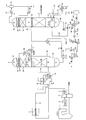
- FIG. 1 is an explanatory diagram of a CO 2 absorption system showing an embodiment of the present invention.
- the difference from the conventional system of FIG. 3 is that a part of the drain water in the pipe 49 separated by the CO 2 separator 48 is stored according to the liquid level of the storage tank 83 instead of the water supplied from the outside.
- a solid base such as Na 2 CO 3 was introduced into the tank 83, and the Na 2 CO 3 solution was supplied to the reclaimer 94 in accordance with the amount of HSS in the absorbent.
- the drain water separated by the CO 2 separator 48 passes through the drain pipe 49 and returns a part of the drain water returned through the flushing spray section 44 of the regeneration tower 40 according to the liquid level of the storage tank 83 by the flow control valve 81.
- An inorganic alkali salt for example, Na 2 CO 3
- the flow rate of the drain water is usually monitored by the flow meter 82, but can be managed using the level meter 85 instead.
- An appropriate amount of Na 2 CO 3 solution is supplied to the reclaimer 94 so that the HHS amount falls below a certain level while monitoring the input amount with the flow meter 87 according to the HSS amount in the absorbing solution. .
- FIG. 2 shows another embodiment of the present invention.
- the charging position is different from the embodiment of FIG. 1 in that the charging position of the Na 2 CO 3 solution is not the reclaimer 94 but the upstream reclaimer 94. This is the amine supply pipe 102.
- the CO 2 absorption system shown in FIGS. 1 and 2 solves the water balance problem associated with the operation of the reclaimer, which has been a problem with the conventional system shown in FIG. 3, and eliminates the need for water supply from outside the system. 2
- the absorption system can be operated under optimum conditions.
Abstract
【課題】吸収液再生装置(リクレーマ)を設けた排ガス中のCO2吸収システムにおいて、リクレーマの運用に伴う水バランスの問題を解決し、CO2吸収システムを最適な条件に保持する。 【解決手段】排ガス中のCO2を吸収塔内でアミン吸収液と接触させ、該CO2を吸収した吸収液を再生塔内で加熱してCO2を離脱させ、CO2離脱後の排ガスを冷却して凝縮水を分離し、その凝縮水を再生塔に循環させるCO2化学吸収設備と、該再生塔からアミン吸収液を抜き出し、その吸収液中に蓄積した熱安定性塩を蒸留法によって除去後、発生したアミン吸収液の蒸気を前記再生塔に供給する吸収液再生装置とを有するCO2化学吸収システムにおいて、再生塔でCO2離脱後の排ガスを冷却して得られた凝縮水の一部を分岐し、蒸留法においてアミン吸収液中に蓄積した熱安定性塩を除去するための前記吸収液再生装置に添加する無機アルカリ溶液の溶剤とするCO2化学吸収システムの制御方法。
Description
本発明は、二酸化炭素(CO2)化学吸収システムの制御方法に係り、特に蒸留式リクレーマを設置した場合に、CO2回収設備の水バランスを崩すことなく、補給水を最小限にしたシステムの運用を可能にする同システムの制御方法に関するものである。
近年、火力発電設備やボイラ設備では、多量の石炭及び重油等を燃料として用いており、大気汚染、地球温暖化の見地から、CO2の大気への大量排出が問題になっている。CO2の分離回収技術のひとつとして、アルカノールアミンのようなアミン化合物を用いた化学吸収法が広く知られている。
従来のCO2化学吸収システムを含む発電プラントの一例を図3に示す。この発電プラントは、主にボイラ1、脱硝装置2、エアヒータ3、電気集塵装置4、湿式脱硫装置5、プレスクラバー10、CO2吸収塔20、再生塔40、リボイラ60等から構成される。石炭等の化石燃料の燃焼することでボイラ1から排出される燃焼排ガスは脱硝装置2で窒素酸化物が除去された後、エアヒータ3で熱交換され、例えば120~170℃に冷却される。エアヒータ3を通過した排ガスは電気集塵機4で排ガス中のばいじんが除去され、さらに誘引ファンで昇圧した後、湿式脱硫装置5で硫黄酸化物(SO2)が除去される。湿式脱硫装置5出口ガス中には数十ppm程度のSO2が残存するのが通例であるが、該残存SO2によりCO2吸収塔20内のCO2吸収液の劣化を防止するため、CO2化学吸収設備の前処理設備としてプレスクラバー10が設置され、ここで残存SO2が極力低減(例えば1ppm以下)される。
CO2吸収塔20は、主にCO2吸収部である充填層21、吸収液スプレ部22、水洗部24、水洗スプレ部25、デミスタ26、水洗水溜め部27、冷却器28、及び水洗ポンプ29で構成される。排ガス中に含まれるCO2は、充填層21において、CO2吸収塔20上部のCO2吸収液噴霧部から供給されるCO2吸収液との気液接触により、CO2吸収液中へ吸収される。水洗部24では、吸収反応時の発熱により温度が上昇した脱CO2ガス23の冷却及びガスに同伴するミストを除去される。また、冷却器28によって冷却された水洗水は、水洗ポンプ29によって循環使用される。水洗部24上部にはデミスタ26が設置され、ガス中に同伴されたミストを除去した後、処理ガス37(脱CO2ガス)として系外に排出される。
CO2を吸収した吸収液は、吸収塔20下部の液溜めから吸収塔抜出しポンプ33により抜き出され、熱交換器34によって昇温後、再生塔40に送液される。再生塔40内では、スプレ部42から噴霧されたCO2をリッチに含む吸収液が充填層41に供給される。一方、再生塔40底部には、リボイラ60から蒸気供給配管65を介して蒸気が供給される。充填層41において、CO2をリッチに含む吸収液が底部より上昇してくる蒸気と気液接触することにより、吸収液中から気相中へ脱気される。脱気したCO2ガス中には、一部吸収液ミストが同伴されるが、水洗部43で該ミストが除去される。水洗部43上部にはデミスタ45が設置され、水洗部43等からガス中に同伴されたミストを除去した後、CO2ガス46として再生塔40上部より排出される。その後、CO2ガスは冷却器47によって約40℃に冷却され、CO2分離器48でガスと凝縮水に分離され、分離したCO2ガスはCO2液化設備(図示せず)へ導入され、凝縮した水は配管49を経てドレンポンプ50によって再生塔40の水洗スプレ部44に供給される。
一方、CO2を脱気したCO2吸収液は、再生塔液溜め部51に溜められた後、リボイラ液供給配管52を通ってリボイラ60に送液される。リボイラ60内部には伝熱管等が設置されており、CO2吸収液が蒸気供給配管を介して供給される蒸気62で間接加熱されることによりリボイラ60内部では蒸気が発生し、該蒸気が蒸気供給配管65を通って、再生塔に供給される。リボイラ60にて使用した蒸気62は伝熱管中でドレンとなり回収される。再生塔40底部の液溜め部に溜められたCO2吸収液は、再生塔液抜出し配管66を介して、熱交換器34及び冷却器29によって減温された後、CO2吸収塔に戻される。
一方、吸収塔20に供給される排ガスに僅かに混入するSO2のほとんどはCO2吸収液と反応し、熱安定性塩(Heat Stable Salt; HSSと略す)を形成する。HSSは吸収液に溶存するが、この反応は不可逆であるため、CO2吸収液とCO2との反応性が失われる。したがって、HSS濃度が上昇すればするほど、アミンとCO2の平衡関係が崩れるため、CO2再生エネルギーが増加していく。そこで、このHSSを除去するため、側流再生蒸留器(リクレーマと称することがある)94が設けられる。リクレーマ94は、熱安定性塩がある程度蓄積した吸収液の一部を抜き出し、無機アルカリ塩添加ラインを通して炭酸ナトリウム(Na2CO3)、炭酸カリウムなどの無機アルカリ塩を添加し、それぞれの硫酸塩として吸収液から除去するものである。リクレーマ94の操作は以下のように実施する。まず、CO2吸収設備20の運用を止める。CO2を脱気したCO2吸収液は、ポンプ93によりリクレーマ94に投入される液量を監視する流量計92と遮断弁91を介してリクレーマ94へ供給される。CO2吸収液は、リクレーマ94に設置されているレベル発信機95で水位を監視し、満水になるまで供給し、満水になると遮断弁91を閉じる。リクレーマ94には、予めNa2CO3などのNa系のアルカリ溶液を供給しておくことにより、アミン液中のHSSがアルカリ溶液と反応、すなわちアミンと結合していたSが解離し、Na2SO4となる。次に遮断弁98を開放、蒸気供給配管96を介し高温蒸気を供給することによりCO2吸収液を沸騰、蒸発させる。リクレーマ94に供給する蒸気供給配管96の蒸気は、アミンを沸騰、蒸発させることによりNa2SO4と分離させるため、通常、リボイラ60で使用される、アミンの熱分解を避けるために設定した蒸気温度より高温のものが使用される。蒸発したCO2吸収液は、アミン蒸気配管97を通り、再生塔40へ戻される。再生塔40を上昇したアミン吸収液は水洗部43で冷却され、さらに冷却器47で40℃程度に冷却されることで液化し、CO2分離器48、ドレンポンプ50を介した後、再生塔40へ戻される。一方、リクレーマ94内では次第にNa2SO4が濃縮していくが、アミン等が蒸発し、指定レベルまで水位が低下した時点でリクレーマ94への蒸気供給を終了する。遮断弁98を閉め、廃アミン配管99に設置された遮断弁100を開け、Na2SO4を含んだ廃アミン液が廃アミンタンク101へ排出される。
リクレーマでは、例えばNa2CO3等の塩基を投入し、アミンとNa2SO4に分離し、Na2SO4は系外に排出し、アミン吸収液は吸収塔に戻す。この場合、Na2CO3等は粉体のため、工学上定量供給が難しいので、バッファタンク等で一旦水に溶かした後、水溶液として系に投入される。
一方、CO2回収設備の水バランスは一般的には入口ガスが40℃で飽和、吸収塔出口、再生塔出口も同じ40℃で飽和となっているため、供給水がほとんどない。具体的には約100t/dのCO2回収プラントで約50kg/hの補給水しか足すことが出来ない。リクレーマーの処理速度は一般的にアミン循環液量の1%に満たない量で循環させるが、0.5%に設定したときで、系内のHSS濃度が2wt%のとき、約10kg/hのNa2CO3が必要となる。これを水に溶かすには約3倍の重量、すなわち30kg/hの水が必要である。アミン補給や水洗部24で使用する水洗水中のアミン濃縮防止の観点からこれ以上系内に補給水を追加することは厳しい。
上述の従来技術においては、回収設備の水バランスは一般的には入口ガスが40℃で飽和、吸収塔出口、再生塔出口も同じ40℃で飽和となっているため、供給可能な補給水量がほとんどないという問題があった。またアミン補給や水洗部24で使用する水洗水中のアミン濃縮防止の観点から、これ以上系内に補給水を追加することは厳しいという問題もあった。したがって、このような状況下でリクレーマを運用するためには、CO2吸収設備の水バランスを無視せざるを得ない、あるいは水バランスを保つため出口ガス温度を変え、放出する水分量を上昇させるを得ないという問題点があった。水バランスを変え、アミン濃度を低下させることは、余剰の水分を再生塔で加熱することになり、蒸気62の量が上昇し、用益費増加につながるため、望ましくない。
本発明の課題は、従来のリクレーマを設けたCO2吸収システムにおいて、問題となっていたリクレーマの運用に伴う水バランスの問題を解決し、系外からの水供給を最小限にして、CO2吸収システムを最適な条件に保持することにある。
上記課題は、図3の従来システムにおいて、CO2分離器48で分離した凝縮水をドレン配管49、ドレンポンプ50を介し、本来再生塔40に水洗スプレ部44を介して戻すはずのドレン水の一部を分岐して調整タンク83に貯留し、流量調整弁81により調整タンク83の液レベルを調整し、重量監視が可能なフィーダー84を通じてNa2CO3等の固体塩基を投入して、Na2CO3溶液濃度を調整し、吸収液中のHSS量にあわせて適量のNa2CO3溶液をリクレーマ94またはその上流のアミン供給ライン102へ供給することによって解決される。
すなわち、本願で特許請求される発明は以下のとおりである。
(1)化石燃料の燃焼装置から排出される排ガス中の硫黄酸化物を排煙脱硫装置で除去した後、二酸化炭素(CO2)吸収塔内でアミン吸収液と接触させて排ガス中のCO2を吸収し、次いで該CO2を吸収した吸収液を再生塔内で加熱してCO2を離脱させ、該CO2離脱後の排ガスを冷却して凝縮水を分離し、分離した凝縮水を前記再生塔に循環させる一方、該CO2離脱後の吸収液をリボイラを介して昇温した後、再生塔に循環すると共に、再生塔から抜き出したアミン吸収液を該再生塔に供給するアミン吸収液と熱交換した後、前記吸収塔に循環するCO2化学吸収設備と、該再生塔からアミン吸収液を抜き出し、該アミン吸収液中に蓄積した熱安定性塩を蒸留法によって除去した後、発生したアミン吸収液の蒸気を前記再生塔に供給する吸収液再生装置とを有するCO2化学吸収システムの制御方法であって、前記再生塔でCO2離脱後の排ガスを冷却して得られた凝縮水の一部を分岐し、前記蒸留法においてアミン吸収液中に蓄積した熱安定性塩を除去するために前記吸収液再生装置に添加する無機アルカリ塩溶液の溶剤とすることを特徴とするCO2化学吸収システムの制御方法。
(2)前記分岐した凝縮水を一旦調整タンク内に貯留し、これに無機アルカリを添加して該無機アルカリの濃度及び液レベルを調整した後、前記吸収液再生装置に供給される吸収液中の熱安定性塩の濃度に応じて、前記調整タンクの無機アルカリ塩溶液の量を調整し、前記吸収液再生装置に添加することを特徴とする(1)に記載の方法。
(3)前記無機アルカリ溶液の添加が、前記吸収液再生装置への吸収液供給配管への注入によって行なわれる(2)に記載の方法。
本発明によれば、水バランスを崩す要因となる、系外からの水供給がないため、リクレーマを運転していないときと同様に、システム内の水バランスを一定に保つことができ、したがって、CO2吸収システムを安定に稼動させることができる。
図1は、本発明の一実施例を示すCO2吸収システムの説明図である。図3の従来のシステムとの相違点は、外部から供給する水の代わりにCO2分離器48で分離した配管49のドレン水の一部を貯留タンク83の液レベルに応じてドレン水を貯留し、Na2CO3等の固体塩基をタンク83へ投入し、吸収液中のHSS量にあわせてNa2CO3溶液をリクレーマ94へ供給するようにしたことである。
CO2分離器48で分離したドレン水は、ドレン配管49を介し、再生塔40の水洗スプレ部44を介して戻すドレン水の一部を流量調整弁81にて貯留タンク83の液レベルに応じてドレン水を貯留する。その貯留タンク83へ重量監視が可能なフィーダー84を介して無機アルカリ塩(例えばNa2CO3)を投入する。ドレン水の流量は通常は流量計82にて監視するが、代わりにレベル計85を使用して管理することも可能である。ドレン水の流量とNa2CO3の投入とにより、吸収液中のNa2CO3濃度が調整されるが、サンプリングにより濃度を測定して調整してもよい。吸収液中のHSS量にあわせて、供給ポンプ85を介し、流量計87にて投入量を監視しながらHHS量が一定レベル以下になるように適量のNa2CO3溶液をリクレーマ94へ供給する。
図2は、本発明の他の実施例を示したもので、投入位置が図1の実施例と異なる点は、Na2CO3溶液の投入位置がリクレーマ94ではなく、その上流のリクレーマ94へのアミン供給配管102としたことである。
図1及び図2のCO2吸収システムによれば、図3の従来のシステムで問題となっていたリクレーマの運用に伴う水バランスの問題を解決し、系外からの水供給がなくてもCO2吸収システムを最適な条件で運用することができる。
1‥ボイラ、2‥脱硝装置、3‥エアヒーター、4‥乾式電気集塵装置、5‥湿式脱硫装置、6‥脱硫出口排ガス、10‥プレスクラバー、11‥吸収剤、12‥液溜め、14‥ 循環ポンプ、15‥冷却器、16‥スプレ部、17‥冷却水、18‥プレスクラバー出口ガス、20‥吸収塔、21‥充填層、22‥吸収液スプレ部、23‥脱CO2ガス、24‥水洗部、25‥水洗スプレ部、26‥デミスタ、27‥吸収塔水洗水溜め部、28‥冷却器、29‥水洗ポンプ、30‥冷却水、31‥冷却器、32‥ボイラ水、33‥吸収塔抜出しポンプ、34‥熱交換器、35‥再生塔液供給配管、36‥水洗水抜出し配管、37‥処理ガス、40‥ 再生塔、41‥充填層、42‥スプレ部、43‥水洗部、44‥水洗スプレ部、45‥デミスタ、46‥CO2ガス、47‥冷却器、48‥CO2分離器、49‥ドレン配管、50‥ドレンポンプ、51‥再生塔液溜め部、52‥リボイラ液供給配管、53‥冷却水、60‥リボイラ、61‥蒸気供給配管、62‥蒸気、63‥リボイラ液溜め部、64‥リボイラ液抜出し配管、65‥蒸気供給配管、66‥再生塔液抜出し配管、67‥凝縮水ドラム、68‥バイパス弁、69‥凝縮水ポンプ、70‥伝熱管、71‥凝縮水戻り配管、81‥流量調整弁、82‥流量計、83‥調整タンク、84‥フィーダ、85‥供給ポンプ、86‥流量計、91‥遮断弁、92‥流量計、93‥ポンプ、94‥リクレーマ、95‥レベル検出器、96‥蒸気供給配管、97‥アミン蒸気配管、98‥遮断弁、99‥廃アミン配管、100‥遮断弁、101‥廃アミンタンク、102‥アミン供給配管。
Claims (3)
- 化石燃料の燃焼装置から排出される排ガス中の硫黄酸化物を排煙脱硫装置で除去した後、二酸化炭素(CO2)吸収塔内でアミン吸収液と接触させて排ガス中のCO2を吸収し、次いで該CO2を吸収した吸収液を再生塔内で加熱してCO2を離脱させ、該CO2離脱後の排ガスを冷却して凝縮水を分離し、分離した凝縮水を前記再生塔に循環させる一方、該CO2離脱後の吸収液をリボイラを介して昇温した後、再生塔に循環すると共に、再生塔から抜き出したアミン吸収液を該再生塔に供給するアミン吸収液と熱交換した後、前記吸収塔に循環するCO2化学吸収設備と、該再生塔からアミン吸収液を抜き出し、該アミン吸収液中に蓄積した熱安定性塩を蒸留法によって除去した後、発生したアミン吸収液の蒸気を前記再生塔に供給する吸収液再生装置とを有するCO2化学吸収システムの制御方法であって、前記再生塔でCO2離脱後の排ガスを冷却して得られた凝縮水の一部を分岐し、前記蒸留法においてアミン吸収液中に蓄積した熱安定性塩を除去するために前記吸収液再生装置に添加する無機アルカリ塩溶液の溶剤とすることを特徴とするCO2化学吸収システムの制御方法。
- 前記分岐した凝縮水を一旦調整タンク内に貯留し、これに無機アルカリを添加して該無機アルカリの濃度及び液レベルを調整した後、前記吸収液再生装置に供給される吸収液中の熱安定性塩の濃度に応じて、前記調整タンクの無機アルカリ塩溶液の量を調整し、前記吸収液再生装置に添加することを特徴とする請求項1に記載の方法。
- 前記無機アルカリ溶液の添加が、前記吸収液再生装置への吸収液供給配管への注入によって行なわれる請求項2に記載の方法。
Priority Applications (5)
| Application Number | Priority Date | Filing Date | Title |
|---|---|---|---|
| PL12747482T PL2684595T3 (pl) | 2011-02-14 | 2012-02-14 | Sposób kontrolowania układu absorpcji chemicznej CO2 i układ absorpcji chemicznej CO2 |
| CA2826750A CA2826750C (en) | 2011-02-14 | 2012-02-14 | Method of controlling co2 chemical absorption system |
| US13/984,539 US20130315809A1 (en) | 2011-02-14 | 2012-02-14 | Method of controlling co2 chemical absorption system |
| ES12747482.3T ES2671579T3 (es) | 2011-02-14 | 2012-02-14 | Método para controlar un sistema de absorción química de CO2 y sistema de absorción química de CO2 |
| EP12747482.3A EP2684595B1 (en) | 2011-02-14 | 2012-02-14 | Method for controlling a system for chemically absorbing co2 and system for chemically absorbing co2 |
Applications Claiming Priority (2)
| Application Number | Priority Date | Filing Date | Title |
|---|---|---|---|
| JP2011028770A JP5636306B2 (ja) | 2011-02-14 | 2011-02-14 | Co2化学吸収システムの制御方法 |
| JP2011-028770 | 2011-02-14 |
Publications (1)
| Publication Number | Publication Date |
|---|---|
| WO2012111648A1 true WO2012111648A1 (ja) | 2012-08-23 |
Family
ID=46672567
Family Applications (1)
| Application Number | Title | Priority Date | Filing Date |
|---|---|---|---|
| PCT/JP2012/053349 WO2012111648A1 (ja) | 2011-02-14 | 2012-02-14 | Co2化学吸収システムの制御方法 |
Country Status (7)
| Country | Link |
|---|---|
| US (1) | US20130315809A1 (ja) |
| EP (1) | EP2684595B1 (ja) |
| JP (1) | JP5636306B2 (ja) |
| CA (1) | CA2826750C (ja) |
| ES (1) | ES2671579T3 (ja) |
| PL (1) | PL2684595T3 (ja) |
| WO (1) | WO2012111648A1 (ja) |
Cited By (2)
| Publication number | Priority date | Publication date | Assignee | Title |
|---|---|---|---|---|
| CN105251311A (zh) * | 2015-10-10 | 2016-01-20 | 江苏智道工程技术有限公司 | 回收多组分高浓度小流量间断有机废气有效成分的方法 |
| JP2016093788A (ja) * | 2014-11-14 | 2016-05-26 | 株式会社東芝 | 二酸化炭素回収装置および二酸化炭素回収方法 |
Families Citing this family (14)
| Publication number | Priority date | Publication date | Assignee | Title |
|---|---|---|---|---|
| KR101485953B1 (ko) * | 2013-03-20 | 2015-02-11 | 한국에너지기술연구원 | 양성자 주게 혼합물을 이용한 아민 흡수제의 재생방법 |
| JP6107443B2 (ja) | 2013-06-10 | 2017-04-05 | 株式会社Ihi | 不純物除去システム |
| US9192888B2 (en) | 2013-06-26 | 2015-11-24 | Uop Llc | Apparatuses and methods for removing acid gas from sour gas |
| JP6071838B2 (ja) * | 2013-10-18 | 2017-02-01 | 三菱重工業株式会社 | Co2又はh2s又はその双方の回収装置及び方法 |
| WO2016110965A1 (ja) * | 2015-01-07 | 2016-07-14 | 三菱日立パワーシステムズ株式会社 | ニトロソ化合物の処理方法および処理装置 |
| JP6345127B2 (ja) * | 2015-01-22 | 2018-06-20 | 三菱重工業株式会社 | 排ガス処理システム及び方法 |
| JP2016215174A (ja) * | 2015-05-26 | 2016-12-22 | 株式会社東芝 | 二酸化炭素回収システムおよび二酸化炭素回収システムの運転方法 |
| JP6598688B2 (ja) * | 2016-01-14 | 2019-10-30 | 三菱重工エンジニアリング株式会社 | 酸性ガス回収システム及びそれに用いるリクレーミング装置 |
| US11819777B2 (en) * | 2017-08-22 | 2023-11-21 | Saudi Arabian Oil Company | Systems and methods for enhancing amine agent recovery with a reclaimer |
| JP6987597B2 (ja) * | 2017-10-20 | 2022-01-05 | 三菱重工エンジニアリング株式会社 | リクレーミング装置及びリクレーミング方法 |
| JP6998174B2 (ja) * | 2017-10-20 | 2022-01-18 | 三菱重工エンジニアリング株式会社 | 酸性ガス除去装置及び酸性ガス除去方法 |
| US10625199B2 (en) | 2018-03-01 | 2020-04-21 | Mitsubishi Heavy Industries Engineering, Ltd. | CO2 recovery system and method of recovering CO2 |
| US11071942B2 (en) * | 2018-10-10 | 2021-07-27 | Mitsubishi Heavy Industries Engineering, Ltd. | Reclaiming apparatus and method, and CO2 recovery apparatus and method |
| CN113840803B (zh) * | 2019-05-28 | 2024-02-02 | 株式会社德山 | 二氧化碳气体及其它气体的回收方法 |
Citations (3)
| Publication number | Priority date | Publication date | Assignee | Title |
|---|---|---|---|---|
| JP2003053134A (ja) * | 2001-08-21 | 2003-02-25 | Kansai Electric Power Co Inc:The | 脱硫脱炭酸方法 |
| JP2006218415A (ja) * | 2005-02-10 | 2006-08-24 | Kansai Electric Power Co Inc:The | 排気ガスの処理方法及び処理装置 |
| JP2010201422A (ja) * | 2009-03-05 | 2010-09-16 | Ifp | 最適化された水洗セクションを用いた、吸収溶液を使用するガス脱酸方法 |
Family Cites Families (6)
| Publication number | Priority date | Publication date | Assignee | Title |
|---|---|---|---|---|
| US5397556A (en) * | 1992-12-16 | 1995-03-14 | The Regents Of The Unviversity Of California | Process for recovery of sulfur from acid gases |
| US7056482B2 (en) * | 2003-06-12 | 2006-06-06 | Cansolv Technologies Inc. | Method for recovery of CO2 from gas streams |
| US7384616B2 (en) * | 2005-06-20 | 2008-06-10 | Cansolv Technologies Inc. | Waste gas treatment process including removal of mercury |
| JP5595045B2 (ja) * | 2008-02-22 | 2014-09-24 | 三菱重工業株式会社 | Co2回収装置及びco2回収方法 |
| NO332812B1 (no) * | 2009-03-13 | 2013-01-21 | Aker Clean Carbon As | Amin utslippskontroll |
| NO20092229L (no) * | 2009-06-09 | 2010-12-10 | Aker Clean Carbon As | Reclaimer for absorbent |
-
2011
- 2011-02-14 JP JP2011028770A patent/JP5636306B2/ja active Active
-
2012
- 2012-02-14 EP EP12747482.3A patent/EP2684595B1/en active Active
- 2012-02-14 US US13/984,539 patent/US20130315809A1/en not_active Abandoned
- 2012-02-14 ES ES12747482.3T patent/ES2671579T3/es active Active
- 2012-02-14 PL PL12747482T patent/PL2684595T3/pl unknown
- 2012-02-14 WO PCT/JP2012/053349 patent/WO2012111648A1/ja active Application Filing
- 2012-02-14 CA CA2826750A patent/CA2826750C/en active Active
Patent Citations (3)
| Publication number | Priority date | Publication date | Assignee | Title |
|---|---|---|---|---|
| JP2003053134A (ja) * | 2001-08-21 | 2003-02-25 | Kansai Electric Power Co Inc:The | 脱硫脱炭酸方法 |
| JP2006218415A (ja) * | 2005-02-10 | 2006-08-24 | Kansai Electric Power Co Inc:The | 排気ガスの処理方法及び処理装置 |
| JP2010201422A (ja) * | 2009-03-05 | 2010-09-16 | Ifp | 最適化された水洗セクションを用いた、吸収溶液を使用するガス脱酸方法 |
Non-Patent Citations (1)
| Title |
|---|
| See also references of EP2684595A4 * |
Cited By (2)
| Publication number | Priority date | Publication date | Assignee | Title |
|---|---|---|---|---|
| JP2016093788A (ja) * | 2014-11-14 | 2016-05-26 | 株式会社東芝 | 二酸化炭素回収装置および二酸化炭素回収方法 |
| CN105251311A (zh) * | 2015-10-10 | 2016-01-20 | 江苏智道工程技术有限公司 | 回收多组分高浓度小流量间断有机废气有效成分的方法 |
Also Published As
| Publication number | Publication date |
|---|---|
| CA2826750A1 (en) | 2012-08-23 |
| EP2684595B1 (en) | 2018-03-21 |
| JP2012166139A (ja) | 2012-09-06 |
| ES2671579T3 (es) | 2018-06-07 |
| EP2684595A1 (en) | 2014-01-15 |
| EP2684595A4 (en) | 2015-01-07 |
| JP5636306B2 (ja) | 2014-12-03 |
| US20130315809A1 (en) | 2013-11-28 |
| PL2684595T3 (pl) | 2018-08-31 |
| CA2826750C (en) | 2019-06-18 |
Similar Documents
| Publication | Publication Date | Title |
|---|---|---|
| JP5636306B2 (ja) | Co2化学吸収システムの制御方法 | |
| JP5725992B2 (ja) | Co2回収設備 | |
| CN102325579B (zh) | 一种用于控制胺排放的方法及装置 | |
| US8329128B2 (en) | Gas treatment process and system | |
| JP5762253B2 (ja) | Co2化学吸収システムの制御方法 | |
| WO2012067101A1 (ja) | 二酸化炭素化学吸収システムの制御方法および装置 | |
| WO2013039041A1 (ja) | Co2回収装置およびco2回収方法 | |
| JP5959882B2 (ja) | 燃焼排ガス中の二酸化炭素化学吸収システム | |
| WO2013132962A1 (ja) | 劣化物濃度測定装置及び酸性ガス除去装置 | |
| JP5693295B2 (ja) | Co2回収装置およびco2回収装置の運転制御方法 | |
| JP2011240321A (ja) | 二酸化炭素除去装置を有する排ガス処理システム | |
| US9463411B2 (en) | Carbon dioxide chemical absorption system installed with vapor recompression equipment | |
| JP5639814B2 (ja) | 脱co2設備付き火力発電システム | |
| JP5738137B2 (ja) | Co2回収装置およびco2回収方法 | |
| WO2019078156A1 (ja) | 酸性ガス除去装置及び酸性ガス除去方法 | |
| CN109126392A (zh) | 一种采用离子液体进行烟气中co2捕集的装置及工艺 |
Legal Events
| Date | Code | Title | Description |
|---|---|---|---|
| 121 | Ep: the epo has been informed by wipo that ep was designated in this application |
Ref document number: 12747482 Country of ref document: EP Kind code of ref document: A1 |
|
| ENP | Entry into the national phase |
Ref document number: 2826750 Country of ref document: CA |
|
| WWE | Wipo information: entry into national phase |
Ref document number: 13984539 Country of ref document: US |
|
| NENP | Non-entry into the national phase |
Ref country code: DE |
|
| WWE | Wipo information: entry into national phase |
Ref document number: 2012747482 Country of ref document: EP |