EP2684539B1 - Superstructure - Google Patents
Superstructure Download PDFInfo
- Publication number
- EP2684539B1 EP2684539B1 EP13173563.1A EP13173563A EP2684539B1 EP 2684539 B1 EP2684539 B1 EP 2684539B1 EP 13173563 A EP13173563 A EP 13173563A EP 2684539 B1 EP2684539 B1 EP 2684539B1
- Authority
- EP
- European Patent Office
- Prior art keywords
- longitudinal
- implant
- casing
- lever
- main
- Prior art date
- Legal status (The legal status is an assumption and is not a legal conclusion. Google has not performed a legal analysis and makes no representation as to the accuracy of the status listed.)
- Active
Links
Images


Classifications
-
- A—HUMAN NECESSITIES
- A61—MEDICAL OR VETERINARY SCIENCE; HYGIENE
- A61C—DENTISTRY; APPARATUS OR METHODS FOR ORAL OR DENTAL HYGIENE
- A61C8/00—Means to be fixed to the jaw-bone for consolidating natural teeth or for fixing dental prostheses thereon; Dental implants; Implanting tools
- A61C8/0048—Connecting the upper structure to the implant, e.g. bridging bars
- A61C8/005—Connecting devices for joining an upper structure with an implant member, e.g. spacers
- A61C8/0053—Connecting devices for joining an upper structure with an implant member, e.g. spacers with angular adjustment means, e.g. ball and socket joint
-
- A—HUMAN NECESSITIES
- A61—MEDICAL OR VETERINARY SCIENCE; HYGIENE
- A61C—DENTISTRY; APPARATUS OR METHODS FOR ORAL OR DENTAL HYGIENE
- A61C8/00—Means to be fixed to the jaw-bone for consolidating natural teeth or for fixing dental prostheses thereon; Dental implants; Implanting tools
- A61C8/0048—Connecting the upper structure to the implant, e.g. bridging bars
- A61C8/005—Connecting devices for joining an upper structure with an implant member, e.g. spacers
- A61C8/0054—Connecting devices for joining an upper structure with an implant member, e.g. spacers having a cylindrical implant connecting part
-
- A—HUMAN NECESSITIES
- A61—MEDICAL OR VETERINARY SCIENCE; HYGIENE
- A61C—DENTISTRY; APPARATUS OR METHODS FOR ORAL OR DENTAL HYGIENE
- A61C8/00—Means to be fixed to the jaw-bone for consolidating natural teeth or for fixing dental prostheses thereon; Dental implants; Implanting tools
- A61C8/0048—Connecting the upper structure to the implant, e.g. bridging bars
- A61C8/005—Connecting devices for joining an upper structure with an implant member, e.g. spacers
- A61C8/0068—Connecting devices for joining an upper structure with an implant member, e.g. spacers with an additional screw
Definitions
- the present invention pertains to a dental superstructure attaching system for use with a dental implant. More specifically the present invention pertains to a system to be arranged in between a dental implant and a dental superstructure/framework, members thereof.
- a dental implant system The goal of a dental implant system is to restore the patient to normal function, comfort, aesthetic, speech and health regardless of the current oral condition.
- These implant systems are based on the implantation of dental implants, such as dental implants made of biocompatible titanium, through insertion into the patient's jawbone.
- dental implants such as dental implants made of biocompatible titanium
- biocompatible titanium started in Sweden as early as 1950, and has since then been further developed and spread world-wide.
- a number of implant systems entered the world market.
- US 5 842 864 A discloses a dental superstructure attaching system for use with a dental implant, having a longitudinal member connectable to an implant connecting member via a curved interface area.
- the longitudinal member comprises two lever members which can be urged away from each other to secure the longitudinal member to the implant connecting member.
- a casing which houses the lever members is used for connection to a dental superstructure by urging the lever members away from each other to secure the lever members in the casing.
- WO01/70127 describes an arrangement comprising a spacer element for an implant.
- the spacer implant has a screw bore at a fixed angle relative the longitudinal axis of the implant, such that a holder configured to support a superstructure may be mounted in said screw bore at the corresponding angle.
- the present invention preferably seeks to mitigate, alleviate or eliminate one or more of the above-identified deficiencies in the art and disadvantages singly or in any combination and solves at least the above mentioned problems by providing a device according to the appended patent claims.
- An object of the present invention is to provide a system for allowing a superstructure to be connected to said system without any visible attachment means.
- a further object of the present invention is to provide a single system which may be connected to a dental implant at various angles.
- a yet further object of the present invention is to provide a system allowing the superstructure to be connected to said system by means of a standard screw.
- a still further object of the present invention is to provide a system allowing for an improved fit between the system and the superstructure/framework, and to also provide a system allowing for a variety of possible materials for manufacturing the superstructure/framework.
- the general solution according to the invention is a two part superstructure attachment system forming a distance to be connected to a superstructure, which distance is angularly displaceable relative an implant and securable to said implant by a clamping effect caused by relative movement between the two parts, which in turn cooperates with a casing to be attached to the superstructure/framework.
- a dental superstructure attaching system for use with a dental implant, comprising a longitudinal member being connectable with an implant or an implant connecting member via an at least partially curved interface area, said longitudinal member comprising a main member and a lever member, wherein said longitudinal member further comprises means for urging said lever member and said main member away from each other, such that said longitudinal member is secured to said implant or implant connecting member, and a casing for attachment to a dental superstructure on the outer surface of the casing, said casing comprising a cavity for housing the longitudinal member, such that when urging said lever member and said main member away from each other, the longitudinal member is secured in said cavity.
- the present invention pertains to a system and devices thereof, for obtaining a dental superstructure, and subsequently a dental prosthesis, comprising said dental superstructure and an appropriate facing material thereon, without any form of screw channel mouth in the masticating surface.
- the system instead assures that the superstructure may be attached to a dental implant through a tightening screw lingually. In this way a more aesthetic and endurable construction may be obtained.
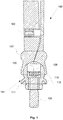
- a dental implant connecting member 101 and a longitudinal member 102 are disclosed.
- the dental implant connecting member 101and the longitudinal member 102 are parts of a superstructure attachment system, said system comprising the dental implant connecting member 101, the longitudinal member 102, and a casing 200, according to Figs. 3 and 4 .
- the longitudinal member 102 is adapted to be inserted into a casing 200, in accordance with Figs. 3 and 4 , which will be further described below, which in turn is connected toa dental superstructure.
- the longitudinal member 102 comprises two portions, a main member 102a and a lever member 102b, which in use are held together by a screw member arranged in a correspondingly threaded screw hole 103.
- the two members 102a, 102b have a substantially longitudinal extension, and are intended to extend distally from the implant connecting part 101, and therefore also distally from the jaw bone to which an implant (not shown) is secured.
- the screw hole 103 extends substantially transversally in respect of the longitudinal extension of the two members 102a, 102b, and runs at least through portion 102a.
- the thread of the screw hole 103 may be such that at least a part of the screw hole 103a in portion 102a is threaded.
- Portion 102b may comprise a receiving seat 103b, for receiving the screw member arranged in the screw hole 103a and protruding from an interface surface 105a on the portion 102a. In this way, the portion 102a may be pushed away from the portion 102b by screwing the screw member into the screw hole 103 and pushing onto the receiving seat 103b.
- the portion 102b may also have a threaded part in the receiving seat 103b. In this way the screw member may be prearranged in the screw hole, holding portion 102a and 102b together during application of the casing 200 thereon.
- the thread of the screw hole part in portion 102b may be threaded in the opposite direction to the thread in the screw hole 103a of portion 102a. In this way the separation action between portion 102a and 102b may be amplified, such that portion 102a and 102b are separated by two thread heights during every rotation of the screw member arranged in the screw hole 103.
- the implant connecting member 101 and the longitudinal member 102 are connected to each other at a curved interface area 106 forming a ball-socket joint.
- the ball-socket joint is formed by a partially spherically shaped protrusion 110 arranged at the distal end of the dental implant member 101, and a recess 104a, 104b having a corresponding inverted shape and configured to engage with said protrusion 110.
- a casing 200 is disclosed, in accordance with one embodiment of the invention.
- the casing 200 is to be inserted into a cavity in a dental superstructure.
- the dental superstructure can be provided with a predetermined cavity for receiving the casing 200, which cavity has a shape and size being known to for example the CAD/CAM equipment milling or shaping the dental superstructure.
- the longitudinal member 102 is intended to be received.
- the casing 200 may be manufactured in material being more resistant to strain and stress than the material of the dental superstructure.
- the casing 200 may be manufactured in stainless steel, titanium, CoCr etc., making it possible to manufacture the dental superstructure in more fragile materials, such as plastics.
- the casing 200 is substantially cylindrical, with a tubular cavity 201, extending into the casing 200 from the proximal end thereof.
- the distal end of the casing 200 is preferably closed, such that the cavity 201 ends in a distal bottom end wall 202.
- the cavity is adapted in size and shape to receive the longitudinal member 102.
- the casing 200 is provided with a proximal outer shoulder 203.
- the dental superstructure since the dental superstructure is manufactured and shaped to correspond to this exact cavity - the dental superstructure may bear upon the outer shoulder 203, which will facilitate arrangement and fixation of the casing into the dental superstructure and also distribute tensions and stresses between several cavity/casing positions in one dental superstructure, once the dental superstructure has been fixated to the dental implant, in accordance with below.
- a ledge 205 is formed in the proximal end of, i.e. at the opening 204 of, the cavity 201 .
- the ledge 205 is adapted in size and shape to correspond to the flange 107 of the longitudinal member 102.
- the interaction between the ledge 201 and the flange 107 creates a pivot point for said lever member 102b. Since the casing 200 has a predetermined shape corresponding to the longitudinal member 102, the cooperation between the flange 107 and the ledge 205 may be close, to minimize movement and play between the two.
- the casing 200 has a tubular wall 206, in accordance with above.
- the tubular wall 206 is provided with a through hole 207.
- the through hole 207 communicates with said cavity 201.
- the position of the through hole 207 corresponds in position to the through hole 103a of said main member 102a.
- the through hole 207 is also positioned distally of the proximal outer shoulder 203 and distally of the proximal ledge 205.
- the dental implant connecting member 101 is tightly attached to the dental implant by a screw 109 threadably engageable with the dental implant.
- the main member 102a and the lever member 102b of the longitudinal member 102 are fitted to engage with partially spherically shaped distal end of the implant connecting member 101.
- the longitudinal member 102 may be angularly displaced relative the longitudinal axis of the implant connecting member 101 by means of the ball-socket joint formed at the interface between the implant connecting member 101 and the longitudinal member 102.
- casings 200 are inserted into pre-shaped cavities, corresponding to the outer shape of the casing 200, and adhered thereto through gluing or cementing.
- the casings 200 then receive the longitudinal members 102 in the cavities 201 thereof.
- the cavities of the casings 200 are shaped such that the proximal mouth for receiving the longitudinal member comprises a seat, in form of the ledge 205, for the flange 107 in a proximal zone of the longitudinal member 102.
- the cooperation between the flange 107 and the corresponding ledge 205 of the casing 200 will enhance the leverage of the separation force from separation of the main member 102a and the lever member 102b, since a distinct leverage/pivot point will be formed at the interface between the two.
- the screw inserted into the screw bore 103 of the main member 102a is tightened such that it protrudes outside the main member 102a and consequently causing a relative movement between the lever member 102b and the main member 102a.
- the partially spherically shaped recess 104a, 104b of the longitudinal member 102 will consequently clamp longitudinal member 102 to the implant connecting member 101, such that the longitudinal member 102 is tightly connected to the implant connecting member.
- a superstructure may be attached to the system after the position of the longitudinal member 102 relative the implant connecting member 101 has been secured.
- the superstructure comprises at least one interior channel for receiving the casings 200, and thereby also the longitudinal members 102. More preferably, each one of the interior channels is reachable from the oral cavity by an opening, such that the superstructure may be further attached to the system by means of a screw. Hence, the opening is aligned with the through hole 207 of the casings 200 and the screw hole 103 of the main member 102a of the longitudinal member 102.
- the dental implant connecting member 101 is preferably a two-part piece, comprising a bolt and a fitting.
- the bolt has a threaded part 109 and tool receiving part 108 such that it may be tightly screwed into the implant.
- the fitting is equipped with a protrusion 112 and a recess 111 which engage with the implant and/or the bone of the patient for preventing rotational movement of the fitting relative the implant.
- the tool receiving part 108 is formed as a cylindrical or conical recess in the spherically shaped distal end, wherein the longitudinal axis of said recess is aligned with the longitudinal axis of the implant.
- the distal end is formed as a sphere integrally formed with the protrusion/recess part 111, 112, with a bore extending from the upper end through the sphere.
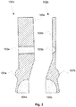
- the longitudinal member 102 is formed by the main member 102a and the lever member 102b.
- the longitudinal member is generally extending in a longitudinal direction and consists of three general parts; a cylindrical part, a flange, and a conical part.
- the cylindrical part is arranged at the distal end of the longitudinal member 102 and extends distally from the flange 107. Proximally of said flange 107, a conical part is arranged.
- the conical part comprises a proximal recess having a curvature corresponding to the distal end of the implant connecting member 101.
- the casing 200 is accordingly provided with a cavity 201 corresponding to longitudinal member 102, such that the longitudinal member 102 may be slid into the casing 200.
- the main member 102a and the lever member 102b are facing each other via the surfaces 105a, 105b, which form a longitudinal interface between the lever member 102b and the main member 102a.
- the distal portion of the interface between the surfaces 105a, 105b is preferably substantially aligned with the longitudinal axis of the longitudinal member 102, while the proximal portion of the interface between the surfaces 105a, 105b is preferably angled relative the longitudinal axis of the longitudinal member 102, such that the interface surface 105a has a normal facing proximally and transversally and the interface surface 105b faces distally and transversally, with respect to the longitudinal direction of the member 102.
- the angled interface portion is made longer; e.g., the entire interface area may be angled relative the longitudinal axis of the longitudinal member 102.
- the interface area formed by the surfaces 105a, 105b, when viewed from above, may also be planar or curved.
- the interface between the surfaces 105a, 105b is ending at a position being located at the center of the spherical recess 104a, 104b of the proximal end of the longitudinal member 102.
- the interface end point could be located slightly off-center.
- the through hole 103a of the main member 102a is substantially perpendicular to the longitudinal axis of the main member 102a.
- the lever member 102b has a corresponding seat 103b for receiving a screw protruding through said main member 102a.
- the screw hole 103a, 103b may be arranged differently and the engaging screw members may then be correspondingly adapted.
- the screw hole 103a, 103b may extend through both the portions 102a, 102b, but the screw hole part corresponding to portion 102a having opposite threading direction than the threading direction in the screw hole part corresponding to portion 102b.
- the screw member may have the corresponding threads, such that screwing action on the screw member in the screw hole 103 will result in increased separation effect. One rotation of the screw member will then result in a separation of the portions 102a, 102b corresponding to two thread heights.
- the threaded holes 103a, 103b may be arranged at a different angle such that the mouth of the through hole 103a is directed slightly distally.
- the diameter of the longitudinal member 102 is preferably in the range of 2 to 5 mm, such that it may be accommodated within the oral cavity while still providing sufficient strength and stability to the casing 200, and thus the superstructure.
- the total length of the longitudinal member is in the range of 10 to 15 mm, and hence the displacement of the lever member 102b relative the main member 102a is sub-millimeter at the most distal end in order to provide sufficient clamping of the longitudinal member 102 to the implant connecting member 101.
- the cavity 201 of the casing 200 is adapted to snuggly receive a longitudinal member 102 in a sliding manner.
Claims (9)
- Système d'attache de superstructure dentaire pour une utilisation avec un implant dentaire, ledit système d'attache de superstructure dentaire comprenant :(i) un organe longitudinal (102) qui peut être connecté avec un implant ou un organe de raccordement d'implant (101) via une zone d'interface au moins partiellement incurvée (106) à l'extrémité proximale dudit organe longitudinal (102), ledit organe longitudinal (102) comprenant
un organe principal (102a) et
un organe de levier (102b),
dans lequel ledit organe longitudinal (102) comprend en outre un moyen (103) permettant de pousser ledit organe de levier (102b) et ledit organe principal (102a) en éloignement l'un de l'autre, de telle sorte que ledit organe longitudinal (102) soit arrimé audit implant ou organe de raccordement d'implant (101) ; et(ii) un boîtier (200) pour attache à une superstructure dentaire sur la surface externe du boîtier (200), ledit boîtier (200) comprenant
une cavité (201) destinée à loger l'organe longitudinal (102), de telle sorte que lors de la poussée dudit organe de levier (102b) et dudit organe principal (102a) en éloignement l'un de l'autre, l'organe longitudinal (102) soit arrimé dans ladite cavité (201),
dans lequel ledit organe de levier (102b) comprend une assise de réception filetée (103b) alignée axialement avec un trou traversant fileté (103a) de l'organe principal (102a), de telle sorte que ladite assise de réception (103b) et ledit trou traversant (103a) soient configurés pour recevoir une vis. - Système selon la revendication 1, comprenant en outre un organe de raccordement d'implant (101), et dans lequel l'extrémité proximale dudit organe longitudinal (102) comprend un évidement de forme partiellement sphérique (104a, 104b), et dans lequel l'extrémité distale dudit organe de raccordement d'implant (101) comprend une protubérance de forme partiellement sphérique (110).
- Système selon la revendication 1 ou 2, dans lequel l'organe longitudinal (102) a une section circulaire.
- Système selon la revendication 3, dans lequel l'organe longitudinal (102) comprend une bride (107) agencée entre l'extrémité proximale et l'extrémité distale dudit organe longitudinal (102), et dans lequel le boîtier (200) comprend une pièce d'appui (205) au niveau d'une ouverture d'extrémité proximale (204) de ladite cavité (201), correspondant à ladite bride (107), de telle sorte qu'un point de pivot pour ledit organe de levier (102b) soit formé au niveau de la surface d'interaction entre la bride (107) et la pièce d'appui (205).
- Système selon l'une quelconque des revendications 1 à 4, dans lequel une première portion d'une interface longitudinale entre l'organe principal (102a) et l'organe de levier (102b) est inclinée par rapport à l'axe longitudinal de l'organe longitudinal (102).
- Système selon la revendication 5, dans lequel une seconde portion de l'interface longitudinale entre l'organe principal (102a) et l'organe de levier (102b) est parallèle à l'axe longitudinal de l'organe longitudinal (102).
- Système selon l'une quelconque de revendications 1 à 6, dans lequel ledit moyen (103) destiné à pousser ledit organe de levier (102b) et ledit organe principal (102a) en éloignement l'un de l'autre comprend une vis qui est insérée dans le trou traversant fileté (103a) dudit organe principal (102a) et se mettant en prise avec lesdits filets de telle sorte qu'il fasse saillie hors de l'organe principal (102a) et pousse l'organe de levier (102b) en éloignement dudit organe principal (102a), et ledit boîtier (200) ayant un trou traversant (207) dans une paroi latérale (206) de celui-ci, ledit trou traversant (207) communiquant avec ladite cavité (201) et correspondant en position au trou traversant (103a) dudit organe principal (102a).
- Système selon la revendication 7, dans lequel ladite vis est configurée pour raccorder l'organe principal (102a) avec l'organe de levier (102b) tout en permettant dans le même temps un mouvement relatif de l'organe principal (102a) et de l'organe de levier (102b).
- Système selon la revendication 8, dans lequel les filets du trou traversant (103a) sont dans un sens opposé à celui des filets de l'assise de réception (103b).
Applications Claiming Priority (1)
| Application Number | Priority Date | Filing Date | Title |
|---|---|---|---|
| SE1250815A SE539272C2 (sv) | 2012-07-11 | 2012-07-11 | Superstruktur och metoder för tillverkning av densamma |
Publications (2)
| Publication Number | Publication Date |
|---|---|
| EP2684539A1 EP2684539A1 (fr) | 2014-01-15 |
| EP2684539B1 true EP2684539B1 (fr) | 2017-04-05 |
Family
ID=48746270
Family Applications (1)
| Application Number | Title | Priority Date | Filing Date |
|---|---|---|---|
| EP13173563.1A Active EP2684539B1 (fr) | 2012-07-11 | 2013-06-25 | Superstructure |
Country Status (10)
| Country | Link |
|---|---|
| US (1) | US9072567B2 (fr) |
| EP (1) | EP2684539B1 (fr) |
| JP (1) | JP6317894B2 (fr) |
| KR (1) | KR101873605B1 (fr) |
| CN (1) | CN103637849B (fr) |
| AU (1) | AU2013206530B2 (fr) |
| BR (1) | BR102013017717A2 (fr) |
| CA (1) | CA2819745C (fr) |
| ES (1) | ES2626140T3 (fr) |
| SE (1) | SE539272C2 (fr) |
Families Citing this family (5)
| Publication number | Priority date | Publication date | Assignee | Title |
|---|---|---|---|---|
| AU2012258258B2 (en) * | 2011-05-16 | 2015-05-14 | Heraeus Kulzer Nordic Ab | Dental superstructure attaching system and methods for attaching a dental superstructure to a dental implant |
| KR200471489Y1 (ko) * | 2012-04-04 | 2014-02-28 | 왕제원 | 각도조절과 위치조절이 자유로운 틀니 고정용 어태치먼트 |
| EP3125818B1 (fr) * | 2014-04-04 | 2019-08-21 | Addbutment Dental AB | Système de fixation pour implants dentaires |
| EP3020362B1 (fr) * | 2014-11-12 | 2017-09-13 | Main Brilliant Co. Ltd. | Dispositif prosthodontique avec suprastructure détachable |
| WO2016203030A1 (fr) * | 2015-06-19 | 2016-12-22 | Nobel Biocare Services Ag | Ensemble de liaison dentaire et procédé de production de prothèse dentaire |
Family Cites Families (30)
| Publication number | Priority date | Publication date | Assignee | Title |
|---|---|---|---|---|
| US2599044A (en) * | 1949-01-03 | 1952-06-03 | John E Brennan | Artificial denture and retainer therefor |
| US3618212A (en) * | 1969-11-19 | 1971-11-09 | Bernard Weissman | Dental prosthetic construction |
| SE328961B (fr) * | 1970-03-25 | 1970-09-28 | Aga Ab | |
| US4854874A (en) * | 1981-12-14 | 1989-08-08 | Neuwirth Peyton S | Oral implant |
| US4531917A (en) * | 1984-04-02 | 1985-07-30 | Linkow Leonard I | Detachable post for an osseous implant |
| JPS622811U (fr) * | 1985-06-21 | 1987-01-09 | ||
| DE3534751A1 (de) * | 1985-09-28 | 1987-04-09 | Krupp Gmbh | Verfahren zur herstellung loesbarer zahnprothesen und zahnprothetische verbindungsvorrichtung |
| DE3615733A1 (de) * | 1986-05-09 | 1987-11-12 | Leitz Ernst Gmbh | Zahnwurzel-implantat hoher dauerschwingfestigkeit |
| US4932868A (en) * | 1986-09-04 | 1990-06-12 | Vent-Plant Corporation | Submergible screw-type dental implant and method of utilization |
| US4955811A (en) * | 1988-06-23 | 1990-09-11 | Implant Innovations, Inc. | Non-rotational single-tooth prosthodontic restoration |
| US5092770A (en) * | 1990-02-05 | 1992-03-03 | Zakula Michael R | Denture anchoring system |
| US5071350A (en) * | 1990-03-21 | 1991-12-10 | Core-Vent Corporation | Tiltable, adjustable, insert for a dental implant |
| US5073110A (en) * | 1990-05-21 | 1991-12-17 | Implant Plastics Corporation | Articulating ball coping and associated devices |
| US5125839A (en) * | 1990-09-28 | 1992-06-30 | Abraham Ingber | Dental implant system |
| US5116225A (en) * | 1990-10-17 | 1992-05-26 | Riera Juan C A | Angulated abutment for osseointegrated implants |
| US5106299A (en) * | 1991-06-25 | 1992-04-21 | Ghalili Kambiz M | Dental prosthesis for use with an oral implant, and method of installation |
| US5133662A (en) * | 1991-09-03 | 1992-07-28 | Metcalfe Edwin R | Tooth implant device |
| US5520540A (en) * | 1992-06-19 | 1996-05-28 | Rhein 83 S.N.C. Di Nardi Ezio & C. Zago, 10 | Quick coupling device for dental prosthesis |
| IT233018Y1 (it) * | 1993-09-22 | 2000-01-26 | Rhein 83 S N C Di Nardi Ezio & | Dispositivo per realizzare attacchi rapidi per protesi dentarie |
| US5527182A (en) | 1993-12-23 | 1996-06-18 | Adt Advanced Dental Technologies, Ltd. | Implant abutment systems, devices, and techniques |
| DE9419508U1 (de) * | 1994-12-06 | 1996-04-04 | Unger Heinz Dieter Dr Med Dent | Prothetische Suprakonstruktion |
| DE29514042U1 (de) * | 1995-09-01 | 1997-01-09 | Unger Heinz Dieter Dr Med Dent | Anker für Implantatkörper und Richtvorrichtung zu deren Ausrichtung |
| US5967781A (en) * | 1998-06-26 | 1999-10-19 | Implant Systems, Inc. | Prosthodontic abutment apparatus and method |
| SE516040C2 (sv) | 2000-03-23 | 2001-11-12 | Nobel Biocare Ab | Arrangemang innefattande distans för implantat samt sådan distans och skruvmejsel för distansens fastsättning |
| SE522965C2 (sv) * | 2000-12-29 | 2004-03-16 | Nobel Biocare Ab | Anordning för att åstadkomma lägesbestämning |
| SE520764C2 (sv) * | 2001-12-28 | 2003-08-19 | Nobel Biocare Ab | Anordning och arrangemang vid implantat |
| US6843653B2 (en) * | 2002-06-04 | 2005-01-18 | Joseph Carlton | Dental implant |
| KR101484493B1 (ko) * | 2006-10-02 | 2015-01-28 | 상드르에+메토 에스아 | 치아 대체물을 고정하기 위한 앵커 |
| US20080241790A1 (en) * | 2007-03-30 | 2008-10-02 | Gittleman Neal B | CIP of Expanding Ball Lock Oral Prosthesis Alignment Apparatus |
| US8348668B2 (en) * | 2008-09-25 | 2013-01-08 | Simply Dental Ab | Dental implant, and superstructure therefore |
-
2012
- 2012-07-11 SE SE1250815A patent/SE539272C2/sv unknown
-
2013
- 2013-06-25 EP EP13173563.1A patent/EP2684539B1/fr active Active
- 2013-06-25 AU AU2013206530A patent/AU2013206530B2/en not_active Ceased
- 2013-06-25 ES ES13173563.1T patent/ES2626140T3/es active Active
- 2013-06-26 CA CA2819745A patent/CA2819745C/fr active Active
- 2013-07-05 JP JP2013141299A patent/JP6317894B2/ja active Active
- 2013-07-05 US US13/935,677 patent/US9072567B2/en active Active
- 2013-07-08 KR KR1020130079869A patent/KR101873605B1/ko active IP Right Grant
- 2013-07-10 CN CN201310288738.8A patent/CN103637849B/zh active Active
- 2013-07-10 BR BR102013017717A patent/BR102013017717A2/pt not_active IP Right Cessation
Also Published As
| Publication number | Publication date |
|---|---|
| JP2014014682A (ja) | 2014-01-30 |
| US9072567B2 (en) | 2015-07-07 |
| ES2626140T3 (es) | 2017-07-24 |
| KR20140008252A (ko) | 2014-01-21 |
| SE1250815A1 (sv) | 2014-01-12 |
| EP2684539A1 (fr) | 2014-01-15 |
| JP6317894B2 (ja) | 2018-04-25 |
| SE539272C2 (sv) | 2017-06-07 |
| CA2819745A1 (fr) | 2014-01-11 |
| BR102013017717A2 (pt) | 2016-01-26 |
| CN103637849B (zh) | 2016-08-10 |
| US20140017631A1 (en) | 2014-01-16 |
| AU2013206530A1 (en) | 2014-01-30 |
| CN103637849A (zh) | 2014-03-19 |
| AU2013206530B2 (en) | 2015-10-29 |
| CA2819745C (fr) | 2017-03-21 |
| KR101873605B1 (ko) | 2018-07-02 |
Similar Documents
| Publication | Publication Date | Title |
|---|---|---|
| US11730572B2 (en) | Apparatus for attaching a dental component to a dental implant | |
| EP2684539B1 (fr) | Superstructure | |
| CA2853327C (fr) | Systeme de montage d'un remplacement dentaire | |
| EP2709553B1 (fr) | Système de fixation de superstructure dentaire et procédés pour fixer une superstructure dentaire à un implant dentaire | |
| EP2346435B1 (fr) | Superstructure pour un implant dentaire | |
| WO2016170376A1 (fr) | Structure permettant un réglage angulaire continu pour fixer un dispositif dentaire unique dans un implant | |
| EP3372190B1 (fr) | Ensemble d'implant dentaire et de composants prothétiques, qui comprend un manchon transépithélial avec raccord supérieur antirotatif | |
| CN113573661B (zh) | 用于安装牙假体的工具组件和安装方法 | |
| EP3490492B1 (fr) | Système de fixation pour fixer une prothèse dentaire à un implant dentaire |
Legal Events
| Date | Code | Title | Description |
|---|---|---|---|
| PUAI | Public reference made under article 153(3) epc to a published international application that has entered the european phase |
Free format text: ORIGINAL CODE: 0009012 |
|
| AK | Designated contracting states |
Kind code of ref document: A1 Designated state(s): AL AT BE BG CH CY CZ DE DK EE ES FI FR GB GR HR HU IE IS IT LI LT LU LV MC MK MT NL NO PL PT RO RS SE SI SK SM TR |
|
| AX | Request for extension of the european patent |
Extension state: BA ME |
|
| RIN1 | Information on inventor provided before grant (corrected) |
Inventor name: BENZON, STURE |
|
| 17P | Request for examination filed |
Effective date: 20140715 |
|
| RBV | Designated contracting states (corrected) |
Designated state(s): AL AT BE BG CH CY CZ DE DK EE ES FI FR GB GR HR HU IE IS IT LI LT LU LV MC MK MT NL NO PL PT RO RS SE SI SK SM TR |
|
| RAP1 | Party data changed (applicant data changed or rights of an application transferred) |
Owner name: HERAEUS KULZER NORDIC AB |
|
| 17Q | First examination report despatched |
Effective date: 20160129 |
|
| RAP1 | Party data changed (applicant data changed or rights of an application transferred) |
Owner name: HERAEUS KULZER GMBH |
|
| GRAP | Despatch of communication of intention to grant a patent |
Free format text: ORIGINAL CODE: EPIDOSNIGR1 |
|
| INTG | Intention to grant announced |
Effective date: 20161207 |
|
| GRAS | Grant fee paid |
Free format text: ORIGINAL CODE: EPIDOSNIGR3 |
|
| GRAA | (expected) grant |
Free format text: ORIGINAL CODE: 0009210 |
|
| AK | Designated contracting states |
Kind code of ref document: B1 Designated state(s): AL AT BE BG CH CY CZ DE DK EE ES FI FR GB GR HR HU IE IS IT LI LT LU LV MC MK MT NL NO PL PT RO RS SE SI SK SM TR |
|
| REG | Reference to a national code |
Ref country code: GB Ref legal event code: FG4D |
|
| REG | Reference to a national code |
Ref country code: CH Ref legal event code: EP |
|
| REG | Reference to a national code |
Ref country code: AT Ref legal event code: REF Ref document number: 881057 Country of ref document: AT Kind code of ref document: T Effective date: 20170415 |
|
| REG | Reference to a national code |
Ref country code: IE Ref legal event code: FG4D |
|
| REG | Reference to a national code |
Ref country code: DE Ref legal event code: R096 Ref document number: 602013019356 Country of ref document: DE |
|
| REG | Reference to a national code |
Ref country code: CH Ref legal event code: NV Representative=s name: ISLER AND PEDRAZZINI AG, CH |
|
| REG | Reference to a national code |
Ref country code: FR Ref legal event code: PLFP Year of fee payment: 5 |
|
| REG | Reference to a national code |
Ref country code: ES Ref legal event code: FG2A Ref document number: 2626140 Country of ref document: ES Kind code of ref document: T3 Effective date: 20170724 |
|
| REG | Reference to a national code |
Ref country code: SE Ref legal event code: TRGR |
|
| REG | Reference to a national code |
Ref country code: NL Ref legal event code: MP Effective date: 20170405 |
|
| REG | Reference to a national code |
Ref country code: LT Ref legal event code: MG4D |
|
| REG | Reference to a national code |
Ref country code: DE Ref legal event code: R082 Ref document number: 602013019356 Country of ref document: DE Representative=s name: BENDELE, TANJA, DIPL.-CHEM. DR. RER. NAT., DE Ref country code: DE Ref legal event code: R081 Ref document number: 602013019356 Country of ref document: DE Owner name: KULZER GMBH, DE Free format text: FORMER OWNER: HERAEUS KULZER GMBH, 63450 HANAU, DE |
|
| REG | Reference to a national code |
Ref country code: AT Ref legal event code: MK05 Ref document number: 881057 Country of ref document: AT Kind code of ref document: T Effective date: 20170405 |
|
| RAP2 | Party data changed (patent owner data changed or rights of a patent transferred) |
Owner name: KULZER GMBH |
|
| PG25 | Lapsed in a contracting state [announced via postgrant information from national office to epo] |
Ref country code: NL Free format text: LAPSE BECAUSE OF FAILURE TO SUBMIT A TRANSLATION OF THE DESCRIPTION OR TO PAY THE FEE WITHIN THE PRESCRIBED TIME-LIMIT Effective date: 20170405 |
|
| PG25 | Lapsed in a contracting state [announced via postgrant information from national office to epo] |
Ref country code: NO Free format text: LAPSE BECAUSE OF FAILURE TO SUBMIT A TRANSLATION OF THE DESCRIPTION OR TO PAY THE FEE WITHIN THE PRESCRIBED TIME-LIMIT Effective date: 20170705 Ref country code: FI Free format text: LAPSE BECAUSE OF FAILURE TO SUBMIT A TRANSLATION OF THE DESCRIPTION OR TO PAY THE FEE WITHIN THE PRESCRIBED TIME-LIMIT Effective date: 20170405 Ref country code: LT Free format text: LAPSE BECAUSE OF FAILURE TO SUBMIT A TRANSLATION OF THE DESCRIPTION OR TO PAY THE FEE WITHIN THE PRESCRIBED TIME-LIMIT Effective date: 20170405 Ref country code: GR Free format text: LAPSE BECAUSE OF FAILURE TO SUBMIT A TRANSLATION OF THE DESCRIPTION OR TO PAY THE FEE WITHIN THE PRESCRIBED TIME-LIMIT Effective date: 20170706 Ref country code: HR Free format text: LAPSE BECAUSE OF FAILURE TO SUBMIT A TRANSLATION OF THE DESCRIPTION OR TO PAY THE FEE WITHIN THE PRESCRIBED TIME-LIMIT Effective date: 20170405 Ref country code: AT Free format text: LAPSE BECAUSE OF FAILURE TO SUBMIT A TRANSLATION OF THE DESCRIPTION OR TO PAY THE FEE WITHIN THE PRESCRIBED TIME-LIMIT Effective date: 20170405 |
|
| PG25 | Lapsed in a contracting state [announced via postgrant information from national office to epo] |
Ref country code: RS Free format text: LAPSE BECAUSE OF FAILURE TO SUBMIT A TRANSLATION OF THE DESCRIPTION OR TO PAY THE FEE WITHIN THE PRESCRIBED TIME-LIMIT Effective date: 20170405 Ref country code: BG Free format text: LAPSE BECAUSE OF FAILURE TO SUBMIT A TRANSLATION OF THE DESCRIPTION OR TO PAY THE FEE WITHIN THE PRESCRIBED TIME-LIMIT Effective date: 20170705 Ref country code: PL Free format text: LAPSE BECAUSE OF FAILURE TO SUBMIT A TRANSLATION OF THE DESCRIPTION OR TO PAY THE FEE WITHIN THE PRESCRIBED TIME-LIMIT Effective date: 20170405 Ref country code: LV Free format text: LAPSE BECAUSE OF FAILURE TO SUBMIT A TRANSLATION OF THE DESCRIPTION OR TO PAY THE FEE WITHIN THE PRESCRIBED TIME-LIMIT Effective date: 20170405 Ref country code: IS Free format text: LAPSE BECAUSE OF FAILURE TO SUBMIT A TRANSLATION OF THE DESCRIPTION OR TO PAY THE FEE WITHIN THE PRESCRIBED TIME-LIMIT Effective date: 20170805 |
|
| REG | Reference to a national code |
Ref country code: DE Ref legal event code: R097 Ref document number: 602013019356 Country of ref document: DE |
|
| PG25 | Lapsed in a contracting state [announced via postgrant information from national office to epo] |
Ref country code: SK Free format text: LAPSE BECAUSE OF FAILURE TO SUBMIT A TRANSLATION OF THE DESCRIPTION OR TO PAY THE FEE WITHIN THE PRESCRIBED TIME-LIMIT Effective date: 20170405 Ref country code: RO Free format text: LAPSE BECAUSE OF FAILURE TO SUBMIT A TRANSLATION OF THE DESCRIPTION OR TO PAY THE FEE WITHIN THE PRESCRIBED TIME-LIMIT Effective date: 20170405 Ref country code: CZ Free format text: LAPSE BECAUSE OF FAILURE TO SUBMIT A TRANSLATION OF THE DESCRIPTION OR TO PAY THE FEE WITHIN THE PRESCRIBED TIME-LIMIT Effective date: 20170405 Ref country code: MC Free format text: LAPSE BECAUSE OF FAILURE TO SUBMIT A TRANSLATION OF THE DESCRIPTION OR TO PAY THE FEE WITHIN THE PRESCRIBED TIME-LIMIT Effective date: 20170405 Ref country code: EE Free format text: LAPSE BECAUSE OF FAILURE TO SUBMIT A TRANSLATION OF THE DESCRIPTION OR TO PAY THE FEE WITHIN THE PRESCRIBED TIME-LIMIT Effective date: 20170405 Ref country code: DK Free format text: LAPSE BECAUSE OF FAILURE TO SUBMIT A TRANSLATION OF THE DESCRIPTION OR TO PAY THE FEE WITHIN THE PRESCRIBED TIME-LIMIT Effective date: 20170405 |
|
| PLBE | No opposition filed within time limit |
Free format text: ORIGINAL CODE: 0009261 |
|
| STAA | Information on the status of an ep patent application or granted ep patent |
Free format text: STATUS: NO OPPOSITION FILED WITHIN TIME LIMIT |
|
| PG25 | Lapsed in a contracting state [announced via postgrant information from national office to epo] |
Ref country code: SM Free format text: LAPSE BECAUSE OF FAILURE TO SUBMIT A TRANSLATION OF THE DESCRIPTION OR TO PAY THE FEE WITHIN THE PRESCRIBED TIME-LIMIT Effective date: 20170405 |
|
| 26N | No opposition filed |
Effective date: 20180108 |
|
| REG | Reference to a national code |
Ref country code: IE Ref legal event code: MM4A |
|
| PG25 | Lapsed in a contracting state [announced via postgrant information from national office to epo] |
Ref country code: LU Free format text: LAPSE BECAUSE OF NON-PAYMENT OF DUE FEES Effective date: 20170625 Ref country code: IE Free format text: LAPSE BECAUSE OF NON-PAYMENT OF DUE FEES Effective date: 20170625 |
|
| PG25 | Lapsed in a contracting state [announced via postgrant information from national office to epo] |
Ref country code: SI Free format text: LAPSE BECAUSE OF FAILURE TO SUBMIT A TRANSLATION OF THE DESCRIPTION OR TO PAY THE FEE WITHIN THE PRESCRIBED TIME-LIMIT Effective date: 20170405 |
|
| REG | Reference to a national code |
Ref country code: BE Ref legal event code: MM Effective date: 20170630 |
|
| REG | Reference to a national code |
Ref country code: FR Ref legal event code: PLFP Year of fee payment: 6 |
|
| PG25 | Lapsed in a contracting state [announced via postgrant information from national office to epo] |
Ref country code: BE Free format text: LAPSE BECAUSE OF NON-PAYMENT OF DUE FEES Effective date: 20170630 |
|
| PGFP | Annual fee paid to national office [announced via postgrant information from national office to epo] |
Ref country code: FR Payment date: 20180620 Year of fee payment: 6 |
|
| PG25 | Lapsed in a contracting state [announced via postgrant information from national office to epo] |
Ref country code: MT Free format text: LAPSE BECAUSE OF NON-PAYMENT OF DUE FEES Effective date: 20170625 |
|
| PGFP | Annual fee paid to national office [announced via postgrant information from national office to epo] |
Ref country code: IT Payment date: 20180627 Year of fee payment: 6 Ref country code: ES Payment date: 20180724 Year of fee payment: 6 |
|
| PG25 | Lapsed in a contracting state [announced via postgrant information from national office to epo] |
Ref country code: HU Free format text: LAPSE BECAUSE OF FAILURE TO SUBMIT A TRANSLATION OF THE DESCRIPTION OR TO PAY THE FEE WITHIN THE PRESCRIBED TIME-LIMIT; INVALID AB INITIO Effective date: 20130625 |
|
| PG25 | Lapsed in a contracting state [announced via postgrant information from national office to epo] |
Ref country code: CY Free format text: LAPSE BECAUSE OF NON-PAYMENT OF DUE FEES Effective date: 20170405 |
|
| PG25 | Lapsed in a contracting state [announced via postgrant information from national office to epo] |
Ref country code: MK Free format text: LAPSE BECAUSE OF FAILURE TO SUBMIT A TRANSLATION OF THE DESCRIPTION OR TO PAY THE FEE WITHIN THE PRESCRIBED TIME-LIMIT Effective date: 20170405 |
|
| PG25 | Lapsed in a contracting state [announced via postgrant information from national office to epo] |
Ref country code: TR Free format text: LAPSE BECAUSE OF FAILURE TO SUBMIT A TRANSLATION OF THE DESCRIPTION OR TO PAY THE FEE WITHIN THE PRESCRIBED TIME-LIMIT Effective date: 20170405 |
|
| PG25 | Lapsed in a contracting state [announced via postgrant information from national office to epo] |
Ref country code: IT Free format text: LAPSE BECAUSE OF NON-PAYMENT OF DUE FEES Effective date: 20190625 |
|
| PG25 | Lapsed in a contracting state [announced via postgrant information from national office to epo] |
Ref country code: PT Free format text: LAPSE BECAUSE OF FAILURE TO SUBMIT A TRANSLATION OF THE DESCRIPTION OR TO PAY THE FEE WITHIN THE PRESCRIBED TIME-LIMIT Effective date: 20170405 |
|
| PG25 | Lapsed in a contracting state [announced via postgrant information from national office to epo] |
Ref country code: FR Free format text: LAPSE BECAUSE OF NON-PAYMENT OF DUE FEES Effective date: 20190630 |
|
| PG25 | Lapsed in a contracting state [announced via postgrant information from national office to epo] |
Ref country code: AL Free format text: LAPSE BECAUSE OF FAILURE TO SUBMIT A TRANSLATION OF THE DESCRIPTION OR TO PAY THE FEE WITHIN THE PRESCRIBED TIME-LIMIT Effective date: 20170405 |
|
| REG | Reference to a national code |
Ref country code: ES Ref legal event code: FD2A Effective date: 20201028 |
|
| PG25 | Lapsed in a contracting state [announced via postgrant information from national office to epo] |
Ref country code: ES Free format text: LAPSE BECAUSE OF NON-PAYMENT OF DUE FEES Effective date: 20190626 |
|
| PGFP | Annual fee paid to national office [announced via postgrant information from national office to epo] |
Ref country code: DE Payment date: 20220914 Year of fee payment: 11 |
|
| PGFP | Annual fee paid to national office [announced via postgrant information from national office to epo] |
Ref country code: SE Payment date: 20230620 Year of fee payment: 11 |
|
| PGFP | Annual fee paid to national office [announced via postgrant information from national office to epo] |
Ref country code: GB Payment date: 20230622 Year of fee payment: 11 Ref country code: CH Payment date: 20230702 Year of fee payment: 11 |