EP2683576B1 - Vehicle seat and recliner fitting for vehicle seat - Google Patents
Vehicle seat and recliner fitting for vehicle seat Download PDFInfo
- Publication number
- EP2683576B1 EP2683576B1 EP12757991.0A EP12757991A EP2683576B1 EP 2683576 B1 EP2683576 B1 EP 2683576B1 EP 12757991 A EP12757991 A EP 12757991A EP 2683576 B1 EP2683576 B1 EP 2683576B1
- Authority
- EP
- European Patent Office
- Prior art keywords
- clip
- fitting
- recess
- handle
- fitting part
- Prior art date
- Legal status (The legal status is an assumption and is not a legal conclusion. Google has not performed a legal analysis and makes no representation as to the accuracy of the status listed.)
- Active
Links
Images


Classifications
-
- B—PERFORMING OPERATIONS; TRANSPORTING
- B60—VEHICLES IN GENERAL
- B60N—SEATS SPECIALLY ADAPTED FOR VEHICLES; VEHICLE PASSENGER ACCOMMODATION NOT OTHERWISE PROVIDED FOR
- B60N2/00—Seats specially adapted for vehicles; Arrangement or mounting of seats in vehicles
- B60N2/02—Seats specially adapted for vehicles; Arrangement or mounting of seats in vehicles the seat or part thereof being movable, e.g. adjustable
- B60N2/22—Seats specially adapted for vehicles; Arrangement or mounting of seats in vehicles the seat or part thereof being movable, e.g. adjustable the back-rest being adjustable
- B60N2/235—Seats specially adapted for vehicles; Arrangement or mounting of seats in vehicles the seat or part thereof being movable, e.g. adjustable the back-rest being adjustable by gear-pawl type mechanisms
- B60N2/2356—Seats specially adapted for vehicles; Arrangement or mounting of seats in vehicles the seat or part thereof being movable, e.g. adjustable the back-rest being adjustable by gear-pawl type mechanisms with internal pawls
- B60N2/236—Seats specially adapted for vehicles; Arrangement or mounting of seats in vehicles the seat or part thereof being movable, e.g. adjustable the back-rest being adjustable by gear-pawl type mechanisms with internal pawls linearly movable
Definitions
- the invention relates to a vehicle seat, in particular a motor vehicle seat, having a seat part and a backrest which backrest is connected by recliner fittings to the seat part and may be pivoted relative thereto about an axis and more particularly the invention relates to an improved vehicle seat recliner fitting.
- the locking devices can be exposed to very high loads based on applying high loads to the hand lever.
- High loads can subject the eccentric and related drive element to unnecessary twist. This can lead to problems including a movement of the hand lever non-use position as well as a movement of the hand lever use position, based on twists and deformation of the connection between the shaft and the locking device.
- a recliner fitting for a vehicle seat is provided between a seat base and a backrest at each side thereof.
- Each side of the recliner fitting is connected by a shaft connected to a hand lever for unlocking each recliner fitting to adjust an angle of the backrest relative to the seat base, the fitting comprising.
- the recliner fitting includes a first fitting part connected to one of the seat base and the backrest and a second fitting part connected to the other of the seat base and the backrest.
- the first fitting part and the second fitting part are mounted to be rotatable relative to each other about an axis of rotation.
- the second fitting part includes inwardly facing toothing which extends along at least a portion of an arc.
- a locking device is provided with a driving element connected to the shaft and locking elements movable in response to rotation of the shaft.
- Each of the locking elements has a radial outward side with at least one tooth for engaging the toothing of the second fitting part when the locking element is in a locking position.
- One of the first fitting part and the second fitting part has an outer surface defining a recess having a recess surface with an end surface.
- a handle load element with a connected clip element is provided with the clip element connected to the driving element and the handle load element fixed to the shaft and extending radially outward from the shaft.
- the handle load element includes a cam arrangement for following the recess surface and for forming a stop with the end surface to limit movement of the cam arrangement and to prevent a transfer of high loads from the hand lever to the locking device.
- the clip element may be a separate part from the handle load element.
- the clip element may include a clip structure engaging the driving element for retention of the clip element with the drive element in an axial direction up to a minimum retention force.
- the clip element may include a handle side interface with a handle load element fixing structure including clip pins with the handle load element including openings receiving the clip pins to join the clip element with the handle load element.
- the clip element may instead include a handle side interface with a handle load element fixing structure including heat stakes.
- the handle load element includes openings receiving the heat stakes, the heat stakes being heat treated to join the clip element with the handle load element.
- the invention presents the advantage that an end stop structure is provided for a recliner fitting for vehicle seat to avoid or prevent damage from misuse forces being applied to the hand lever. If no misuse forces are applied to the hand lever, the construction of the fitting limits the angle of the hand lever and avoids an overtwist. However, the application of high forces on the handle can cause damage including an overtwist of the internal fitting structure. Although it is possible to have an end stop between the hand lever and the seat structure, this presents a customized solution and requires a different arrangement for every seat. In contrast the invention can be used independently of the seat design.
- the invention also presents advantages related to construction and assembly.
- a single weld with three parts for a tube, shaft and the handle load element is particularly advantageous.
- the clip element comprising a two-way clip, for connection to the driving element and to the handle load element is simple to assemble sand eliminates the need for a pushnut.
- a vehicle seat 1 of an automobile has a seat part 2 connected to a backrest 3 by fittings 5.
- the fittings 5 are at each of two sides of the vehicle seat 1 for the purpose of adjusting the inclination of the backrest 3 with respect to the seat part 2.
- the two fittings 5 are interconnected by a shaft or transmission bar 7.
- the indications of radial and axial direction given below with respect to fitting 5 and 60 relate to the cylinder coordinate system defined by the transmission bar 7.
- Each fitting 5 comprises a first fitting part 11, and a second fitting part 12, which are held together in the axial direction by retaining plates (not shown).
- the first fitting part 11 is connected to the seat part 2, and the second fitting part 12 is connected to the backrest 3.
- the association of the fitting parts 11 and 12 may, however, also be interchanged, i.e. the first fitting part 11 may be fixed to the seat part 2 and the second fitting part 12 may be fixed to the backrest 3.
- the first part 11 has a surface contour that provides, on an axial inner side, four guiding and bearing segments 15, which on the radially outward side form a cylindrical support surface with four sections, for a correspondingly curved, radially inward facing support surface on the second fitting part 12, which is embodied as a circle which is centered about the horizontal axis of rotation defined by the bar 7.
- This support surface of the second fitting part 12 further comprises a toothing 14.
- Each of two pairs of guiding and bearing segments 15 forms one guideway, extending radially and defined by parallel guide surfaces, for a movably attached toothed segment 19.
- the surface contour of the first part, on the axial outer side (handle side) provides recesses 16 having a recess surface 36 with an end surface 38 ( Figs. 8 , 9 and 17 ).
- Each toothed segment 19, also referred to herein as a locking element, comprises a plurality of teeth on a convexly curved side located radially further outward, which can cooperate with the toothing 14 of the second fitting part 12 in order to lock the fitting 5.
- the two corresponding guiding and bearing segments 15, guide the longitudinal sides 22, which extend in the direction of movement of the toothed segment 19.
- the radially inward side of toothed segment 19 comprises two convex locking cams 23 at a distance from one another.
- a disc shaped eccentric 25 is provided, which is mounted on the transmission bar 7 by means of a sleeve shaped driving element 27.
- a backlash in the direction of rotation is provided between the eccentric 25 and the driving element 27, which compensates for torsions in the transmission bar 7, as well as for positional differences between the two fittings 5.
- a backlash may be provided between driving element 27 and transmission bar 7.
- the eccentric 25 is pre-loaded by two spiral springs 29 in one direction of rotation, i.e. the closing direction.
- the eccentric 25 In the circumferential direction between the eccentric cams 31, the eccentric 25 is sufficiently offset in a radially inward direction to accommodate the locking cams 23.
- a driving plate 35 which is fixedly mounted on the eccentric 25 and cooperates with the two toothed segments 19 via slot-and-bolt guideways, serves to retrieve the toothed segments 19 in a radial direction inward, i.e. the unlocking process, which is initiated by rotating the transmission bar 7 by means of the hand lever 9.
- the locking structure of the fittings 5 is described in detail in US 6,991,295 B2 which is incorporated herein by reference in its entirety.
- the connection between the left and the right recliner fittings by the shaft as well as the spring that pretensions the shaft is described in US 7,198,330 B2 (D2) which is incorporated herein by reference in its entirety.
- the passenger can actuate a hand lever 9 fitted to one end of the shaft 7, so that the shaft 7 rotates and both recliner fittings 5 are unlocked.
- the angle of the hand lever 9 is limited by a bump of the toothed segment notches to the border of the openings in the driving plate 35 (the driving plate 35 rotates with the hand lever 9, the toothed segments 19 do not).
- the wedged surfaces of the eccentric 25 which are in contact with the locking cams 23 avoid an overtwist.
- the surfaces are equidistant to the middle axis, they are a little wedged in order to avoid free play.
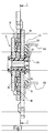
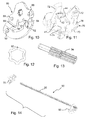
- FIG. 3 shows the fitting 5 in a cross-sectional view.
- the fitting 5 has a clip load limiter 40 connected to the driving element 27 with a clip connection that axially fixes the clip load limiter 40 to the driving element 27 with possible circumferential relative movement.
- the clip load limiter 40 in turn is connected to a handle load limiter 50, which is fixed (welded) to the shaft 7.
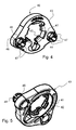
- FIGS. 4 and 5 show an embodiment of the clip load limiter 40.
- the clip load limiter 40 has an annular base part 43 with a central opening 41.
- a plurality of clip parts 44 extend into a region of the opening 41.
- Each clip part 44 has a clip element 42.
- Each clip part 44 extends from the base part 43 in a radial inward direction and curves to extend in an axial direction to the clip element 42.
- Each clip part 44 has the ability to flex allowing the clip part 42 to engage an annular recess 26 formed in the driving element 27 with a latching action.
- the clip load limiter 40 also has clip pins 46 which extend in an axial direction, away from the first fitting part 11.
- Each clip pin 46 is formed of a plurality of pin segments 47 (see FIGS. 4 and 5 ) which are connected to the base part 43 and extend to a clip part 48.
- Each of the pin segments 47 is flexible, allowing movement of the pin segments 47 so the clip pins 46 clip into openings 56 of the handle load limiter 50.
- the angle of each clip part 48 facilitates the radial movement of the pin segments 47 as the clip pin 46 moves into a respective opening 56 and beyond the surface of the handle load limiter 50. This clip connection can be seen in FIGS. 8 and 9 .
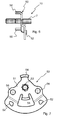
- FIG. 6 shows the handle load limiter 50 fixed to the shaft 7.
- the handle load limiter 50 has a planar part 51 with the openings 56 which receive the clip pins 46.
- Planar part 51 also includes an opening 53 which receives the transmission bar 7.
- Flanges 54 and 58 extend in a direction away from first fitting part 11, at right angles with respect to the planar part 51.
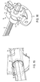
- Two cam parts 52 form a cam arrangement which interacts with fitting part recesses 16.
- Each recess 16 has a recess surface 36 with end surfaces 38. Based on the position of the cam parts 52, the cam arrangement extends into the recesses 16.
- the end surfaces 38 provide stop faces which limit the movement of the cam parts 52.
- the invention provides a fitting 5 with an end stop feature based on the clip load limiter 40 and the handle load limiter 50 fixed to the transmission bar 7.
- a shaft assembly 10 is provided with the handle load limiter 50 fixed (welded) to the transmission bar 7 as shown in FIG. 10 .
- the clip load limiter 40 is connected to the driving element 27 of the recliner fitting 5 by the clip elements 42.
- the shaft assembly 10 is inserted trough the driving element 27.
- the transmission bar 7 and the driving element 27 are toothed to provide a torque-proof connection.
- the two clip-pins 46 of the clip load limiter 40 clip into the two openings 56 of the handle load limiter 50 and are fixed to the shaft and fix the relative position of the shaft 7.
- the cam arrangement interacts with the recesses 16 of the recliner fitting 5. These recesses 16 are formed in the first fitting part 11, at the back side (handle side) of bearing segments 15. If the passenger actuates the hand lever 9, the first cam 52 hits the end surface wall 38 of one of the recesses 16, before the load is improperly high ( FIG. 9 ). This avoids application of excessive loads to the recliner fitting. Without an end stop the inner mechanism of the recliner can be destroyed, e.g. the eccentric 25 may be subjected to an over-twist. If the hand lever is not actuated, the other of the two cams 52 hits another end surface wall 38 of another recess 16. This defines the angle of the non-used hand lever 9 ( FIG. 8 ).
- FIGS. 10 through 17 show features of the second embodiment of a fitting 60 according to the invention.
- the fitting 60 has a locking structure (locking device) which is essentially the same as fittings 5 with a first fitting part 11 with an interior surface forming bearing segments 15 and an outer surface with recesses 16. Each recess 16 has a recess surface 36 with end surfaces 38 which is as shown in FIGS 8 and 9 .
- the fitting 60 includes a clip load limiter 70 and a handle load limiter 80 with a modified design.
- the clip load limiter 70 is provided which is similar to the clip load limiter 40.
- the clip load limiter 70 further includes handle return spring guide surfaces 72 which support the path of the handle return guide spring 62 ( FIG. 17 ).
- the clip load limiter 70 also includes an alignment projection 74 for engaging, in alignment, receiving slot 84 of the handle load limiter 80.
- the clip load limiter 70 includes heat stakes 76 which are deformed by heating to fix the stakes 76 of the clip load limiter 70 in the openings 86 on the handle load limiter 80.
- FIG. 14 shows a shaft sub assembly 90 with the clip load limiter 70 positioned for connection according to the second embodiment.
- the shaft sub assembly 90 is made up of a tube 92 which is welded to handle interface shaft 94 and handle load limiter 80.
- the weld 96 is a tube to plate spline weld 96 as shown in FIG. 15 .
- FIG. 14 also shows the position of the clip load limiter 70 as it is moved onto the shaft 92 and then positioned for heat staking the clip load limiter 70 to the handle load limiter 80 to form the final shaft assembly 98 as shown in FIG. 16 .
- the clip load limiter 70 has a central opening 41 with clip elements 42 extending from an annular base part 73 to clip parts 44.
- the clip parts 44 are received in the annular recess 26 formed in the driving element 27 with a latching action.
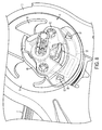
- FIG. 17 shows the fitting 60 in an assembled state, along with the handle return guide spring 62.
- the guide spring 62 is connected to the second fitting part 12 and is coursed around the handle interface shaft 94 with the guide spring 62 supported and guided via guide surfaces 72.
- the guide spring 62 extends around the handle interface shaft 94 by about 1 3/4 turns and engages around handle load limiter 80 and reverses direction to be seated in a spring connection interface in the form of a groove 88 (see FIG. 10 ).
- the spring 62 acts to move the handle to a non-use position, namely it returns the handle to a non-use position after use.
- the stop action provided by the two cams 52 of the handle load limiter 80 interacting with the end surfaces 38 interacting with the recess 16 is the same as described above with reference to FIGS 8 and 9 .
- the stop action provided in the use position prevents an over twisting of the eccentric 25. This avoids a transmission of high loads to the locking structure.
- the stop action provided in the non-use position defines the angle of the hand lever 9 in the non-use position.
Landscapes
- Engineering & Computer Science (AREA)
- Aviation & Aerospace Engineering (AREA)
- Transportation (AREA)
- Mechanical Engineering (AREA)
- Seats For Vehicles (AREA)
- Chairs For Special Purposes, Such As Reclining Chairs (AREA)
Priority Applications (1)
| Application Number | Priority Date | Filing Date | Title |
|---|---|---|---|
| PL12757991T PL2683576T3 (pl) | 2011-03-11 | 2012-03-09 | Fotel pojazdu i łącznik odchylający do fotela pojazdu |
Applications Claiming Priority (2)
| Application Number | Priority Date | Filing Date | Title |
|---|---|---|---|
| US13/045,883 US8616648B2 (en) | 2011-03-11 | 2011-03-11 | Vehicle seat and recliner fitting for vehicle seat |
| PCT/US2012/028516 WO2012125465A2 (en) | 2011-03-11 | 2012-03-09 | Vehicle seat and recliner fitting for vehicle seat |
Publications (3)
| Publication Number | Publication Date |
|---|---|
| EP2683576A2 EP2683576A2 (en) | 2014-01-15 |
| EP2683576A4 EP2683576A4 (en) | 2014-10-29 |
| EP2683576B1 true EP2683576B1 (en) | 2015-11-04 |
Family
ID=46794862
Family Applications (1)
| Application Number | Title | Priority Date | Filing Date |
|---|---|---|---|
| EP12757991.0A Active EP2683576B1 (en) | 2011-03-11 | 2012-03-09 | Vehicle seat and recliner fitting for vehicle seat |
Country Status (5)
| Country | Link |
|---|---|
| US (1) | US8616648B2 (pl) |
| EP (1) | EP2683576B1 (pl) |
| CN (1) | CN103702862B (pl) |
| PL (1) | PL2683576T3 (pl) |
| WO (1) | WO2012125465A2 (pl) |
Families Citing this family (17)
| Publication number | Priority date | Publication date | Assignee | Title |
|---|---|---|---|---|
| CA2711966C (en) * | 2008-01-17 | 2016-05-17 | Fisher Dynamics Corporation | Round recliner mechanism |
| DE102013210688B4 (de) | 2013-04-05 | 2022-03-03 | Keiper Seating Mechanisms Co., Ltd. | Beschlagsystem für einen fahrzeugsitz und fahrzeugsitz |
| JP6167792B2 (ja) * | 2013-09-19 | 2017-07-26 | アイシン精機株式会社 | 車両用シートリフター装置 |
| JP6191358B2 (ja) * | 2013-09-19 | 2017-09-06 | アイシン精機株式会社 | ハンドル戻し装置及び車両用シートリフター装置 |
| DE102014202986B4 (de) * | 2013-11-28 | 2024-01-04 | Keiper Seating Mechanisms Co., Ltd. | Beschlagsystem für einen Fahrzeugsitz |
| EP3113975B1 (en) | 2014-03-07 | 2021-03-03 | Adient Luxembourg Holding S.à r.l. | Vehicle seat recliner assembly |
| FR3024080B1 (fr) * | 2014-07-22 | 2017-06-23 | Faurecia Sieges Automobile | Dispositif de reglage angulaire pour siege de vehicule |
| US9731633B2 (en) | 2015-07-21 | 2017-08-15 | Lear Corporation | Recliner mechanism |
| US9873357B1 (en) | 2017-01-03 | 2018-01-23 | Lear Corporation | Recliner mechanism |
| DE202017101471U1 (de) * | 2017-03-14 | 2017-04-11 | Kemmann & Koch Gmbh & Co. Kg | Gelenkbeschlag insbesondere für Möbel |
| CA3011300C (en) * | 2017-09-08 | 2020-12-15 | Gianfranco Costantino | Adjustment device for adjusting the inclination of the backrest of a seat of a vehicle |
| US10611273B2 (en) * | 2017-10-09 | 2020-04-07 | Faurecia Automotive Seating, Llc | Recliner system for a vehicle seat |
| US10787102B2 (en) * | 2018-09-10 | 2020-09-29 | Lear Corporation | Recliner mechanism |
| US11142103B2 (en) * | 2019-01-17 | 2021-10-12 | Fisher & Company, Incorporated | Cross member for seat recliner assembly |
| DE102019104712A1 (de) | 2019-02-25 | 2020-08-27 | Brose Fahrzeugteile SE & Co. Kommanditgesellschaft, Coburg | Rastbeschlag für einen Fahrzeugsitz |
| CN113320452B (zh) * | 2020-02-28 | 2023-08-04 | 博泽科堡汽车零件欧洲两合公司 | 车辆、车辆座椅及其调角器布置 |
| EP4210998B1 (en) * | 2020-09-14 | 2025-12-24 | KEIPER Seating Mechanisms Co., Ltd. | Adjustment fitting for a vehicle seat, and vehicle seat |
Family Cites Families (13)
| Publication number | Priority date | Publication date | Assignee | Title |
|---|---|---|---|---|
| DE19904300C1 (de) * | 1999-01-28 | 2000-08-03 | Keiper Gmbh & Co | Rastbeschlag für einen Fahrzeugsitz |
| DE10064474B4 (de) * | 2000-12-22 | 2004-04-08 | Keiper Gmbh & Co. Kg | Betätigungsvorrichtung für einen Fahrzeugsitz-Einsteller |
| DE10253054B4 (de) * | 2002-11-14 | 2007-01-18 | Keiper Gmbh & Co.Kg | Beschlag für einen Fahrzeugsitz |
| KR20050084790A (ko) * | 2002-12-21 | 2005-08-29 | 카이퍼 게엠베하 운트 코. 카게 | 차량 의자 조정 기구용, 미끄럼 부재를 포함하는 구동장치 |
| DE10335869A1 (de) * | 2003-08-06 | 2005-03-17 | Keiper Gmbh & Co. Kg | Beschlag für einen Fahrzeugsitz |
| US7100987B2 (en) * | 2004-08-31 | 2006-09-05 | Dura Global Technologies, Inc. | Reclining vehicle seat hinge assembly |
| KR100923944B1 (ko) * | 2007-08-16 | 2009-10-29 | 주식회사다스 | 차량 시트용 리클라이닝장치 |
| FR2920713B1 (fr) * | 2007-09-12 | 2010-03-12 | Faurecia Sieges Automobile | Mecanisme de reglage d'inclinaison de siege de vehicule automobile |
| US8153258B2 (en) * | 2007-10-10 | 2012-04-10 | Ford Global Technologies, Llc | Molded assembly having a reduced tendency to squeak and a method of manufacturing the assembly |
| JP5332170B2 (ja) * | 2007-10-16 | 2013-11-06 | アイシン精機株式会社 | 車両用シートリクライニング装置 |
| CA2711966C (en) * | 2008-01-17 | 2016-05-17 | Fisher Dynamics Corporation | Round recliner mechanism |
| FR2928881B1 (fr) * | 2008-03-18 | 2010-04-09 | Faurecia Sieges Automobile | Mecanisme d'articulation et siege de vehicule comportant un tel mecanisme |
| JP5189879B2 (ja) * | 2008-04-01 | 2013-04-24 | デルタ工業株式会社 | シートのリクライニング装置 |
-
2011
- 2011-03-11 US US13/045,883 patent/US8616648B2/en active Active
-
2012
- 2012-03-09 PL PL12757991T patent/PL2683576T3/pl unknown
- 2012-03-09 CN CN201280006826.8A patent/CN103702862B/zh active Active
- 2012-03-09 WO PCT/US2012/028516 patent/WO2012125465A2/en not_active Ceased
- 2012-03-09 EP EP12757991.0A patent/EP2683576B1/en active Active
Also Published As
| Publication number | Publication date |
|---|---|
| WO2012125465A3 (en) | 2013-11-28 |
| CN103702862A (zh) | 2014-04-02 |
| CN103702862B (zh) | 2016-01-20 |
| WO2012125465A2 (en) | 2012-09-20 |
| US8616648B2 (en) | 2013-12-31 |
| EP2683576A2 (en) | 2014-01-15 |
| PL2683576T3 (pl) | 2016-03-31 |
| EP2683576A4 (en) | 2014-10-29 |
| US20120228915A1 (en) | 2012-09-13 |
Similar Documents
| Publication | Publication Date | Title |
|---|---|---|
| EP2683576B1 (en) | Vehicle seat and recliner fitting for vehicle seat | |
| US8720999B2 (en) | Fitting for a vehicle seat | |
| US8256843B2 (en) | Vehicle seat reclining device | |
| US7878593B2 (en) | Anti back drive device for a seat recliner | |
| KR100840404B1 (ko) | 차량 좌석용 힌지 기구 및 그 힌지 기구를 구비한 좌석 | |
| JP5694569B2 (ja) | 車両シート用継手 | |
| US8746796B2 (en) | Anti-backdrive for continuous disc recliner | |
| KR101373199B1 (ko) | 자동차 시트용 피팅 | |
| US20120169105A1 (en) | Fitting for a vehicle seat | |
| JP5712294B2 (ja) | 車両シート用継手 | |
| US20030020306A1 (en) | Motor vehicle seat adapted to receive a safety belt | |
| KR101586205B1 (ko) | 차량 시트용 피팅 및 차량 시트 | |
| KR101579059B1 (ko) | 차량 시트용 피팅 및 차량 시트 | |
| KR101427567B1 (ko) | 웨지를 갖는 차량용 리클라이너 | |
| KR20120050394A (ko) | 차량 시트를 위한 조절 메커니즘 | |
| CN101277842A (zh) | 用于车座的配件 | |
| JP2006506114A (ja) | 車両座席用の取り付け具 | |
| JP2008546594A (ja) | 自動開放防止のための安全装置を備えたロック/解除機構 | |
| EP1806072A1 (en) | Reclining device | |
| JP5865518B2 (ja) | 車両シート用継手及び車両シート | |
| US10144329B2 (en) | Headrest | |
| WO2008130075A1 (en) | Recliner assembly |
Legal Events
| Date | Code | Title | Description |
|---|---|---|---|
| PUAI | Public reference made under article 153(3) epc to a published international application that has entered the european phase |
Free format text: ORIGINAL CODE: 0009012 |
|
| AK | Designated contracting states |
Kind code of ref document: A2 Designated state(s): AL AT BE BG CH CY CZ DE DK EE ES FI FR GB GR HR HU IE IS IT LI LT LU LV MC MK MT NL NO PL PT RO RS SE SI SK SM TR |
|
| AX | Request for extension of the european patent |
Extension state: BA ME |
|
| 17P | Request for examination filed |
Effective date: 20140528 |
|
| RBV | Designated contracting states (corrected) |
Designated state(s): AL AT BE BG CH CY CZ DE DK EE ES FI FR GB GR HR HU IE IS IT LI LT LU LV MC MK MT NL NO PL PT RO RS SE SI SK SM TR |
|
| RAP1 | Party data changed (applicant data changed or rights of an application transferred) |
Owner name: JOHNSON CONTROLS COMPONENTS GMBH & CO. KG |
|
| A4 | Supplementary search report drawn up and despatched |
Effective date: 20140929 |
|
| RIC1 | Information provided on ipc code assigned before grant |
Ipc: B60N 2/235 20060101AFI20140923BHEP |
|
| DAX | Request for extension of the european patent (deleted) | ||
| GRAP | Despatch of communication of intention to grant a patent |
Free format text: ORIGINAL CODE: EPIDOSNIGR1 |
|
| INTG | Intention to grant announced |
Effective date: 20150805 |
|
| GRAS | Grant fee paid |
Free format text: ORIGINAL CODE: EPIDOSNIGR3 |
|
| GRAA | (expected) grant |
Free format text: ORIGINAL CODE: 0009210 |
|
| AK | Designated contracting states |
Kind code of ref document: B1 Designated state(s): AL AT BE BG CH CY CZ DE DK EE ES FI FR GB GR HR HU IE IS IT LI LT LU LV MC MK MT NL NO PL PT RO RS SE SI SK SM TR |
|
| REG | Reference to a national code |
Ref country code: GB Ref legal event code: FG4D |
|
| REG | Reference to a national code |
Ref country code: CH Ref legal event code: EP |
|
| REG | Reference to a national code |
Ref country code: AT Ref legal event code: REF Ref document number: 758939 Country of ref document: AT Kind code of ref document: T Effective date: 20151115 |
|
| REG | Reference to a national code |
Ref country code: IE Ref legal event code: FG4D |
|
| REG | Reference to a national code |
Ref country code: DE Ref legal event code: R096 Ref document number: 602012012189 Country of ref document: DE |
|
| REG | Reference to a national code |
Ref country code: NL Ref legal event code: MP Effective date: 20151104 |
|
| REG | Reference to a national code |
Ref country code: LT Ref legal event code: MG4D |
|
| REG | Reference to a national code |
Ref country code: AT Ref legal event code: MK05 Ref document number: 758939 Country of ref document: AT Kind code of ref document: T Effective date: 20151104 |
|
| REG | Reference to a national code |
Ref country code: FR Ref legal event code: PLFP Year of fee payment: 5 |
|
| PG25 | Lapsed in a contracting state [announced via postgrant information from national office to epo] |
Ref country code: NO Free format text: LAPSE BECAUSE OF FAILURE TO SUBMIT A TRANSLATION OF THE DESCRIPTION OR TO PAY THE FEE WITHIN THE PRESCRIBED TIME-LIMIT Effective date: 20160204 Ref country code: IS Free format text: LAPSE BECAUSE OF FAILURE TO SUBMIT A TRANSLATION OF THE DESCRIPTION OR TO PAY THE FEE WITHIN THE PRESCRIBED TIME-LIMIT Effective date: 20160304 Ref country code: IT Free format text: LAPSE BECAUSE OF FAILURE TO SUBMIT A TRANSLATION OF THE DESCRIPTION OR TO PAY THE FEE WITHIN THE PRESCRIBED TIME-LIMIT Effective date: 20151104 Ref country code: ES Free format text: LAPSE BECAUSE OF FAILURE TO SUBMIT A TRANSLATION OF THE DESCRIPTION OR TO PAY THE FEE WITHIN THE PRESCRIBED TIME-LIMIT Effective date: 20151104 Ref country code: NL Free format text: LAPSE BECAUSE OF FAILURE TO SUBMIT A TRANSLATION OF THE DESCRIPTION OR TO PAY THE FEE WITHIN THE PRESCRIBED TIME-LIMIT Effective date: 20151104 Ref country code: HR Free format text: LAPSE BECAUSE OF FAILURE TO SUBMIT A TRANSLATION OF THE DESCRIPTION OR TO PAY THE FEE WITHIN THE PRESCRIBED TIME-LIMIT Effective date: 20151104 Ref country code: LT Free format text: LAPSE BECAUSE OF FAILURE TO SUBMIT A TRANSLATION OF THE DESCRIPTION OR TO PAY THE FEE WITHIN THE PRESCRIBED TIME-LIMIT Effective date: 20151104 |
|
| PG25 | Lapsed in a contracting state [announced via postgrant information from national office to epo] |
Ref country code: RS Free format text: LAPSE BECAUSE OF FAILURE TO SUBMIT A TRANSLATION OF THE DESCRIPTION OR TO PAY THE FEE WITHIN THE PRESCRIBED TIME-LIMIT Effective date: 20151104 Ref country code: LV Free format text: LAPSE BECAUSE OF FAILURE TO SUBMIT A TRANSLATION OF THE DESCRIPTION OR TO PAY THE FEE WITHIN THE PRESCRIBED TIME-LIMIT Effective date: 20151104 Ref country code: SE Free format text: LAPSE BECAUSE OF FAILURE TO SUBMIT A TRANSLATION OF THE DESCRIPTION OR TO PAY THE FEE WITHIN THE PRESCRIBED TIME-LIMIT Effective date: 20151104 Ref country code: GR Free format text: LAPSE BECAUSE OF FAILURE TO SUBMIT A TRANSLATION OF THE DESCRIPTION OR TO PAY THE FEE WITHIN THE PRESCRIBED TIME-LIMIT Effective date: 20160205 Ref country code: FI Free format text: LAPSE BECAUSE OF FAILURE TO SUBMIT A TRANSLATION OF THE DESCRIPTION OR TO PAY THE FEE WITHIN THE PRESCRIBED TIME-LIMIT Effective date: 20151104 Ref country code: PT Free format text: LAPSE BECAUSE OF FAILURE TO SUBMIT A TRANSLATION OF THE DESCRIPTION OR TO PAY THE FEE WITHIN THE PRESCRIBED TIME-LIMIT Effective date: 20160304 Ref country code: AT Free format text: LAPSE BECAUSE OF FAILURE TO SUBMIT A TRANSLATION OF THE DESCRIPTION OR TO PAY THE FEE WITHIN THE PRESCRIBED TIME-LIMIT Effective date: 20151104 |
|
| REG | Reference to a national code |
Ref country code: SK Ref legal event code: T3 Ref document number: E 20288 Country of ref document: SK |
|
| REG | Reference to a national code |
Ref country code: DE Ref legal event code: R097 Ref document number: 602012012189 Country of ref document: DE |
|
| PG25 | Lapsed in a contracting state [announced via postgrant information from national office to epo] |
Ref country code: RO Free format text: LAPSE BECAUSE OF FAILURE TO SUBMIT A TRANSLATION OF THE DESCRIPTION OR TO PAY THE FEE WITHIN THE PRESCRIBED TIME-LIMIT Effective date: 20151104 Ref country code: BE Free format text: LAPSE BECAUSE OF NON-PAYMENT OF DUE FEES Effective date: 20160331 Ref country code: EE Free format text: LAPSE BECAUSE OF FAILURE TO SUBMIT A TRANSLATION OF THE DESCRIPTION OR TO PAY THE FEE WITHIN THE PRESCRIBED TIME-LIMIT Effective date: 20151104 Ref country code: DK Free format text: LAPSE BECAUSE OF FAILURE TO SUBMIT A TRANSLATION OF THE DESCRIPTION OR TO PAY THE FEE WITHIN THE PRESCRIBED TIME-LIMIT Effective date: 20151104 Ref country code: SM Free format text: LAPSE BECAUSE OF FAILURE TO SUBMIT A TRANSLATION OF THE DESCRIPTION OR TO PAY THE FEE WITHIN THE PRESCRIBED TIME-LIMIT Effective date: 20151104 |
|
| PLBE | No opposition filed within time limit |
Free format text: ORIGINAL CODE: 0009261 |
|
| STAA | Information on the status of an ep patent application or granted ep patent |
Free format text: STATUS: NO OPPOSITION FILED WITHIN TIME LIMIT |
|
| 26N | No opposition filed |
Effective date: 20160805 |
|
| PG25 | Lapsed in a contracting state [announced via postgrant information from national office to epo] |
Ref country code: LU Free format text: LAPSE BECAUSE OF FAILURE TO SUBMIT A TRANSLATION OF THE DESCRIPTION OR TO PAY THE FEE WITHIN THE PRESCRIBED TIME-LIMIT Effective date: 20160309 Ref country code: MC Free format text: LAPSE BECAUSE OF FAILURE TO SUBMIT A TRANSLATION OF THE DESCRIPTION OR TO PAY THE FEE WITHIN THE PRESCRIBED TIME-LIMIT Effective date: 20151104 |
|
| REG | Reference to a national code |
Ref country code: CH Ref legal event code: PL |
|
| GBPC | Gb: european patent ceased through non-payment of renewal fee |
Effective date: 20160309 |
|
| PG25 | Lapsed in a contracting state [announced via postgrant information from national office to epo] |
Ref country code: SI Free format text: LAPSE BECAUSE OF FAILURE TO SUBMIT A TRANSLATION OF THE DESCRIPTION OR TO PAY THE FEE WITHIN THE PRESCRIBED TIME-LIMIT Effective date: 20151104 |
|
| REG | Reference to a national code |
Ref country code: IE Ref legal event code: MM4A |
|
| PG25 | Lapsed in a contracting state [announced via postgrant information from national office to epo] |
Ref country code: BE Free format text: LAPSE BECAUSE OF FAILURE TO SUBMIT A TRANSLATION OF THE DESCRIPTION OR TO PAY THE FEE WITHIN THE PRESCRIBED TIME-LIMIT Effective date: 20151104 |
|
| PG25 | Lapsed in a contracting state [announced via postgrant information from national office to epo] |
Ref country code: IE Free format text: LAPSE BECAUSE OF NON-PAYMENT OF DUE FEES Effective date: 20160309 Ref country code: CH Free format text: LAPSE BECAUSE OF NON-PAYMENT OF DUE FEES Effective date: 20160331 Ref country code: LI Free format text: LAPSE BECAUSE OF NON-PAYMENT OF DUE FEES Effective date: 20160331 Ref country code: GB Free format text: LAPSE BECAUSE OF NON-PAYMENT OF DUE FEES Effective date: 20160309 |
|
| REG | Reference to a national code |
Ref country code: DE Ref legal event code: R081 Ref document number: 602012012189 Country of ref document: DE Owner name: KEIPER SEATING MECHANISMS CO., LTD., CN Free format text: FORMER OWNER: JOHNSON CONTROLS COMPONENTS GMBH & CO. KG, 67657 KAISERSLAUTERN, DE Ref country code: DE Ref legal event code: R081 Ref document number: 602012012189 Country of ref document: DE Owner name: ADIENT LUXEMBOURG HOLDING S.A R.L., LU Free format text: FORMER OWNER: JOHNSON CONTROLS COMPONENTS GMBH & CO. KG, 67657 KAISERSLAUTERN, DE Ref country code: DE Ref legal event code: R081 Ref document number: 602012012189 Country of ref document: DE Owner name: ADIENT LUXEMBOURG HOLDING S.A.R.L., LU Free format text: FORMER OWNER: JOHNSON CONTROLS COMPONENTS GMBH & CO. KG, 67657 KAISERSLAUTERN, DE |
|
| REG | Reference to a national code |
Ref country code: FR Ref legal event code: PLFP Year of fee payment: 6 |
|
| PGFP | Annual fee paid to national office [announced via postgrant information from national office to epo] |
Ref country code: PL Payment date: 20170308 Year of fee payment: 6 Ref country code: CZ Payment date: 20170220 Year of fee payment: 6 Ref country code: SK Payment date: 20170308 Year of fee payment: 6 |
|
| PG25 | Lapsed in a contracting state [announced via postgrant information from national office to epo] |
Ref country code: MT Free format text: LAPSE BECAUSE OF FAILURE TO SUBMIT A TRANSLATION OF THE DESCRIPTION OR TO PAY THE FEE WITHIN THE PRESCRIBED TIME-LIMIT Effective date: 20151104 |
|
| REG | Reference to a national code |
Ref country code: DE Ref legal event code: R081 Ref document number: 602012012189 Country of ref document: DE Owner name: KEIPER SEATING MECHANISMS CO., LTD., CN Free format text: FORMER OWNER: ADIENT LUXEMBOURG HOLDING S.A.R.L., LUXEMBOURG, LU Ref country code: DE Ref legal event code: R081 Ref document number: 602012012189 Country of ref document: DE Owner name: ADIENT LUXEMBOURG HOLDING S.A R.L., LU Free format text: FORMER OWNER: ADIENT LUXEMBOURG HOLDING S.A.R.L., LUXEMBOURG, LU |
|
| REG | Reference to a national code |
Ref country code: FR Ref legal event code: PLFP Year of fee payment: 7 |
|
| PG25 | Lapsed in a contracting state [announced via postgrant information from national office to epo] |
Ref country code: HU Free format text: LAPSE BECAUSE OF FAILURE TO SUBMIT A TRANSLATION OF THE DESCRIPTION OR TO PAY THE FEE WITHIN THE PRESCRIBED TIME-LIMIT; INVALID AB INITIO Effective date: 20120309 Ref country code: CY Free format text: LAPSE BECAUSE OF FAILURE TO SUBMIT A TRANSLATION OF THE DESCRIPTION OR TO PAY THE FEE WITHIN THE PRESCRIBED TIME-LIMIT Effective date: 20151104 |
|
| PG25 | Lapsed in a contracting state [announced via postgrant information from national office to epo] |
Ref country code: MK Free format text: LAPSE BECAUSE OF FAILURE TO SUBMIT A TRANSLATION OF THE DESCRIPTION OR TO PAY THE FEE WITHIN THE PRESCRIBED TIME-LIMIT Effective date: 20151104 Ref country code: TR Free format text: LAPSE BECAUSE OF FAILURE TO SUBMIT A TRANSLATION OF THE DESCRIPTION OR TO PAY THE FEE WITHIN THE PRESCRIBED TIME-LIMIT Effective date: 20151104 Ref country code: MT Free format text: LAPSE BECAUSE OF FAILURE TO SUBMIT A TRANSLATION OF THE DESCRIPTION OR TO PAY THE FEE WITHIN THE PRESCRIBED TIME-LIMIT Effective date: 20160331 |
|
| PG25 | Lapsed in a contracting state [announced via postgrant information from national office to epo] |
Ref country code: BG Free format text: LAPSE BECAUSE OF FAILURE TO SUBMIT A TRANSLATION OF THE DESCRIPTION OR TO PAY THE FEE WITHIN THE PRESCRIBED TIME-LIMIT Effective date: 20151104 |
|
| PG25 | Lapsed in a contracting state [announced via postgrant information from national office to epo] |
Ref country code: AL Free format text: LAPSE BECAUSE OF FAILURE TO SUBMIT A TRANSLATION OF THE DESCRIPTION OR TO PAY THE FEE WITHIN THE PRESCRIBED TIME-LIMIT Effective date: 20151104 |
|
| PG25 | Lapsed in a contracting state [announced via postgrant information from national office to epo] |
Ref country code: CZ Free format text: LAPSE BECAUSE OF NON-PAYMENT OF DUE FEES Effective date: 20180309 |
|
| REG | Reference to a national code |
Ref country code: SK Ref legal event code: MM4A Ref document number: E 20288 Country of ref document: SK Effective date: 20180309 |
|
| PG25 | Lapsed in a contracting state [announced via postgrant information from national office to epo] |
Ref country code: SK Free format text: LAPSE BECAUSE OF NON-PAYMENT OF DUE FEES Effective date: 20180309 |
|
| PG25 | Lapsed in a contracting state [announced via postgrant information from national office to epo] |
Ref country code: PL Free format text: LAPSE BECAUSE OF NON-PAYMENT OF DUE FEES Effective date: 20180309 |
|
| REG | Reference to a national code |
Ref country code: DE Ref legal event code: R082 Ref document number: 602012012189 Country of ref document: DE Representative=s name: KUTZENBERGER WOLFF & PARTNER PATENTANWALTSPART, DE Ref country code: DE Ref legal event code: R081 Ref document number: 602012012189 Country of ref document: DE Owner name: KEIPER SEATING MECHANISMS CO., LTD., CN Free format text: FORMER OWNER: ADIENT YANFENG SEATING MECHANISMS CO., LTD., SHANGHAI, CN Ref country code: DE Ref legal event code: R081 Ref document number: 602012012189 Country of ref document: DE Owner name: KEIPER SEATING MECHANISMS CO., LTD., CN Free format text: FORMER OWNER: ADIENT LUXEMBOURG HOLDING S.A R.L., LUXEMBOURG, LU Ref country code: DE Ref legal event code: R082 Ref document number: 602012012189 Country of ref document: DE Representative=s name: LIEDTKE & PARTNER PATENTANWAELTE, DE |
|
| REG | Reference to a national code |
Ref country code: DE Ref legal event code: R082 Ref document number: 602012012189 Country of ref document: DE Representative=s name: KUTZENBERGER WOLFF & PARTNER PATENTANWALTSPART, DE |
|
| PGFP | Annual fee paid to national office [announced via postgrant information from national office to epo] |
Ref country code: FR Payment date: 20251231 Year of fee payment: 15 |
|
| PGFP | Annual fee paid to national office [announced via postgrant information from national office to epo] |
Ref country code: DE Payment date: 20260102 Year of fee payment: 15 |