EP2683500B1 - Processus et dispositif de laminage de tubes dans un laminoir à plusieurs cages en train continu - Google Patents
Processus et dispositif de laminage de tubes dans un laminoir à plusieurs cages en train continu Download PDFInfo
- Publication number
- EP2683500B1 EP2683500B1 EP20120712982 EP12712982A EP2683500B1 EP 2683500 B1 EP2683500 B1 EP 2683500B1 EP 20120712982 EP20120712982 EP 20120712982 EP 12712982 A EP12712982 A EP 12712982A EP 2683500 B1 EP2683500 B1 EP 2683500B1
- Authority
- EP
- European Patent Office
- Prior art keywords
- rolling
- mandrel
- conveyor
- tube
- rolling mill
- Prior art date
- Legal status (The legal status is an assumption and is not a legal conclusion. Google has not performed a legal analysis and makes no representation as to the accuracy of the status listed.)
- Active
Links
- 238000005096 rolling process Methods 0.000 title claims description 363
- 238000000034 method Methods 0.000 title claims description 30
- 230000008569 process Effects 0.000 title claims description 29
- 238000011144 upstream manufacturing Methods 0.000 claims description 5
- 241000196324 Embryophyta Species 0.000 description 30
- 230000003247 decreasing effect Effects 0.000 description 10
- 238000009785 tube rolling Methods 0.000 description 10
- 230000007423 decrease Effects 0.000 description 7
- 230000008901 benefit Effects 0.000 description 6
- 238000000605 extraction Methods 0.000 description 6
- 238000003780 insertion Methods 0.000 description 5
- 230000037431 insertion Effects 0.000 description 5
- 230000003213 activating effect Effects 0.000 description 4
- 238000001816 cooling Methods 0.000 description 4
- 238000010438 heat treatment Methods 0.000 description 4
- 230000000717 retained effect Effects 0.000 description 4
- 230000002452 interceptive effect Effects 0.000 description 3
- 230000002829 reductive effect Effects 0.000 description 3
- 230000032258 transport Effects 0.000 description 3
- 230000001050 lubricating effect Effects 0.000 description 2
- 238000004519 manufacturing process Methods 0.000 description 2
- 238000003825 pressing Methods 0.000 description 2
- 230000002441 reversible effect Effects 0.000 description 2
- 241000220317 Rosa Species 0.000 description 1
- 230000001133 acceleration Effects 0.000 description 1
- 238000005452 bending Methods 0.000 description 1
- 230000006835 compression Effects 0.000 description 1
- 238000007906 compression Methods 0.000 description 1
- 230000001419 dependent effect Effects 0.000 description 1
- 230000001627 detrimental effect Effects 0.000 description 1
- 238000005516 engineering process Methods 0.000 description 1
- 230000002349 favourable effect Effects 0.000 description 1
- 239000012467 final product Substances 0.000 description 1
- 238000007667 floating Methods 0.000 description 1
- 230000000670 limiting effect Effects 0.000 description 1
- 238000003754 machining Methods 0.000 description 1
- 239000000463 material Substances 0.000 description 1
- 230000002028 premature Effects 0.000 description 1
- 239000000047 product Substances 0.000 description 1
- 230000003134 recirculating effect Effects 0.000 description 1
- 230000000284 resting effect Effects 0.000 description 1
- 230000008719 thickening Effects 0.000 description 1
Images


Classifications
-
- B—PERFORMING OPERATIONS; TRANSPORTING
- B21—MECHANICAL METAL-WORKING WITHOUT ESSENTIALLY REMOVING MATERIAL; PUNCHING METAL
- B21B—ROLLING OF METAL
- B21B17/00—Tube-rolling by rollers of which the axes are arranged essentially perpendicular to the axis of the work, e.g. "axial" tube-rolling
- B21B17/02—Tube-rolling by rollers of which the axes are arranged essentially perpendicular to the axis of the work, e.g. "axial" tube-rolling with mandrel, i.e. the mandrel rod contacts the rolled tube over the rod length
- B21B17/04—Tube-rolling by rollers of which the axes are arranged essentially perpendicular to the axis of the work, e.g. "axial" tube-rolling with mandrel, i.e. the mandrel rod contacts the rolled tube over the rod length in a continuous process
-
- B—PERFORMING OPERATIONS; TRANSPORTING
- B21—MECHANICAL METAL-WORKING WITHOUT ESSENTIALLY REMOVING MATERIAL; PUNCHING METAL
- B21B—ROLLING OF METAL
- B21B25/00—Mandrels for metal tube rolling mills, e.g. mandrels of the types used in the methods covered by group B21B17/00; Accessories or auxiliary means therefor ; Construction of, or alloys for, mandrels or plugs
- B21B25/02—Guides, supports, or abutments for mandrels, e.g. carriages or steadiers; Adjusting devices for mandrels
Definitions
- the present invention relates to a process and to a plant for rolling tubes in a continuous multi-stand rolling mill operating with a mandrel.
- Longitudinal multi-stand rolling mills operating with a mandrel of the known art may be conventionally grouped into various types, according to their architecture and paying special attention to the control of the rolling speed and to the speed and position of the mandrel within the tube.
- Continuous rolling mills with floating mandrel i.e. free mandrel
- free mandrel are those in which the mandrel may freely move within the tube when passing in the multi-stand rolling mill for the rolling operation, according to the friction forces which are generated between the mandrel and the inner wall of the tube.
- the mandrel accelerates as the rolling stands sequentially take hold.
- the extraction of the mandrel from the tube occurs at the end of the rolling operation, outside the rolling line, or in any event when the tail of the tube has left the last rolling stand, and therefore when the free mandrel has taken the same feeding speed as the tube.
- Very short cycle times and hence high productivity, e.g. 4-5 pieces per minute, are obtained with these types of rolling mills.
- this type of rolling mill is subject to various drawbacks.
- the mandrel acceleration causes states of compression in the tube which are detrimental to the dimensional quality and the defectiveness of the tubes, because the groove delimited by the rolling rollers is plugged (which status is conventionally referred to as “overfilling") in the first stands and is choked (which status is referred to as “underfilling”) in the finishing stands at the end of the rolling mill. Therefore, problems of rolling stability and of products with too large tolerances are encountered.
- the tube cooling over the length of the tube is uneven because the head part of the tube no longer reached by the mandrel remains hot longer right after the first rolling step, while the rear part where the mandrel is still inserted as the rolling operation continues is partly cooled by the mandrel with which it is in contact.
- a second type of rolling mill is that called “semi-retained-mandrel rolling mill", in which the mandrel is retained and fed more slowly than the tube, at the technologically favourable speed during the rolling operation.
- the mandrel is released from the retaining device while remaining within the tube and following it while it is moved away from the rolling line.
- the extraction of the mandrel from the tube occurs outside the rolling line, or in any event when the tube tail has left the last rolling stand, and therefore when the free mandrel has taken the same feeding speed as the tube.
- Very short cycle times and hence high productivity, e.g. 3-4 tubes per minute, are obtained with this type of rolling mills.
- a third type of rolling mill is that called "retained-mandrel rolling mill", which is characterized by a device for retaining the rack-and-pinion mandrel.
- the extracting device which is generally in the shape of a particular sequence of roller rolling stands, drags the tube forwards in the same direction as the rolling, while the retaining system blocks the mandrel so that it is extracted from within the tube, and it pulls it backwards towards the inlet side of the rolling mill from where it is then unloaded and put back into the classical mandrel transport cycle.
- the extracting device or rolling mill also serves the function of decreasing the outer diameter of the tube by further rolling it without the inner mandrel when this has been extracted. The cycle times are longer in this type of rolling mill and therefore it has less productivity than the previously described types: 2 tubes per minute may generally be rolled.
- the mandrel is fed at controlled speed, also called retaining speed, directed in the same motion direction as the tube, from the inlet to the outlet of the multi-stand rolling mill during the complete rolling cycle.
- the mandrel is first inserted into the hollow body at the tail, in the direction of the head of the same hollow body with motion in the same direction as the direction of the tube rolling.
- This first operation may occur in-line with the rolling axis, in this case it is called in-line insertion, or out-of-line, in this case it is called pre-insertion, as pre-inserting the mandrel into the hollow body is used to decrease the travel of the mandrel retaining devices, thus decreasing the cycle time of the rolling mill and increasing its productivity. Therefore, a limit in this technology is its low productivity, in particular for the rolling mills used for rolling small and medium tubes, e.g. those with nominal diameter less than or equal to 7" (177,8 mm).
- Another type of rolling mill is that called "retained-mandrel rolling mill” with extractor and with tube release at the end of the rolling operation, with the mandrel passing through the extractor.
- the rolling process carried out in this type of rolling mill provides that at the end of the tube rolling operation, the mandrel is immobilized by the specific retaining device while the tube is extracted from the mandrel by means of the extracting device by pulling it along the rolling line.
- the mandrel is then released from the retaining device, conveyed forwards by pressing rollers along the rolling line, and is caused to pass through the extracting device immediately after the tube and lastly unloaded downstream of the extractor to follow the circuit arranged for reusing the mandrels. Relatively short cycle times (2,5 tubes per minute) are obtained in this type of rolling mills.
- a drawback of this type of rolling mill is that the process includes conveying the mandrel, which is still very hot, by means of pressing rollers with the risk of damaging the mandrel surface.
- the mandrel retaining device in the rolling step normally of rack type, is to provide a releasing device which operates in cycle, adapted to release the mandrel after the extraction of the tube.
- a rolling mill and retained-mandrel rolling process associated thereto is disclosed in document WO2011/000819 , where after the extraction of the tube while the mandrel is still retained and the tube is transported and rolled through the extracting device without the mandrel therein, the mandrel is laterally removed from the rolling line with respect to the rolling line.
- the market requires rolling plants which allow increased flexibility of final product, i.e. are capable of rolling tubes of various lengths, with replacement operations over a minimum amount of components of the plant, which allow the tube rolling cycle time to be decreased and the overall productivity of the plant to be enhanced, which increase the quality of the finished tube or at least do not penalize it, which have a more rational structure than the plant itself, thus decreasing the production and handling cost thereof.
- longitudinal rolling mills of the above-described types are also defined according to parameters such as:
- the main object of the present invention is to carry out a process for rolling tubes in a continuous multi-stand rolling mill operating with a mandrel, which is more productive than known processes and may be implemented on rolling mills which are more affordable to build and to manage without decreasing the productivity of the rolling process.
- Another object of the invention is to provide a rolling plant for optimally implementing the above rolling process and which is affordable to manufacture and to implement.
- a rolling plant comprising a rolling mill with a plurality of rolling stands, defining a rolling axis, a rolling direction, an inlet side defined upstream of the rolling mill, an outlet side defined downstream of the rolling mill, wherein a first loading device, a first unloading device and a first mandrel conveyor are provided on the inlet side, and a second unloading device, a second loading device and a second mandrel conveyor are provided on the outlet side, said process comprising, in a rolling cycle, the following stages:
- a rolling plant for tubes of defined length adapted to implement a rolling process as described above, comprising a rolling mill incorporating a plurality of rolling stands adapted to roll a hollow body at each rolling cycle, defining a rolling axis, a rolling direction and a rolling cycle for each rolled tube, at least one mandrel adapted to cooperate with the rolling mill in said rolling at each rolling cycle, a first loading device, adapted to load the hollow body at each rolling cycle along rolling axis, a first unloading device, adapted to unload the at least one mandrel from the rolling axis, a first mandrel conveyor, adapted to grasp and to release a rear end of said at least one mandrel, arranged upstream of the rolling mill, and a second unloading device, adapted to unload the rolled tubes from the rolling axis, a second loading device adapted to load the at least one mandrel along
- the mandrel used in the rolling cycle is inserted into the hollow body in-line, but by proceeding in the opposite direction through the multi-stand rolling mill, inversely as compared to the normal operation in the retained-mandrel rolling mills, i.e. in the direction opposite to the rolling direction, by entering the last rolling mill stand with the tail end first.
- the extracting device or rolling mill may be eliminated from the plant while keeping however those advantages obtained when a retained-mandrel rolling process of known type is used.
- a further advantage directly resulting from the process of the invention is to have the possibility of rolling tubes of various lengths, in particular even shorter tubes with respect to those commonly produced today, i.e. with lengths greater than about 8-10 mm at the outlet of the multi-stand rolling mill.
- the mandrel which is used for a particular rolling cycle is loaded downstream of the rolling mill, reversely inserted into the multi-stand rolling mill by means of a mandrel conveyor, as the latter is arranged downstream of the rolling mill.
- the hollow body which is to be rolled with that particular mandrel is loaded by translating it transversally to the rolling direction and arranged along the rolling axis with respect to the inlet of the multi-stand rolling mill.
- the insertion of the mandrel continues by leaving the first stand of the multi-stand rolling mill, reversely into the hollow body, and the rear mandrel end which projects from the tail of the hollow body is finally hooked to a mandrel conveyor on the inlet side of the multi-stand rolling mill.
- said rear end of the mandrel is provided with specific tong suitable for hooking.
- the mandrel is placed in accordance with the features of the hollow body used and of the tube to be produced.
- the hollow body is then pushed into the multi-stand rolling mill by means of driven feeding rollers, while the mandrel reversely proceeds at controlled rolling speed.
- the control system of the rolling plant includes rolling the last part of the tube (tail or rear portion) in the last stand where the thickness of the tube wall is rolled, when the mandrel head is located just downstream of the stand, thus eliminating the need to use a further extracting rolling mill to extract the rolled tube from the mandrel.
- Such a point is conventionally called meeting point between mandrel and rolled tube.
- the tube moves towards the outlet of the multi-stand rolling mill while the mandrel continues moving in the opposite direction towards the inlet area of the rolling mill. Due to these relative movement kinematics between mandrel and tube, the time interval during which the already rolled tube overlaps the mandrel which is held in the inner cavity thereof is reduced. Thereby, the tube cooling is decreased, caused by the contact with the mandrel body which has a lower temperature than the tube and thus facilitating the possible subsequent rolling operation thereon in order to decrease the outer diameter without necessarily proceeding with intermediate heating.
- the tube Once the tube has been separated from the mandrel, it is stopped downstream of the multi-stand rolling mill in a position which is completely free from the volume of the rolling mill, while the mandrel used is stopped at the inlet of the rolling mill in a position in which the mandrel tip is arranged completely outside the rolling mill stands and totally free from the volume of the rolling mill.
- the mandrel used in that rolling cycle just completed is laterally removed from the rolling axis to an out-of-line position, so as to free the rolling line.
- the next hollow body is loaded from out-of-line to the rolling axis in order to start the next rolling cycle with the same previous sequence.
- Such operations of clearing the mandrel from the line at the inlet and insertion area on the line of the next hollow body may be obtained in various manners, e.g. by employing two rotating arms which operate co-ordinately.
- the tube rolled in the rolling cycle just completed, in the stationary position reached after braking, is removed from the rolling axis to out-of-line by means of various systems, e.g. by means of a rotating arm.
- the mandrel which is to be used for rolling in the next cycle is transferred from out-of-line to the rolling axis, e.g. by means of rotating arms as well.
- the movement of these two rotating arms may be coordinated in order to decrease the cycle times.
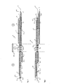
- a preferred embodiment of a rolling plant operating with a mandrel at controlled speed is shown, globally indicated by reference R, which may implement a continuous rolling process of tubes with mandrel at controlled speed and high productivity, according to the invention.
- the rolling plant defines a rolling axis X and a rolling direction 23 followed by the material to be rolled, called hollow body 39, and by the rolled tubes 40, which direction is depicted from left to right in the figures.
- the rolling direction 23 is the same in figures 1 to 6 , even if it is not indicated.
- the plant is conventionally divided into an inlet area or side 20, in which device 2 for unloading the mandrel from the rolling axis, and device 1 for loading the hollow body along rolling axis are located, in a properly called rolling area 21 in which the multi-stand rolling mill 5 is located, and in an outlet area or side 22, in which device 4 for loading the mandrel and device 3 for unloading the rolled tube from the rolling axis X are located.
- Device 1 for loading the hollow body along rolling axis is positioned at the inlet of the multi-stand rolling mill 5 and is advantageously, but not exclusively, made in the shape of a rotating arm mounted by the side of the rolling axis.
- a device 1 for loading the hollow body picks the hollow body 39 from a lateral out-of-line position and places it along the rolling axis where rollers are arranged for supporting the hollow body and the mandrel (not shown in detail in the figures as they are devices known in the art).
- Device 2 for unloading the mandrel from the rolling axis is also positioned at the inlet of the multi-stand rolling mill 5 and is advantageously, but not exclusively, made with a rotating arm mounted by the side of the rolling axis X.
- Device 2 for unloading the mandrel is mounted at the inlet of the multi-stand rolling mill 5 on the side opposite to that of device 1 for loading the hollow body with respect to the rolling axis X.
- device 2 When in operation, device 2 picks mandrel 30 which served to roll tube 40, from the rolling axis X at the end of each rolling cycle, and transports it to a lateral position outside the rolling line.
- This position forms part of a device for recirculating the mandrels used in the process which includes, in a known manner not shown in detail in the figures, operations of cooling the mandrel, the temperature of which rose due to the heat received from the tube during the rolling operation, and lubricating operations before being conveyed to the outlet side 22 of the rolling mill for employment in other rolling cycles.
- Device 3 for unloading the rolled tube 40 from the rolling axis X is positioned at the outlet of the multi-stand rolling mill 5 and is, advantageously but not exclusively, made in the shape of a rotating arm mounted by the side of the rolling axis X, which picks tube 40 at the end of rolling and transports it to a lateral position out-of-line from the rolling axis, for possible storing or for other machining or operations.
- This device 3 for unloading the tube from the rolling axis X is mounted at the outlet of the multi-stand rolling mill on the same side as device 1 for loading the hollow body, shown in the bottom section of the figures with respect to the rolling axis X.
- Device 4 for loading the mandrel along rolling axis X is positioned at the outlet of the multi-stand rolling mill 5 and is advantageously, but not exclusively, made in the shape of a rotating arm mounted by the side of the rolling axis X. When in operation, it picks mandrel 31 from a lateral out-of-line position and puts it down along rolling axis X where rollers are arranged for supporting the mandrel and the tube which forms part of conveyor 7 of the mandrel on the outlet side 22 (they are also not depicted in detail because of known art).
- Device 4 for loading the mandrel is mounted at the outlet of the multi-stand rolling mill 5 on the same side as device 2 for unloading the mandrel, shown in the top section of the figures with reference to the rolling axis X.
- the multi-stand rolling mill 5 is advantageously, but not exclusively, made as alternate stand rolling mill with two or more rollers per stand, in which the stands follow one another so that the jumps by the rollers of the odd stands along the rolling axis X correspond with the groove bottoms of the even stands and vice versa.
- the process of the invention may also be implemented by means of rolling mills of tubes of other type, without departing from the spirit of the invention.
- the mandrel conveyor 6 on the inlet side 20 essentially comprises a mandrel support device with height-adjustable rollers and a longitudinal mandrel-moving system, preferably, but not exclusively, of the rack type with motorized driving pinions.
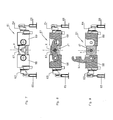
- the mandrel conveyor is also equipped with a hooking and releasing device 61 by means of which it engages the tong arranged in the rear area of the mandrel.
- the hooking and releasing device 61 is of the so-called "drawbridge" type and acts in connection with the rear tong of the mandrel.
- the closed position of the drawbridge is shown in figures 7 and 8 , while the open position is shown in figure 9 .
- Device 61 goes from a hooking position to a releasing position by means of a counter-clockwise rotation, which is considered in the depiction in the figures. Instead, the passage from releasing to hooking occurs with the clockwise rotation.
- Device 61 comprises two separate heads 68, 69 which are respectively fixed to the front end of a rack device (not shown), a lever 67, hinged on the first head 68, consisting of the drawbridge which is engaged at the other end in a slot arranged in the second head 69 and with the top part of the rear tong of the mandrel, such a lever 67 being shaped in the middle with an upside down U-shaped groove. It is also possible to arrange the elements of device 61 so as to provide the fulcrum of lever 67 arranged on head 69 and having the same functions with rotation in direction inverse to the previous variant.
- Device 61 also comprises a device 63 for controlling the rapid opening and closure of lever 67, in turn controlled by a movable cam 65.
- a device 64 for locking device 61 in closed position is controlled by a respective movable cam device 66.
- the mandrel conveyor 7 on the outlet side 22 comprises a mandrel support device consisting of height-adjustable rollers and a longitudinal mandrel-moving system, preferably, but not exclusively, of the rack type with motorized driving pinions.
- the mandrel conveyor 7 on the outlet side 22 has a drawbridge hooking and releasing device 71, in which it engages a tong of the mandrel arranged close to the head end of the mandrel.
- the hooking position of device 71 is shown in the two figures 10 and 11 , while the mandrel releasing position of the device is shown in figure 12 .
- Device 71 comprises a head 76 fixed to the front end of a rack of the outlet side of the rolling mill, a lever 77 which consists of the drawbridge, hinged onto head 76.
- the hooking and releasing device 71 is only adapted to engage the mandrel on the top part of the tong, but not on the bottom part thereof, lever 77 being equipped with an upside down U-shaped groove.
- Device 71 goes from a hooking position to a releasing position by means of a counter-clockwise rotation, which is considered in the depiction in the figures. Instead, the passage from releasing to hooking occurs with the clockwise rotation.
- Device 71 also comprises a control device 73 mounted on the rack and controlled by a movable cam 75.
- the hooking and releasing devices 61 and 71, on the inlet side 20 and on the outlet side 22, incorporated in the respective conveyors 6 and 7 thereof have the advantage that the mandrel hooking and releasing operations, which is operating in a given rolling cycle, at the head and tail, may be cyclically and quickly achieved at each cycle, unlike the hooking and releasing devices which only provide these operations in emergency cases.
- the rounding stand 10 serves the purpose of creating an approximately even clearance between mandrel and inner diameter of the tube, and may also be used as effective device for braking the tube in the last stage of the rolling cycle.
- the tube may be braked by using the rounding stand, such operation allows the cycle times and the spaces required to brake the tube at the end of rolling, to be decreased.
- Figure 2 shows a subsequent stage of the rolling process.
- mandrel 30 has been removed from the rolling line by the rotating arm 2 and is at the top side with respect to the figure, or left side with respect to the rolling line X, ready to continue undergoing other operations before returning to the outlet side 22, where it will serve for a next rolling cycle, which is not necessarily cycle n+1, as the amount of mandrels employed in the process may be large, if the operations of cooling and lubricating the mandrel are longer than the cycle time of the proper rolling.
- Rolling the hollow body 39 within the multi-stand rolling mill 5 occurs with the movement of mandrel 31 which is fed by the hooking device 61 in direction indicated by arrow L3, which is retrograde with respect to the rolling direction 23 between the hooking position P4 and the releasing position P3.
- the movement of mandrel 31 is coordinated with the movement of the hollow body 39 indicated by arrow L4, caused by the rollers of the rolling stands 12 of the rolling mill 5.
- the speed of the movement of mandrel 31 in the direction of arrow L3 is determined in such a way that the front end of mandrel 31 is located, completely rolled, at the rear end of tube 42 when the rear end of the tube leaves the last rolling stand 12, i.e. that furthest right between the stands indicated with numeral 12 in the depiction in the figures, thus defining the "meeting point".
- mandrel 31, which is completely rolled is completely extracted from the cavity of tube 42 after passing the meeting point.
- tube 42 may be made to pass through one or more rounding stands 10. This operation is optional and contributes to improving the shape of the finished tube.
- mandrel 31 which has left the inside of tube 42, is braked and positioned on the rolling line X, as shown in figure 6 , in such a position as to be outside the volume of the multi-stand rolling mill 5, so as to be removed from the rolling line at the beginning of the next rolling cycle "n+1 ".
- the rear area of mandrel 31 is released by the grip of the hooking device 61 in releasing position P3 to allow the removal thereof by rotating the rotating arm 2.
- the rolled tube 42 is ready to be removed from the rolling line X by rotating the rotating arm 3 to allow the operations to start the next rolling cycle "n+1".
Claims (11)
- Procédé de laminage d'un tube à partir d'un corps creux doté d'une cavité interne, à l'aide d'au moins un mandrin, dans lequel un équipement de laminage (R) est prévu, comprenant un laminoir (5) avec une pluralité de cages de laminage (12), définissant un axe de laminage (X), une direction de laminage (23), un côté entrée (20) défini en amont du laminoir, un côté sortie (22) défini en aval du laminoir, dans lequel un premier dispositif de chargement (1), un premier dispositif de déchargement (2) et un premier convoyeur de mandrin (6) sont prévus sur le côté entrée (20), et un second dispositif de déchargement (3), un second dispositif de chargement (4) et un second convoyeur de mandrin (7) sont prévus sur le côté sortie (22),
ledit procédé comprenant, dans un cycle de laminage, les étapes suivantes :- le chargement du corps creux (39, 41) le long de l'axe de laminage (X) depuis le côté entrée (20) au moyen dudit premier dispositif de chargement (1),- le chargement du au moins un mandrin (31, 32) le long de l'axe de laminage (X) depuis le côté sortie (22) au moyen dudit second dispositif de chargement (4) et le raccordement d'une première zone d'extrémité du au moins un mandrin (31, 32) audit second convoyeur (7),- la translation axiale du au moins un mandrin (31, 32) le long de l'axe de laminage (X) à travers le laminoir (5) et à travers la cavité interne du corps creux (39, 41),- la fixation solidaire d'une seconde zone d'extrémité du au moins un mandrin (31, 32) audit premier convoyeur (6) et le relâchement de la première zone d'extrémité du au moins un mandrin (31, 32) depuis ledit second convoyeur (7),- le laminage du corps creux (39, 41) en faisant passer celui-ci à travers des cages de laminage (12) du laminoir (5) dans la direction de laminage (23), de façon à produire un tube laminé tout en amenant simultanément le mandrin (31) par le premier convoyeur (6) dans la direction (L3) opposée à la direction de laminage (23),- l'extraction totale du mandrin (31, 32) de l'intérieur du tube laminé (40, 42) et du laminoir (5). - Procédé de laminage selon la revendication 1, dans lequel le mandrin (30, 31) est retiré de l'axe de laminage (X) au moyen du premier dispositif de déchargement (2) et est acheminé jusqu'au côté sortie (22) pour un cycle de laminage suivant.
- Procédé de laminage selon la revendication 1, dans lequel une étape d'arrondissement de tube laminé est prévue, réalisée par au moins une cage à arrondir (10).
- Procédé de laminage selon la revendication 1, dans lequel la fixation solidaire au premier convoyeur (6) et le relâchement du au moins un mandrin (31) depuis le second convoyeur (7) se produisent de façon coordonnée.
- Equipement de laminage (R) pour des tubes d'une longueur prédéfinie, adapté pour mettre en oeuvre un procédé de laminage selon la revendication 1, comprenant
un laminoir (5) incorporant une pluralité de cages de laminage (12) adapté pour laminer un corps creux (39, 41) à chaque cycle de laminage, définissant un axe de laminage (X), une direction de laminage (23) et un cycle de laminage pour chaque tube laminé,
au moins un mandrin (30, 31, 32) adapté pour coopérer avec le laminoir (5) lors dudit laminage à chaque cycle de laminage,
un premier dispositif de chargement (1), adapté pour charger le corps creux à chaque cycle de laminage le long de l'axe de laminage (X), un premier dispositif de déchargement (2), adapté pour décharger le au moins un mandrin (30, 31, 32) de l'axe de laminage (X), un premier convoyeur de mandrin (6), adapté pour saisir et relâcher une extrémité arrière dudit au moins un mandrin (30, 31, 32), agencée en amont du laminoir (5), et
un second dispositif de déchargement (3), adapté pour décharger les tubes laminés depuis l'axe de laminage (X), un second dispositif de chargement (4) adapté pour charger le au moins un mandrin (30, 31, 32) le long de l'axe de laminage (X), un second convoyeur de mandrin (7), adapté pour saisir et relâcher une extrémité avant dudit au moins un mandrin (30, 31, 32), agencée en aval du laminoir (5),
des moyens de commande de l'équipement de laminage (R) qui permettent au premier convoyeur (6) de saisir et relâcher ladite extrémité arrière du au moins un mandrin (30, 31, 32) à chaque cycle de laminage de façon coordonnée avec le relâchement et la saisie, respectivement, de ladite extrémité avant du au moins un mandrin (30, 31, 32) par le second convoyeur (7). - Equipement de laminage selon la revendication 5, dans lequel ledit laminoir (5) comprend des cages de support de mandrin (8).
- Equipement de laminage selon la revendication 6, dans lequel le premier convoyeur de mandrin (6) comprend un dispositif de support de mandrin avec des cylindres réglables en hauteur et un système de déplacement de mandrin longitudinal.
- Equipement de laminage selon la revendication 7, dans lequel le dispositif de déplacement de mandrin longitudinal comprend un dispositif de crémaillère avec des pignons d'entraînement motorisés et un dispositif d'accrochage/de relâchement de pince dans une zone arrière du mandrin.
- Equipement de laminage selon la revendication 8, dans lequel un dispositif (11) pour amener le corps creux dans le laminoir (5) est prévu.
- Equipement de laminage selon la revendication 9, dans lequel au moins une cage à arrondir (10) est prévue en aval de la dernière cage de laminage du laminoir (5).
- Equipement de laminage selon la revendication 10, dans lequel un dispositif d'arrêt de type guillotine (9) est prévu pour extraire le mandrin du tube laminé ou du corps creux dans des conditions d'urgence.
Applications Claiming Priority (2)
| Application Number | Priority Date | Filing Date | Title |
|---|---|---|---|
| IT000372A ITMI20110372A1 (it) | 2011-03-10 | 2011-03-10 | Processo di laminazione per tubi in laminatoio continuo multigabbia |
| PCT/EP2012/054087 WO2012120111A1 (fr) | 2011-03-10 | 2012-03-09 | Processus de laminage de tubes dans un laminoir à plusieurs cages en train continu |
Publications (2)
| Publication Number | Publication Date |
|---|---|
| EP2683500A1 EP2683500A1 (fr) | 2014-01-15 |
| EP2683500B1 true EP2683500B1 (fr) | 2015-05-06 |
Family
ID=43977042
Family Applications (1)
| Application Number | Title | Priority Date | Filing Date |
|---|---|---|---|
| EP20120712982 Active EP2683500B1 (fr) | 2011-03-10 | 2012-03-09 | Processus et dispositif de laminage de tubes dans un laminoir à plusieurs cages en train continu |
Country Status (9)
| Country | Link |
|---|---|
| US (1) | US9283599B2 (fr) |
| EP (1) | EP2683500B1 (fr) |
| JP (1) | JP5688476B2 (fr) |
| CN (1) | CN103442819B (fr) |
| AR (1) | AR085641A1 (fr) |
| IT (1) | ITMI20110372A1 (fr) |
| RU (1) | RU2553176C2 (fr) |
| SA (1) | SA112330330B1 (fr) |
| WO (1) | WO2012120111A1 (fr) |
Families Citing this family (6)
| Publication number | Priority date | Publication date | Assignee | Title |
|---|---|---|---|---|
| DE102013002268B4 (de) | 2013-02-12 | 2018-04-05 | Sms Group Gmbh | Walzanlage bzw. -verfahren |
| GB201516884D0 (en) * | 2015-09-23 | 2015-11-04 | Racine Marc André | Reinforced corrugated plastic sheets and products |
| US11267217B2 (en) * | 2016-08-23 | 2022-03-08 | Marc-Andre Racine | System and method for bending a hollow core sheet using rods |
| CN110369522A (zh) * | 2019-08-14 | 2019-10-25 | 广东科莱博科技有限公司 | 一种管坯推送装置及推送方法 |
| IT201900014925A1 (it) * | 2019-08-22 | 2021-02-22 | Danieli Off Mecc | Dispositivo di guida per la guida di una barra di spinta di un mandrino o per la guida di un mandrino in un processo di laminazione di corpi tubolari |
| CN112828054A (zh) * | 2020-12-28 | 2021-05-25 | 太原重工股份有限公司 | 连轧机前支撑装置 |
Family Cites Families (15)
| Publication number | Priority date | Publication date | Assignee | Title |
|---|---|---|---|---|
| NL130355C (fr) * | 1964-09-09 | |||
| FR2214533B1 (fr) * | 1973-01-23 | 1977-08-19 | Innocenti Santeustacchio Spa | |
| FR2338093A1 (fr) * | 1976-01-19 | 1977-08-12 | Vallourec | Nouveau laminoir de fabrication de tubes sans soudure et installation de fabrication de tubes sans soudure comportant un tel laminoir |
| US4037449A (en) * | 1976-07-30 | 1977-07-26 | Aetna-Standard Engineering Company | Continuous flow plug mill system |
| SU831241A1 (ru) * | 1979-10-19 | 1981-05-23 | Предприятие П/Я В-2869 | Механизм смены оправок трубопрокат-НОгО CTAHA |
| FR2469962A1 (fr) * | 1979-11-21 | 1981-05-29 | Vallourec | Procede et dispositif pour la fabrication d'un tube d'acier sans soudure par laminage a chaud sur mandrin |
| DE3333390A1 (de) * | 1983-09-13 | 1985-03-21 | Mannesmann AG, 4000 Düsseldorf | Vorrichtung zum zu- und abfuehren der dornstangen an schraeg- und laengswalzwerken |
| JPS61289905A (ja) * | 1985-06-17 | 1986-12-19 | Kawasaki Steel Corp | 継目無管の可逆延伸圧延方法および装置 |
| SU1733131A1 (ru) * | 1989-05-03 | 1992-05-15 | Днепропетровский Центр Научно-Технического Творчества "Импульс" | Способ продольной прокатки труб |
| EP1854561B1 (fr) * | 2005-02-22 | 2011-08-24 | Sumitomo Metal Industries, Ltd. | Procede de production de tuyau sans soudure |
| DE102005044777A1 (de) * | 2005-09-20 | 2007-03-29 | Sms Meer Gmbh | Verfahren und Walzwerk zur Herstellung eines nahtlosen Rohres |
| CN101214499A (zh) * | 2007-12-30 | 2008-07-09 | 太原市通泽成套设备有限公司 | 两种穿芯棒方式的三辊轧管机 |
| DE102008039454B4 (de) * | 2008-08-25 | 2011-01-27 | Sms Meer Gmbh | Verfahren zur Herstellung eines nahtlosen Stahlrohres und Walzwerk zur Durchführung des Verfahrens |
| IT1395593B1 (it) * | 2009-06-29 | 2012-10-16 | Danieli Off Mecc | Procedimento di laminazione e relativo laminatoio longitudinale multi gabbia di tipo trattenuto e continuo per corpi cavi |
| ITMI20110573A1 (it) * | 2011-04-07 | 2012-10-08 | Danieli Off Mecc | Dispositivo di convogliamento di mandrino per impianto di laminazione di tubi |
-
2011
- 2011-03-10 IT IT000372A patent/ITMI20110372A1/it unknown
-
2012
- 2012-03-07 SA SA112330330A patent/SA112330330B1/ar unknown
- 2012-03-09 AR ARP120100770A patent/AR085641A1/es active IP Right Grant
- 2012-03-09 EP EP20120712982 patent/EP2683500B1/fr active Active
- 2012-03-09 JP JP2013557110A patent/JP5688476B2/ja active Active
- 2012-03-09 US US13/416,016 patent/US9283599B2/en not_active Expired - Fee Related
- 2012-03-09 RU RU2013145374/02A patent/RU2553176C2/ru active
- 2012-03-09 CN CN201280012592.8A patent/CN103442819B/zh active Active
- 2012-03-09 WO PCT/EP2012/054087 patent/WO2012120111A1/fr active Application Filing
Also Published As
| Publication number | Publication date |
|---|---|
| SA112330330B1 (ar) | 2015-07-07 |
| WO2012120111A1 (fr) | 2012-09-13 |
| RU2553176C2 (ru) | 2015-06-10 |
| US20130061646A1 (en) | 2013-03-14 |
| ITMI20110372A1 (it) | 2012-09-11 |
| CN103442819A (zh) | 2013-12-11 |
| JP2014510640A (ja) | 2014-05-01 |
| US9283599B2 (en) | 2016-03-15 |
| EP2683500A1 (fr) | 2014-01-15 |
| CN103442819B (zh) | 2015-11-25 |
| AR085641A1 (es) | 2013-10-16 |
| RU2013145374A (ru) | 2015-04-20 |
| JP5688476B2 (ja) | 2015-03-25 |
Similar Documents
| Publication | Publication Date | Title |
|---|---|---|
| EP2683500B1 (fr) | Processus et dispositif de laminage de tubes dans un laminoir à plusieurs cages en train continu | |
| EP2694227B1 (fr) | Dispositif de transport de mandrin pour laminoir à tubes | |
| EP2519366B1 (fr) | Dispositif et procédé enrouleur / dérouleur dans une ligne de laminage de métal | |
| US8904839B2 (en) | Method of and rolling mill for making seamless steel pipe | |
| EP2448686B2 (fr) | Procédé de laminage et laminoir longitudinal correspondant à cages multiples de type continu et retenu pour corps creux | |
| US4571970A (en) | Rolling mill plant for the manufacture of seamless tubes | |
| US4289011A (en) | Continuous pipe rolling process | |
| CA1198917A (fr) | Mecanisme de centrage et de guidage des billettes a l'entree d'une presse perforatrice | |
| EP2986399B1 (fr) | Laminoir transversal intégré pour tubes sans soudure | |
| JP2007275996A (ja) | マンドレル緊急引抜装置およびマンドレル緊急引抜方法、並びにこれらを用いるマンドレルミル | |
| US1978422A (en) | Method and apparatus for the manufacture of tubes |
Legal Events
| Date | Code | Title | Description |
|---|---|---|---|
| PUAI | Public reference made under article 153(3) epc to a published international application that has entered the european phase |
Free format text: ORIGINAL CODE: 0009012 |
|
| 17P | Request for examination filed |
Effective date: 20131009 |
|
| AK | Designated contracting states |
Kind code of ref document: A1 Designated state(s): AL AT BE BG CH CY CZ DE DK EE ES FI FR GB GR HR HU IE IS IT LI LT LU LV MC MK MT NL NO PL PT RO RS SE SI SK SM TR |
|
| DAX | Request for extension of the european patent (deleted) | ||
| GRAP | Despatch of communication of intention to grant a patent |
Free format text: ORIGINAL CODE: EPIDOSNIGR1 |
|
| INTG | Intention to grant announced |
Effective date: 20141002 |
|
| GRAS | Grant fee paid |
Free format text: ORIGINAL CODE: EPIDOSNIGR3 |
|
| GRAA | (expected) grant |
Free format text: ORIGINAL CODE: 0009210 |
|
| AK | Designated contracting states |
Kind code of ref document: B1 Designated state(s): AL AT BE BG CH CY CZ DE DK EE ES FI FR GB GR HR HU IE IS IT LI LT LU LV MC MK MT NL NO PL PT RO RS SE SI SK SM TR |
|
| REG | Reference to a national code |
Ref country code: GB Ref legal event code: FG4D |
|
| REG | Reference to a national code |
Ref country code: CH Ref legal event code: EP |
|
| REG | Reference to a national code |
Ref country code: IE Ref legal event code: FG4D |
|
| REG | Reference to a national code |
Ref country code: AT Ref legal event code: REF Ref document number: 725330 Country of ref document: AT Kind code of ref document: T Effective date: 20150615 |
|
| REG | Reference to a national code |
Ref country code: DE Ref legal event code: R096 Ref document number: 602012007181 Country of ref document: DE Effective date: 20150618 |
|
| REG | Reference to a national code |
Ref country code: NL Ref legal event code: MP Effective date: 20150506 |
|
| REG | Reference to a national code |
Ref country code: LT Ref legal event code: MG4D |
|
| PG25 | Lapsed in a contracting state [announced via postgrant information from national office to epo] |
Ref country code: ES Free format text: LAPSE BECAUSE OF FAILURE TO SUBMIT A TRANSLATION OF THE DESCRIPTION OR TO PAY THE FEE WITHIN THE PRESCRIBED TIME-LIMIT Effective date: 20150506 Ref country code: FI Free format text: LAPSE BECAUSE OF FAILURE TO SUBMIT A TRANSLATION OF THE DESCRIPTION OR TO PAY THE FEE WITHIN THE PRESCRIBED TIME-LIMIT Effective date: 20150506 Ref country code: NO Free format text: LAPSE BECAUSE OF FAILURE TO SUBMIT A TRANSLATION OF THE DESCRIPTION OR TO PAY THE FEE WITHIN THE PRESCRIBED TIME-LIMIT Effective date: 20150806 Ref country code: PT Free format text: LAPSE BECAUSE OF FAILURE TO SUBMIT A TRANSLATION OF THE DESCRIPTION OR TO PAY THE FEE WITHIN THE PRESCRIBED TIME-LIMIT Effective date: 20150907 Ref country code: LT Free format text: LAPSE BECAUSE OF FAILURE TO SUBMIT A TRANSLATION OF THE DESCRIPTION OR TO PAY THE FEE WITHIN THE PRESCRIBED TIME-LIMIT Effective date: 20150506 Ref country code: HR Free format text: LAPSE BECAUSE OF FAILURE TO SUBMIT A TRANSLATION OF THE DESCRIPTION OR TO PAY THE FEE WITHIN THE PRESCRIBED TIME-LIMIT Effective date: 20150506 |
|
| PG25 | Lapsed in a contracting state [announced via postgrant information from national office to epo] |
Ref country code: IS Free format text: LAPSE BECAUSE OF FAILURE TO SUBMIT A TRANSLATION OF THE DESCRIPTION OR TO PAY THE FEE WITHIN THE PRESCRIBED TIME-LIMIT Effective date: 20150906 Ref country code: LV Free format text: LAPSE BECAUSE OF FAILURE TO SUBMIT A TRANSLATION OF THE DESCRIPTION OR TO PAY THE FEE WITHIN THE PRESCRIBED TIME-LIMIT Effective date: 20150506 Ref country code: RS Free format text: LAPSE BECAUSE OF FAILURE TO SUBMIT A TRANSLATION OF THE DESCRIPTION OR TO PAY THE FEE WITHIN THE PRESCRIBED TIME-LIMIT Effective date: 20150506 Ref country code: BG Free format text: LAPSE BECAUSE OF FAILURE TO SUBMIT A TRANSLATION OF THE DESCRIPTION OR TO PAY THE FEE WITHIN THE PRESCRIBED TIME-LIMIT Effective date: 20150806 Ref country code: GR Free format text: LAPSE BECAUSE OF FAILURE TO SUBMIT A TRANSLATION OF THE DESCRIPTION OR TO PAY THE FEE WITHIN THE PRESCRIBED TIME-LIMIT Effective date: 20150807 |
|
| PG25 | Lapsed in a contracting state [announced via postgrant information from national office to epo] |
Ref country code: DK Free format text: LAPSE BECAUSE OF FAILURE TO SUBMIT A TRANSLATION OF THE DESCRIPTION OR TO PAY THE FEE WITHIN THE PRESCRIBED TIME-LIMIT Effective date: 20150506 Ref country code: EE Free format text: LAPSE BECAUSE OF FAILURE TO SUBMIT A TRANSLATION OF THE DESCRIPTION OR TO PAY THE FEE WITHIN THE PRESCRIBED TIME-LIMIT Effective date: 20150506 |
|
| REG | Reference to a national code |
Ref country code: DE Ref legal event code: R097 Ref document number: 602012007181 Country of ref document: DE |
|
| REG | Reference to a national code |
Ref country code: AT Ref legal event code: UEP Ref document number: 725330 Country of ref document: AT Kind code of ref document: T Effective date: 20150506 |
|
| REG | Reference to a national code |
Ref country code: FR Ref legal event code: PLFP Year of fee payment: 5 |
|
| PG25 | Lapsed in a contracting state [announced via postgrant information from national office to epo] |
Ref country code: PL Free format text: LAPSE BECAUSE OF FAILURE TO SUBMIT A TRANSLATION OF THE DESCRIPTION OR TO PAY THE FEE WITHIN THE PRESCRIBED TIME-LIMIT Effective date: 20150506 Ref country code: CZ Free format text: LAPSE BECAUSE OF FAILURE TO SUBMIT A TRANSLATION OF THE DESCRIPTION OR TO PAY THE FEE WITHIN THE PRESCRIBED TIME-LIMIT Effective date: 20150506 Ref country code: SK Free format text: LAPSE BECAUSE OF FAILURE TO SUBMIT A TRANSLATION OF THE DESCRIPTION OR TO PAY THE FEE WITHIN THE PRESCRIBED TIME-LIMIT Effective date: 20150506 Ref country code: RO Free format text: LAPSE BECAUSE OF NON-PAYMENT OF DUE FEES Effective date: 20150506 |
|
| PLBE | No opposition filed within time limit |
Free format text: ORIGINAL CODE: 0009261 |
|
| STAA | Information on the status of an ep patent application or granted ep patent |
Free format text: STATUS: NO OPPOSITION FILED WITHIN TIME LIMIT |
|
| 26N | No opposition filed |
Effective date: 20160209 |
|
| PG25 | Lapsed in a contracting state [announced via postgrant information from national office to epo] |
Ref country code: SI Free format text: LAPSE BECAUSE OF FAILURE TO SUBMIT A TRANSLATION OF THE DESCRIPTION OR TO PAY THE FEE WITHIN THE PRESCRIBED TIME-LIMIT Effective date: 20150506 |
|
| PG25 | Lapsed in a contracting state [announced via postgrant information from national office to epo] |
Ref country code: BE Free format text: LAPSE BECAUSE OF FAILURE TO SUBMIT A TRANSLATION OF THE DESCRIPTION OR TO PAY THE FEE WITHIN THE PRESCRIBED TIME-LIMIT Effective date: 20150506 |
|
| PG25 | Lapsed in a contracting state [announced via postgrant information from national office to epo] |
Ref country code: MC Free format text: LAPSE BECAUSE OF FAILURE TO SUBMIT A TRANSLATION OF THE DESCRIPTION OR TO PAY THE FEE WITHIN THE PRESCRIBED TIME-LIMIT Effective date: 20150506 Ref country code: LU Free format text: LAPSE BECAUSE OF FAILURE TO SUBMIT A TRANSLATION OF THE DESCRIPTION OR TO PAY THE FEE WITHIN THE PRESCRIBED TIME-LIMIT Effective date: 20160309 |
|
| REG | Reference to a national code |
Ref country code: CH Ref legal event code: PL |
|
| GBPC | Gb: european patent ceased through non-payment of renewal fee |
Effective date: 20160309 |
|
| REG | Reference to a national code |
Ref country code: IE Ref legal event code: MM4A |
|
| PG25 | Lapsed in a contracting state [announced via postgrant information from national office to epo] |
Ref country code: CH Free format text: LAPSE BECAUSE OF NON-PAYMENT OF DUE FEES Effective date: 20160331 Ref country code: IE Free format text: LAPSE BECAUSE OF NON-PAYMENT OF DUE FEES Effective date: 20160309 Ref country code: GB Free format text: LAPSE BECAUSE OF NON-PAYMENT OF DUE FEES Effective date: 20160309 Ref country code: LI Free format text: LAPSE BECAUSE OF NON-PAYMENT OF DUE FEES Effective date: 20160331 |
|
| REG | Reference to a national code |
Ref country code: FR Ref legal event code: PLFP Year of fee payment: 6 |
|
| PG25 | Lapsed in a contracting state [announced via postgrant information from national office to epo] |
Ref country code: SE Free format text: LAPSE BECAUSE OF FAILURE TO SUBMIT A TRANSLATION OF THE DESCRIPTION OR TO PAY THE FEE WITHIN THE PRESCRIBED TIME-LIMIT Effective date: 20150506 Ref country code: NL Free format text: LAPSE BECAUSE OF FAILURE TO SUBMIT A TRANSLATION OF THE DESCRIPTION OR TO PAY THE FEE WITHIN THE PRESCRIBED TIME-LIMIT Effective date: 20150506 |
|
| PG25 | Lapsed in a contracting state [announced via postgrant information from national office to epo] |
Ref country code: MT Free format text: LAPSE BECAUSE OF FAILURE TO SUBMIT A TRANSLATION OF THE DESCRIPTION OR TO PAY THE FEE WITHIN THE PRESCRIBED TIME-LIMIT Effective date: 20150506 |
|
| REG | Reference to a national code |
Ref country code: FR Ref legal event code: PLFP Year of fee payment: 7 |
|
| PG25 | Lapsed in a contracting state [announced via postgrant information from national office to epo] |
Ref country code: CY Free format text: LAPSE BECAUSE OF FAILURE TO SUBMIT A TRANSLATION OF THE DESCRIPTION OR TO PAY THE FEE WITHIN THE PRESCRIBED TIME-LIMIT Effective date: 20150506 Ref country code: SM Free format text: LAPSE BECAUSE OF FAILURE TO SUBMIT A TRANSLATION OF THE DESCRIPTION OR TO PAY THE FEE WITHIN THE PRESCRIBED TIME-LIMIT Effective date: 20150506 Ref country code: HU Free format text: LAPSE BECAUSE OF FAILURE TO SUBMIT A TRANSLATION OF THE DESCRIPTION OR TO PAY THE FEE WITHIN THE PRESCRIBED TIME-LIMIT; INVALID AB INITIO Effective date: 20120309 |
|
| PG25 | Lapsed in a contracting state [announced via postgrant information from national office to epo] |
Ref country code: MT Free format text: LAPSE BECAUSE OF FAILURE TO SUBMIT A TRANSLATION OF THE DESCRIPTION OR TO PAY THE FEE WITHIN THE PRESCRIBED TIME-LIMIT Effective date: 20160331 Ref country code: TR Free format text: LAPSE BECAUSE OF FAILURE TO SUBMIT A TRANSLATION OF THE DESCRIPTION OR TO PAY THE FEE WITHIN THE PRESCRIBED TIME-LIMIT Effective date: 20150506 Ref country code: MK Free format text: LAPSE BECAUSE OF FAILURE TO SUBMIT A TRANSLATION OF THE DESCRIPTION OR TO PAY THE FEE WITHIN THE PRESCRIBED TIME-LIMIT Effective date: 20150506 |
|
| PG25 | Lapsed in a contracting state [announced via postgrant information from national office to epo] |
Ref country code: AL Free format text: LAPSE BECAUSE OF FAILURE TO SUBMIT A TRANSLATION OF THE DESCRIPTION OR TO PAY THE FEE WITHIN THE PRESCRIBED TIME-LIMIT Effective date: 20150506 |
|
| PGFP | Annual fee paid to national office [announced via postgrant information from national office to epo] |
Ref country code: FR Payment date: 20230327 Year of fee payment: 12 Ref country code: AT Payment date: 20230221 Year of fee payment: 12 |
|
| PGFP | Annual fee paid to national office [announced via postgrant information from national office to epo] |
Ref country code: IT Payment date: 20230321 Year of fee payment: 12 |
|
| P01 | Opt-out of the competence of the unified patent court (upc) registered |
Effective date: 20230511 |
|
| PGFP | Annual fee paid to national office [announced via postgrant information from national office to epo] |
Ref country code: AT Payment date: 20240221 Year of fee payment: 13 |
|
| PGFP | Annual fee paid to national office [announced via postgrant information from national office to epo] |
Ref country code: DE Payment date: 20240327 Year of fee payment: 13 |