EP2683003A1 - Battery, in particular lead battery - Google Patents
Battery, in particular lead battery Download PDFInfo
- Publication number
- EP2683003A1 EP2683003A1 EP12174627.5A EP12174627A EP2683003A1 EP 2683003 A1 EP2683003 A1 EP 2683003A1 EP 12174627 A EP12174627 A EP 12174627A EP 2683003 A1 EP2683003 A1 EP 2683003A1
- Authority
- EP
- European Patent Office
- Prior art keywords
- spacer
- electrode plate
- electrode plates
- spacers
- fußrahmenleiste
- Prior art date
- Legal status (The legal status is an assumption and is not a legal conclusion. Google has not performed a legal analysis and makes no representation as to the accuracy of the status listed.)
- Granted
Links
Images


Classifications
-
- H—ELECTRICITY
- H01—ELECTRIC ELEMENTS
- H01M—PROCESSES OR MEANS, e.g. BATTERIES, FOR THE DIRECT CONVERSION OF CHEMICAL ENERGY INTO ELECTRICAL ENERGY
- H01M10/00—Secondary cells; Manufacture thereof
- H01M10/04—Construction or manufacture in general
- H01M10/0486—Frames for plates or membranes
-
- H—ELECTRICITY
- H01—ELECTRIC ELEMENTS
- H01M—PROCESSES OR MEANS, e.g. BATTERIES, FOR THE DIRECT CONVERSION OF CHEMICAL ENERGY INTO ELECTRICAL ENERGY
- H01M50/00—Constructional details or processes of manufacture of the non-active parts of electrochemical cells other than fuel cells, e.g. hybrid cells
- H01M50/50—Current conducting connections for cells or batteries
- H01M50/543—Terminals
- H01M50/547—Terminals characterised by the disposition of the terminals on the cells
- H01M50/55—Terminals characterised by the disposition of the terminals on the cells on the same side of the cell
-
- H—ELECTRICITY
- H01—ELECTRIC ELEMENTS
- H01M—PROCESSES OR MEANS, e.g. BATTERIES, FOR THE DIRECT CONVERSION OF CHEMICAL ENERGY INTO ELECTRICAL ENERGY
- H01M10/00—Secondary cells; Manufacture thereof
- H01M10/04—Construction or manufacture in general
- H01M10/049—Processes for forming or storing electrodes in the battery container
-
- H—ELECTRICITY
- H01—ELECTRIC ELEMENTS
- H01M—PROCESSES OR MEANS, e.g. BATTERIES, FOR THE DIRECT CONVERSION OF CHEMICAL ENERGY INTO ELECTRICAL ENERGY
- H01M10/00—Secondary cells; Manufacture thereof
- H01M10/06—Lead-acid accumulators
- H01M10/12—Construction or manufacture
- H01M10/14—Assembling a group of electrodes or separators
-
- H—ELECTRICITY
- H01—ELECTRIC ELEMENTS
- H01M—PROCESSES OR MEANS, e.g. BATTERIES, FOR THE DIRECT CONVERSION OF CHEMICAL ENERGY INTO ELECTRICAL ENERGY
- H01M10/00—Secondary cells; Manufacture thereof
- H01M10/06—Lead-acid accumulators
- H01M10/12—Construction or manufacture
- H01M10/16—Suspending or supporting electrodes or groups of electrodes in the case
-
- H—ELECTRICITY
- H01—ELECTRIC ELEMENTS
- H01M—PROCESSES OR MEANS, e.g. BATTERIES, FOR THE DIRECT CONVERSION OF CHEMICAL ENERGY INTO ELECTRICAL ENERGY
- H01M4/00—Electrodes
- H01M4/02—Electrodes composed of, or comprising, active material
- H01M4/64—Carriers or collectors
- H01M4/70—Carriers or collectors characterised by shape or form
- H01M4/76—Containers for holding the active material, e.g. tubes, capsules
- H01M4/765—Tubular type or pencil type electrodes; tubular or multitubular sheaths or covers of insulating material for said tubular-type electrodes
-
- H—ELECTRICITY
- H01—ELECTRIC ELEMENTS
- H01M—PROCESSES OR MEANS, e.g. BATTERIES, FOR THE DIRECT CONVERSION OF CHEMICAL ENERGY INTO ELECTRICAL ENERGY
- H01M50/00—Constructional details or processes of manufacture of the non-active parts of electrochemical cells other than fuel cells, e.g. hybrid cells
- H01M50/40—Separators; Membranes; Diaphragms; Spacing elements inside cells
- H01M50/46—Separators, membranes or diaphragms characterised by their combination with electrodes
-
- Y—GENERAL TAGGING OF NEW TECHNOLOGICAL DEVELOPMENTS; GENERAL TAGGING OF CROSS-SECTIONAL TECHNOLOGIES SPANNING OVER SEVERAL SECTIONS OF THE IPC; TECHNICAL SUBJECTS COVERED BY FORMER USPC CROSS-REFERENCE ART COLLECTIONS [XRACs] AND DIGESTS
- Y02—TECHNOLOGIES OR APPLICATIONS FOR MITIGATION OR ADAPTATION AGAINST CLIMATE CHANGE
- Y02E—REDUCTION OF GREENHOUSE GAS [GHG] EMISSIONS, RELATED TO ENERGY GENERATION, TRANSMISSION OR DISTRIBUTION
- Y02E60/00—Enabling technologies; Technologies with a potential or indirect contribution to GHG emissions mitigation
- Y02E60/10—Energy storage using batteries
-
- Y—GENERAL TAGGING OF NEW TECHNOLOGICAL DEVELOPMENTS; GENERAL TAGGING OF CROSS-SECTIONAL TECHNOLOGIES SPANNING OVER SEVERAL SECTIONS OF THE IPC; TECHNICAL SUBJECTS COVERED BY FORMER USPC CROSS-REFERENCE ART COLLECTIONS [XRACs] AND DIGESTS
- Y02—TECHNOLOGIES OR APPLICATIONS FOR MITIGATION OR ADAPTATION AGAINST CLIMATE CHANGE
- Y02P—CLIMATE CHANGE MITIGATION TECHNOLOGIES IN THE PRODUCTION OR PROCESSING OF GOODS
- Y02P70/00—Climate change mitigation technologies in the production process for final industrial or consumer products
- Y02P70/50—Manufacturing or production processes characterised by the final manufactured product
Definitions
- the invention relates to an accumulator, in particular in the embodiment as a lead-acid battery, with a plurality of positive and negative electrode plates, which are arranged alternately and spaced apart leaving a respective gap space to each other.
- Accumulators of the type mentioned above have a plurality of electrode plates, via positive electrode plates on the one hand and negative electrode plates on the other hand.
- the electrode plates are arranged in an accumulator housing which is filled with an electrolyte.
- the housing has an opening which, in the final assembled state of the accumulator, is closed in a fluid-tight manner by means of a cover.
- the positive and negative electrode plates are arranged alternately within the accumulator housing.
- the two outer electrode plates are each negative electrode plates.
- the spaced arrangement of adjacent electrode plates is required to permit electrolyte circulation.
- a separator between two adjacent electrode plates is provided to avoid electrical contact.
- separator plate separating two electrode plates from each other, which carries ribs on one of its two sides of action.
- These ribs which can also be referred to as spacer ribs, serve for the spaced arrangement of two electrode plates with simultaneous formation of a separator. It is usually provided that the separator and the ribs provided by the separator are integrally formed.
- constructions have also become known from the prior art, according to which mesh fabrics are used for spacing formation.
- the positive electrode plate may be formed in this case preferably as a bag.
- This embodiment is particularly advantageous for production reasons, since the positive electrode plates of an accumulator can be prefabricated and equipped on the one hand with a separator and on the other hand with a mesh grid serving as a spacer.
- An equipped with such a designed positive electrode plates accumulator is for example from the EP 2 312 673 A1 known.
- an accumulator of the type mentioned is proposed with the invention, which is characterized in that the positive electrode plates are each equipped with a spacer, each spacer is formed in two parts and each have a head side of the respective electrode plate formed headboard and a Having foot side of the respective electrode plates formed foot part.
- the accumulator according to the invention has trained in particular Spacer for the spaced arrangement of adjacent electrode plates. It is provided according to the invention that the positive electrode plates are equipped with a corresponding spacer.
- each spacer is formed in two parts and has a head part on the one hand and a foot part on the other. In the final assembled state, the head part of the spacer is formed on the head side and the foot part of the spacer is formed on the foot side of the respective positive electrode plate.
- each spacer is formed as separate components.
- a free gap space is thus created between adjacent electrode plates.
- this free gap space is defined defined in terms of its gap, in accordance with the geometric dimensions of the spacer, that is, the headboard and footboard.
- the spacer formed from the head part and foot part is preferably arranged in the context of accumulator production in an automated assembly process on the respective electrode plate. In this way, prepared positive electrode plates are to be arranged to form a finished accumulator with a corresponding number of negative electrode plates within a Akkumulatorgereheatuses.
- Head and foot of the spacer according to the invention are formed of an electrically non-conductive material, such as plastic.
- the spacer according to the invention supports in the final assembled state of the accumulator adjacent electrode plates on the one hand in the head area and on the other hand in the foot area from each other. As a result, a secure and permanently dimensionally accurate spacing is achieved.
- the spacer according to the invention does not extend in contrast, for example, to previously known network constructions not over the entire effective surface of adjacent electrode plates, but is limited to the foot or head area.
- the construction according to the invention on the one hand helps to keep clear the gap space formed between adjacent electrode plates.
- the accumulator production proves to be much less expensive and therefore more economical due to the construction according to the invention. In contrast to the prior art, it is no longer necessary in particular to introduce electrode plates with pocket formation in mains hoses.
- the design of a largely free gap space between two adjacent electrode plates offers the advantage, moreover, that an electrolyte in the gap is less flow-impeded and therefore can circulate more freely.
- the gap size is reduced and thus the size of the accumulator can be varied more freely. It is particularly possible to achieve a more compact design due to a reduced gap size.
- the support of two adjacent electrode plates in the foot and in the head area achieved with the spacer configuration according to the invention also makes it possible to also handle the electrode plates resting on one another during the production process.
- the embodiment according to the invention has shown that the gap space between two adjacent electrode plates can be formed without a separator.
- the design according to the invention makes it possible to completely dispense with a separator provided between two electrode plates. This is particularly because a defined gap with simultaneous electrical decoupling is created by the head-side and foot-side support of adjacent electrode plates. A full-surface coverage of the active surfaces of an electrode plate with a separator is not necessary in this respect. The manufacturing process is hereby simplified once again.
- the head part of a spacer is designed according to a special feature of the invention in the manner of a hood. This is slipped in the final assembled state on the header of the respective electrode plate.
- corresponding latching devices can be provided which ensure a secure hold of the hood designed as a head part of the electrode plate.
- the hood has a passage opening for the lug of the electrode plate, via which flag in a conventional manner an electrical contact can be made.
- the design of the head part as a hood also provides the advantage of a protective effect with respect to the header of the electrode plate.
- the embodiment of the invention provides a remedy here, since a protection of the head strips is achieved by the head parts designed as a hood, which precludes any Eigenwachsungen.
- the risk of short circuits due to coalescing headers do not exist in a spacer according to the invention, so that the construction of the invention also proves to be advantageous in that it contributes to the reliability of the battery.
- spacers may be formed integrally with the contemplatzigenance according to a first alternative of the invention.
- the spacers are designed as components separate from the foot frame bar, each of which has a connecting portion for the preferably detachable arrangement on the foot frame bar.
- Theticianllenold is made of plastic and forms in a conventional manner the foot end of a positive electrode plate.
- the spacers of the foot can be formed as an integral part of this approachingrahmenance. However, an embodiment which according to the spacers are designed as separate components for rapidly serveenance and to arrange the final design of the accumulator on this is preferred.
- the number of spacers can optionally be specified, as well as their relative position on the treatingrahmenance. It is preferred to provide at least two spacers per active surface of an electrode plate. In this way, a safe and dimensionally accurate spacing of two adjacent electrode plates is achieved. Depending on the size of the electrode plates, more than two spacers may be provided.
- a peripheral configuration is preferred. With more than two spacers, a substantially equal spacing between successive spacers is preferred.
- the spacers have extensions acting on both large surfaces of the electrode plates.
- This embodiment has the advantage that a spacer provides for both large surfaces, that is, to both active surfaces of an electrode plate extending extensions, so that it requires the arrangement of only two spacers to a proper spacing both in terms of a large area and in terms of the other large area to reach.
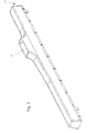
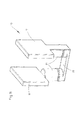
- An accumulator 1 is in a purely schematic representation in FIG. 1 shown. He has positive electrode plates 2 on the one hand and negative electrode plates 3 on the other hand, which are arranged alternately and spaced apart leaving a respective gap space 5 to each other. This structure of a rechargeable battery 1 is known per se from the prior art.
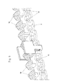
- FIG. 12 shows a schematic perspective view of a positive electrode plate 2 according to the invention.
- the positive electrode plate 2 has a header 16 which connects a plurality of individual bars 14 together.
- the header 16 is equipped with a flag 12.
- the rods 14 are disposed within a tube pocket 13 of a nonwoven material. From the pocket 13, the active mass 15 is further included, which surrounds the rods 14.
- a spacer 6, as in the FIGS. 1 to 11 is shown.
- the spacer 6 has, as in particular the illustration after FIG. 1 can recognize, via a head part 7 on the one hand and a foot part 8 on the other.
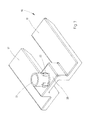
- the head part 7 is designed in the manner of a hood, which is slipped over the head strip 16 of the electrode plate 2. This factual context arises in particular from the presentation below FIG. 2 ,
- FIG. 4 and 5 can be seen in different views designed as a hood head part 7.
- the headliner 16th In the final assembled state is through the hood, the headliner 16th completely covered.
- the supported by the header 16 flag 12 which protrudes through a designated passage opening of the hood, in particular the representation according to FIG. 2 lets recognize.
- the foot part 8 of the spacer 6 is formed in the embodiment shown by a predominantlyrahmenance 9 on the one hand and by spacers 10 arranged thereon on the other.
- FIG. 6 lets recognize the principlellenance 9 according to the invention in a schematic perspective view.
- the subjectrahmenance 9 has anchor elements 18. These anchor elements 18 serve to fix the contemplatllenance 9 on the tube pocket 13.
- the satisfiedrahmenance 9 also has openings 19. These openings 19 serve the arrangement of spacers 10 on the subjectrahmenance 9th
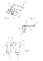
- Such a spacer 10 is according to a first embodiment in FIG. 7 shown in a schematic perspective view.
- the spacer 10 has a base 20 which carries a connecting portion 21.
- this connecting portion 21 is formed in the manner of a bolt corresponding to the openings 19 provided in theticianrahmenance 9.
- the connecting portion 21 has projections 22.
- a spacer 10 has, starting from its base 20 via extensions 17. In the final assembled state, these extensions 17 are arranged for Abstandschwahrung between two adjacent electrode plates 2 and 3, as shown in the illustration FIG. 1 lets recognize.
- FIGS. 8, 9 and 10 An alternative embodiment with respect to the spacer 10 show the FIGS. 8, 9 and 10 , According to this embodiment, a cross-sectionally shaped connecting section 21 is used. This cross-sectional configuration ensures a rotationally secure arrangement of the spacer 10 on a primallenance 9.
- the extensions 17 each with a recess 23 trained.
- the projections 7 also carry in their base 20 opposite end portion an inclined surface 24. This inclined surface 24 simplifies in the final assembled state of a positive electrode plate threading an adjacent negative electrode plate.
- FIG. 11 Another embodiment of the spacer 10 is shown in FIG. 11 shown.
- the spacer 10 has two extensions 17, wherein each extension 17 comes into effect on one of the large surfaces of the electrode plate 2.
- FIG. 2 lets recognize a positive electrode plate 2 according to the invention in the final assembled state.
- the spacer 6 comprises on the one hand the head part 7 and on the other hand the foot part 8.
- the foot part 8 in turn consists of the solicitrahmenance 9 and the spacers arranged thereon 10.
- There are four spacers 10 are provided, two on one side of the positive electrode plate 2 and two on the in FIG. 2 not shown, other side of the positive electrode plate 2. Instead of four such in FIG. 2 shown spacers 10 could also according to two spacers 10 of the embodiment FIG. 11 be used.
Landscapes
- Chemical & Material Sciences (AREA)
- Chemical Kinetics & Catalysis (AREA)
- Electrochemistry (AREA)
- General Chemical & Material Sciences (AREA)
- Engineering & Computer Science (AREA)
- Manufacturing & Machinery (AREA)
- Secondary Cells (AREA)
Abstract
Description
Die Erfindung betrifft einen Akkumulator, insbesondere in der Ausgestaltung als Bleiakkumulator, mit einer Mehrzahl von positiven und negativen Elektrodenplatten, die einander abwechselnd und unter Belassung eines jeweiligen Spaltraums beabstandet zueinander angeordnet sind.The invention relates to an accumulator, in particular in the embodiment as a lead-acid battery, with a plurality of positive and negative electrode plates, which are arranged alternately and spaced apart leaving a respective gap space to each other.
Ein Akkumulator der eingangs genannten Art ist aus dem Stand der Technik an sich gut bekannt, weshalb es eines gesonderten druckschriftlichen Nachweises an dieser Stelle nicht bedarf.An accumulator of the type mentioned is well known from the prior art, which is why it does not require a separate documentary proof at this point.
Akkumulatoren der eingangs genannten Art verfügen über eine Mehrzahl von Elektrodenplatten, und zwar über positive Elektrodenplatten einerseits und negative Elektrodenplatten andererseits. Die Elektrodenplatten sind in einem Akkumulatorgehäuse angeordnet, das mit einem Elektrolyten befüllt ist. Zur Bestückung des Gehäuses verfügt dieses über eine Öffnung, die im endmontierten Zustand des Akkumulators mittels eines Deckels bevorzugter Weise fluiddicht verschlossen ist.Accumulators of the type mentioned above have a plurality of electrode plates, via positive electrode plates on the one hand and negative electrode plates on the other hand. The electrode plates are arranged in an accumulator housing which is filled with an electrolyte. For equipping the housing, the housing has an opening which, in the final assembled state of the accumulator, is closed in a fluid-tight manner by means of a cover.
Die positiven und negativen Elektrodenplatten sind innerhalb des Akkumulatorgehäuses einander abwechselnd angeordnet. Dabei ist bevorzugter Weise vorgesehen, dass es sich bei den beiden äußeren Elektrodenplatten um jeweils negative Elektrodenplatten handelt.The positive and negative electrode plates are arranged alternately within the accumulator housing. In this case, it is preferably provided that the two outer electrode plates are each negative electrode plates.
Die beabstandete Anordnung benachbarter Elektrodenplatten ist erforderlich, damit eine Elektrolytzirkulation gestattet ist. Dabei ist zur Vermeidung einer elektrischen Kontaktierung ein Separator zwischen zwei benachbarten Elektrodenplatten vorgesehen.The spaced arrangement of adjacent electrode plates is required to permit electrolyte circulation. In this case, a separator between two adjacent electrode plates is provided to avoid electrical contact.
Zum Zwecke der beanstandeten Anordnung ist es aus dem Stand der Technik bekannt geworden, ein zwei Elektrodenplatten voneinander separierendes Separatorblatt zu verwenden, das auf einer seiner beiden Wirkseiten Rippen trägt. Diese auch als Abstandsrippen zu bezeichnenden Rippen dienen der beabstandeten Anordnung zweier Elektrodenplatten unter gleichzeitiger Ausbildung eines Separators. Es ist dabei in der Regel vorgesehen, dass der Separator und die vom Separator bereitgestellten Rippen einstückig ausgebildet sind.For the purpose of the disputed arrangement, it has become known from the prior art to use a separator plate separating two electrode plates from each other, which carries ribs on one of its two sides of action. These ribs, which can also be referred to as spacer ribs, serve for the spaced arrangement of two electrode plates with simultaneous formation of a separator. It is usually provided that the separator and the ribs provided by the separator are integrally formed.
Aus dem Stand der Technik sind auch Konstruktionen bekannt geworden, wonach zur Abstandsausbildung Netzgewebe zum Einsatz kommen. In diesem Fall ist es besonders bevorzugt, die positive Elektrodenplatte innerhalb eines getaschten Netzschlauches anzuordnen. Auch der Separator kann in diesem Fall bevorzugter Weise als Tasche ausgebildet sein. Diese Ausgestaltung ist insbesondere aus produktionstechnischen Gründen von Vorteil, da die positiven Elektrodenplatten eines Akkumulators vorkonfektioniert ausgebildet und einerseits mit einem Separator und andererseits mit einem als Abstandshalter dienenden Netzgitter ausgerüstet werden können. Ein mit solch ausgestalteten positiven Elektrodenplatten ausgerüsteter Akkumulator ist beispielsweise aus der
Obgleich sich vorbeschriebene Akkumulatorkonstruktionen im alltäglichen Praxiseinsatz bewährt haben, besteht Verbesserungsbedarf, insbesondere mit Blick auf eine noch weiter vereinfachte Herstellung. Darüber hinaus soll die Funktionssicherheit des Akkumulators erhöht werden. Es ist deshalb die Aufgabe der Erfindung, einen Akkumulator der eingangs genannten Art dahingehend weiterzuentwickeln, dass insbesondere eine vereinfachte Handhabung während der Akkumulatorherstellung erreicht ist.Although the above-described accumulator designs have proven their worth in everyday practical use, there is a need for improvement, in particular with regard to an even more simplified production. In addition, the reliability of the battery should be increased. It is therefore an object of the invention to further develop an accumulator of the type mentioned in that in particular a simplified handling during the accumulator production is achieved.
Zur Lösung dieser Aufgabe wird mit der Erfindung ein Akkumulator der eingangs genannten Art vorgeschlagen, der sich dadurch auszeichnet, dass die positiven Elektrodenplatten jeweils mit einem Abstandshalter ausgerüstet sind, wobei ein jeder Abstandshalter zweiteilig ausgebildet ist und jeweils ein kopfseitig der jeweiligen Elektrodenplatte ausgebildetes Kopfteil sowie ein fußseitig der jeweiligen Elektrodenplatten ausgebildetes Fußteil aufweist.To solve this problem, an accumulator of the type mentioned is proposed with the invention, which is characterized in that the positive electrode plates are each equipped with a spacer, each spacer is formed in two parts and each have a head side of the respective electrode plate formed headboard and a Having foot side of the respective electrode plates formed foot part.
Der Akkumulator nach der Erfindung verfügt über im Besonderen ausgebildete Abstandshalter zur beabstandeten Anordnung benachbarter Elektrodenplatten. Es ist nach der Erfindung vorgesehen, dass die positiven Elektrodenplatten mit einem entsprechenden Abstandshalter ausgerüstet sind. Dabei ist ein jeder Abstandshalter zweiteilig ausgebildet und verfügt über ein Kopfteil einerseits und ein Fußteil anderseits. Im endmontierten Zustand ist das Kopfteil des Abstandshalters kopfseitig und das Fußteil des Abstandshalters fußseitig der jeweiligen positiven Elektrodenplatte ausgebildet.The accumulator according to the invention has trained in particular Spacer for the spaced arrangement of adjacent electrode plates. It is provided according to the invention that the positive electrode plates are equipped with a corresponding spacer. In this case, each spacer is formed in two parts and has a head part on the one hand and a foot part on the other. In the final assembled state, the head part of the spacer is formed on the head side and the foot part of the spacer is formed on the foot side of the respective positive electrode plate.
Das Kopfteil und das Fußteil eines jeden Abstandshalters sind als jeweils separate Bauteile ausgebildet. Im endmontierten Zustand eines Akkumulators wird so ein freier Spaltraum zwischen benachbarten Elektrodenplatten geschaffen. Dabei ist dieser freie Spaltraum hinsichtlich seines Spaltmaßes definiert festgelegt, und zwar in Entsprechung der geometrischen Abmessungen des Abstandshalters, das heißt dessen Kopfteil und Fußteil.The head part and the foot part of each spacer are formed as separate components. In the final assembled state of a rechargeable battery, a free gap space is thus created between adjacent electrode plates. In this case, this free gap space is defined defined in terms of its gap, in accordance with the geometric dimensions of the spacer, that is, the headboard and footboard.
Der aus Kopfteil und Fußteil gebildete Abstandshalter wird bevorzugter Weise im Rahmen der Akkumulatorherstellung in einem automatisierten Montageverfahren an der jeweiligen Elektrodenplatte angeordnet. In dieser Weise vorbereitete positive Elektrodenplatten sind zur Ausbildung eines endfertigen Akkumulators mit einer entsprechenden Anzahl an negativen Elektrodenplatten innerhalb eines Akkumulatorgehäuses anzuordnen.The spacer formed from the head part and foot part is preferably arranged in the context of accumulator production in an automated assembly process on the respective electrode plate. In this way, prepared positive electrode plates are to be arranged to form a finished accumulator with a corresponding number of negative electrode plates within a Akkumulatorgehäuses.
Kopf- und Fußteil des erfindungsgemäßen Abstandshalters sind aus einem elektrisch nicht leitenden Material, beispielsweise Kunststoff gebildet.Head and foot of the spacer according to the invention are formed of an electrically non-conductive material, such as plastic.
Der erfindungsgemäße Abstandshalter stützt im endmontierten Zustand des Akkumulators einander benachbarte Elektrodenplatten einerseits im Kopfbereich sowie andererseits im Fußbereich gegenüber einander ab. Hierdurch wird eine sichere und dauerhaft maßhaltige Beabstandung erreicht. Dabei erstreckt sich der erfindungsgemäße Abstandshalter im Unterschied beispielsweise zu vorbekannten Netzkonstruktionen nicht über die gesamte Wirkoberfläche benachbarter Elektrodenplatten, sondern ist auf deren Fuß- bzw. Kopfbereich beschränkt. Damit hilft die erfindungsgemäße Konstruktion zum einen, den zwischen benachbarten Elektrodenplatten ausgebildeten Spaltraum freizuhalten. Zum anderen erweist sich die Akkumulatorherstellung aufgrund der erfindungsgemäßen Konstruktion als sehr viel weniger aufwendig und damit wirtschaftlicher. Im Unterschied zum Stand der Technik ist es insbesondere nicht mehr erforderlich, Elektrodenplatten unter Taschenbildung in Netzschläuche einzubringen.The spacer according to the invention supports in the final assembled state of the accumulator adjacent electrode plates on the one hand in the head area and on the other hand in the foot area from each other. As a result, a secure and permanently dimensionally accurate spacing is achieved. In this case, the spacer according to the invention does not extend in contrast, for example, to previously known network constructions not over the entire effective surface of adjacent electrode plates, but is limited to the foot or head area. Thus, the construction according to the invention on the one hand helps to keep clear the gap space formed between adjacent electrode plates. On the other hand, the accumulator production proves to be much less expensive and therefore more economical due to the construction according to the invention. In contrast to the prior art, it is no longer necessary in particular to introduce electrode plates with pocket formation in mains hoses.
Die Ausgestaltung eines weitestgehend freien Spaltraums zwischen zwei benachbarten Elektrodenplatten bietet im Übrigen den Vorteil, dass ein im Spaltraum befindlicher Elektrolyt weniger strömungsbehindert ist und deshalb freier zirkulieren kann. In der Konsequenz kann im Unterschied zum Stand der Technik das Spaltmaß verringert und damit die Baugröße des Akkumulators freier variiert werden. Es ist insbesondere möglich, aufgrund eines verringerten Spaltmaßes eine kompaktere Bauform zu erreichen.The design of a largely free gap space between two adjacent electrode plates offers the advantage, moreover, that an electrolyte in the gap is less flow-impeded and therefore can circulate more freely. As a consequence, in contrast to the prior art, the gap size is reduced and thus the size of the accumulator can be varied more freely. It is particularly possible to achieve a more compact design due to a reduced gap size.
Die mit der erfindungsgemäßen Abstandshalterausgestaltung erreichte Abstützung zweier benachbarter Elektrodenplatten sowohl im Fuß- als auch im Kopfbereich gestattet es zudem, die Elektrodenplatten während des Herstellungsprozesses auch aufeinander aufliegend zu handhaben.The support of two adjacent electrode plates in the foot and in the head area achieved with the spacer configuration according to the invention also makes it possible to also handle the electrode plates resting on one another during the production process.
Die erfindungsgemäße Ausgestaltung hat im Übrigen ergeben, dass der Spaltraum zwischen zwei benachbarten Elektrodenplatten separatorfrei ausgebildet werden kann. Die erfindungsgemäße Ausgestaltung erlaubt es indes, im Unterschied zu aus dem Stand der Technik bekannten Konstruktionen auf einen zwischen zwei Elektrodenplatten vorgesehenen Separator vollends verzichten zu können. Dies insbesondere deshalb, weil durch die kopfseitige und fußseitige Abstützung benachbarter Elektrodenplatten ein definiertes Spaltmaß bei gleichzeitiger elektrischer Entkopplung geschaffen ist. Eine vollflächige Belegung der Wirkoberflächen einer Elektrodenplatte mit einem Separator ist insoweit nicht mehr erforderlich. Der Herstellungsprozess wird hierdurch noch einmal vereinfacht.Incidentally, the embodiment according to the invention has shown that the gap space between two adjacent electrode plates can be formed without a separator. However, in contrast to structures known from the prior art, the design according to the invention makes it possible to completely dispense with a separator provided between two electrode plates. This is particularly because a defined gap with simultaneous electrical decoupling is created by the head-side and foot-side support of adjacent electrode plates. A full-surface coverage of the active surfaces of an electrode plate with a separator is not necessary in this respect. The manufacturing process is hereby simplified once again.
Das Kopfteil eines Abstandshalters ist gemäß einem besonderen Merkmal der Erfindung nach Art einer Haube ausgebildet. Diese ist im endmontierten Zustand über die Kopfleiste der jeweiligen Elektrodenplatte gestülpt. Zum Zwecke einer sicheren Anordnung können entsprechende Rasteinrichtungen vorgesehen sein, die einen sicheren Halt des als Haube ausgebildeten Kopfteils an der Elektrodenplatte gewährleisten. Dabei verfügt die Haube über eine Durchtrittsöffnung für die Fahne der Elektrodenplatte, über welche Fahne in an sich bekannter Weise eine elektrische Kontaktierung erfolgen kann.The head part of a spacer is designed according to a special feature of the invention in the manner of a hood. This is slipped in the final assembled state on the header of the respective electrode plate. For the purpose of a secure arrangement corresponding latching devices can be provided which ensure a secure hold of the hood designed as a head part of the electrode plate. In this case, the hood has a passage opening for the lug of the electrode plate, via which flag in a conventional manner an electrical contact can be made.
Die Ausgestaltung des Kopfteils als Haube erbringt zudem den Vorteil einer Schutzwirkung bezüglich der Kopfleiste der Elektrodenplatte. Im bestimmungsgemäßen Verwendungsfall eines Akkumulators kommt es durch Auflösungserscheinungen bezüglich der aktiven Masse zu Ansammlungen an den Kopfleisten der positiven Elektrodenplatten, was bei einem Zusammenwachsen dieser Ansammlungen zu einem Kurzschluss innerhalb des Akkumulators führen kann. Die erfindungsgemäße Ausgestaltung schafft hier Abhilfe, da durch die als Haube ausgebildeten Kopfteile ein Schutz der Kopfleisten erreicht ist, was etwaigen Zusammenwachsungen entgegensteht. Die Gefahr von Kurzschlüssen aufgrund von zusammenwachsenden Kopfleisten bestehen bei einem Abstandshalter nach der Erfindung nicht, so dass sich die erfindungsgemäße Konstruktion auch insofern als vorteilhaft erweist, als dass sie zur Funktionssicherheit des Akkumulators beiträgt.The design of the head part as a hood also provides the advantage of a protective effect with respect to the header of the electrode plate. In the intended use case of a battery, it comes through the phenomena of dissolution with respect to the active mass to accumulations on the headers of the positive Electrode plates, which can lead to a short circuit within the accumulator when these accumulations grow together. The embodiment of the invention provides a remedy here, since a protection of the head strips is achieved by the head parts designed as a hood, which precludes any Zusammenwachsungen. The risk of short circuits due to coalescing headers do not exist in a spacer according to the invention, so that the construction of the invention also proves to be advantageous in that it contributes to the reliability of the battery.
Das Fußteil eines Abstandshalters weist gemäß einem weiteren Merkmal der Erfindung Abstandsstücke auf, die an einer Fußrahmenleiste der Elektrodenplatte ausgebildet ist.The foot part of a spacer, according to a further feature of the invention spacers, which is formed on a Fußrahmenleiste the electrode plate.
Diese Abstandsstücke können gemäß einer ersten Alternative der Erfindung einstückig mit der Fußrahmenleiste ausgebildet sein. Gemäß einer zweiten Alternative ist vorgesehen, dass die Abstandsstücke als zur Fußrahmenleiste separate Bauteile ausgebildet sind, die jeweils einen Verbindungsabschnitt zur vorzugsweisen lösbaren Anordnung an der Fußrahmenleiste aufweisen.These spacers may be formed integrally with the Fußrahmenleiste according to a first alternative of the invention. According to a second alternative, it is provided that the spacers are designed as components separate from the foot frame bar, each of which has a connecting portion for the preferably detachable arrangement on the foot frame bar.
Die Fußrahmenleiste besteht aus Kunststoff und bildet in an sich bekannter Weise den fußseitigen Abschluss einer positiven Elektrodenplatte.The Fußrahmenleiste is made of plastic and forms in a conventional manner the foot end of a positive electrode plate.
Die Abstandshalter des Fußteils können als einstückiger Teil dieser Fußrahmenleiste ausgebildet sein. Bevorzugt ist indes eine Ausgestaltung, der gemäß die Abstandsstücke als separate Bauteile zur Fußrahmenleiste ausgebildet und zur endfertigen Ausgestaltung des Akkumulators an dieser anzuordnen sind. Dabei kann die Anzahl der Abstandsstücke wahlweise vorgegeben werden, ebenso wie ihre relative Lage an der Fußrahmenleiste. Dabei ist es bevorzugt, je Wirkoberfläche einer Elektrodenplatte wenigstens zwei Abstandsstücke vorzusehen. Auf diese Weise wird eine sichere und maßhaltige Beabstandung zweier benachbarter Elektrodenplatten erreicht. Je nach Größe der Elektrodenplatten können auch mehr als zwei Abstandsstücke vorgesehen sein.The spacers of the foot can be formed as an integral part of this Fußrahmenleiste. However, an embodiment which according to the spacers are designed as separate components for Fußrahmenleiste and to arrange the final design of the accumulator on this is preferred. The number of spacers can optionally be specified, as well as their relative position on the Fußrahmenleiste. It is preferred to provide at least two spacers per active surface of an electrode plate. In this way, a safe and dimensionally accurate spacing of two adjacent electrode plates is achieved. Depending on the size of the electrode plates, more than two spacers may be provided.
Was die Positionierung der Abstandsstücke angeht, so ist eine randseitige Ausgestaltung bevorzugt. Bei mehr als zwei Abstandsstücken ist ein im Wesentlichen gleicher Abstand zwischen aufeinander nachfolgenden Abstandsstücken bevorzugt.As far as the positioning of the spacers is concerned, a peripheral configuration is preferred. With more than two spacers, a substantially equal spacing between successive spacers is preferred.
Gemäß einer Alternative der Erfindung kann vorgesehen sein, dass die Abstandsstücke auf beiden Großflächen der Elektrodenplatten wirkende Fortsätze aufweisen. Diese Ausgestaltung hat den Vorteil, dass ein Abstandsstück zu beiden Großflächen, das heißt zu beiden Wirkflächen einer Elektrodenplatte reichende Fortsätze bereitstellt, so dass es der Anordnung nur zweier Abstandsstücke bedarf, um eine bestimmungsgemäße Beabstandung sowohl hinsichtlich der einen Großfläche als auch hinsichtlich der anderen Großfläche zu erreichen.According to an alternative of the invention it can be provided that the spacers have extensions acting on both large surfaces of the electrode plates. This embodiment has the advantage that a spacer provides for both large surfaces, that is, to both active surfaces of an electrode plate extending extensions, so that it requires the arrangement of only two spacers to a proper spacing both in terms of a large area and in terms of the other large area to reach.
Weitere Merkmale und Vorteile der Erfindung ergeben sich aus der nachfolgenden Beschreibung anhand der Figuren. Dabei zeigen
Figur 1- in einer schematischen Darstellung einen Akkumulator nach der Erfindung;
Figur 2- in einer schematisch perspektivischen Darstellung eine positive Elektrodenplatte eines Akkumulators nach der Erfindung;
Figur 3- in einer schematischen Perspektivansicht das Kopfteil eines Abstandshalters;
- Figur 4
- das
Kopfteil nach Figur 3 in einer Seitenansicht; Figur 5- das
Kopfteil nach Figur 3 in einer geschnittenen Seitenansicht; Figur 6- ausschnittsweise in einer schematischen Perspektivdarstellung die Fußrahmenleiste eines erfindungsgemäßen Akkumulators;
Figur 7- in einer schematischen Perspektivdarstellung ein Abstandsstück gemäß einer ersten Ausführungsform;
- Figur 8
- in einer Perspektivdarstellung ein Abstandsstück gemäß einer zweiten Ausführungsform;
Figur 9- ein Abstandsstück nach
Figur 8 in Seitenansicht; Figur 10- ein Abstandsstück nach
Figur 8 in Draufsicht von unten; Figur 11- in einer schematischen Perspektivdarstellung ein Abstandsstück gemäß einer dritten Ausführungsform und
Figur 12- in einer schematischen Perspektivdarstellung eine positive Elektrodenplatte nach der Erfindung.
- FIG. 1
- in a schematic representation of an accumulator according to the invention;
- FIG. 2
- in a schematic perspective view of a positive electrode plate of a rechargeable battery according to the invention;
- FIG. 3
- in a schematic perspective view of the head part of a spacer;
- FIG. 4
- the headboard after
FIG. 3 in a side view; - FIG. 5
- the headboard after
FIG. 3 in a sectional side view; - FIG. 6
- a detail of a schematic perspective view of the Fußrahmenleiste a battery according to the invention;
- FIG. 7
- in a schematic perspective view of a spacer according to a first embodiment;
- FIG. 8
- in a perspective view of a spacer according to a second embodiment;
- FIG. 9
- a spacer after
FIG. 8 in side view; - FIG. 10
- a spacer after
FIG. 8 in plan view from below; - FIG. 11
- in a schematic perspective view of a spacer according to a third embodiment and
- FIG. 12
- in a schematic perspective view of a positive electrode plate according to the invention.
Ein Akkumulator 1 ist in rein schematischer Darstellung in
Die Stäbe 14 sind innerhalb einer Rohrtasche 13 aus einem Vliesmaterial angeordnet. Von der Tasche 13 ist ferner die aktive Masse 15 aufgenommen, die die Stäbe 14 umgibt.The
Zur Beabstandung zweier benachbarter Elektrodenplatten 2 und 3 dient erfindungsgemäß ein Abstandshalter 6, wie er in den
Der Abstandshalter 6 verfügt, wie insbesondere die Darstellung nach
Das Kopfteil 7 ist nach Art einer Haube ausgebildet, die über die Kopfleiste 16 der Elektrodenplatte 2 gestülpt ist. Dieser Sachzusammenhang ergibt sich insbesondere aus der Darstellung nach
Die
Das Fußteil 8 des Abstandshalters 6 ist im gezeigten Ausführungsbeispiel durch eine Fußrahmenleiste 9 einerseits sowie durch daran angeordnete Abstandsstücke 10 andererseits gebildet.The foot part 8 of the
Ein solches Abstandsstück 10 ist gemäß einer ersten Ausführungsform in
Ein Abstandsstück 10 verfügt ausgehend von seiner Basis 20 über Fortsätze 17. Im endmontierten Zustand sind diese Fortsätze 17 zur Abstandswahrung zwischen zwei benachbarten Elektrodenplatten 2 und 3 angeordnet, wie dies die Darstellung nach
Eine alternative Ausführung hinsichtlich des Abstandsstückes 10 zeigen die
Zum Zwecke der Materialeinsparung sind die Fortsätze 17 jeweils mit einer Ausnehmung 23 ausgebildet. Die Fortsätze 7 tragen zudem in ihrem der Basis 20 gegenüberliegenden Endabschnitt eine Schrägfläche 24. Diese Schrägfläche 24 vereinfacht im endmontierten Zustand einer positiven Elektrodenplatte das Einfädeln einer benachbarten negativen Elektrodenplatte.For the purpose of saving material, the
Eine weitere Ausführungsform des Abstandsstückes 10 ist in
- 11
- Akkumulatoraccumulator
- 22
- positive Elektrodenplattepositive electrode plate
- 33
- negative Elektrodenplattenegative electrode plate
- 44
- Längsrichtunglongitudinal direction
- 55
- Spaltraumgap
- 66
- Abstandshalterspacer
- 77
- Kopfteilheadboard
- 88th
- Fußteilfootboard
- 99
- FußrahmenleisteFußrahmenleiste
- 1010
- Abstandsstückspacer
- 1111
- DurchtrittsöffnungThrough opening
- 1212
- Fahnebanner
- 1313
- Rohrtaschepipe bag
- 1414
- StabRod
- 1515
- aktive Masseactive mass
- 1616
- Kopfleisteheader
- 1717
- Fortsatzextension
- 1818
- Ankerelementanchor member
- 1919
- Öffnungopening
- 2020
- BasisBase
- 2121
- Verbindungsabschnittconnecting portion
- 2222
- Anformungconformation
- 2323
- Ausnehmungrecess
- 2424
- Schrägflächesloping surface
Claims (8)
Priority Applications (2)
| Application Number | Priority Date | Filing Date | Title |
|---|---|---|---|
| PL12174627T PL2683003T3 (en) | 2012-07-02 | 2012-07-02 | Battery, in particular lead battery |
| EP12174627.5A EP2683003B1 (en) | 2012-07-02 | 2012-07-02 | Battery, in particular lead battery |
Applications Claiming Priority (1)
| Application Number | Priority Date | Filing Date | Title |
|---|---|---|---|
| EP12174627.5A EP2683003B1 (en) | 2012-07-02 | 2012-07-02 | Battery, in particular lead battery |
Publications (2)
| Publication Number | Publication Date |
|---|---|
| EP2683003A1 true EP2683003A1 (en) | 2014-01-08 |
| EP2683003B1 EP2683003B1 (en) | 2017-12-20 |
Family
ID=46458262
Family Applications (1)
| Application Number | Title | Priority Date | Filing Date |
|---|---|---|---|
| EP12174627.5A Not-in-force EP2683003B1 (en) | 2012-07-02 | 2012-07-02 | Battery, in particular lead battery |
Country Status (2)
| Country | Link |
|---|---|
| EP (1) | EP2683003B1 (en) |
| PL (1) | PL2683003T3 (en) |
Citations (4)
| Publication number | Priority date | Publication date | Assignee | Title |
|---|---|---|---|---|
| CH364820A (en) * | 1957-02-01 | 1962-10-15 | Wiesinger Maria | Device for receiving and power connection of accumulator plates, in particular electric accumulator |
| EP0694979A1 (en) * | 1994-07-28 | 1996-01-31 | VB Autobatterie GmbH | Storage battery with ribs on the side walls |
| DE102005056430B3 (en) * | 2005-11-26 | 2007-04-12 | Accumulatorenwerke Hoppecke Carl Zoellner & Sohn Gmbh | Device for closing tubular plates of lead batteries has base member with pretensioned projections which when device is correctly positioned engage in tubes through detent catches |
| EP2312673A1 (en) | 2009-10-10 | 2011-04-20 | HOPPECKE Batterien GmbH & Co. KG | Accumulator |
-
2012
- 2012-07-02 EP EP12174627.5A patent/EP2683003B1/en not_active Not-in-force
- 2012-07-02 PL PL12174627T patent/PL2683003T3/en unknown
Patent Citations (4)
| Publication number | Priority date | Publication date | Assignee | Title |
|---|---|---|---|---|
| CH364820A (en) * | 1957-02-01 | 1962-10-15 | Wiesinger Maria | Device for receiving and power connection of accumulator plates, in particular electric accumulator |
| EP0694979A1 (en) * | 1994-07-28 | 1996-01-31 | VB Autobatterie GmbH | Storage battery with ribs on the side walls |
| DE102005056430B3 (en) * | 2005-11-26 | 2007-04-12 | Accumulatorenwerke Hoppecke Carl Zoellner & Sohn Gmbh | Device for closing tubular plates of lead batteries has base member with pretensioned projections which when device is correctly positioned engage in tubes through detent catches |
| EP2312673A1 (en) | 2009-10-10 | 2011-04-20 | HOPPECKE Batterien GmbH & Co. KG | Accumulator |
Also Published As
| Publication number | Publication date |
|---|---|
| PL2683003T3 (en) | 2018-05-30 |
| EP2683003B1 (en) | 2017-12-20 |
Similar Documents
| Publication | Publication Date | Title |
|---|---|---|
| EP0098328B2 (en) | Fence element | |
| EP1820196B1 (en) | Fuel element for a boiling water reactor | |
| DE10259706B4 (en) | Lower armature plate of a nuclear fuel cartridge and method of assembling same | |
| DE3935919C2 (en) | Support foot for raised floors | |
| EP2478592B1 (en) | Electrically contacting an electrical component | |
| EP2171808B1 (en) | Insulating profile for a multi-pole conductor line | |
| EP2683003B1 (en) | Battery, in particular lead battery | |
| EP1575076B1 (en) | Fuseholder for flat fuses | |
| EP3103956B1 (en) | Modular supporting profile with rod recesses | |
| CH649721A5 (en) | HOLDING AND CONNECTING DEVICE FOR WIRE AND PLATE IN AN ELECTROSTATIC FILTER. | |
| DE1174379B (en) | Process for the production of electrode plates for lead accumulators | |
| DE4117973C2 (en) | ||
| DE2034628A1 (en) | Spray electrodes and distancing systems | |
| AT403187B (en) | PRESSURE PLUG FOR A HINGE | |
| DE2244455A1 (en) | DEVICE FOR DISCHARGING ELECTROSTATIC CHARGES | |
| DE102019107993B4 (en) | Device for contacting a first battery unit with a second battery unit, and battery arrangement | |
| DE2914779A1 (en) | SPACER | |
| AT251232B (en) | Frames, in particular support frames for movable containers | |
| EP0938146A2 (en) | Rechargeable battery | |
| DE2258526C3 (en) | Cheese horde | |
| DE7918307U1 (en) | CHECK PLATES THAT OVERLAP ONE LATERALLY AND CAN BE CONNECTED | |
| DE102004025335B4 (en) | Built-in element and its use for installation in a cavity | |
| DE660340C (en) | Multi-part multiple socket | |
| DE202023102618U1 (en) | leg of a metal shelf | |
| AT240934B (en) | Electrode plate for lead accumulators |
Legal Events
| Date | Code | Title | Description |
|---|---|---|---|
| PUAI | Public reference made under article 153(3) epc to a published international application that has entered the european phase |
Free format text: ORIGINAL CODE: 0009012 |
|
| 17P | Request for examination filed |
Effective date: 20130227 |
|
| AK | Designated contracting states |
Kind code of ref document: A1 Designated state(s): AL AT BE BG CH CY CZ DE DK EE ES FI FR GB GR HR HU IE IS IT LI LT LU LV MC MK MT NL NO PL PT RO RS SE SI SK SM TR |
|
| AX | Request for extension of the european patent |
Extension state: BA ME |
|
| 17Q | First examination report despatched |
Effective date: 20141103 |
|
| REG | Reference to a national code |
Ref country code: DE Ref legal event code: R079 Ref document number: 502012011850 Country of ref document: DE Free format text: PREVIOUS MAIN CLASS: H01M0002300000 Ipc: H01M0010140000 |
|
| GRAP | Despatch of communication of intention to grant a patent |
Free format text: ORIGINAL CODE: EPIDOSNIGR1 |
|
| STAA | Information on the status of an ep patent application or granted ep patent |
Free format text: STATUS: GRANT OF PATENT IS INTENDED |
|
| RIC1 | Information provided on ipc code assigned before grant |
Ipc: H01M 10/14 20060101AFI20170831BHEP Ipc: H01M 2/30 20060101ALI20170831BHEP Ipc: H01M 4/76 20060101ALI20170831BHEP Ipc: H01M 10/04 20060101ALI20170831BHEP Ipc: H01M 2/16 20060101ALI20170831BHEP Ipc: H01M 10/16 20060101ALI20170831BHEP |
|
| INTG | Intention to grant announced |
Effective date: 20170913 |
|
| RIC1 | Information provided on ipc code assigned before grant |
Ipc: H01M 10/04 20060101ALI20170904BHEP Ipc: H01M 2/28 20060101ALN20170904BHEP Ipc: H01M 2/16 20060101ALN20170904BHEP Ipc: H01M 10/14 20060101AFI20170904BHEP Ipc: H01M 4/76 20060101ALN20170904BHEP Ipc: H01M 10/16 20060101ALI20170904BHEP Ipc: H01M 2/30 20060101ALI20170904BHEP |
|
| GRAS | Grant fee paid |
Free format text: ORIGINAL CODE: EPIDOSNIGR3 |
|
| GRAA | (expected) grant |
Free format text: ORIGINAL CODE: 0009210 |
|
| STAA | Information on the status of an ep patent application or granted ep patent |
Free format text: STATUS: THE PATENT HAS BEEN GRANTED |
|
| AK | Designated contracting states |
Kind code of ref document: B1 Designated state(s): AL AT BE BG CH CY CZ DE DK EE ES FI FR GB GR HR HU IE IS IT LI LT LU LV MC MK MT NL NO PL PT RO RS SE SI SK SM TR |
|
| REG | Reference to a national code |
Ref country code: GB Ref legal event code: FG4D Free format text: NOT ENGLISH |
|
| REG | Reference to a national code |
Ref country code: CH Ref legal event code: EP |
|
| REG | Reference to a national code |
Ref country code: IE Ref legal event code: FG4D Free format text: LANGUAGE OF EP DOCUMENT: GERMAN |
|
| REG | Reference to a national code |
Ref country code: AT Ref legal event code: REF Ref document number: 957162 Country of ref document: AT Kind code of ref document: T Effective date: 20180115 |
|
| REG | Reference to a national code |
Ref country code: DE Ref legal event code: R096 Ref document number: 502012011850 Country of ref document: DE |
|
| REG | Reference to a national code |
Ref country code: NL Ref legal event code: FP |
|
| PG25 | Lapsed in a contracting state [announced via postgrant information from national office to epo] |
Ref country code: NO Free format text: LAPSE BECAUSE OF FAILURE TO SUBMIT A TRANSLATION OF THE DESCRIPTION OR TO PAY THE FEE WITHIN THE PRESCRIBED TIME-LIMIT Effective date: 20180320 Ref country code: LT Free format text: LAPSE BECAUSE OF FAILURE TO SUBMIT A TRANSLATION OF THE DESCRIPTION OR TO PAY THE FEE WITHIN THE PRESCRIBED TIME-LIMIT Effective date: 20171220 Ref country code: SE Free format text: LAPSE BECAUSE OF FAILURE TO SUBMIT A TRANSLATION OF THE DESCRIPTION OR TO PAY THE FEE WITHIN THE PRESCRIBED TIME-LIMIT Effective date: 20171220 Ref country code: FI Free format text: LAPSE BECAUSE OF FAILURE TO SUBMIT A TRANSLATION OF THE DESCRIPTION OR TO PAY THE FEE WITHIN THE PRESCRIBED TIME-LIMIT Effective date: 20171220 |
|
| REG | Reference to a national code |
Ref country code: LT Ref legal event code: MG4D |
|
| PG25 | Lapsed in a contracting state [announced via postgrant information from national office to epo] |
Ref country code: LV Free format text: LAPSE BECAUSE OF FAILURE TO SUBMIT A TRANSLATION OF THE DESCRIPTION OR TO PAY THE FEE WITHIN THE PRESCRIBED TIME-LIMIT Effective date: 20171220 Ref country code: RS Free format text: LAPSE BECAUSE OF FAILURE TO SUBMIT A TRANSLATION OF THE DESCRIPTION OR TO PAY THE FEE WITHIN THE PRESCRIBED TIME-LIMIT Effective date: 20171220 Ref country code: HR Free format text: LAPSE BECAUSE OF FAILURE TO SUBMIT A TRANSLATION OF THE DESCRIPTION OR TO PAY THE FEE WITHIN THE PRESCRIBED TIME-LIMIT Effective date: 20171220 Ref country code: GR Free format text: LAPSE BECAUSE OF FAILURE TO SUBMIT A TRANSLATION OF THE DESCRIPTION OR TO PAY THE FEE WITHIN THE PRESCRIBED TIME-LIMIT Effective date: 20180321 Ref country code: BG Free format text: LAPSE BECAUSE OF FAILURE TO SUBMIT A TRANSLATION OF THE DESCRIPTION OR TO PAY THE FEE WITHIN THE PRESCRIBED TIME-LIMIT Effective date: 20180320 |
|
| REG | Reference to a national code |
Ref country code: FR Ref legal event code: PLFP Year of fee payment: 7 |
|
| PG25 | Lapsed in a contracting state [announced via postgrant information from national office to epo] |
Ref country code: CY Free format text: LAPSE BECAUSE OF FAILURE TO SUBMIT A TRANSLATION OF THE DESCRIPTION OR TO PAY THE FEE WITHIN THE PRESCRIBED TIME-LIMIT Effective date: 20171220 Ref country code: EE Free format text: LAPSE BECAUSE OF FAILURE TO SUBMIT A TRANSLATION OF THE DESCRIPTION OR TO PAY THE FEE WITHIN THE PRESCRIBED TIME-LIMIT Effective date: 20171220 Ref country code: ES Free format text: LAPSE BECAUSE OF FAILURE TO SUBMIT A TRANSLATION OF THE DESCRIPTION OR TO PAY THE FEE WITHIN THE PRESCRIBED TIME-LIMIT Effective date: 20171220 Ref country code: CZ Free format text: LAPSE BECAUSE OF FAILURE TO SUBMIT A TRANSLATION OF THE DESCRIPTION OR TO PAY THE FEE WITHIN THE PRESCRIBED TIME-LIMIT Effective date: 20171220 Ref country code: SK Free format text: LAPSE BECAUSE OF FAILURE TO SUBMIT A TRANSLATION OF THE DESCRIPTION OR TO PAY THE FEE WITHIN THE PRESCRIBED TIME-LIMIT Effective date: 20171220 |
|
| PG25 | Lapsed in a contracting state [announced via postgrant information from national office to epo] |
Ref country code: RO Free format text: LAPSE BECAUSE OF FAILURE TO SUBMIT A TRANSLATION OF THE DESCRIPTION OR TO PAY THE FEE WITHIN THE PRESCRIBED TIME-LIMIT Effective date: 20171220 Ref country code: IS Free format text: LAPSE BECAUSE OF FAILURE TO SUBMIT A TRANSLATION OF THE DESCRIPTION OR TO PAY THE FEE WITHIN THE PRESCRIBED TIME-LIMIT Effective date: 20180420 Ref country code: IT Free format text: LAPSE BECAUSE OF FAILURE TO SUBMIT A TRANSLATION OF THE DESCRIPTION OR TO PAY THE FEE WITHIN THE PRESCRIBED TIME-LIMIT Effective date: 20171220 Ref country code: SM Free format text: LAPSE BECAUSE OF FAILURE TO SUBMIT A TRANSLATION OF THE DESCRIPTION OR TO PAY THE FEE WITHIN THE PRESCRIBED TIME-LIMIT Effective date: 20171220 |
|
| PGFP | Annual fee paid to national office [announced via postgrant information from national office to epo] |
Ref country code: PL Payment date: 20180626 Year of fee payment: 7 |
|
| REG | Reference to a national code |
Ref country code: DE Ref legal event code: R097 Ref document number: 502012011850 Country of ref document: DE |
|
| PG25 | Lapsed in a contracting state [announced via postgrant information from national office to epo] |
Ref country code: MT Free format text: LAPSE BECAUSE OF FAILURE TO SUBMIT A TRANSLATION OF THE DESCRIPTION OR TO PAY THE FEE WITHIN THE PRESCRIBED TIME-LIMIT Effective date: 20171220 |
|
| PLBE | No opposition filed within time limit |
Free format text: ORIGINAL CODE: 0009261 |
|
| STAA | Information on the status of an ep patent application or granted ep patent |
Free format text: STATUS: NO OPPOSITION FILED WITHIN TIME LIMIT |
|
| PGFP | Annual fee paid to national office [announced via postgrant information from national office to epo] |
Ref country code: NL Payment date: 20180719 Year of fee payment: 7 Ref country code: FR Payment date: 20180725 Year of fee payment: 7 |
|
| 26N | No opposition filed |
Effective date: 20180921 |
|
| PG25 | Lapsed in a contracting state [announced via postgrant information from national office to epo] |
Ref country code: DK Free format text: LAPSE BECAUSE OF FAILURE TO SUBMIT A TRANSLATION OF THE DESCRIPTION OR TO PAY THE FEE WITHIN THE PRESCRIBED TIME-LIMIT Effective date: 20171220 |
|
| PGFP | Annual fee paid to national office [announced via postgrant information from national office to epo] |
Ref country code: BE Payment date: 20180718 Year of fee payment: 7 |
|
| PGFP | Annual fee paid to national office [announced via postgrant information from national office to epo] |
Ref country code: DE Payment date: 20180928 Year of fee payment: 7 |
|
| PG25 | Lapsed in a contracting state [announced via postgrant information from national office to epo] |
Ref country code: SI Free format text: LAPSE BECAUSE OF FAILURE TO SUBMIT A TRANSLATION OF THE DESCRIPTION OR TO PAY THE FEE WITHIN THE PRESCRIBED TIME-LIMIT Effective date: 20171220 |
|
| REG | Reference to a national code |
Ref country code: CH Ref legal event code: PL |
|
| GBPC | Gb: european patent ceased through non-payment of renewal fee |
Effective date: 20180702 |
|
| PG25 | Lapsed in a contracting state [announced via postgrant information from national office to epo] |
Ref country code: LU Free format text: LAPSE BECAUSE OF NON-PAYMENT OF DUE FEES Effective date: 20180702 Ref country code: MC Free format text: LAPSE BECAUSE OF FAILURE TO SUBMIT A TRANSLATION OF THE DESCRIPTION OR TO PAY THE FEE WITHIN THE PRESCRIBED TIME-LIMIT Effective date: 20171220 |
|
| REG | Reference to a national code |
Ref country code: IE Ref legal event code: MM4A |
|
| PG25 | Lapsed in a contracting state [announced via postgrant information from national office to epo] |
Ref country code: GB Free format text: LAPSE BECAUSE OF NON-PAYMENT OF DUE FEES Effective date: 20180702 Ref country code: CH Free format text: LAPSE BECAUSE OF NON-PAYMENT OF DUE FEES Effective date: 20180731 Ref country code: LI Free format text: LAPSE BECAUSE OF NON-PAYMENT OF DUE FEES Effective date: 20180731 Ref country code: IE Free format text: LAPSE BECAUSE OF NON-PAYMENT OF DUE FEES Effective date: 20180702 |
|
| REG | Reference to a national code |
Ref country code: AT Ref legal event code: MM01 Ref document number: 957162 Country of ref document: AT Kind code of ref document: T Effective date: 20180702 |
|
| PG25 | Lapsed in a contracting state [announced via postgrant information from national office to epo] |
Ref country code: AT Free format text: LAPSE BECAUSE OF NON-PAYMENT OF DUE FEES Effective date: 20180702 |
|
| REG | Reference to a national code |
Ref country code: DE Ref legal event code: R119 Ref document number: 502012011850 Country of ref document: DE |
|
| PG25 | Lapsed in a contracting state [announced via postgrant information from national office to epo] |
Ref country code: TR Free format text: LAPSE BECAUSE OF FAILURE TO SUBMIT A TRANSLATION OF THE DESCRIPTION OR TO PAY THE FEE WITHIN THE PRESCRIBED TIME-LIMIT Effective date: 20171220 |
|
| REG | Reference to a national code |
Ref country code: BE Ref legal event code: MM Effective date: 20190731 |
|
| PG25 | Lapsed in a contracting state [announced via postgrant information from national office to epo] |
Ref country code: NL Free format text: LAPSE BECAUSE OF NON-PAYMENT OF DUE FEES Effective date: 20190801 Ref country code: DE Free format text: LAPSE BECAUSE OF NON-PAYMENT OF DUE FEES Effective date: 20200201 |
|
| REG | Reference to a national code |
Ref country code: NL Ref legal event code: MM Effective date: 20190801 |
|
| PG25 | Lapsed in a contracting state [announced via postgrant information from national office to epo] |
Ref country code: PT Free format text: LAPSE BECAUSE OF FAILURE TO SUBMIT A TRANSLATION OF THE DESCRIPTION OR TO PAY THE FEE WITHIN THE PRESCRIBED TIME-LIMIT Effective date: 20171220 Ref country code: HU Free format text: LAPSE BECAUSE OF FAILURE TO SUBMIT A TRANSLATION OF THE DESCRIPTION OR TO PAY THE FEE WITHIN THE PRESCRIBED TIME-LIMIT; INVALID AB INITIO Effective date: 20120702 Ref country code: BE Free format text: LAPSE BECAUSE OF NON-PAYMENT OF DUE FEES Effective date: 20190731 |
|
| PG25 | Lapsed in a contracting state [announced via postgrant information from national office to epo] |
Ref country code: MK Free format text: LAPSE BECAUSE OF NON-PAYMENT OF DUE FEES Effective date: 20171220 Ref country code: FR Free format text: LAPSE BECAUSE OF NON-PAYMENT OF DUE FEES Effective date: 20190731 |
|
| PG25 | Lapsed in a contracting state [announced via postgrant information from national office to epo] |
Ref country code: AL Free format text: LAPSE BECAUSE OF FAILURE TO SUBMIT A TRANSLATION OF THE DESCRIPTION OR TO PAY THE FEE WITHIN THE PRESCRIBED TIME-LIMIT Effective date: 20171220 |
|
| PG25 | Lapsed in a contracting state [announced via postgrant information from national office to epo] |
Ref country code: PL Free format text: LAPSE BECAUSE OF NON-PAYMENT OF DUE FEES Effective date: 20190702 |