EP0694979A1 - Storage battery with ribs on the side walls - Google Patents
Storage battery with ribs on the side walls Download PDFInfo
- Publication number
- EP0694979A1 EP0694979A1 EP95106529A EP95106529A EP0694979A1 EP 0694979 A1 EP0694979 A1 EP 0694979A1 EP 95106529 A EP95106529 A EP 95106529A EP 95106529 A EP95106529 A EP 95106529A EP 0694979 A1 EP0694979 A1 EP 0694979A1
- Authority
- EP
- European Patent Office
- Prior art keywords
- ribs
- box
- webs
- accumulator according
- section
- Prior art date
- Legal status (The legal status is an assumption and is not a legal conclusion. Google has not performed a legal analysis and makes no representation as to the accuracy of the status listed.)
- Granted
Links
Images
Classifications
-
- H—ELECTRICITY
- H01—ELECTRIC ELEMENTS
- H01M—PROCESSES OR MEANS, e.g. BATTERIES, FOR THE DIRECT CONVERSION OF CHEMICAL ENERGY INTO ELECTRICAL ENERGY
- H01M10/00—Secondary cells; Manufacture thereof
- H01M10/06—Lead-acid accumulators
- H01M10/12—Construction or manufacture
- H01M10/16—Suspending or supporting electrodes or groups of electrodes in the case
-
- H—ELECTRICITY
- H01—ELECTRIC ELEMENTS
- H01M—PROCESSES OR MEANS, e.g. BATTERIES, FOR THE DIRECT CONVERSION OF CHEMICAL ENERGY INTO ELECTRICAL ENERGY
- H01M50/00—Constructional details or processes of manufacture of the non-active parts of electrochemical cells other than fuel cells, e.g. hybrid cells
- H01M50/10—Primary casings, jackets or wrappings of a single cell or a single battery
- H01M50/102—Primary casings, jackets or wrappings of a single cell or a single battery characterised by their shape or physical structure
- H01M50/112—Monobloc comprising multiple compartments
- H01M50/114—Monobloc comprising multiple compartments specially adapted for lead-acid cells
-
- Y—GENERAL TAGGING OF NEW TECHNOLOGICAL DEVELOPMENTS; GENERAL TAGGING OF CROSS-SECTIONAL TECHNOLOGIES SPANNING OVER SEVERAL SECTIONS OF THE IPC; TECHNICAL SUBJECTS COVERED BY FORMER USPC CROSS-REFERENCE ART COLLECTIONS [XRACs] AND DIGESTS
- Y02—TECHNOLOGIES OR APPLICATIONS FOR MITIGATION OR ADAPTATION AGAINST CLIMATE CHANGE
- Y02E—REDUCTION OF GREENHOUSE GAS [GHG] EMISSIONS, RELATED TO ENERGY GENERATION, TRANSMISSION OR DISTRIBUTION
- Y02E60/00—Enabling technologies; Technologies with a potential or indirect contribution to GHG emissions mitigation
- Y02E60/10—Energy storage using batteries
-
- Y—GENERAL TAGGING OF NEW TECHNOLOGICAL DEVELOPMENTS; GENERAL TAGGING OF CROSS-SECTIONAL TECHNOLOGIES SPANNING OVER SEVERAL SECTIONS OF THE IPC; TECHNICAL SUBJECTS COVERED BY FORMER USPC CROSS-REFERENCE ART COLLECTIONS [XRACs] AND DIGESTS
- Y02—TECHNOLOGIES OR APPLICATIONS FOR MITIGATION OR ADAPTATION AGAINST CLIMATE CHANGE
- Y02P—CLIMATE CHANGE MITIGATION TECHNOLOGIES IN THE PRODUCTION OR PROCESSING OF GOODS
- Y02P70/00—Climate change mitigation technologies in the production process for final industrial or consumer products
- Y02P70/50—Manufacturing or production processes characterised by the final manufactured product
Abstract
Description
Die Erfindung betrifft einen Akkumulator, insbesondere Bleiakkumulator, mit einem Blockkasten aus Kunststoff, an dessen Stimwänden und Trennwänden Rippen angeformt sind, welche in die Kastenabteile hineinragen und zumindest teilweise am Plattensatz anliegen.The invention relates to an accumulator, in particular a lead accumulator, with a block box made of plastic, on the end walls and partition walls of which ribs are formed, which protrude into the box compartments and which at least partially abut the plate set.
Die Blockkästen von Bleiakkumulatoren wurden früher aufgrund der gefragten Typenvielfalt in mehreren Größenklassen hergestellt. Ebenso vielfältig waren die entsprechend den Gehäusegrößen angebotenen Batteriekapazitäten. Die Notwendigkeit, für jede Batteriegröße eine eigene Gehäusespritzform verwenden zu müssen, führte jedoch allein aus Kostengründen dahin, daß heute von den Batterieherstellern nur noch wenige Größenreihen mit standardisierten Außenabmessungen, aber unterschiedlichen Energieinhalten angeboten werden. Dies wird dadurch erreicht, daß die Anzahl der positiven und negativen Platten innerhalb jedes Kastenabteils verändert und der durch Ausbau von Platten frei gewordene Zellenraum durch Versatzstücke, sogenannte Beisteckscheider, ausgefüllt wird.The lead boxes of lead accumulators were previously manufactured in several size classes due to the variety of types in demand. The battery capacities offered according to the housing sizes were just as varied. However, the need to use a separate housing injection mold for each battery size led, for cost reasons alone, to the fact that battery manufacturers now only offer a few size series with standardized outer dimensions but different energy contents. This is achieved by changing the number of positive and negative plates within each box compartment and filling the cell space which has been freed up by removing plates with filler pieces, so-called plug separators.
Eine andere Maßnahme, um den Innenraum eines Batteriekastens auf das für den Plattenblock benötigte Volumen zu reduzieren, besteht nach EP-OS 169179 darin, die Zwischen- und Stimwände mit vertikalen Rippen zu versehen. Diese dienen als Abstandshalter, bewirken zugleich eine Versteifung der Zwischenwände und sorgen für eine bessere Elektrolytumspülung der äußeren Elektrodenplatten.Another measure to reduce the interior of a battery box to the volume required for the plate block, according to EP-OS 169179, is to provide the intermediate and end walls with vertical ribs. These serve as spacers, at the same time stiffen the partition walls and ensure better electrolyte washing around the outer electrode plates.
Außerdem ist es bekannt, z.B. aus der DE-OS 3117917 oder DE-OS 3128224, die an den Stirn- und Trennwänden des Kastens angeordneten Versteifungsrippen durch elastische Federrippen zu ersetzen. Diese Rippen sind an den Kasten direkt angeformt und verlaufen in einem von 90° abweichenden Winkel zu der entsprechenden Wand. Sie erlauben eine automatische Montage und schmiegen sich den eingesetzten Plattensätzen an. Als nachteilig bei den Federrippen hat sich jedoch herausgestellt, daß sie unter Rüttelbeanspruchungen der Akkumulatorenbatterie Beschädigungen an den äußeren Elektrodenplatten hervorrufen können. Als Abhilfe ist die Anwendung von Beilagen möglich, welche gegen die Rippen gepackt werden, so daß die äußeren Platten des Plattensatzes abgedeckt sind. Die Beilagen belasten indessen als zusätzliche Einbauteile den Montagevorgang. Sie machen auch seine Automatisierung aufwendiger.It is also known, e.g. from DE-OS 3117917 or DE-OS 3128224, to replace the stiffening ribs arranged on the end walls and partitions of the box by elastic spring ribs. These ribs are molded directly onto the box and run at an angle other than 90 ° to the corresponding wall. They allow automatic assembly and conform to the plate sets used. It has been found to be disadvantageous for the spring ribs that they can cause damage to the outer electrode plates when the accumulator battery is shaken. As a remedy, the use of inserts is possible, which are packed against the ribs, so that the outer plates of the plate set are covered. The inserts, however, burden the assembly process as additional built-in parts. They also make its automation more complex.
Der Erfindung liegt die Aufgabe zugrunde, einen Bleiakkumulator mit einem Blockkasten und mit Rippen an den Innenwänden des Blockkastens verfügbar zu machen, der sowohl eine automatische Beschickung der Kastenabteile mit den Plattensätzen erlaubt als auch eine feste Positionierung derselben gewährleistet, bei welchem die äußeren, in engem Kontakt mit den Rippen stehenden Platten des Plattenblockes keine Beschädigungen erleiden, wenn der Akkumulator Rüttelbeanspruchungen ausgesetzt ist.The invention has for its object to make a lead accumulator with a block box and with ribs on the inner walls of the block box available, which allows both automatic loading of the box compartments with the plate sets and ensures a firm positioning of the same, in which the outer plates of the plate block, which are in close contact with the ribs, do not suffer any damage when the accumulator is exposed to vibratory stresses.
Die Aufgabe wird erfindungsgemäß durch einen Akkumulator gelöst, wie er in Anspruch 1 definiert ist.The object is achieved according to the invention by an accumulator as defined in
Bei einem erfindungsgemäßen Akkumulator bestehen die Rippen aus einem an die Kastenwand angeformten ersten Steg, welcher an seinem in den Kasten ragenden Ende beidseitig mit Fortsetzungsstegen versehen ist, so daß sich ein etwa T-förmiger Querschnitt ergibt, wobei die Rippen über den vollen Querschnitt am Kastenboden angebunden sind.In an accumulator according to the invention, the ribs consist of a first web molded onto the box wall, which is provided on both sides with extension webs at its end projecting into the box, so that there is an approximately T-shaped cross section, the ribs over the full cross section on the box bottom are connected.
Die Rippen werden beim Spritzgießen des Kastens mitgeformt und sind aufgrund ihrer "Verwurzelung" mit dem Kastenboden zumindest am unteren Ende weitgehend starr; im oberen Bereich hingegen, wo sich die Verbindung mit dem Kasten auf die Anspritzung der den Fußschenkel des T bildenden Steges beschränkt, werden sie mit der Höhe zunehmend flexibler. Die Einführung der Plattensätze in die Kastenabteile gestaltet sich dadurch besonders reibungslos. Sie wird weiterhin dadurch erleichtert, daß die Stege zum oberen Ende hin eine stufenweise Verjüngung des Gesamtprofils aufweisen, indem zunächst die Fortsetzungsstege durch Abrundungen enden und schließlich auch der erste Steg durch eine Abrundung in die Kastenwand zurücktritt.The ribs are formed during the injection molding of the box and are largely rigid due to their "rooting" with the box bottom, at least at the lower end; in the upper area, on the other hand, where the connection to the box is limited to the injection molding of the web forming the foot leg of the T, they become increasingly flexible with the height. The introduction of the plate sets into the box compartments is particularly smooth. It is further facilitated in that the webs have a stepwise tapering of the overall profile towards the upper end, in that the continuation webs end by rounding and finally the first web also backs off by rounding into the box wall.
Erfindungsgemäß sind die Fortsetzungsstege einer jeden Rippe im wesentlichen parallel zur Kastenwand ausgerichtet.According to the invention, the continuation webs of each rib are aligned essentially parallel to the box wall.
Dadurch ist in sehr vorteilhafter Weise für die Außenplatten eines Plattenblockes eine Anlage geschaffen, die den Elektrodenplatten eine großflächige Abstützung bietet. Während sich bislang bekannte Stützrippen mit schmalen Anlageflächen oder exponierten Kanten bei Rüttelbeanspruchungen der Batterie in die Elektrodenplatten einarbeiten, was zwangsläufig zu empfindlichen Masseausfällen führt, bleibt der von den neuen Rippen fest gehalterte Plattenblock unter den gleichen Bedingungen unversehrt.As a result, a system is created in a very advantageous manner for the outer plates of a plate block, which offers the electrode plates a large-area support. While previously known support ribs with narrow contact surfaces or exposed edges are incorporated into the electrode plates when the battery is shaken, which inevitably leads to sensitive mass failures, the plate block held by the new ribs remains intact under the same conditions.
Die Erfindung sieht vor, daß die von den Fortsetzungsstegen gebildete Anlagefläche mindestens 40% der äußeren Plattenfläche des Plattenblockes abdeckt. Besonders günstig ist es jedoch, wenn ca. 60% oder mehr der Plattenfläche abgedeckt sind.The invention provides that the contact surface formed by the continuation webs covers at least 40% of the outer plate surface of the plate block. However, it is particularly favorable if approximately 60% or more of the plate area is covered.
Der mit dem Kasten verbundene Steg jeder Rippe sollte etwa die gleiche Breite wie die Fortsetzungsstege zusammen besitzen. Jedoch sollte die Breite nicht größer sein als die Kastenwanddicke.The web of each rib connected to the box should have approximately the same width as the continuation webs together. However, the width should not be greater than the box wall thickness.
Anhand einiger Figuren werden im folgenden einige bevorzugte Ausführungsformen der Erfindung näher beschrieben.
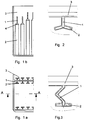
Figur 1- zeigt einen Teil eines Blockkastens mit erfindungsgemäßen Seitenwandrippen mit T-förmigem Querschnitt.
Figur 2- zeigt eine erfindungsgemäße Seitenwandrippe mit dem Querschnitt eines modifizierten T.
Figur 3- zeigt eine erfindungsgemäne Seitenwandrippe mit einer weiteren Modifizierung des T-förmigem Querschnitts.
- Figure 1
- shows a part of a block box with side wall ribs according to the invention with a T-shaped cross section.
- Figure 2
- shows a side wall rib according to the invention with the cross section of a modified T.
- Figure 3
- shows a side wall rib according to the invention with a further modification of the T-shaped cross section.
In einer besonders vorteilhaften Ausführung der Seitenwandrippe ist ihre Querschnittsform exakt T-förmig. Ein mit derartigen Rippen versehenes Kastenteil ist in Figur 1a in einer Draufsicht von oben und in Figur 1b in einer Seitenansicht (mit Blick gegen die Kastentrennwand) wiedergegeben. Der hier lotrecht aus der Kastenwand 3 herausstehende Steg 1 verzweigt sich an seinem dem Inneren des Kastens zugewandten Ende in die Fortsetzungsstege 2, welche gemeinsam den zweiten Schenkel des T bilden und aufgrund ihrer parallelen Ausrichtung zur Kastenwand eine breite Anlagefläche bieten.In a particularly advantageous embodiment of the side wall rib, its cross-sectional shape is exactly T-shaped. A box part provided with such ribs is shown in FIG. 1a in a top view from above and in FIG. 1b in a side view (with a view against the box partition). The
Die Seitenansicht der Figur 1b läßt die erwähnten Abrundungen 4 der Fortsetzungsstege 2 am oberen Ende der Rippen erkennen. Mit einer ähnlichen Abrundung (nicht sichtbar) treten auch die Stege 1 an ihren oberen Enden in die Kastenwand 3 zurück.The side view of FIG. 1b shows the roundings 4 of the
Eine andere vorteilhafte Formgebung für eine Seitenwandrippe gemäß der Erfindung kommt durch eine Abwinkelung der Fortsetzungsstege 2 zustande, so daß sich der aus Figur 2 ersichtliche Querschnitt eines Y ergibt. Die Plattensatzpressung wird in diesem Fall durch die federelastische Abspreizung der leicht gewinkelten Y-Schenkel zur T-Form hin erzielt. Der Winkel zwischen den Schenkeln des Y sollte 150° nicht unterschreiten.Another advantageous shape for a side wall rib according to the invention is achieved by angling the
Gemäß Figur 3 kann einer Seitenwandrippe gemäß der Erfindung eine gewisse Elastizität auch durch eine Winkelung des an die Kastenwand angeformten Steges 1 verliehen werden.According to FIG. 3, a side wall rib according to the invention can also be given a certain elasticity by angling the
Unabhängig von den verschiedenen möglichen Ausgestaltungen der Seitenwandrippen, welche im Rahmen der Erfindung liegen, sollte die Forderung, daß die Anlagefläche mindestens 40% der Plattenfläche beträgt, jedoch stets erfüllt sein. Diese Bedingung läßt sich über die Länge der Fortsetzungsstege, die gegenseitigen Abstände und Höhe der Seitenwandrippen einhalten.Regardless of the various possible configurations of the side wall ribs which are within the scope of the invention, the requirement that the contact surface is at least 40% of the plate surface should always be met. This condition leaves adhere to the length of the extension webs, the mutual distances and the height of the side wall ribs.
Vorteilhaft sind möglichst lange Fortsetzungsstege 2, deren Dicke jedoch mit einer im wesentlichen mit der Dicke der von der Wand ausgehenden Stege 1 übereinstimmt. Die Dicke der Stege 1 wird von den spritztechnischen Möglichkeiten begrenzt und hängt im Einzelfall von der Kastenhöhe ab. Hohe Kästen werden im allgemeinen wegen eines glatten Materialflusses und guter Entformbarkeit dickere Stege erfordern als niedrige Kästen. Dabei ist zu berücksichtigen, daß die Wandstärken der aus elastischen Kunststoffen gefertigten Akkumulatorenkästen selbst nicht mehr als 2 bis 5 mm, insbesondere ca. 2,5 mm, betragen.Advantageously
Möglichst dicke Stege bis zu einer Stärke von ca, 5 mm sind dann vorzusehen, wenn sich die Rippen bis zur Höhe des Deckels erstrecken sollen, wobei sie zusätzlich der Abstützung des Deckels und der Aufnahme von Kräften bei Überkopfverspannung der Batterie dienen können. Die Rippen (1, 2) erstrecken sich im Mittelbereich der Wand 3 weiter zum oberen Rand als im seitlichen Bereich (Figur 1b).Bars as thick as possible up to a thickness of approx. 5 mm are to be provided if the ribs are to extend to the height of the cover, and they can additionally serve to support the cover and absorb forces when the battery is clamped overhead. The ribs (1, 2) extend further in the central region of the
Die erfindungsgemäßen Seitenwandrippen machen den Akkumulatorenbehälter hinsichtlich der Elektrodenbeschickung nicht nur robotergerecht, sie erlauben vor allem dem Batteriehersteller, Akkumulatoren unterschiedlichen Energiegehalts aufgrund einer Bestückung mit entsprechend reduzierten oder verstärkten Plattenblöcken in Blockkästen mit gleichen Außenabmessungen anzubieten, weil allein die Rippen die Einbauweite bestimmen und sowohl dickeren wie dünneren Plattenblöcken problemlos angepaßt werden können. Sie fungieren als Abstandshalter und halten dabei die Elektrodenplatten auf besonders schonende Weise fest, so daß diese selbst unter Rüttelbeanspruchung keinen Schaden nehmen. Dank einer teils materialbedingten, teils strukturbedingten Restelastizität sind die Rippen ferner in der Lage, neben ihrem Festhaltevermögen auch Dickentoleranzen, die sich zwischen Plattensätzen aus dem gleichen Fertigungslos einstellen können, aufzufangen.The side wall ribs according to the invention not only make the storage battery container robot-compatible with regard to the electrode charging, they also allow the battery manufacturer, above all, to offer storage batteries of different energy content due to the fact that they are equipped with correspondingly reduced or reinforced plate blocks in block boxes with the same external dimensions, because the ribs alone determine the installation width and both thicker and thicker thinner plate blocks can be easily adapted. They act as spacers and hold the electrode plates in a particularly gentle manner, so that they are not damaged even when subjected to vibrations. Thanks to a partly elastic and partly structure-related residual elasticity, the ribs are also able to absorb thickness tolerances that can occur between plate sets from the same production batch in addition to their retention.
Claims (8)
Applications Claiming Priority (2)
| Application Number | Priority Date | Filing Date | Title |
|---|---|---|---|
| DE4426770A DE4426770A1 (en) | 1994-07-28 | 1994-07-28 | Accumulator with side wall ribs |
| DE4426770 | 1994-07-28 |
Publications (2)
| Publication Number | Publication Date |
|---|---|
| EP0694979A1 true EP0694979A1 (en) | 1996-01-31 |
| EP0694979B1 EP0694979B1 (en) | 1998-07-08 |
Family
ID=6524377
Family Applications (1)
| Application Number | Title | Priority Date | Filing Date |
|---|---|---|---|
| EP95106529A Expired - Lifetime EP0694979B1 (en) | 1994-07-28 | 1995-04-29 | Storage battery with ribs on the side walls |
Country Status (6)
| Country | Link |
|---|---|
| US (1) | US5624770A (en) |
| EP (1) | EP0694979B1 (en) |
| AT (1) | ATE168223T1 (en) |
| DE (2) | DE4426770A1 (en) |
| DK (1) | DK0694979T3 (en) |
| ES (1) | ES2120101T3 (en) |
Cited By (1)
| Publication number | Priority date | Publication date | Assignee | Title |
|---|---|---|---|---|
| EP2683003A1 (en) * | 2012-07-02 | 2014-01-08 | HOPPECKE Batterien GmbH & Co. KG. | Battery, in particular lead battery |
Families Citing this family (8)
| Publication number | Priority date | Publication date | Assignee | Title |
|---|---|---|---|---|
| US6300005B1 (en) | 1999-03-17 | 2001-10-09 | Gnb Technologies, Inc. | Battery with container compartment and end wall stiffening block |
| US6210829B1 (en) * | 1999-07-30 | 2001-04-03 | Harding Industries, Inc. | Chevron shaped battery jar bridges |
| KR100339804B1 (en) * | 1999-10-12 | 2002-06-07 | 조충환 | A battery jar used in a storage lead battery for an easy injection of gel electrolyte |
| US6376126B1 (en) | 1999-10-13 | 2002-04-23 | Johnson Controls Technology Company | Composite battery container with integral flexible ribs |
| US20040247995A1 (en) * | 2003-06-09 | 2004-12-09 | Devitt John L. | Electrical storage battery |
| DE102009035489A1 (en) * | 2009-07-31 | 2011-02-03 | Daimler Ag | Single cell for a battery |
| JP2011165565A (en) * | 2010-02-12 | 2011-08-25 | Sumitomo Electric Ind Ltd | Molten salt battery |
| FR3011776B1 (en) * | 2013-10-16 | 2017-04-14 | Blue Solutions | ELECTRIC ENERGY STORAGE ASSEMBLY AND METHOD OF ASSEMBLING SUCH ASSEMBLY |
Citations (2)
| Publication number | Priority date | Publication date | Assignee | Title |
|---|---|---|---|---|
| US1526208A (en) * | 1923-01-18 | 1925-02-10 | Gill Storage Battery Company | Storage-battery assembly |
| EP0169179A1 (en) * | 1984-07-19 | 1986-01-22 | ACCUMA S.p.A. | Procedure for making an electric battery housing or casing, and battery housing or casing obtained thereby |
Family Cites Families (5)
| Publication number | Priority date | Publication date | Assignee | Title |
|---|---|---|---|---|
| US3607440A (en) * | 1970-01-29 | 1971-09-21 | Esb Inc | Battery container having springlike packing ribs to accommodate elements of varying thicknesses |
| US4309818A (en) * | 1980-05-27 | 1982-01-12 | General Motors Corporation | Method for manufacturing a preformed flex-rib battery case |
| CA1161217A (en) * | 1980-07-28 | 1984-01-31 | William J. Perkins | Battery container mold |
| US5264304A (en) * | 1991-09-23 | 1993-11-23 | W. R. Grace & Co.-Conn. | Battery separators with T-shaped ribs |
| US5384212A (en) * | 1994-04-25 | 1995-01-24 | Globe-Union Inc. | Flex-rib plaques for batteries |
-
1994
- 1994-07-28 DE DE4426770A patent/DE4426770A1/en not_active Withdrawn
-
1995
- 1995-04-29 DE DE59502742T patent/DE59502742D1/en not_active Expired - Lifetime
- 1995-04-29 AT AT95106529T patent/ATE168223T1/en not_active IP Right Cessation
- 1995-04-29 DK DK95106529T patent/DK0694979T3/en active
- 1995-04-29 EP EP95106529A patent/EP0694979B1/en not_active Expired - Lifetime
- 1995-04-29 ES ES95106529T patent/ES2120101T3/en not_active Expired - Lifetime
- 1995-07-25 US US08/506,837 patent/US5624770A/en not_active Expired - Lifetime
Patent Citations (2)
| Publication number | Priority date | Publication date | Assignee | Title |
|---|---|---|---|---|
| US1526208A (en) * | 1923-01-18 | 1925-02-10 | Gill Storage Battery Company | Storage-battery assembly |
| EP0169179A1 (en) * | 1984-07-19 | 1986-01-22 | ACCUMA S.p.A. | Procedure for making an electric battery housing or casing, and battery housing or casing obtained thereby |
Cited By (1)
| Publication number | Priority date | Publication date | Assignee | Title |
|---|---|---|---|---|
| EP2683003A1 (en) * | 2012-07-02 | 2014-01-08 | HOPPECKE Batterien GmbH & Co. KG. | Battery, in particular lead battery |
Also Published As
| Publication number | Publication date |
|---|---|
| ATE168223T1 (en) | 1998-07-15 |
| DK0694979T3 (en) | 1999-04-19 |
| US5624770A (en) | 1997-04-29 |
| DE59502742D1 (en) | 1998-08-13 |
| DE4426770A1 (en) | 1996-02-01 |
| ES2120101T3 (en) | 1998-10-16 |
| EP0694979B1 (en) | 1998-07-08 |
Similar Documents
| Publication | Publication Date | Title |
|---|---|---|
| DE69911749T2 (en) | PRISMATIC CELL CONSTRUCTION | |
| DE102004043828B4 (en) | battery Pack | |
| EP3467898B1 (en) | Battery having a wall element, and wall element for same | |
| DE2147713A1 (en) | BATTERY HOUSING FOR ONE OR MULTIPLE CELLS | |
| EP0694979B1 (en) | Storage battery with ribs on the side walls | |
| DE202004021589U1 (en) | battery Pack | |
| DE1786308B2 (en) | RESERVE AND DISPENSER CONTAINER FOR BATTERIES | |
| EP2212943B1 (en) | Separator for gel electrolyte storage batteries | |
| DE2834599C3 (en) | Electric battery | |
| DE3117917A1 (en) | BATTERY HOUSING WITH PREFORMED FLEXIBLE RIBS AND METHOD FOR THE PRODUCTION THEREOF | |
| DE102017218107A1 (en) | Energy storage device | |
| DE3409765C2 (en) | ||
| EP0584639B1 (en) | Lead accumulator | |
| EP3061143B1 (en) | Grid arrangement for a plate-shaped battery electrode and storage battery | |
| DE7823496U1 (en) | LEAD ACCUMULATOR | |
| DE3045479C2 (en) | ||
| DE102018123687B4 (en) | Battery box of a block battery | |
| DE2756320A1 (en) | Vibration resistant lead accumulator - with thermoplastic ribbed elements between outer electrodes and container wall | |
| DE19804423C1 (en) | Electrical lead-acid battery | |
| DE2039470C3 (en) | Accumulator, in particular multi-cell lead accumulator, with a block box made of elastic plastic material | |
| DE2516729C3 (en) | accumulator | |
| AT513835B1 (en) | Rechargeable battery | |
| DE2914779A1 (en) | SPACER | |
| DE3728931A1 (en) | Lead-acid accumulator having a plate block clamping holder | |
| DE102018202935A1 (en) | Energy storage cell and method for producing an energy storage cell |
Legal Events
| Date | Code | Title | Description |
|---|---|---|---|
| PUAI | Public reference made under article 153(3) epc to a published international application that has entered the european phase |
Free format text: ORIGINAL CODE: 0009012 |
|
| AK | Designated contracting states |
Kind code of ref document: A1 Designated state(s): AT BE CH DE DK ES FR GB IT LI NL PT SE |
|
| 17P | Request for examination filed |
Effective date: 19960222 |
|
| 17Q | First examination report despatched |
Effective date: 19960725 |
|
| GRAG | Despatch of communication of intention to grant |
Free format text: ORIGINAL CODE: EPIDOS AGRA |
|
| GRAG | Despatch of communication of intention to grant |
Free format text: ORIGINAL CODE: EPIDOS AGRA |
|
| GRAH | Despatch of communication of intention to grant a patent |
Free format text: ORIGINAL CODE: EPIDOS IGRA |
|
| GRAH | Despatch of communication of intention to grant a patent |
Free format text: ORIGINAL CODE: EPIDOS IGRA |
|
| GRAA | (expected) grant |
Free format text: ORIGINAL CODE: 0009210 |
|
| AK | Designated contracting states |
Kind code of ref document: B1 Designated state(s): AT BE CH DE DK ES FR GB IT LI NL PT SE |
|
| REF | Corresponds to: |
Ref document number: 168223 Country of ref document: AT Date of ref document: 19980715 Kind code of ref document: T |
|
| ITF | It: translation for a ep patent filed |
Owner name: BARZANO' E ZANARDO MILANO S.P.A. |
|
| REG | Reference to a national code |
Ref country code: CH Ref legal event code: EP |
|
| GBT | Gb: translation of ep patent filed (gb section 77(6)(a)/1977) |
Effective date: 19980722 |
|
| REF | Corresponds to: |
Ref document number: 59502742 Country of ref document: DE Date of ref document: 19980813 |
|
| REG | Reference to a national code |
Ref country code: CH Ref legal event code: NV Representative=s name: E. BLUM & CO. PATENTANWAELTE |
|
| ET | Fr: translation filed | ||
| REG | Reference to a national code |
Ref country code: ES Ref legal event code: FG2A Ref document number: 2120101 Country of ref document: ES Kind code of ref document: T3 |
|
| REG | Reference to a national code |
Ref country code: PT Ref legal event code: SC4A Free format text: AVAILABILITY OF NATIONAL TRANSLATION Effective date: 19980720 |
|
| REG | Reference to a national code |
Ref country code: DK Ref legal event code: T3 |
|
| PLBE | No opposition filed within time limit |
Free format text: ORIGINAL CODE: 0009261 |
|
| STAA | Information on the status of an ep patent application or granted ep patent |
Free format text: STATUS: NO OPPOSITION FILED WITHIN TIME LIMIT |
|
| 26N | No opposition filed | ||
| REG | Reference to a national code |
Ref country code: GB Ref legal event code: IF02 |
|
| PGFP | Annual fee paid to national office [announced via postgrant information from national office to epo] |
Ref country code: PT Payment date: 20020319 Year of fee payment: 8 |
|
| PGFP | Annual fee paid to national office [announced via postgrant information from national office to epo] |
Ref country code: SE Payment date: 20020325 Year of fee payment: 8 |
|
| PGFP | Annual fee paid to national office [announced via postgrant information from national office to epo] |
Ref country code: CH Payment date: 20020326 Year of fee payment: 8 |
|
| PGFP | Annual fee paid to national office [announced via postgrant information from national office to epo] |
Ref country code: DK Payment date: 20020409 Year of fee payment: 8 |
|
| PGFP | Annual fee paid to national office [announced via postgrant information from national office to epo] |
Ref country code: BE Payment date: 20020416 Year of fee payment: 8 |
|
| PGFP | Annual fee paid to national office [announced via postgrant information from national office to epo] |
Ref country code: AT Payment date: 20020423 Year of fee payment: 8 |
|
| PGFP | Annual fee paid to national office [announced via postgrant information from national office to epo] |
Ref country code: NL Payment date: 20020430 Year of fee payment: 8 |
|
| PG25 | Lapsed in a contracting state [announced via postgrant information from national office to epo] |
Ref country code: AT Free format text: LAPSE BECAUSE OF NON-PAYMENT OF DUE FEES Effective date: 20030429 |
|
| PG25 | Lapsed in a contracting state [announced via postgrant information from national office to epo] |
Ref country code: SE Free format text: LAPSE BECAUSE OF NON-PAYMENT OF DUE FEES Effective date: 20030430 Ref country code: LI Free format text: LAPSE BECAUSE OF NON-PAYMENT OF DUE FEES Effective date: 20030430 Ref country code: DK Free format text: LAPSE BECAUSE OF NON-PAYMENT OF DUE FEES Effective date: 20030430 Ref country code: CH Free format text: LAPSE BECAUSE OF NON-PAYMENT OF DUE FEES Effective date: 20030430 Ref country code: BE Free format text: LAPSE BECAUSE OF NON-PAYMENT OF DUE FEES Effective date: 20030430 |
|
| BERE | Be: lapsed |
Owner name: *VB AUTOBATTERIE G.M.B.H. Effective date: 20030430 |
|
| PG25 | Lapsed in a contracting state [announced via postgrant information from national office to epo] |
Ref country code: PT Free format text: LAPSE BECAUSE OF NON-PAYMENT OF DUE FEES Effective date: 20031031 |
|
| PG25 | Lapsed in a contracting state [announced via postgrant information from national office to epo] |
Ref country code: NL Free format text: LAPSE BECAUSE OF NON-PAYMENT OF DUE FEES Effective date: 20031101 |
|
| NLV4 | Nl: lapsed or anulled due to non-payment of the annual fee |
Effective date: 20031101 |
|
| REG | Reference to a national code |
Ref country code: DK Ref legal event code: EBP |
|
| EUG | Se: european patent has lapsed | ||
| REG | Reference to a national code |
Ref country code: CH Ref legal event code: PL |
|
| REG | Reference to a national code |
Ref country code: PT Ref legal event code: MM4A Free format text: LAPSE DUE TO NON-PAYMENT OF FEES Effective date: 20031031 |
|
| PGFP | Annual fee paid to national office [announced via postgrant information from national office to epo] |
Ref country code: GB Payment date: 20060426 Year of fee payment: 12 |
|
| REG | Reference to a national code |
Ref country code: FR Ref legal event code: CJ Ref country code: FR Ref legal event code: CD |
|
| GBPC | Gb: european patent ceased through non-payment of renewal fee |
Effective date: 20070429 |
|
| PG25 | Lapsed in a contracting state [announced via postgrant information from national office to epo] |
Ref country code: GB Free format text: LAPSE BECAUSE OF NON-PAYMENT OF DUE FEES Effective date: 20070429 |
|
| PGFP | Annual fee paid to national office [announced via postgrant information from national office to epo] |
Ref country code: ES Payment date: 20120510 Year of fee payment: 18 |
|
| PGFP | Annual fee paid to national office [announced via postgrant information from national office to epo] |
Ref country code: FR Payment date: 20130625 Year of fee payment: 19 Ref country code: IT Payment date: 20130420 Year of fee payment: 19 |
|
| REG | Reference to a national code |
Ref country code: DE Ref legal event code: R082 Ref document number: 59502742 Country of ref document: DE Representative=s name: MEISSNER, BOLTE & PARTNER GBR, DE |
|
| PGFP | Annual fee paid to national office [announced via postgrant information from national office to epo] |
Ref country code: DE Payment date: 20140429 Year of fee payment: 20 |
|
| REG | Reference to a national code |
Ref country code: FR Ref legal event code: ST Effective date: 20141231 |
|
| PG25 | Lapsed in a contracting state [announced via postgrant information from national office to epo] |
Ref country code: FR Free format text: LAPSE BECAUSE OF NON-PAYMENT OF DUE FEES Effective date: 20140430 |
|
| PG25 | Lapsed in a contracting state [announced via postgrant information from national office to epo] |
Ref country code: IT Free format text: LAPSE BECAUSE OF NON-PAYMENT OF DUE FEES Effective date: 20140429 |
|
| REG | Reference to a national code |
Ref country code: DE Ref legal event code: R071 Ref document number: 59502742 Country of ref document: DE |
|
| REG | Reference to a national code |
Ref country code: ES Ref legal event code: FD2A Effective date: 20150526 |
|
| PG25 | Lapsed in a contracting state [announced via postgrant information from national office to epo] |
Ref country code: ES Free format text: LAPSE BECAUSE OF NON-PAYMENT OF DUE FEES Effective date: 20140430 |