EP2682829B1 - Dispositif, système et procédé de commande de processus - Google Patents
Dispositif, système et procédé de commande de processus Download PDFInfo
- Publication number
- EP2682829B1 EP2682829B1 EP13173899.9A EP13173899A EP2682829B1 EP 2682829 B1 EP2682829 B1 EP 2682829B1 EP 13173899 A EP13173899 A EP 13173899A EP 2682829 B1 EP2682829 B1 EP 2682829B1
- Authority
- EP
- European Patent Office
- Prior art keywords
- software
- signal
- process control
- output
- controller
- Prior art date
- Legal status (The legal status is an assumption and is not a legal conclusion. Google has not performed a legal analysis and makes no representation as to the accuracy of the status listed.)
- Active
Links
Images


Classifications
-
- G—PHYSICS
- G05—CONTROLLING; REGULATING
- G05B—CONTROL OR REGULATING SYSTEMS IN GENERAL; FUNCTIONAL ELEMENTS OF SUCH SYSTEMS; MONITORING OR TESTING ARRANGEMENTS FOR SUCH SYSTEMS OR ELEMENTS
- G05B15/00—Systems controlled by a computer
- G05B15/02—Systems controlled by a computer electric
-
- G—PHYSICS
- G05—CONTROLLING; REGULATING
- G05B—CONTROL OR REGULATING SYSTEMS IN GENERAL; FUNCTIONAL ELEMENTS OF SUCH SYSTEMS; MONITORING OR TESTING ARRANGEMENTS FOR SUCH SYSTEMS OR ELEMENTS
- G05B19/00—Program-control systems
- G05B19/02—Program-control systems electric
- G05B19/04—Program control other than numerical control, i.e. in sequence controllers or logic controllers
- G05B19/042—Program control other than numerical control, i.e. in sequence controllers or logic controllers using digital processors
-
- G—PHYSICS
- G06—COMPUTING OR CALCULATING; COUNTING
- G06F—ELECTRIC DIGITAL DATA PROCESSING
- G06F9/00—Arrangements for program control, e.g. control units
- G06F9/06—Arrangements for program control, e.g. control units using stored programs, i.e. using an internal store of processing equipment to receive or retain programs
- G06F9/44—Arrangements for executing specific programs
- G06F9/455—Emulation; Interpretation; Software simulation, e.g. virtualisation or emulation of application or operating system execution engines
- G06F9/45533—Hypervisors; Virtual machine monitors
-
- Y—GENERAL TAGGING OF NEW TECHNOLOGICAL DEVELOPMENTS; GENERAL TAGGING OF CROSS-SECTIONAL TECHNOLOGIES SPANNING OVER SEVERAL SECTIONS OF THE IPC; TECHNICAL SUBJECTS COVERED BY FORMER USPC CROSS-REFERENCE ART COLLECTIONS [XRACs] AND DIGESTS
- Y02—TECHNOLOGIES OR APPLICATIONS FOR MITIGATION OR ADAPTATION AGAINST CLIMATE CHANGE
- Y02P—CLIMATE CHANGE MITIGATION TECHNOLOGIES IN THE PRODUCTION OR PROCESSING OF GOODS
- Y02P90/00—Enabling technologies with a potential contribution to greenhouse gas [GHG] emissions mitigation
- Y02P90/02—Total factory control, e.g. smart factories, flexible manufacturing systems [FMS] or integrated manufacturing systems [IMS]
Definitions
- the present invention relates to a process control device, a process control system, and a process control method.
- Patent Document 1 Japanese Patent No. 4399773
- Patent Document 2 International Publication No. 2005/050336
- Patent Document 3 United States Patent Application Publication No. US 2007/0078980
- process control systems of the related art have a configuration such that multiple sensors such as a flowmeter and a thermometer, and an actuator are coupled directly to a controller. The controller controls the actuator in accordance with results of the detection by the sensors, thereby controlling the above various quantities of states.
- plants are often designed to have an approximately 30-year lifetime.
- various devices constituting a process control system such as the above controller, the sensors, and the actuator
- the lifetimes of the devices depend on the lifetimes of the electronic components, and are therefore approximately 10 years.
- a sensor alone can be exchanged when the lifetime thereof expires.
- versatile electronic components are mounted on an I/O card that is an interface of the controller, thereby limiting the lifetime of the controller to approximately 10 years, and also limiting the lifetime of the process control system.
- US 2012 104 295 A1 discloses a device for controlling an actuator includes an input interface that receives a plurality of input signals including a setpoint command signal and a feedback signal. An output interface provides a drive signal to the actuator. First, second, and third redundant loop controllers processes the setpoint command signal and the feedback signal to generate respective actuator control signals. A primary controller compares the actuator control signals to determine whether at least two are substantially similar. The device outputs the drive signal to the actuator according to an actuator control signals that has been determined by the primary controller to be substantially similar to another. Any one of the redundant loop controllers is hot swappable with a replacement loop controller such that loop controller redundancy is operatively maintained by the device in controlling the actuator while one of the redundant loop controllers is hot swapped.
- WO 2012 047 654 A1 discloses a method and apparatus to virtualize a process control system.
- a process control system includes a server cluster including one or more servers. When operating, the server cluster provides a virtual workstation or virtual server, a virtual controller to interoperate with the virtual workstation or server and to implement process control operations, and a virtual input/output device to interoperate with the virtual controller and coupled to one or more field devices within the process control system.
- FIG. 1 is a block diagram illustrating a process control system according to a first embodiment of the present invention.
- a process control system 1 of the first embodiment includes: a field apparatus 10; a controller 20 (process control device); and a monitoring device 30.
- the controller 20 controls the field apparatus 10 while being monitored by the monitoring device 30, thereby controlling an industrial process implemented in a plant (not shown).
- the field apparatus 10 and the controller 20 are connected to a field network N1, and the controller 20 and the monitoring device 30 are connected to a control network N2.
- the field network N1 is a wired network provided in a site of the plant.
- the control network N2 is a wired network connecting the site of the plant and the monitoring room.
- the field network N1 and the control network N2 may be wireless networks.
- the field apparatus 10 includes, for example, a sensor apparatus such as a flowmeter and a thermometer, a valve apparatus such as a flow amount control valve and an on-off valve, an actuator apparatus such as a fan and a motor, and other apparatuses provided in the site of the plant.
- a sensor apparatus 11 first filed apparatus
- a valve apparatus 12 second field apparatus
- the sensor apparatus 11 measures the amount of flow of a fluid.
- the valve apparatus 12 controls the amount of flow of the fluid.
- the field apparatus 10 operates in accordance with control data transmitted from the controller 20 via the field network N1. For example, in a case where a request for transmitting measurement data (data indicating a result of measurement of the amount of flow of the fluid) is transmitted from the controller 20 to the sensor apparatus 11, the sensor apparatus 11 transmits the measurement data to the controller 20 via the field network N1. Additionally, in a case where control data (data that controls the degree of opening of the valve) is transmitted from the controller 20 to the valve, the valve apparatus 12 sets the degree of opening of the valve through which the fluid passes, in accordance with the instruction given by the control data.
- the controller 20 collects measurement data from the field apparatus 10 (such as the sensor apparatus 11) while being monitored by the monitoring device 30, and controls the field apparatus 10 (such as the valve apparatus 12) based on the collected measurement data.
- the function of the controller 20 is implemented by a computer reading software and thus software and hardware resources cooperating.
- the function of the controller 20 is implemented by a hardware 21, which includes an MPU (micro-processing unit), a memory, and the like, executing an installed program.
- a program for implementing a hypervisor 22 virtualizer
- a program for implementing an operating system (OS) 23a first controller
- a program for implementing an operating system 23b second controller
- a program for implementing an application 24a first controller
- a program for implementing an application 24b second controller
- the above hypervisor 22 virtually runs over the hardware 21 in lieu of the hardware.
- the hypervisor 22 is provided for the purpose of replacing the hardware 21 without changing the operating systems 23a and 23b, and the applications 24a and 24b. Additionally, the hypervisor 22 is provided for another purpose of causing the operating system 23a and the application 24a to run independently from the operating system 23b and the application 24b.
- the hypervisor 22 provides to the operating systems 23a and 23b, a similar interface to that before the replacement.
- the operating systems 23a and 23b, which run over the hypervisor 22 are not affected by the replacement of the hardware 21. Therefore, the same operating systems 23a and 23b and the same applications 24a and 24b as used before the replacement can run over the new hardware 21.
- the operating systems 23a and 23b, and the applications 24a and 24b can run as follows.
- the hypervisor 22 includes an input distributor 41 (distributor) and an output acquirer 42 (acquirer).
- the input distributor 41 distributes measurement data and status data (first data) collected from the field apparatus 10 (such as the sensor apparatus 11) to the applications 24a and 24b via the operating systems 23a and 23b, respectively.
- the output acquirer 42 acquires two control data (first and second signals) respectively output from the applications 24a and 24b via the operating systems 23a and 23b. Then, the output acquirer 42 outputs any one of the two acquired control data (here, the control data output from the application 24a) to the field apparatus 10 (such as the valve apparatus 12). Then, the field apparatus 10 (such as the valve apparatus 12) is controlled based on the output control data.
- the output acquirer 42 includes an output comparator 42a that compares the two acquired control data (two control data respectively output from the applications 24a and 24b).
- the reason that the input distributor 41 and the output acquirer 42 are provided in the hypervisor 22 is to make it easy to evaluate controllability at the time of replacing the existing system with a new system.
- the operating systems 23a and 23b independently run over the hypervisor 22.
- the operating systems 23a and 23b perform various managements, such as a process management and a memory management, which are required to cause the applications 24a and 24b to run.
- the applications 24a and 24b independently run over the operating systems 23a and 23b, respectively.
- the applications 24a and 24b perform control of the field apparatus 10, which is required for controlling a process (such as collection of measurement data or the like from the sensor apparatus 11, transmission of control data to the valve apparatus 12, and the like).
- the monitoring device 30 is implemented by, for example, a computer.
- the monitoring device 30 is operated by an operator and used for monitoring a process. Specifically, the monitoring device 30 monitors or manages operating states of the operating systems 23a and 23b, and the applications 24a and 24b, which run in the controller 20. Then, the monitoring device 30 controls the controller 20 in accordance with a result of the monitoring (or in accordance with operational instructions from the operator).
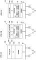
- FIGS. 2A to 2C are diagrams schematically illustrating the procedure of replacing the controller according to the first embodiment of the present invention.
- the monitoring device 30 and the control network N2 shown in FIG. 1 are omitted in FIGS. 2A to 2C .
- the aforementioned operating systems 23a and the application 24a are software (first software) used by an existing controller before the replacement (the controller 100 shown in FIG. 2A ; a second process control device).
- the aforementioned operating systems 23b and the application 24b are software (second software) to be used by a new controller after the replacement (the controller 20 shown in FIGS. 1 , 2B, and 2C ; a first process control device).
- controller 100 When the operation of replacing the controller is initiated, first, an operator at a site specifies a controller to be replaced. It is assumed here that the controller 100 shown in FIG. 2A is specified as the controller to be replaced.
- the controller 100 is a controller in which the operating system 23a and the application 24a run over the hardware 101.
- the controller 20 is a controller in which a program for implementing the hypervisor 22, programs for implementing the operating systems 23a and 23b, and programs for implementing the applications 24a and 24b have been installed.
- the controller 20 When the operator turns on the controller 20 after the above work, the installed programs run, and thus the hypervisor 22, the operating systems 23a and 23b, and the applications 24a and 24b run as shown in FIG. 2B .
- the controller 20 enters a state in which the first software executed by the existing controller 100 (the operating system 23a and the application 24a) is installed in the first controller, and the second software (the operating system 23b and the application 24b) that is newer in version than the first software is installed in the second controller, and the first and second controllers are independently executed.
- FIG. 3 is a flowchart illustrating operation of the controller according to the first embodiment of the present invention. Additionally, FIGS. 4A and 4B illustrate flow of data in the controller according to the first embodiment of the present invention.
- the flowchart shown in FIG. 3 starts when measurement data or status data (first data) collected from the sensor apparatus 11 is input after the operator finishes the replacement work and turns on the controller 20.
- step S11 a process of distributing the measurement data collected from the sensor apparatus 11 to the old and new applications.
- the input distributor 41 distributes the measurement data, which is output from the sensor apparatus 11 and is input to the controller 20 via the field network N1, to the applications 24a and 24b via the operating systems 23a and 23b.
- each of the applications 24a and 24b calculates the amount of control for the valve apparatus 12 (second field apparatus) according to the input measurement data, and outputs control data indicating that amount of control (first and second signals for controlling the field apparatuses). Then, a process of acquiring outputs (first and second signals) of the old and new applications (step S12), a process of outputting the acquired output of the old application to the valve apparatus 12 (step S13), and a process of outputting the acquired output (first signal) of the old application to the valve apparatus 12 (step S13), and a process of comparing the outputs of the old and new applications (step S14) are performed sequentially.
- the acquirer 42 acquires two control data (first and second signals) respectively output from the applications 24a and 24b via the operating systems 23a and 23b. Then, the output acquirer 42 outputs to the valve apparatus 12 via the field network N1, the control data (first signal) output from the application 24a which is one of the two acquired control data. Then, the valve apparatus 12 is controlled based on the control data output from the application 24a. Additionally, the two control data output from the applications 24a and 24b, which are acquired by the output acquirer 42, are input to the output comparator 42a. Then, the output comparator 42a compares control values or output timings of the two control data.
- the output comparator 42a determines whether or not, as a result of the comparison in step S14, the difference in controllability between the old and new applications is within a predetermined reference value (step S 15). If it is determined that the difference in controllability between the old and new applications is within a predetermined reference value (step S15: YES), the hypervisor 22 performs a process of replacing the old application with the new application (step S16).
- a process of terminating execution of the programs for implementing the operating system 23a and the application 24a (a process of terminating the first controller) is performed.
- the controller 20 enters a state in which only the programs for implementing the operating system 23b and the application 24b run over the hypervisor 22 of the controller 20.
- the replacement of the old application with the new application may be performed after the operator of the monitoring device 30 gives allowance of the replacement.
- the control data (second signal) output from the application 24b is output from the output acquirer 42 to the valve apparatus 12 via the field network N1. Then, the valve apparatus 12 is controlled based on the output control data.
- step S17 a process of reporting the result of the comparison performed in step S14 to the monitoring device 30 is performed (step S17).
- the operator of the monitoring device 30 refers to the reported result of the comparison, and determines whether or not to order replacement of the old application with the new application, whether or not to order replacement of the old application with the new application after changing parameters for the new application and thus improving the controllability, and the like.
- a similar process to that in step S16 is performed to replace the old application with the new application.
- the hypervisor 22 runs over the hardware 21 in lieu of the hardware.
- the distributor 41 distributes measurement data or the like output from the sensor apparatus 11, to the applications 24a and 24b that run over the hypervisor 22.
- the output acquire 42 acquires outputs of the applications 24a and 24b, outputs any one of the acquired outputs (the output of the application 24a) to the valve apparatus 12, and compares the acquired outputs.
- FIG. 5 is a block diagram illustrating a configuration of a primary part of a process control system 2 according to a second embodiment of the present invention.
- the process control system 2 of the second embodiment is configured such that comparison of two control data output from the applications 24a and 24b is performed outside the controller 20.
- the process control system 2 has a configuration such that an output acquirer 43 is included in lieu of the output acquirer 42 shown in FIG. 1 , and a output comparison device 50 is newly added.
- the output acquirer 43 acquires two control data output from the applications 24a and 24b via the operating systems 23a and 23b. Then, the output acquirer 43 outputs any one of the two acquired control data (control data output from the application 24a in this case) to the field apparatus 10 (such as the valve apparatus 12).
- the output acquirer 43 differs from the output acquirer 42 shown in FIG. 1 in that the output acquirer 43 does not include the output comparator 42a, and transmits both the two acquired control data to the output comparison device 50.
- the output comparison device 50 is connected to the field network N1, and compares the two control data transmitted from the controller 20 via the field network N1 (two control data respectively output from the applications 24a and 24b).
- the output comparison device 50 need not always be connected to the field network N1.
- the output comparison device 50 is connected to the field network N1 only when the controllability at the time of replacement of the old application with the new application is evaluated. Additionally, the output comparison device 50 can be connected to the control network N1 or the field network N2.
- Operation of the process control system 2 having the above configuration is similar to the operation of the process control system 1 shown in FIG. 1 , except for that comparison of the two control data output from the applications 24a and 24b is performed by the output comparison device 50 provided outside the controller 20.
- a process of distributing the measurement data collected from the sensor apparatus 11 to the old and new applications is performed (step S11).
- each of the applications 24a and 24b outputs control data according to the distributed control data.
- FIG. 6 is a diagram illustrating flow of data in the controller according to the second embodiment of the present invention.
- the output comparison device 50 determines whether or not the difference in controllability between the old and new applications (difference in the control value or the output timing of the control data) is within a predetermined reference value (step S15). If it is determined that the difference in controllability between the old and new applications is within the predetermined reference value (step S15: YES), the hypervisor 22 performs a process of replacing the old application with the new application (step S16).
- step S15 a process of reporting a result of the comparison performed in step S14 to the monitoring device 30 via a gateway (not shown) that connects the networks N1 and N2 (step S17).
- the second embodiment differs from the first embodiment in that the comparison of the outputs of the applications 24a and 24b is performed by the output comparison device 50 provided outside the controller 20.
- the hypervisor 22 runs over the hardware 21, the input distributor 41 distributes the measurement data or the like, the output acquirer 43 acquires the outputs of the applications 24a and 24b, and the like. For this reason, it is possible to easily evaluate the controllability at the time of replacing the application used by the old system (application 24a) with the application to be used by the new system (application 24b). Further, the controllability can be evaluated while the amount of control in an industrial process is controlled by the application used by the old system (application 24a), thereby enabling safer updating of the plant in a shorter time.
- the controller 22 has the configuration that the hypervisor 22 runs, and two applications 24a and 24b run over the hypervisor 22, thereby enabling the existing controller 100 (see FIG. 2A ) to be replaced with the new controller 20 (see FIG. 2C ).
- a configuration is made such that the hypervisor 22 runs, and three or more applications can run over the hypervisor 22, thereby enabling multiple existing controllers to be replaced with one new controller.
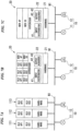
- FIGS. 7A to 7C are diagrams illustrating a first application of the process control systems of the first and second embodiments of the present invention.
- a controller 20 in which the hypervisor 22 runs, and four applications (old AP1 to old AP3, and new AP) can run over the hypervisor 22, is used, thereby replacing three existing controllers 111 to 113 with one new controller 20.
- an application is denoted as "AP" in FIGS. 7A to 7C .
- the output acquirer 42, 43 shown in FIGS. 7A to 7C denote the output acquirer 42 shown in FIG. 1 or the output acquirer 43 shown in FIG. 5 .
- the existing controllers 111 to 113 are controllers in which one operating system and one application run over the hardware.
- the controller 111 has a configuration such that the operating system (old OS1) and the application (old AP1) run.
- the controller 112 has a configuration such that the operating system (old OS2) and the application (old AP2) run.
- the controller 113 has a configuration such that the operating system (old OS3) and the application (old AP3) run.
- the three existing controllers 111 to 113 are removed from the field network N1, and the new controller 20 is connected to the field network N1.
- the new controller 20 is a controller in which a program for implementing the hypervisor 22, programs for implementing the operating systems (old OS1 to old OS3, and new OS), and programs for implementing the applications (old AP1 to old AP3, and new AP) have been installed.
- the controller 20 When the controller 20 is powered on after the above replacement, the installed programs run, and thus the hypervisor 22, the operating systems (old OS1 to old OS3, and new OS), and the applications (old AP1 to old AP3, and new AP) run over the hardware 21, as shown in FIG. 7B .
- the input distributor 41 in the hypervisor 22 distributes to the applications (old AP1 to old AP3, and new AP), measurement data and status data which are collected from the sensor apparatus 11.
- the output acquirer 42 or 43 in the hypervisor 22 acquires outputs of the applications (old AP1 to old AP3, and new AP), and outputs to the valve apparatus 12, the acquired outputs of the applications (old AP1 to old AP3).
- the controller 20 enters a state in which only the programs for implementing the operating system (new OS) and the application (new AP) run over the hypervisor 22 of the controller 20 (see FIG. 7C ).
- FIGS. 8A to 8C are diagrams illustrating a second application of the process control systems of the first and second embodiments of the present invention.
- a controller 20a in which the hypervisor 22 runs, and four applications (old AP1 to old AP3, and new AP11) can run over the hypervisor 22, and a controller 20b (first process control device) in which three applications (old AP4, old AP5, and new AP12) can run over the hypervisor 22, are used, thereby replacing five existing controllers 121 to 125 (controllers 124 and 125 correspond to second and third process control devices) with two new controllers 20a and 20b.
- an application is denoted as "AP" in FIGS. 8A to 8C .
- the output acquirer 42, 43 shown in FIGS. 8A to 8C denote the output acquirer 42 shown in FIG. 1 or the output acquirer 43 shown in FIG. 5 .
- the existing controllers 121 to 125 are controllers in which one operating system and one application run over the hardware.
- the controller 121 has a configuration such that the operating system (old OS1) and the application (old AP1) run.
- the controller 122 has a configuration such that the operating system (old OS2) and the application (old AP2) run.
- the controller 123 has a configuration such that the operating system (old OS3) and the application (old AP3) run.
- the controller 124 has a configuration such that the operating system (old OS4) and the application (old AP4) (first controller) run.
- the controller 125 has a configuration such that the operating system (old OS5) and the application (old AP5) (second controller) run.
- the five existing controllers 121 to 125 (controllers 124 and 125 respectively correspond to second and third process control devices) are removed from the field network N1, and the new controllers 20a and 20b are connected to the field network N1.
- the new controller 20a is a controller in which a program for implementing the hypervisor 22, programs for implementing the operating systems (old OS1 to old OS3, and new OS11), and programs for implementing the applications (old AP1 to old AP3, and new AP11) have been installed.
- the new controller 20b (first process control device) is a controller in which a program for implementing the hypervisor 22, programs for implementing the operating systems (old OS4, old OS5, and new OS 12), and programs for implementing the applications (old AP4, old AP5, and new AP12) have been installed.
- the controller 20b enters a state in which a first software executed by the existing controller 124 (the operating system (old OS4) and the application (old AP4)) is installed in the first controller, a second software executed by the existing controller 125 (the operating system (old OS5) and the application (old AP5)) is installed in the second controller, and a third software that is newer in version than the first and second softwares is installed in the third controller, and the first to third softwares are independently executed.
- a first software executed by the existing controller 124 the operating system (old OS4) and the application (old AP4)
- a second software executed by the existing controller 125 the operating system (old OS5) and the application (old AP5)
- a third software that is newer in version than the first and second softwares is installed in the third controller, and the first to third softwares are independently executed.
- the controllers 20a and 20b When the controllers 20a and 20b are powered on after the above replacement, the installed programs are executed.
- the hypervisor 22, the operating systems (old OS1 to old OS3, and new OS11), and the applications (old AP1 to old AP3, and new AP11) run over the hardware 21, as shown in FIG. 8B .
- the hypervisor 22, the operating systems (old OS4, old OS5, and new OS12), and the applications (old AP4, old AP5, and new AP12) run over the hardware 21.
- the input distributor 41 in the hypervisor 22 that runs in the controller 20a distributes to the applications (old AP1 to old AP3, and new AP11), measurement data and status data which are collected from the sensor apparatus 11.
- the output acquirer 42 or 43 in the hypervisor 22 acquires outputs of the applications (old AP1 to old AP3, and new AP11), and outputs to the valve apparatus 12, the outputs of the applications (old AP1 to old AP3) which are of the acquired outputs.
- the input distributor 41 in the hypervisor 22 that run in the controller 20b distributes to the applications (old AP1, old AP5, and new AP12), measurement data and status data which are collected from the sensor apparatus 11.
- the output acquirer 42 or 43 in the hypervisor 22 acquires outputs of the applications (old AP4, old AP5, and new AP12), and outputs to the valve apparatus 12, the outputs of the applications (old AP4 and old AP5) which are of the acquired outputs.
- the outputs of the applications (old AP 1 to old AP3) and the output of the application (new AP 11) in the controller 20a are compared. Additionally, the outputs (first and second signals) of the applications (old AP4 and old AP5) and the output (third signal) of the application (new AP 12) in the controller 20b are compared. Thus, it is possible to evaluate the controllability at the time of the replacement. More specifically, the difference (first difference) in controllability between the output (first signal) of the old application (old AP4) and the output (third signal) of the new application (new AP12) is within a predetermined reference value.
- the difference (first difference) in controllability is within a predetermined reference value
- a process of replacing the old application (old AP4) with the new application (new AP12) is performed.
- the difference (second difference) in controllability between the output (second signal) of the old application (old AP4) and the output (third signal) of the new application (new AP12) is within the predetermined reference value. If the difference (second difference) in controllability is within the predetermined reference value, a process of replacing the old application (old AP5) with the new application (new AP12) (process of terminating the second controller) is performed.
- the programs for implementing the operating systems (old OS1 to old OS3) and the applications (old AP1 to old AP3) are terminated in the controller 20a.
- the controller 20a enters a state in which only the programs for implementing the operating system (new OS11) and the application (new AP11) run over the hypervisor 22 of the controller 20a.
- the programs for implementing the operating systems (old OS4 and old OS5) and the applications (old AP4 and old AP5) are terminated in the controller 20b.
- the controller 20b enters a state in which only the programs for implementing the operating system (new OS12) and the application (new AP12) run over the hypervisor 22 of the controller 20b (see FIG. 8C ).
- a new controller is connected to the field network N1 to run while the existing redundant controllers (a controlling controller and an idle controller) are connected to the field controllers. Then, the idle controller is removed from the field network N1. Then, another new controller is connected to the field network N1 to run, and the controlling controller transfers control to one of the new controllers. Then, the controlling controller is removed from the field network N1.
- the redundant controllers are provided, it is possible to perform replacement without terminating the plant control system.
- an IO node is connected to the field network N1.
- the IO node converts between signals input to or output from the field apparatus (analog signals), and the signals transferred by communication via the field network N1 (digital signals).
- the IO node and the field apparatus are connected by an analog transmission path (such as a transmission line used for transmitting signals of "4 mA to 20 mA").
- first and second embodiments may be combined to make a configuration such that the controller including the output comparator 42a shown in FIG. 1 and the output comparison device 50 shown in FIG. 5 are connected to the field network N1.
- the controller including the output comparator 42a shown in FIG. 1 and the output comparison device 50 shown in FIG. 5 are connected to the field network N1.
- which of the output comparator 42a and the output comparison device 50 is to perform comparison can be selected, thereby achieving flexible application according to the configuration of the system.
Landscapes
- Engineering & Computer Science (AREA)
- Software Systems (AREA)
- Physics & Mathematics (AREA)
- General Physics & Mathematics (AREA)
- Theoretical Computer Science (AREA)
- Automation & Control Theory (AREA)
- General Engineering & Computer Science (AREA)
- Programmable Controllers (AREA)
- Testing And Monitoring For Control Systems (AREA)
- Safety Devices In Control Systems (AREA)
Claims (4)
- Dispositif de commande de processus (20, 20a, 20b) configuré pour commander un processus industriel mis en oeuvre dans une usine comprenant une pluralité d'appareils de champ (10, 11, 12), qui sont configurés pour réaliser au moins une parmi une mesure et une opération exigées pour commander le processus industriel, le dispositif de commande de processus (20, 20a, 20b) comprenant :une mémoire stockant un logiciel de virtualisation (22), un premier logiciel (23a, 24a), et un deuxième logiciel (23b, 24b), le premier logiciel (23a, 24a) ayant un premier système d'exploitation (23a) et un premier logiciel d'application (24a), le deuxième logiciel ayant un deuxième système d'exploitation (23b) et un deuxième logiciel d'application (23a), le premier logiciel (23a, 24a) ayant été utilisé par un dispositif de commande de processus existant (100) avant un remplacement pour commander un premier appareil de champ (12) de ladite pluralité d'appareils de champ (10, 11, 12) connectés au dispositif de commande de processus (20, 20a, 20b), et le deuxième logiciel (23b, 24b) devant être utilisé par le dispositif de commande de processus (20, 20a, 20b) après un remplacement pour commander ledit premier appareil de champ (12) ;un distributeur d'entrée (41) configuré pour distribuer un signal émis à partir d'un deuxième appareil de champ (11) au premier et au deuxième logiciel (23a, 23b, 24a, 24b) ; etun acquéreur de sorties (42) configuré pour acquérir des sorties du premier et du deuxième logiciel (23a, 23b, 24a, 24b), et émettre l'une quelconque des sorties vers au moins un de la pluralité d'appareils de champ (10, 11, 12) ;le dispositif de commande de processus (20, 20a, 20b) étant configuré pour exécuter, lors de la réception d'un premier signal de données de mesure à partir du deuxième appareil de champ (11), le logiciel de virtualisation (22), pour réaliser au moins :l'acquisition du premier signal émis à partir dudit deuxième appareil de champ (11) ;la distribution du premier signal au premier logiciel (23a, 24a) ;la distribution du premier signal au deuxième logiciel (23b, 24b) ;l'exécution du premier logiciel (23a, 24a) pour que le premier logiciel traite le premier signal pour générer un deuxième signal ; etl'exécution du deuxième logiciel (23b, 24b) pour que le deuxième logiciel traite le premier signal pour générer un troisième signal, dans lequell'acquéreur de sorties (42) comprenant un comparateur de sorties (42a) configuré pour comparer les sorties du premier et du deuxième logiciel (23a, 23b, 24a, 24b) en comparant le deuxième signal et le troisième signal pour déterminer une différence de commandabilité du premier appareil de champ (12) entre le premier logiciel (23a, 24a) et le deuxième logiciel (23b, 24b) ;le dispositif de commande de processus (20, 20a, 20b) étant en outre configuré pour déterminer si oui ou non le premier logiciel (23a, 24a) est remplaçable par le deuxième logiciel (23b, 24b) sur la base de la différence de commandabilité ; etpour remplacer le premier logiciel (23a, 24a) par le deuxième logiciel (23b, 24b) dans un cas où le premier logiciel (23a, 24a) est remplaçable.
- Système de commande de processus comprenant un dispositif de commande de processus (20, 20a, 20b) et un dispositif de comparaison de sorties (50), le dispositif de commande de processus (20, 20a, 20b) étant configuré pour commander un processus industriel mis en oeuvre dans une usine comprenant une pluralité d'appareils de champ (10, 11, 12), qui sont configurés pour réaliser au moins une parmi une mesure et une opération exigées pour commander le processus industriel, le dispositif de commande de processus (20, 20a, 20b) comprenant :une mémoire stockant un logiciel de virtualisation (22), un premier logiciel (24a, 23a), et un deuxième logiciel (24b, 23b), le premier logiciel (23a, 24a) ayant un premier système d'exploitation (23a), et un premier logiciel d'application (24a), le deuxième logiciel ayant un deuxième système d'exploitation (23b) et un deuxième logiciel d'application (23a), le premier logiciel (23a, 24a) ayant été utilisé par un dispositif de commande de processus existant (100) avant un remplacement pour commander un premier appareil de champ (12) de ladite pluralité d'appareils de champ (10, 11, 12) connectés au dispositif de commande de processus (20, 20a, 20b), et le deuxième logiciel (23b, 24b) devant être utilisé par le dispositif de commande de processus (20, 20a, 20b) après un remplacement pour commander ledit premier appareil de champ (12) ;un distributeur d'entrée (41) configuré pour distribuer un signal émis à partir d'un deuxième appareil de champ (11) au premier et au deuxième logiciel (23a, 23b, 24a, 24b) ; etun acquéreur de sorties (43) configuré pour acquérir des sorties du premier et du deuxième logiciel (23a, 23b, 24a, 24b), et émettre l'une quelconque des sorties vers au moins un de la pluralité d'appareils de champ (10, 11, 12) ;le dispositif de commande de processus (20, 20a, 20b) étant configuré pour exécuter, lors de la réception d'un premier signal de données de mesure à partir du deuxième appareil de champ (11), le logiciel de virtualisation (22), pour réaliser au moins :l'acquisition du premier signal émis à partir dudit deuxième appareil de champ (11) ;la distribution du premier signal au premier logiciel (23a, 24a) ;la distribution du premier signal au deuxième logiciel (23b, 24b) ;l'exécution du premier logiciel (23a, 24a) pour que le premier logiciel traite le premier signal pour générer un deuxième signal ; etl'exécution du deuxième logiciel (23b, 24b) pour que le deuxième logiciel traite le premier signal pour générer un troisième signal,dans lequel le dispositif de commande de processus (20, 20a, 20b) est configuré pour réaliser :l'envoi du deuxième signal et du troisième signal au dispositif de comparaison de sorties (50) configuré pour comparer le deuxième signal et le troisième signal, pour déterminer une différence de commandabilité du premier appareil de champ entre le premier logiciel (23a, 24a) et le deuxième logiciel (23b, 24b), et pour déterminer si oui ou non le premier logiciel (23a, 23b) est remplaçable par le deuxième logiciel (23a, 23b) sur la base de la différence de commandabilité du premier appareil de champ (12) ;la réception, à partir du dispositif de comparaison de sorties (50), d'un résultat de détermination indiquant si oui ou non le premier logiciel (23a, 24a) est remplaçable par le deuxième logiciel (23b, 24b) ; etle remplacement du premier logiciel (23a, 24a) par le deuxième logiciel (23b, 24b) dans un cas où le premier logiciel (23a, 24a) est remplaçable.
- Procédé de commande de processus comprenant :la fourniture d'un dispositif de commande de processus selon la revendication 1 ;l'acquisition d'un premier signal de données de mesure émis à partir d'un deuxième appareil de champ (11) ;la distribution du premier signal au premier logiciel (23a, 24a) ;la distribution du premier signal au deuxième logiciel (23b, 24b) ;l'exécution du premier logiciel (23a, 24a) pour que le premier logiciel traite le premier signal pour générer un deuxième signal ;l'exécution du deuxième logiciel (23b, 24b) pour que le deuxième logiciel traite le premier signal pour générer un troisième signal etl'émission d'au moins un des deuxième et troisième signaux vers le premier appareil de champ (12), le procédé de commande de processus comprenant en outre :après l'émission de l'au moins un des deuxième et troisième signaux, la commande du premier appareil de champ (12) sur la base de l'au moins un des deuxième et troisième signaux ;la comparaison du deuxième signal et du troisième signal pour déterminer une différence de commandabilité du premier appareil de champ (12) entre le premier logiciel (23a, 24a) et le deuxième logiciel (23b, 24b) ;le fait de déterminer si oui ou non le premier logiciel (23a, 24a) est remplaçable par le deuxième logiciel (23b, 24b) sur la base de la différence de commandabilité du premier appareil de champ (12) ; etle remplacement du premier logiciel (23a, 24a) par le deuxième logiciel (23b, 24b) dans un cas où le premier logiciel (23a, 24a) est remplaçable.
- Procédé de commande de processus pour un système de commande de processus (20, 20a, 20b, 50) selon la revendication 2 comprenant :la fourniture d'un système de commande de processus selon la revendication 2 ;l'acquisition d'un premier signal de données de mesure émis à partir d'un deuxième appareil de champ (11) ;la distribution du premier signal au premier logiciel (23a, 24a) ;la distribution du premier signal au deuxième logiciel (23b, 24b) ;l'exécution du premier logiciel (23a, 24a) pour que le premier logiciel traite le premier signal pour générer un deuxième signal ;l'exécution du deuxième logiciel (23b, 24b) pour que le deuxième logiciel traite le premier signal pour générer un troisième signal ; etl'émission d'au moins un des deuxième et troisième signaux vers le premier appareil de champ (12),l'envoi du deuxième signal et du troisième signal au dispositif de comparaison de sorties (50) configuré pour comparer le deuxième signal et le troisième signal, pour déterminer une différence de commandabilité du premier appareil de champ (12) entre le premier logiciel (23a, 24a) et le deuxième logiciel (23b, 24b), et pour déterminer si oui ou non le premier logiciel (23a, 24a) est remplaçable par le deuxième logiciel (23b, 24b) sur la base de la différence de commandabilité du premier appareil de champ (12) ;la réception, à partir du dispositif de comparaison de sorties (50), d'un résultat de détermination indiquant si oui ou non le premier logiciel (23a, 24a) est remplaçable par le deuxième logiciel (23b, 24b) ; etle remplacement du premier logiciel (23a, 24a) par le deuxième logiciel (23b, 24b) dans un cas où le premier logiciel (23a, 24a) est remplaçable.
Applications Claiming Priority (1)
| Application Number | Priority Date | Filing Date | Title |
|---|---|---|---|
| JP2012149352A JP5660082B2 (ja) | 2012-07-03 | 2012-07-03 | プロセス制御装置及びシステム |
Publications (3)
| Publication Number | Publication Date |
|---|---|
| EP2682829A2 EP2682829A2 (fr) | 2014-01-08 |
| EP2682829A3 EP2682829A3 (fr) | 2016-12-07 |
| EP2682829B1 true EP2682829B1 (fr) | 2023-08-23 |
Family
ID=48740888
Family Applications (1)
| Application Number | Title | Priority Date | Filing Date |
|---|---|---|---|
| EP13173899.9A Active EP2682829B1 (fr) | 2012-07-03 | 2013-06-26 | Dispositif, système et procédé de commande de processus |
Country Status (4)
| Country | Link |
|---|---|
| US (1) | US9891601B2 (fr) |
| EP (1) | EP2682829B1 (fr) |
| JP (1) | JP5660082B2 (fr) |
| CN (1) | CN103529768B (fr) |
Families Citing this family (9)
| Publication number | Priority date | Publication date | Assignee | Title |
|---|---|---|---|---|
| JP5652444B2 (ja) * | 2012-08-31 | 2015-01-14 | 横河電機株式会社 | 保守支援システム及び方法 |
| JP5713056B2 (ja) * | 2013-06-24 | 2015-05-07 | 横河電機株式会社 | プロセス制御装置及びシステム並びにその更新方法 |
| JP5954338B2 (ja) | 2014-01-14 | 2016-07-20 | 横河電機株式会社 | 計装システム及びその保守方法 |
| JP2015138525A (ja) * | 2014-01-24 | 2015-07-30 | 株式会社東芝 | 仮想プラント監視制御装置 |
| US9720404B2 (en) * | 2014-05-05 | 2017-08-01 | Honeywell International Inc. | Gateway offering logical model mapped to independent underlying networks |
| WO2015169352A1 (fr) * | 2014-05-07 | 2015-11-12 | Abb Technology Ltd | Utilisation de contrôleurs flexibles dans un système de commande de processus |
| JP6265158B2 (ja) * | 2015-03-27 | 2018-01-24 | 横河電機株式会社 | 電子機器 |
| EP3273315B1 (fr) * | 2016-07-19 | 2023-10-18 | ABB Schweiz AG | Plateforme destinee a reutiliser un logiciel existant pour la commande d'appareils de terrain industriels |
| JP7608885B2 (ja) * | 2021-03-11 | 2025-01-07 | オムロン株式会社 | 制御システムおよび制御方法 |
Family Cites Families (17)
| Publication number | Priority date | Publication date | Assignee | Title |
|---|---|---|---|---|
| US5761518A (en) * | 1996-02-29 | 1998-06-02 | The Foxboro Company | System for replacing control processor by operating processor in partially disabled mode for tracking control outputs and in write enabled mode for transferring control loops |
| JP2001202101A (ja) * | 2000-01-18 | 2001-07-27 | Toshiba Corp | 二重化制御システムおよびそのプログラムメンテナンス方法 |
| US8280533B2 (en) * | 2000-06-20 | 2012-10-02 | Fisher-Rosemount Systems, Inc. | Continuously scheduled model parameter based adaptive controller |
| US6901583B1 (en) * | 2001-07-19 | 2005-05-31 | Hewlett-Packard Development Company, L.P. | Method for testing of a software emulator while executing the software emulator on a target machine architecture |
| JP2003316433A (ja) * | 2002-04-22 | 2003-11-07 | Sumitomo Metal Ind Ltd | 制御設備における制御用計算機更新時の試運転確認システム |
| JP4399773B2 (ja) | 2003-11-19 | 2010-01-20 | 横河電機株式会社 | 制御システム |
| JP2005267297A (ja) * | 2004-03-19 | 2005-09-29 | Yaskawa Electric Corp | Plc更新方法 |
| US8327353B2 (en) * | 2005-08-30 | 2012-12-04 | Microsoft Corporation | Hierarchical virtualization with a multi-level virtualization mechanism |
| US20090132057A1 (en) * | 2007-11-20 | 2009-05-21 | Abb Research Ltd. | Control system for controlling the movements of a plurality of mechanical units |
| US8201161B2 (en) * | 2008-01-07 | 2012-06-12 | Lenovo (Singapore) Pte. Ltd. | System and method to update device driver or firmware using a hypervisor environment without system shutdown |
| JP5304331B2 (ja) * | 2009-03-05 | 2013-10-02 | 東芝三菱電機産業システム株式会社 | プラント監視制御システム移行装置 |
| CN101706659A (zh) * | 2009-11-13 | 2010-05-12 | 南京富士通南大软件技术有限公司 | 一种车载设备生产的过程控制系统及其实现方法 |
| DE102010010890B4 (de) * | 2010-03-10 | 2012-03-22 | Siemens Aktiengesellschaft | Verfahren zum Ersetzen einer bestehenden Leiteinrichtung in einem Automatisierungssystem durch eine neue Leiteinrichtung und dazu ausgebildetes Automatisierungssystem |
| US8442663B2 (en) * | 2010-08-23 | 2013-05-14 | Fisher-Rosemount Systems, Inc. | Methods, apparatus and articles of manufacture to test process control systems |
| GB2498659B (en) * | 2010-09-27 | 2015-06-17 | Fisher Rosemount Systems Inc | Methods and apparatus to virtualize a process control system |
| US8820342B2 (en) * | 2010-10-29 | 2014-09-02 | Tapco International Corporation | Actuator control device and method |
| JP5749022B2 (ja) * | 2011-01-11 | 2015-07-15 | 株式会社東芝 | プラント監視システムの更新方法及び更新システム |
-
2012
- 2012-07-03 JP JP2012149352A patent/JP5660082B2/ja active Active
-
2013
- 2013-06-26 EP EP13173899.9A patent/EP2682829B1/fr active Active
- 2013-06-28 US US13/930,697 patent/US9891601B2/en active Active
- 2013-07-01 CN CN201310272410.7A patent/CN103529768B/zh active Active
Also Published As
| Publication number | Publication date |
|---|---|
| CN103529768A (zh) | 2014-01-22 |
| EP2682829A3 (fr) | 2016-12-07 |
| US20140012398A1 (en) | 2014-01-09 |
| JP2014010811A (ja) | 2014-01-20 |
| JP5660082B2 (ja) | 2015-01-28 |
| EP2682829A2 (fr) | 2014-01-08 |
| US9891601B2 (en) | 2018-02-13 |
| CN103529768B (zh) | 2017-04-12 |
Similar Documents
| Publication | Publication Date | Title |
|---|---|---|
| EP2682829B1 (fr) | Dispositif, système et procédé de commande de processus | |
| EP2642360B1 (fr) | Système de commande de processus | |
| US10591886B2 (en) | Control system, control program, and control method for device switching responsive to abnormality detection | |
| US20160313725A1 (en) | A dynamically configurable intelligent controller and control method for machine tools based on dsp/fpga | |
| EP3161562B1 (fr) | Procédé de commande d'une installation de traitement au moyen d'un contrôleur de supervision local redondant | |
| JP5270956B2 (ja) | タービン制御システムを変更するための方法及びシステム | |
| EP3104235B1 (fr) | Dispositif de commande | |
| US11782431B2 (en) | Control device and non-transitory computer-readable recording medium recording program | |
| JP5895906B2 (ja) | プロセス制御装置及びシステム並びにその健全性判定方法 | |
| CN109426233A (zh) | 具有至少一个现场设备和至少一个控制单元的自动化系统 | |
| CN101467113A (zh) | 用于监控过程控制系统中的阀门状态和性能的系统和方法 | |
| US20100185798A1 (en) | Method and communications system for the configuration of a communications module containing a logic component | |
| US12001179B2 (en) | Control subsystem having an integration framework | |
| WO2020100548A1 (fr) | Système de commande et dispositif de commande | |
| JP2016106298A (ja) | プロセス制御装置及びシステム並びにその健全性判定方法 | |
| US9122271B2 (en) | Method for collision-free transfer of a plant from an substantially off mode to an operating mode | |
| JP7314620B2 (ja) | 制御システム、制御装置および制御プログラム | |
| JPWO2018193571A1 (ja) | 機器管理システム、モデル学習方法およびモデル学習プログラム | |
| JP5844013B1 (ja) | 機能ユニット、アナログ入力ユニット、プログラマブルコントローラシステム | |
| CN103154837B (zh) | 用于自动化系统的过程冗余控制的方法 | |
| JP7396526B1 (ja) | プラント制御システム及びプラント制御方法 | |
| CN105320082A (zh) | 一种物联网设备的控制方法 | |
| KR101382461B1 (ko) | 자동차의 제어시스템 | |
| CN102819508A (zh) | 响应来自安防监控子系统信号的方法 | |
| CN120692295A (zh) | 一种工业控制系统 |
Legal Events
| Date | Code | Title | Description |
|---|---|---|---|
| PUAI | Public reference made under article 153(3) epc to a published international application that has entered the european phase |
Free format text: ORIGINAL CODE: 0009012 |
|
| AK | Designated contracting states |
Kind code of ref document: A2 Designated state(s): AL AT BE BG CH CY CZ DE DK EE ES FI FR GB GR HR HU IE IS IT LI LT LU LV MC MK MT NL NO PL PT RO RS SE SI SK SM TR |
|
| AX | Request for extension of the european patent |
Extension state: BA ME |
|
| RIC1 | Information provided on ipc code assigned before grant |
Ipc: G06F 9/455 20060101ALI20160727BHEP Ipc: G05B 19/042 20060101AFI20160727BHEP |
|
| PUAL | Search report despatched |
Free format text: ORIGINAL CODE: 0009013 |
|
| AK | Designated contracting states |
Kind code of ref document: A3 Designated state(s): AL AT BE BG CH CY CZ DE DK EE ES FI FR GB GR HR HU IE IS IT LI LT LU LV MC MK MT NL NO PL PT RO RS SE SI SK SM TR |
|
| AX | Request for extension of the european patent |
Extension state: BA ME |
|
| RIC1 | Information provided on ipc code assigned before grant |
Ipc: G05B 19/042 20060101AFI20161028BHEP Ipc: G06F 9/455 20060101ALI20161028BHEP |
|
| STAA | Information on the status of an ep patent application or granted ep patent |
Free format text: STATUS: REQUEST FOR EXAMINATION WAS MADE |
|
| 17P | Request for examination filed |
Effective date: 20170606 |
|
| RBV | Designated contracting states (corrected) |
Designated state(s): AL AT BE BG CH CY CZ DE DK EE ES FI FR GB GR HR HU IE IS IT LI LT LU LV MC MK MT NL NO PL PT RO RS SE SI SK SM TR |
|
| STAA | Information on the status of an ep patent application or granted ep patent |
Free format text: STATUS: EXAMINATION IS IN PROGRESS |
|
| 17Q | First examination report despatched |
Effective date: 20210114 |
|
| GRAP | Despatch of communication of intention to grant a patent |
Free format text: ORIGINAL CODE: EPIDOSNIGR1 |
|
| STAA | Information on the status of an ep patent application or granted ep patent |
Free format text: STATUS: GRANT OF PATENT IS INTENDED |
|
| INTG | Intention to grant announced |
Effective date: 20230612 |
|
| P01 | Opt-out of the competence of the unified patent court (upc) registered |
Effective date: 20230603 |
|
| GRAS | Grant fee paid |
Free format text: ORIGINAL CODE: EPIDOSNIGR3 |
|
| GRAA | (expected) grant |
Free format text: ORIGINAL CODE: 0009210 |
|
| STAA | Information on the status of an ep patent application or granted ep patent |
Free format text: STATUS: THE PATENT HAS BEEN GRANTED |
|
| REG | Reference to a national code |
Ref country code: DE Ref legal event code: R081 Ref document number: 602013084486 Country of ref document: DE Owner name: YOKOGAWA ELECTRIC CORPORATION, MUSASHINO-SHI, JP Free format text: FORMER OWNER: YOKOGAWA ELECTRIC CORPORATION, TOKYO, JP Ref country code: DE Ref legal event code: R081 Ref document number: 602013084486 Country of ref document: DE Owner name: YOKOGAWA ELECTRIC CORPORATION, MUSASHINO-SHI, JP Free format text: FORMER OWNER: YOKOGAWA ELECTRIC CORPORATION, MUSASHINO-SHI, TOKYO, JP |
|
| AK | Designated contracting states |
Kind code of ref document: B1 Designated state(s): AL AT BE BG CH CY CZ DE DK EE ES FI FR GB GR HR HU IE IS IT LI LT LU LV MC MK MT NL NO PL PT RO RS SE SI SK SM TR |
|
| REG | Reference to a national code |
Ref country code: GB Ref legal event code: FG4D |
|
| REG | Reference to a national code |
Ref country code: CH Ref legal event code: EP |
|
| REG | Reference to a national code |
Ref country code: IE Ref legal event code: FG4D |
|
| REG | Reference to a national code |
Ref country code: DE Ref legal event code: R096 Ref document number: 602013084486 Country of ref document: DE |
|
| REG | Reference to a national code |
Ref country code: LT Ref legal event code: MG9D |
|
| REG | Reference to a national code |
Ref country code: NL Ref legal event code: MP Effective date: 20230823 |
|
| REG | Reference to a national code |
Ref country code: AT Ref legal event code: MK05 Ref document number: 1603311 Country of ref document: AT Kind code of ref document: T Effective date: 20230823 |
|
| PG25 | Lapsed in a contracting state [announced via postgrant information from national office to epo] |
Ref country code: GR Free format text: LAPSE BECAUSE OF FAILURE TO SUBMIT A TRANSLATION OF THE DESCRIPTION OR TO PAY THE FEE WITHIN THE PRESCRIBED TIME-LIMIT Effective date: 20231124 |
|
| PG25 | Lapsed in a contracting state [announced via postgrant information from national office to epo] |
Ref country code: IS Free format text: LAPSE BECAUSE OF FAILURE TO SUBMIT A TRANSLATION OF THE DESCRIPTION OR TO PAY THE FEE WITHIN THE PRESCRIBED TIME-LIMIT Effective date: 20231223 |
|
| PG25 | Lapsed in a contracting state [announced via postgrant information from national office to epo] |
Ref country code: SE Free format text: LAPSE BECAUSE OF FAILURE TO SUBMIT A TRANSLATION OF THE DESCRIPTION OR TO PAY THE FEE WITHIN THE PRESCRIBED TIME-LIMIT Effective date: 20230823 Ref country code: RS Free format text: LAPSE BECAUSE OF FAILURE TO SUBMIT A TRANSLATION OF THE DESCRIPTION OR TO PAY THE FEE WITHIN THE PRESCRIBED TIME-LIMIT Effective date: 20230823 Ref country code: PT Free format text: LAPSE BECAUSE OF FAILURE TO SUBMIT A TRANSLATION OF THE DESCRIPTION OR TO PAY THE FEE WITHIN THE PRESCRIBED TIME-LIMIT Effective date: 20231226 Ref country code: NO Free format text: LAPSE BECAUSE OF FAILURE TO SUBMIT A TRANSLATION OF THE DESCRIPTION OR TO PAY THE FEE WITHIN THE PRESCRIBED TIME-LIMIT Effective date: 20231123 Ref country code: NL Free format text: LAPSE BECAUSE OF FAILURE TO SUBMIT A TRANSLATION OF THE DESCRIPTION OR TO PAY THE FEE WITHIN THE PRESCRIBED TIME-LIMIT Effective date: 20230823 Ref country code: LV Free format text: LAPSE BECAUSE OF FAILURE TO SUBMIT A TRANSLATION OF THE DESCRIPTION OR TO PAY THE FEE WITHIN THE PRESCRIBED TIME-LIMIT Effective date: 20230823 Ref country code: LT Free format text: LAPSE BECAUSE OF FAILURE TO SUBMIT A TRANSLATION OF THE DESCRIPTION OR TO PAY THE FEE WITHIN THE PRESCRIBED TIME-LIMIT Effective date: 20230823 Ref country code: IS Free format text: LAPSE BECAUSE OF FAILURE TO SUBMIT A TRANSLATION OF THE DESCRIPTION OR TO PAY THE FEE WITHIN THE PRESCRIBED TIME-LIMIT Effective date: 20231223 Ref country code: HR Free format text: LAPSE BECAUSE OF FAILURE TO SUBMIT A TRANSLATION OF THE DESCRIPTION OR TO PAY THE FEE WITHIN THE PRESCRIBED TIME-LIMIT Effective date: 20230823 Ref country code: GR Free format text: LAPSE BECAUSE OF FAILURE TO SUBMIT A TRANSLATION OF THE DESCRIPTION OR TO PAY THE FEE WITHIN THE PRESCRIBED TIME-LIMIT Effective date: 20231124 Ref country code: FI Free format text: LAPSE BECAUSE OF FAILURE TO SUBMIT A TRANSLATION OF THE DESCRIPTION OR TO PAY THE FEE WITHIN THE PRESCRIBED TIME-LIMIT Effective date: 20230823 Ref country code: AT Free format text: LAPSE BECAUSE OF FAILURE TO SUBMIT A TRANSLATION OF THE DESCRIPTION OR TO PAY THE FEE WITHIN THE PRESCRIBED TIME-LIMIT Effective date: 20230823 |
|
| PG25 | Lapsed in a contracting state [announced via postgrant information from national office to epo] |
Ref country code: PL Free format text: LAPSE BECAUSE OF FAILURE TO SUBMIT A TRANSLATION OF THE DESCRIPTION OR TO PAY THE FEE WITHIN THE PRESCRIBED TIME-LIMIT Effective date: 20230823 |
|
| PG25 | Lapsed in a contracting state [announced via postgrant information from national office to epo] |
Ref country code: ES Free format text: LAPSE BECAUSE OF FAILURE TO SUBMIT A TRANSLATION OF THE DESCRIPTION OR TO PAY THE FEE WITHIN THE PRESCRIBED TIME-LIMIT Effective date: 20230823 |
|
| PG25 | Lapsed in a contracting state [announced via postgrant information from national office to epo] |
Ref country code: SM Free format text: LAPSE BECAUSE OF FAILURE TO SUBMIT A TRANSLATION OF THE DESCRIPTION OR TO PAY THE FEE WITHIN THE PRESCRIBED TIME-LIMIT Effective date: 20230823 Ref country code: RO Free format text: LAPSE BECAUSE OF FAILURE TO SUBMIT A TRANSLATION OF THE DESCRIPTION OR TO PAY THE FEE WITHIN THE PRESCRIBED TIME-LIMIT Effective date: 20230823 Ref country code: ES Free format text: LAPSE BECAUSE OF FAILURE TO SUBMIT A TRANSLATION OF THE DESCRIPTION OR TO PAY THE FEE WITHIN THE PRESCRIBED TIME-LIMIT Effective date: 20230823 Ref country code: EE Free format text: LAPSE BECAUSE OF FAILURE TO SUBMIT A TRANSLATION OF THE DESCRIPTION OR TO PAY THE FEE WITHIN THE PRESCRIBED TIME-LIMIT Effective date: 20230823 Ref country code: DK Free format text: LAPSE BECAUSE OF FAILURE TO SUBMIT A TRANSLATION OF THE DESCRIPTION OR TO PAY THE FEE WITHIN THE PRESCRIBED TIME-LIMIT Effective date: 20230823 Ref country code: CZ Free format text: LAPSE BECAUSE OF FAILURE TO SUBMIT A TRANSLATION OF THE DESCRIPTION OR TO PAY THE FEE WITHIN THE PRESCRIBED TIME-LIMIT Effective date: 20230823 Ref country code: SK Free format text: LAPSE BECAUSE OF FAILURE TO SUBMIT A TRANSLATION OF THE DESCRIPTION OR TO PAY THE FEE WITHIN THE PRESCRIBED TIME-LIMIT Effective date: 20230823 |
|
| REG | Reference to a national code |
Ref country code: DE Ref legal event code: R097 Ref document number: 602013084486 Country of ref document: DE |
|
| PG25 | Lapsed in a contracting state [announced via postgrant information from national office to epo] |
Ref country code: IT Free format text: LAPSE BECAUSE OF FAILURE TO SUBMIT A TRANSLATION OF THE DESCRIPTION OR TO PAY THE FEE WITHIN THE PRESCRIBED TIME-LIMIT Effective date: 20230823 |
|
| PLBE | No opposition filed within time limit |
Free format text: ORIGINAL CODE: 0009261 |
|
| STAA | Information on the status of an ep patent application or granted ep patent |
Free format text: STATUS: NO OPPOSITION FILED WITHIN TIME LIMIT |
|
| 26N | No opposition filed |
Effective date: 20240524 |
|
| PG25 | Lapsed in a contracting state [announced via postgrant information from national office to epo] |
Ref country code: SI Free format text: LAPSE BECAUSE OF FAILURE TO SUBMIT A TRANSLATION OF THE DESCRIPTION OR TO PAY THE FEE WITHIN THE PRESCRIBED TIME-LIMIT Effective date: 20230823 |
|
| PG25 | Lapsed in a contracting state [announced via postgrant information from national office to epo] |
Ref country code: BG Free format text: LAPSE BECAUSE OF FAILURE TO SUBMIT A TRANSLATION OF THE DESCRIPTION OR TO PAY THE FEE WITHIN THE PRESCRIBED TIME-LIMIT Effective date: 20230823 |
|
| PG25 | Lapsed in a contracting state [announced via postgrant information from national office to epo] |
Ref country code: BG Free format text: LAPSE BECAUSE OF FAILURE TO SUBMIT A TRANSLATION OF THE DESCRIPTION OR TO PAY THE FEE WITHIN THE PRESCRIBED TIME-LIMIT Effective date: 20230823 |
|
| PG25 | Lapsed in a contracting state [announced via postgrant information from national office to epo] |
Ref country code: MC Free format text: LAPSE BECAUSE OF FAILURE TO SUBMIT A TRANSLATION OF THE DESCRIPTION OR TO PAY THE FEE WITHIN THE PRESCRIBED TIME-LIMIT Effective date: 20230823 |
|
| REG | Reference to a national code |
Ref country code: CH Ref legal event code: PL |
|
| PG25 | Lapsed in a contracting state [announced via postgrant information from national office to epo] |
Ref country code: LU Free format text: LAPSE BECAUSE OF NON-PAYMENT OF DUE FEES Effective date: 20240626 |
|
| GBPC | Gb: european patent ceased through non-payment of renewal fee |
Effective date: 20240626 |
|
| PG25 | Lapsed in a contracting state [announced via postgrant information from national office to epo] |
Ref country code: IE Free format text: LAPSE BECAUSE OF NON-PAYMENT OF DUE FEES Effective date: 20240626 |
|
| PG25 | Lapsed in a contracting state [announced via postgrant information from national office to epo] |
Ref country code: BE Free format text: LAPSE BECAUSE OF NON-PAYMENT OF DUE FEES Effective date: 20240630 Ref country code: CH Free format text: LAPSE BECAUSE OF NON-PAYMENT OF DUE FEES Effective date: 20240630 |
|
| PG25 | Lapsed in a contracting state [announced via postgrant information from national office to epo] |
Ref country code: FR Free format text: LAPSE BECAUSE OF NON-PAYMENT OF DUE FEES Effective date: 20240630 |
|
| PG25 | Lapsed in a contracting state [announced via postgrant information from national office to epo] |
Ref country code: GB Free format text: LAPSE BECAUSE OF NON-PAYMENT OF DUE FEES Effective date: 20240626 |
|
| REG | Reference to a national code |
Ref country code: BE Ref legal event code: MM Effective date: 20240630 |
|
| PGFP | Annual fee paid to national office [announced via postgrant information from national office to epo] |
Ref country code: DE Payment date: 20250520 Year of fee payment: 13 |
|
| PG25 | Lapsed in a contracting state [announced via postgrant information from national office to epo] |
Ref country code: CY Free format text: LAPSE BECAUSE OF FAILURE TO SUBMIT A TRANSLATION OF THE DESCRIPTION OR TO PAY THE FEE WITHIN THE PRESCRIBED TIME-LIMIT; INVALID AB INITIO Effective date: 20130626 |
|
| PG25 | Lapsed in a contracting state [announced via postgrant information from national office to epo] |
Ref country code: HU Free format text: LAPSE BECAUSE OF FAILURE TO SUBMIT A TRANSLATION OF THE DESCRIPTION OR TO PAY THE FEE WITHIN THE PRESCRIBED TIME-LIMIT; INVALID AB INITIO Effective date: 20130626 |