EP2642360B1 - Système de commande de processus - Google Patents
Système de commande de processus Download PDFInfo
- Publication number
- EP2642360B1 EP2642360B1 EP13159189.3A EP13159189A EP2642360B1 EP 2642360 B1 EP2642360 B1 EP 2642360B1 EP 13159189 A EP13159189 A EP 13159189A EP 2642360 B1 EP2642360 B1 EP 2642360B1
- Authority
- EP
- European Patent Office
- Prior art keywords
- controller
- network
- controllers
- hypervisor
- control system
- Prior art date
- Legal status (The legal status is an assumption and is not a legal conclusion. Google has not performed a legal analysis and makes no representation as to the accuracy of the status listed.)
- Active
Links
- 238000004886 process control Methods 0.000 title claims description 52
- 230000001360 synchronised effect Effects 0.000 claims description 16
- 238000012544 monitoring process Methods 0.000 claims description 14
- 238000005259 measurement Methods 0.000 claims description 6
- 238000004519 manufacturing process Methods 0.000 claims description 4
- 238000012546 transfer Methods 0.000 claims description 2
- 101150053844 APP1 gene Proteins 0.000 description 11
- 101100189105 Homo sapiens PABPC4 gene Proteins 0.000 description 11
- 102100039424 Polyadenylate-binding protein 4 Human genes 0.000 description 11
- 238000000034 method Methods 0.000 description 11
- 238000010586 diagram Methods 0.000 description 10
- 101100055496 Arabidopsis thaliana APP2 gene Proteins 0.000 description 9
- 101100016250 Saccharomyces cerevisiae (strain ATCC 204508 / S288c) GYL1 gene Proteins 0.000 description 9
- 230000008859 change Effects 0.000 description 8
- 230000005540 biological transmission Effects 0.000 description 7
- 239000012530 fluid Substances 0.000 description 6
- 102100038359 Xaa-Pro aminopeptidase 3 Human genes 0.000 description 4
- 101710081949 Xaa-Pro aminopeptidase 3 Proteins 0.000 description 4
- 230000006870 function Effects 0.000 description 4
- 238000012545 processing Methods 0.000 description 4
- 238000005516 engineering process Methods 0.000 description 2
- 238000009434 installation Methods 0.000 description 2
- 230000009467 reduction Effects 0.000 description 2
- 238000007792 addition Methods 0.000 description 1
- 230000001419 dependent effect Effects 0.000 description 1
- 238000001514 detection method Methods 0.000 description 1
- 238000011161 development Methods 0.000 description 1
- 230000018109 developmental process Effects 0.000 description 1
- 238000012423 maintenance Methods 0.000 description 1
- 238000012986 modification Methods 0.000 description 1
- 230000004048 modification Effects 0.000 description 1
- 230000008569 process Effects 0.000 description 1
- 238000004801 process automation Methods 0.000 description 1
- 238000004088 simulation Methods 0.000 description 1
- 238000006467 substitution reaction Methods 0.000 description 1
Images


Classifications
-
- G—PHYSICS
- G05—CONTROLLING; REGULATING
- G05B—CONTROL OR REGULATING SYSTEMS IN GENERAL; FUNCTIONAL ELEMENTS OF SUCH SYSTEMS; MONITORING OR TESTING ARRANGEMENTS FOR SUCH SYSTEMS OR ELEMENTS
- G05B15/00—Systems controlled by a computer
- G05B15/02—Systems controlled by a computer electric
-
- G—PHYSICS
- G05—CONTROLLING; REGULATING
- G05B—CONTROL OR REGULATING SYSTEMS IN GENERAL; FUNCTIONAL ELEMENTS OF SUCH SYSTEMS; MONITORING OR TESTING ARRANGEMENTS FOR SUCH SYSTEMS OR ELEMENTS
- G05B19/00—Programme-control systems
- G05B19/02—Programme-control systems electric
- G05B19/04—Programme control other than numerical control, i.e. in sequence controllers or logic controllers
- G05B19/042—Programme control other than numerical control, i.e. in sequence controllers or logic controllers using digital processors
- G05B19/0421—Multiprocessor system
-
- G—PHYSICS
- G06—COMPUTING; CALCULATING OR COUNTING
- G06F—ELECTRIC DIGITAL DATA PROCESSING
- G06F11/00—Error detection; Error correction; Monitoring
- G06F11/07—Responding to the occurrence of a fault, e.g. fault tolerance
- G06F11/14—Error detection or correction of the data by redundancy in operation
- G06F11/1479—Generic software techniques for error detection or fault masking
- G06F11/1482—Generic software techniques for error detection or fault masking by means of middleware or OS functionality
-
- G—PHYSICS
- G06—COMPUTING; CALCULATING OR COUNTING
- G06F—ELECTRIC DIGITAL DATA PROCESSING
- G06F11/00—Error detection; Error correction; Monitoring
- G06F11/07—Responding to the occurrence of a fault, e.g. fault tolerance
- G06F11/16—Error detection or correction of the data by redundancy in hardware
- G06F11/20—Error detection or correction of the data by redundancy in hardware using active fault-masking, e.g. by switching out faulty elements or by switching in spare elements
- G06F11/2002—Error detection or correction of the data by redundancy in hardware using active fault-masking, e.g. by switching out faulty elements or by switching in spare elements where interconnections or communication control functionality are redundant
- G06F11/2007—Error detection or correction of the data by redundancy in hardware using active fault-masking, e.g. by switching out faulty elements or by switching in spare elements where interconnections or communication control functionality are redundant using redundant communication media
-
- G—PHYSICS
- G06—COMPUTING; CALCULATING OR COUNTING
- G06F—ELECTRIC DIGITAL DATA PROCESSING
- G06F11/00—Error detection; Error correction; Monitoring
- G06F11/07—Responding to the occurrence of a fault, e.g. fault tolerance
- G06F11/16—Error detection or correction of the data by redundancy in hardware
- G06F11/20—Error detection or correction of the data by redundancy in hardware using active fault-masking, e.g. by switching out faulty elements or by switching in spare elements
- G06F11/202—Error detection or correction of the data by redundancy in hardware using active fault-masking, e.g. by switching out faulty elements or by switching in spare elements where processing functionality is redundant
- G06F11/2038—Error detection or correction of the data by redundancy in hardware using active fault-masking, e.g. by switching out faulty elements or by switching in spare elements where processing functionality is redundant with a single idle spare processing component
-
- G—PHYSICS
- G06—COMPUTING; CALCULATING OR COUNTING
- G06F—ELECTRIC DIGITAL DATA PROCESSING
- G06F11/00—Error detection; Error correction; Monitoring
- G06F11/07—Responding to the occurrence of a fault, e.g. fault tolerance
- G06F11/16—Error detection or correction of the data by redundancy in hardware
- G06F11/20—Error detection or correction of the data by redundancy in hardware using active fault-masking, e.g. by switching out faulty elements or by switching in spare elements
- G06F11/2097—Error detection or correction of the data by redundancy in hardware using active fault-masking, e.g. by switching out faulty elements or by switching in spare elements maintaining the standby controller/processing unit updated
Definitions
- the present invention relates to a process control system.
- the constitution is one in which a plurality of sensors, such as flow gauges and temperature gauges, and actuators, such as valves, are directly connected to controllers, the controllers controlling the actuators in accordance with the results of detection by the sensors, in order to control the above-noted various state quantities.
- sensors such as flow gauges and temperature gauges
- actuators such as valves
- the cost of replacing the process control system is not only the cost of replacing the various devices making up the process control system, but also the cost of lost revenue from products that could have been produced if the plant had not been stopped. If such costs are considered, it is desirable to be able to change or add devices, while maintaining compatibility and without replacing the existing process control system.
- WO 2004/042482 A1 discloses a method for offline parameterization of a field appliance by means of an operating program running on an operating unit.
- DE 10245176 A1 discloses a method for simulation of a field device in a process automation technology network.
- DE 102007062395 A1 discloses an automatic parameterizing method for a field device.
- WO 2011/154211 A1 discloses a method for integrating at least one field device into an automation network.
- FIG. 1 is a block diagram illustrating the constitution of the main parts of a process control system in accordance with the first preferred embodiment of the present invention.
- a process control system 1 of the first preferred embodiment has field devices 10, controllers 20, and a monitoring apparatus 30 and, by the controllers 20 controlling the field devices 10 under monitoring by monitoring apparatus 30, the industrial processes implemented in the plant (not shown) are controlled.
- the field devices 10 are, for example, sensor devices such as flow gauges and temperature sensors, valve devices such as flow amount control valves and open/close valves, actuator devices such as fans, and motors, and other devices installed on-site in a plant.
- sensor devices such as flow gauges and temperature sensors
- valve devices such as flow amount control valves and open/close valves
- actuator devices such as fans, and motors
- FIG. 1 as an aid to understanding, of the field devices 10 installed in the plant, a sensor device 11 that measures the flow amount of a fluid and a valve device 12 that controls the flow amount of a fluid are illustrated.
- the field devices 10 are connected to a network N laid throughout the plant and operate in accordance with control data transmitted from the controllers 20 via the network N. For example, if a controller 20 has transmitted to the sensor device 11 a request to transmit measurement data (data indicating the results of measuring the flow amount of a fluid), the sensor device 11 would transmit the measurement data to the controller 20 via the network N. If a control data (data controlling the opening) has been transmitted from a controller 20 to the valve device 12, the valve device 12 would open the valve passing a fluid to an opening instructed by the control data.
- the above-noted network N is, for example, a cable backbone network laid throughout the plant.
- a controller 20 collects measurement data from a field device 10 such as the sensor device 11 and controls a field device 10 such as the valve device 12 based on the collected measurement data.
- the functionality of the controllers 20 is implemented by reading software into a computer, with software operating in concert with hardware resources.
- the functionality of the controllers 20 is implemented by executing an installed program implementing a hypervisor 22 (virtual part), a program implementing an operating system (OS) 23, and a program implementing an application 24 that are installed in hardware 21 made up of an MPU (microprocessing unit) and memory or the like.
- the hypervisor 22 may be referred to as a virtual part.
- a combination of the operating system (OS) 23 and the application 24 may be referred to as a control unit.
- the hypervisor 22 runs virtually in the hardware 21 in place of hardware, and is provided to enable replacement of the hardware 21 without changing the operating system 23 and the application 24.
- the hypervisor 22 is also provided to achieve mutually synchronous operation between the redundant controllers 20. That is, even if the hardware 21 is changed to hardware having different MPU architecture, memory size, cache size, memory map, device interface, and the like, the hypervisor 22 provides to the operating system 23 the same type of interface that was previously used. As a result, because the operating system 23 running in the hypervisor 22 is not affected by the change of the hardware 21, the operating system 23 and the applications 24 that had previously been used can run on the new hardware 21.
- the operating system 23 runs in the hypervisor 22 and, for example, performs various management, such as process management and memory management that are required for operation of the applications 24.
- the applications 24 run in the operating system 23 and control field devices 10 (for example, collection of measurement data from the field devices 10 and transmission of control data to the field devices 10) necessary for process control.
- the monitoring apparatus 30 monitors and manages the operating status (operating, standby, stopping, copying, idling, and the like) of the operating system 23 and the applications 24 running in the controllers 20. For example, the application in a controller in the standby status can be stopped, transfer being made to another controller that is idling and, after reaching synchronization with a currently used controller, redundant operation being started.
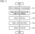
- FIG. 2 is a flowchart illustrating an example of the procedure for replacement of a controller in accordance with the first preferred embodiment of the present invention.
- the on-site workers When the task of replacing a controller 20 is started, the on-site workers first perform the task of specifying the controller 20 to be replaced (step S11). Next, the task of removing the previous controller 20 specified at step S11 from the network N is performed, and the task of connecting a computer (new hardware 21) to be used as the new controller 20 to the network N is performed (step S12).
- the task of installing the software in the computer to implement the functionality of the controller 20 is performed. Specifically, a program implementing the hypervisor 22 is first installed into the new hardware 21 connected to the network N to implement the functionality of the hypervisor 22 (step S13). Next, a program implementing the operating system 23 that had been used previously in the failed controller 20 and a program implementing the application 24 are successively installed, so as to implement the functionality of the operating system 23 and the application 24 (steps S14 and S15). By performing the above-noted tasks, the previously used operating system 23 and application 24 can be run on the new hardware 21.
- the hypervisor 22 that runs in the hardware 21 in place of hardware is provided in the controller 20, and the operating system 23 and the application 24 are caused to run in hypervisor 22.
- the hardware 21 without changing the existing operating system 23 and application 24 that had been previously used, and it is possible to flexibly change and add a controller 20 while maintaining compatibility, without replacing the existing system.
- the backup and restoring thereof are facilitated.
- FIG. 3 is a block diagram illustrating the constitution of the main parts of a process control system in accordance with the second preferred embodiment of the present invention.
- the process control system 2 of the second preferred embodiment imparts redundancy to the constitution of the process control system 1 shown in FIG. 1 for the purpose of increasing the reliability.
- the process control system 2 has the field devices 40 and redundant I/O nodes 50 (input/output nodes and, in place of the network N shown in FIG. 1 , has redundant networks N1 and N2, and further, in place of the controllers 20 shown in FIG. 1 , has the redundant controllers 20a and 20b.
- the redundant I/O nodes may be referred to as input/output nodes.
- the field devices 40 are devices that are installed on-site in a plant, they differ from the field devices 10 in FIG. 1 in that they are connected to the redundant I/O nodes 50 by an analog transmission lines C, and are connected to the networks N1 and N2 via the redundant I/O nodes 50.
- the analog transmission lines C are, for example, transmission lines used for transmitting 4 to 20 mA signals.
- the field devices 40 in the second preferred embodiment input and output analog signals via the analog transmission lines C.
- FIG. 3 similar to FIG. 1 , of the field devices 40 installed in the plant, a sensor device 41 that measures the flow amount of a fluid and a valve device 42 that controls (operates) the flow amount of a fluid are illustrated.
- the redundant I/O nodes 50 are connected to the networks N1 and N2 and converts between the signals (analog signals) input and output at the field devices 40 to signals (digital signals) that are communicated via the networks N1 and N2.
- the networks N1 and N2 are, for example, cable backbone networks laid throughout the plant.
- the controllers 20a and 20b similar to the controllers 20 shown in FIG. 1 , by software working in concert with hardware resources, implement the functionality of the hypervisors 22, the operating systems 23, and the applications 24.
- the controllers 20a and 20b are each connected to the redundant networks N1 and N2.
- the controllers 20a and 20b are operated in mutual synchronization by the hypervisors 22 provided in each thereof.
- the controlling side controls a plurality of field devices, and the standby side performs synchronization with execution information of the controlling side. If trouble occurs on the controlling side, the standby side becomes the controlling side, taking over control and continuing to control the plant.
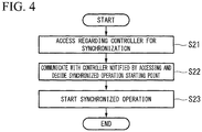
- FIG. 4 is a diagram illustrating an example of the operation occurring when replacing a controller in accordance with the second preferred embodiment of the present invention.
- the hypervisor 22 provided in the new controller 20b accesses the monitoring apparatus 30 regarding the controller to which synchronization is to be done (step S21).
- the redundant controllers 20a and 20b are provided, a notification of the controller 20a as the access result is made from the monitoring apparatus 30 to the controller 20b.
- the hypervisor 22 of the controller 20b communicates with the hypervisor 22 of the notified controller 20a, and decides the starting point for synchronized operation (synchronized operation starting time) (step S22).
- the hypervisor 22 of the controller 20b goes into the state of waiting for the arrival of the synchronized operation starting time decided at step S22.
- the hypervisor 22 of the controller 20a transmits execution information to the hypervisor 22 of the controller 20b and, based on this execution information, the hypervisor 22 of the controller 20b starts synchronized operation (step S23).
- execution information is periodically transmitted from the hypervisor 22 of the controller 20a to the hypervisor 22 of the controller 20b and, based on this execution information, the hypervisor 22 of the controller 20b adjusts the operation timing so as to operate the controller 20a and the controller 20b synchronously.
- the hypervisor 22 of the controller 20b adjusts the operation timing so as to operate the controller 20a and the controller 20b synchronously.
- information indicating the controller to which synchronization is to be done may be stored beforehand in the controller 20b, the hypervisor 22 of the controller 20b deciding the synchronized operation starting point based on that information. By doing this, the accessing of the monitoring apparatus 30 can be omitted.
- hypervisors 22 running in the hardware 21 in place of hardware are provided in each of the redundant controllers 20a and 20b, and the operating system 23 and applications 24 are caused to run in the hypervisors 22, the operation of the controllers 20a and 20b being mutually synchronized by the hypervisors 22.
- replacement of the hardware 21 can be done more flexibly than in the first preferred embodiment. For example, even if replacement of all of the controllers 20a and 20b at one time is not possible for budgetary reasons, it is possible to successively replace the controllers 20a and 20b that are within the budget. Also, replacement is possible not only of the hardware 21, but also of the software (the operating system 23 and the applications 24). An example would be replacement of the applications 24 with software that makes the most of the processing capabilities of the new hardware 21 after replacing all of the hardware 21 of the controllers 20a and 20b.
- FIG. 5 is a diagram describing the procedure for replacing a controller in accordance with the second preferred embodiment of the present invention.
- the operating system 23 and the applications 24 provided in the controllers 20a and 20b are represented as AP/OS.
- the redundant controllers 20a and 20b are assumed to be synchronously operating in the initial state as shown in FIG. 5 (step S30).
- the hardware and the hypervisor can be replaced by new hardware and a new hypervisor without changing the previous AP/OS.
- the controller 20a for which the hardware has been replaced and the controller 20b operate redundantly in synchronous (step S31).
- the hardware and the hypervisor can be replaced by new hardware and a new hypervisor without changing the previous AP/OS.
- the controller 20a for which the hardware has been replaced and the controller 20b for which the hardware has been replaced operate redundantly in synchronous (step S32).
- step S33 if the software of the controller 20a is to be replaced, it is sufficient to change only the previous AP/OS to a new AP/OS. Then, the controller 20b and the controller 20a for which the software has been replaced operate synchronously at a logical synchronization point that was incorporated beforehand (a point having a different execution address, but at which the same logical processing is done) (step S33). In the case also in which software of the controller 20b is to be replaced, similar to the case of replacing the software of the controller 20a, it is sufficient to change only the previous AP/OS to a new AP/OS. By doing this, the controller 20a and the controller 20b operate redundantly in synchronous (step S34). In this manner, the hardware and the AP/OS can be changed while continuing the operation of the AP/OS.
- the backup and restoring thereof are facilitated.
- the redundant I/O nodes 50 are constituted so as to perform analog transmission with the field devices 40, a field bus using digital transmission or wireless may be used.
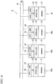
- FIG. 6 is a block diagram illustrating the constitution of the main parts of a process control system in accordance with the third preferred embodiment of the present invention.
- the process control system 3 of the third preferred embodiment in addition to providing redundancy between different controllers within which a plurality of applications 24 that control the field devices 10 are caused to run, a spare controller is additionally provided for the controllers.
- the process control system 3 has controllers 60a to 60c, within which a plurality of applications 24 run, and a spare controller 70, which are connected to the networks N1 and N2.
- the monitoring apparatus 30, the field devices 40, and the redundant I/O nodes 50 and the like shown in FIG. 3 have been omitted in FIG. 6 .
- two applications 24 that run without mutual interference in the operating system 23 are implemented within each of the controllers 60a to 60c.
- the two applications 24 running in the controller 60a will be APP1 and APP2
- the two applications 24 running in the controller 60b will be APP3 and APP1'
- the two applications 24 running in the controller 60c will be APP2' and APP3'.
- the spare controller 70 is provided to implement the same functionality as in a failed controller, in the event that one of the controllers 60a to 60c fails, without performing the task of replacing the failed controller.
- the hypervisor 22 and the operating system 23 are implemented in the controller 70, similar to the controllers 60a to 60c, and provide an interface capable of causing operation of the operating system 23 and applications 24 the same as in the controllers 60a to 60c. For this reason, for example, if the program that implements the application APP1 running in the controller 60a is installed in the spare controller 70, the application APP1 can be caused to run in the spare controller 70.
- controller 60a fails, the state occurs in which the control by the applications APP1 and APP2 that had been running in the controller 60a is handled by the application APP1' running in the controller 60b and the application APP2' running in the controller 60c.
- the spare controller 70 can be caused to operate as the controller 60a. As a result, even if the task of replacing the failed controller 60a is not performed, the condition in which there is redundancy between the applications APP1 and APP1' and the condition in which there is redundancy between the applications APP2 and APP2' are reproduced.
- controllers 60a to 60c are provided in which there are redundant hypervisors 22 operating in the hardware 21 in place of hardware, the operating system 23 and the applications 24 running in the hypervisors 22, and operation of the controllers 60a to 60c being mutually synchronized by the hypervisors 22.
- the controllers 60a to 60c it is possible to flexibly add or change the controllers 60a to 60c while maintaining compatibility and without replacing the existing system, and it is possible to replace the hardware 21 (controllers 60a to 60c) without stopping the process control system 3.
- the spare controller 70 is provided for the controllers 60a to 60c, so that a program implementing an application that had been running in a failed controller is installed in the spare controller 70. For this reason, it is possible to implement the same functionality as the failed controller, without performing the task of replacing the failed controller. Additionally, in the third preferred embodiment, because a plurality of applications are caused to run in each of the controllers 60a to 60c, compared with the case of running only one application, it is possible to reduce the number of controllers (number of the hardware 21), thereby enabling a reduction in the installation surface area, maintenance labor, power consumption, and the like.
- the present invention provides a process control system that enables flexible changing and adding of devices while maintaining compatibility and without replacing an existing system.
- a virtual part that operates in hardware in place of hardware is provided in the controller, and a control unit that controls the operation of field devices is operated in the virtual part. For this reason, it is possible to replace hardware without changing an existing control unit that had previously been used, and it is possible to flexibly change or add a controller while maintaining compatibility, without replacing an existing system.
- the controller can be changed without stopping the plant.
- the term "configured” is used to describe a component, unit or part of a device includes hardware and/or software that is constructed and/or programmed to carry out the desired function.
- unit is used to describe a component, unit or part of a hardware and/or software that is constructed and/or programmed to carry out the desired function.
- Typical examples of the hardware may include, but are not limited to, a device and a circuit.
Landscapes
- Engineering & Computer Science (AREA)
- Physics & Mathematics (AREA)
- General Physics & Mathematics (AREA)
- Automation & Control Theory (AREA)
- General Engineering & Computer Science (AREA)
- Safety Devices In Control Systems (AREA)
- Testing And Monitoring For Control Systems (AREA)
- Programmable Controllers (AREA)
- Hardware Redundancy (AREA)
Claims (7)
- Système de commande de processus (1 ; 2 ; 3) réalisant une commande d'un processus industriel implémenté dans une usine, le système de commande de processus (1 ; 2 ; 3) comprenant :un réseau (N ; N1, N2) prévu dans l'usine ;une pluralité de dispositifs de champ (10 ; 40) connectés au réseau (N ; N1, N2), chacun de la pluralité de dispositifs de champ (10 ; 40) étant configuré pour réaliser au moins l'un d'une mesure et d'un actionnement requis pour commander le processus industriel ; etau moins deux dispositifs de commande (20 ; 20a, 20b ; 60a, 60b, 60c) connectés au réseau (N ; N1, N2), les au moins deux dispositifs de commande étant configurés pour communiquer l'un avec l'autre et réaliser des exploitations redondantes qui sont synchronisées l'une à l'autre,chacun des au moins deux dispositifs de commande (20 ; 20a, 20b ; 60a, 60b, 60c) comportant :un matériel informatique (21) comprenant un processeur et une mémoire ;un hyperviseur (22) sur le matériel informatique (21), l'hyperviseur étant configuré pour parvenir à une exploitation mutuellement synchrone entre les au moins deux dispositifs de commande qui sont synchronisés l'un à l'autre, etune unité de commande (23, 24) sur l'hyperviseur (22), l'unité de commande comprenant un système d'exploitation (23) qui s'exécute sur l'hyperviseur et une application (24) qui s'exécute sur le système d'exploitation (23) pour commander des exploitations des dispositifs de champ via le réseau,dans lequel l'hyperviseur est configuré pour permettre de changer le matériel informatique (21) en un matériel différent qui est différent du matériel informatique (21) sans changer le système d'exploitation (23) et l'application (24).
- Système de commande de processus (1 ; 2 ; 3) selon la revendication 1, dans lequel, lorsqu'un premier dispositif de commande (20a) des au moins deux dispositifs de commande (20 ; 20a, 20b ; 60a, 60b, 60c) fonctionne en tant que côté de commande et qu'un second dispositif de commande (20b) des au moins deux dispositifs de commande (20 ; 20a, 20b ; 60a, 60b, 60c) fonctionne en tant que côté de secours, l'hyperviseur (22) du premier dispositif de commande (20a) des au moins deux dispositifs de commande (20 ; 20a, 20b ; 60a, 60b, 60c) est configuré pour transmettre des informations d'exécution à l'hyperviseur (22) du second dispositif de commande (20b) des au moins deux dispositifs de commande (20 ; 20a, 20b ; 60a, 60b, 60c), et l'hyperviseur (22) du second dispositif de commande (20b) des au moins deux dispositifs de commande (20 ; 20a, 20b ; 60a, 60b, 60c) est configuré pour régler une synchronisation d'exploitation d'après les informations d'exécution.
- Système de commande de processus (2 ; 3) selon la revendication 1, comprenant en outre :
des noeuds d'entrée/de sortie (50) se connectant au réseau (N1, N2), les noeuds d'entrée/de sortie (50) étant configurés pour relayer un signal entré/sorti au niveau des dispositifs de champ (40) et un signal communiqué via le réseau (N1, N2). - Système de commande de processus (3) selon la revendication 1, comprenant en outre :
un dispositif de commande de rechange (70) se connectant au réseau (N1, N2), le dispositif de commande de rechange (70) ayant un hyperviseur (22) configuré pour être capable de provoquer l'exploitation d'une unité de commande (23) qui est la même qu'une unité de commande (23, 24) prévue dans un dispositif de commande (60a, 60b, 60c) dans lequel une panne s'est produite. - Système de commande de processus (2 ; 3) selon la revendication 1, dans lequel le réseau (N1, N2) est rendu redondant.
- Système de commande de processus (2 ; 3) selon la revendication 5, dans lequel
le réseau (N) comporte un premier réseau (N1) et un second réseau (N2), et
le système de commande de processus comprenant en outre :
des noeuds d'entrée/de sortie (50) se connectant au premier réseau (N1) et au second réseau (N2), les noeuds d'entrée/de sortie (50) étant configurés pour relayer un signal entré/sorti au niveau des dispositifs de champ (40) et un signal communiqué via le premier réseau (N1) et le second réseau (N2). - Système de commande de processus (1 ; 2 ; 3) selon la revendication 6, dans lequel
l'unité de commande (23, 24) dans chacun des au moins deux dispositifs de commande (20 ; 20a, 20b ; 60a ; 60b ; 60c) a le système d'exploitation (23) qui s'exécute dans l'hyperviseur (22) et l'application (24) qui s'exécute dans le système d'exploitation (23), et
le système de commande de processus (1 ; 2 ; 3) comprenant en outre :
un appareil de surveillance (30) configuré pour surveiller et gérer un statut d'exploitation du système d'exploitation (23) et les applications (24) s'exécutant dans le dispositif de commande (20 ; 20a, 20b ; 60a, 60b, 60c) de sorte que l'application dans un dispositif de commande dans un statut de secours puisse être arrêtée, un transfert étant réalisé vers un autre dispositif de commande qui est inactif et, après avoir obtenu une synchronisation avec un dispositif de commande actuellement utilisé, une exploitation redondante étant démarrée.
Applications Claiming Priority (1)
| Application Number | Priority Date | Filing Date | Title |
|---|---|---|---|
| JP2012068041A JP5561298B2 (ja) | 2012-03-23 | 2012-03-23 | プロセス制御システム |
Publications (2)
| Publication Number | Publication Date |
|---|---|
| EP2642360A1 EP2642360A1 (fr) | 2013-09-25 |
| EP2642360B1 true EP2642360B1 (fr) | 2018-05-23 |
Family
ID=47900799
Family Applications (1)
| Application Number | Title | Priority Date | Filing Date |
|---|---|---|---|
| EP13159189.3A Active EP2642360B1 (fr) | 2012-03-23 | 2013-03-14 | Système de commande de processus |
Country Status (4)
| Country | Link |
|---|---|
| US (1) | US9261868B2 (fr) |
| EP (1) | EP2642360B1 (fr) |
| JP (1) | JP5561298B2 (fr) |
| CN (1) | CN103324156B (fr) |
Families Citing this family (24)
| Publication number | Priority date | Publication date | Assignee | Title |
|---|---|---|---|---|
| JP5713056B2 (ja) * | 2013-06-24 | 2015-05-07 | 横河電機株式会社 | プロセス制御装置及びシステム並びにその更新方法 |
| JP6020476B2 (ja) * | 2014-01-20 | 2016-11-02 | 横河電機株式会社 | プロセス制御装置及びその更新方法 |
| JP6248901B2 (ja) * | 2014-11-13 | 2017-12-20 | 横河電機株式会社 | 入出力装置 |
| CN107003648B (zh) * | 2014-12-17 | 2019-06-11 | 西门子公司 | 自动化设备的功能模块的检验方法和工程规划系统 |
| JP6299640B2 (ja) * | 2015-03-23 | 2018-03-28 | 横河電機株式会社 | 通信装置 |
| JP6265158B2 (ja) * | 2015-03-27 | 2018-01-24 | 横河電機株式会社 | 電子機器 |
| US10409270B2 (en) * | 2015-04-09 | 2019-09-10 | Honeywell International Inc. | Methods for on-process migration from one type of process control device to different type of process control device |
| JP6344350B2 (ja) | 2015-09-18 | 2018-06-20 | 横河電機株式会社 | 制御装置 |
| EP3273315B1 (fr) | 2016-07-19 | 2023-10-18 | ABB Schweiz AG | Plateforme destinee a reutiliser un logiciel existant pour la commande d'appareils de terrain industriels |
| PL3556109T3 (pl) * | 2016-12-15 | 2021-12-20 | Fmc Technologies, Inc. | Inteligentny blok pomiarowy |
| US10401816B2 (en) * | 2017-07-20 | 2019-09-03 | Honeywell International Inc. | Legacy control functions in newgen controllers alongside newgen control functions |
| CN112204482B (zh) * | 2018-05-31 | 2024-07-26 | 西门子股份公司 | 冗余热备控制系统、方法、控制设备及计算机可读存储介质 |
| EP3609131A1 (fr) * | 2018-08-07 | 2020-02-12 | Siemens Aktiengesellschaft | Contraintes opérationnelles pour les fonctions opérationnelles de dispositifs de champ |
| JP7056460B2 (ja) * | 2018-08-10 | 2022-04-19 | 横河電機株式会社 | 制御システム及び制御装置 |
| US11281182B2 (en) * | 2018-09-05 | 2022-03-22 | Siemens Aktiengesellschaft | Redundant hot standby control system and control device, redundant hot standby method and computer-readable storage medium |
| JP6819660B2 (ja) | 2018-09-26 | 2021-01-27 | 横河電機株式会社 | プロセス制御システム、プロセス制御装置、及びプログラム更新方法 |
| GB2623651A (en) | 2019-06-10 | 2024-04-24 | Fisher Rosemount Systems Inc | Automatic load balancing and performance leveling of virtual nodes running real-time control in process control systems |
| US11422543B2 (en) | 2019-06-10 | 2022-08-23 | Fisher-Rosemount Systems, Inc. | Virtualized real-time I/O in process control systems |
| US11231701B2 (en) | 2019-06-10 | 2022-01-25 | Fisher-Rosemount Systems, Inc. | Publish/subscribe protocol for real-time process control |
| GB2589941B (en) | 2019-06-10 | 2024-03-27 | Fisher Rosemount Systems Inc | Ease of node switchovers in process control systems |
| CN110969419A (zh) * | 2019-12-04 | 2020-04-07 | 中国石化销售股份有限公司华南分公司 | 一种站控plc系统的替换方法及装置 |
| JP2021105792A (ja) * | 2019-12-26 | 2021-07-26 | アズビル株式会社 | コントローラ及び施設監視システム |
| JP7287325B2 (ja) | 2020-03-26 | 2023-06-06 | 横河電機株式会社 | 制御システム、制御装置、及び、フィールド機器へのアクセス方法 |
| JP7264098B2 (ja) * | 2020-03-26 | 2023-04-25 | 横河電機株式会社 | 制御システム |
Family Cites Families (17)
| Publication number | Priority date | Publication date | Assignee | Title |
|---|---|---|---|---|
| US6047222A (en) * | 1996-10-04 | 2000-04-04 | Fisher Controls International, Inc. | Process control network with redundant field devices and buses |
| US6088665A (en) * | 1997-11-03 | 2000-07-11 | Fisher Controls International, Inc. | Schematic generator for use in a process control network having distributed control functions |
| US6285966B1 (en) * | 1998-06-25 | 2001-09-04 | Fisher Controls International, Inc. | Function block apparatus for viewing data in a process control system |
| JP4054509B2 (ja) * | 2000-04-19 | 2008-02-27 | 株式会社東芝 | フィールド機器制御システムおよびコンピュータが読取り可能な記憶媒体 |
| DE10245176A1 (de) * | 2002-09-26 | 2004-04-01 | Endress + Hauser Process Solutions Ag | Verfahren zur Simulation eines Feldgerätes in einem Netzwerk der Prozessautomatisierungstechnik |
| DE10251503A1 (de) | 2002-11-04 | 2004-06-09 | Endress + Hauser Flowtec Ag, Reinach | Verfahren zur Offline-Parametrierung eines Feldgerätes der Prozessautomatisierungstechnik |
| JP4399773B2 (ja) | 2003-11-19 | 2010-01-20 | 横河電機株式会社 | 制御システム |
| JP4193140B2 (ja) * | 2005-01-31 | 2008-12-10 | 横河電機株式会社 | 二重化情報処理システム |
| US7340574B2 (en) * | 2005-08-30 | 2008-03-04 | Rockwell Automation Technologies, Inc. | Method and apparatus for synchronizing an industrial controller with a redundant controller |
| US8359112B2 (en) * | 2006-01-13 | 2013-01-22 | Emerson Process Management Power & Water Solutions, Inc. | Method for redundant controller synchronization for bump-less failover during normal and program mismatch conditions |
| US7814495B1 (en) * | 2006-03-31 | 2010-10-12 | V Mware, Inc. | On-line replacement and changing of virtualization software |
| US8364291B2 (en) * | 2007-11-13 | 2013-01-29 | Rockwell Automation Technologies, Inc. | Method and apparatus for providing redundancy in an industrial control system |
| US20090132057A1 (en) * | 2007-11-20 | 2009-05-21 | Abb Research Ltd. | Control system for controlling the movements of a plurality of mechanical units |
| DE102007062395B4 (de) | 2007-12-20 | 2019-08-08 | Endress + Hauser Flowtec Ag | Verfahren zum Parametrieren eines Feldgerätes der Prozessautomatisierungstechnik |
| US8631404B2 (en) * | 2010-02-18 | 2014-01-14 | Red Hat Israel, Ltd. | Mechanism for downloading hypervisor updates via a virtual hardware device using existing virtual machine-host channels |
| GB201004449D0 (en) * | 2010-02-22 | 2010-05-05 | Corbett Sean | Data accelerator |
| DE102010029952B4 (de) | 2010-06-10 | 2019-06-27 | Endress + Hauser Process Solutions Ag | Verfahren zum Integrieren von zumindest einem Feldgerät in ein Netzwerk der Automatisierungstechnik |
-
2012
- 2012-03-23 JP JP2012068041A patent/JP5561298B2/ja active Active
-
2013
- 2013-03-14 US US13/827,634 patent/US9261868B2/en active Active
- 2013-03-14 EP EP13159189.3A patent/EP2642360B1/fr active Active
- 2013-03-21 CN CN201310091576.9A patent/CN103324156B/zh active Active
Non-Patent Citations (1)
| Title |
|---|
| "Virtualization Reduces the Cost of Supporting Open Industrial Control Systems Virtualization Reduces the Cost of Supporting Open Industrial Control Systems ii Table of Contents", 30 June 2009 (2009-06-30), pages 1 - 9, XP055209155, Retrieved from the Internet <URL:https://www.honeywellprocess.com/library/marketing/whitepapers/HPS Virtualization Whitepaper.pdf> [retrieved on 20150824] * |
Also Published As
| Publication number | Publication date |
|---|---|
| US20130253671A1 (en) | 2013-09-26 |
| JP5561298B2 (ja) | 2014-07-30 |
| JP2013200669A (ja) | 2013-10-03 |
| US9261868B2 (en) | 2016-02-16 |
| CN103324156B (zh) | 2016-06-22 |
| CN103324156A (zh) | 2013-09-25 |
| EP2642360A1 (fr) | 2013-09-25 |
Similar Documents
| Publication | Publication Date | Title |
|---|---|---|
| EP2642360B1 (fr) | Système de commande de processus | |
| US10591886B2 (en) | Control system, control program, and control method for device switching responsive to abnormality detection | |
| EP2049987B1 (fr) | Appareil et procédé pour permettre un rétablissement sur une version logicielle antérieure dans un système de commande de processus | |
| JP5713056B2 (ja) | プロセス制御装置及びシステム並びにその更新方法 | |
| JP2020518921A (ja) | オープンアーキテクチャ産業制御システム | |
| EP2897007B1 (fr) | Dispositif de commande de processus et son procédé de mise à jour | |
| US8924498B2 (en) | Method and system for process control network migration | |
| EP3346381B1 (fr) | Dispositif de commande de services en nuage, système de commande de services en nuage, procédé de commande de services en nuage, programme et support d'informations | |
| US8132042B2 (en) | Method and device for exchanging data on the basis of the OPC communications protocol between redundant process automation components | |
| JP6284043B2 (ja) | プロセス制御システム | |
| US10838381B2 (en) | Setting system, setting device, setting method, and setting program | |
| EP2894527B1 (fr) | Système d'instrumentation et procédé pour maintenir ce dernier | |
| CN105988956B (zh) | 冗余pc系统 | |
| JP2010505167A (ja) | 工作機械を操作するための操作装置 | |
| JP2014010811A (ja) | プロセス制御装置及びシステム | |
| CN109188895A (zh) | 一种基于冗余设计的伺服控制系统 | |
| CN107153351B (zh) | 作动器的冗余控制系统以及用于其冗余控制的方法 | |
| US20160090808A1 (en) | Controlling distributed subsea units | |
| JP5725974B2 (ja) | 受配電監視制御システム | |
| CN201788401U (zh) | 设备生产过程控制管理信息系统 | |
| WO2007075097A1 (fr) | Unite de traitement et procede pour la configuration d'un systeme d'automatisation en reseau | |
| KR101845125B1 (ko) | 가상 슬레이브 디바이스를 내장한 이더켓 기반의 모션 제어모듈 및 제어방법 | |
| KR102116174B1 (ko) | 멀티코어 프로세서 기반의 plc 및 hmi 통합 시스템 | |
| CN113917897B (zh) | 用于对电厂进行操作和监视的装置及其实施方法 | |
| JP7349416B2 (ja) | 分散制御システム |
Legal Events
| Date | Code | Title | Description |
|---|---|---|---|
| PUAI | Public reference made under article 153(3) epc to a published international application that has entered the european phase |
Free format text: ORIGINAL CODE: 0009012 |
|
| AK | Designated contracting states |
Kind code of ref document: A1 Designated state(s): AL AT BE BG CH CY CZ DE DK EE ES FI FR GB GR HR HU IE IS IT LI LT LU LV MC MK MT NL NO PL PT RO RS SE SI SK SM TR |
|
| AX | Request for extension of the european patent |
Extension state: BA ME |
|
| 17P | Request for examination filed |
Effective date: 20140124 |
|
| RBV | Designated contracting states (corrected) |
Designated state(s): AL AT BE BG CH CY CZ DE DK EE ES FI FR GB GR HR HU IE IS IT LI LT LU LV MC MK MT NL NO PL PT RO RS SE SI SK SM TR |
|
| 17Q | First examination report despatched |
Effective date: 20140324 |
|
| REG | Reference to a national code |
Ref country code: DE Ref legal event code: R079 Ref document number: 602013037725 Country of ref document: DE Free format text: PREVIOUS MAIN CLASS: G05B0019042000 Ipc: G05B0015020000 |
|
| RIC1 | Information provided on ipc code assigned before grant |
Ipc: G06F 11/20 20060101ALI20150212BHEP Ipc: G06F 9/445 20060101ALI20150212BHEP Ipc: G05B 19/042 20060101ALI20150212BHEP Ipc: G06F 11/14 20060101ALI20150212BHEP Ipc: G05B 15/02 20060101AFI20150212BHEP |
|
| STAA | Information on the status of an ep patent application or granted ep patent |
Free format text: STATUS: EXAMINATION IS IN PROGRESS |
|
| GRAP | Despatch of communication of intention to grant a patent |
Free format text: ORIGINAL CODE: EPIDOSNIGR1 |
|
| STAA | Information on the status of an ep patent application or granted ep patent |
Free format text: STATUS: GRANT OF PATENT IS INTENDED |
|
| INTG | Intention to grant announced |
Effective date: 20180103 |
|
| GRAS | Grant fee paid |
Free format text: ORIGINAL CODE: EPIDOSNIGR3 |
|
| GRAA | (expected) grant |
Free format text: ORIGINAL CODE: 0009210 |
|
| STAA | Information on the status of an ep patent application or granted ep patent |
Free format text: STATUS: THE PATENT HAS BEEN GRANTED |
|
| AK | Designated contracting states |
Kind code of ref document: B1 Designated state(s): AL AT BE BG CH CY CZ DE DK EE ES FI FR GB GR HR HU IE IS IT LI LT LU LV MC MK MT NL NO PL PT RO RS SE SI SK SM TR |
|
| REG | Reference to a national code |
Ref country code: GB Ref legal event code: FG4D |
|
| REG | Reference to a national code |
Ref country code: CH Ref legal event code: EP |
|
| REG | Reference to a national code |
Ref country code: IE Ref legal event code: FG4D |
|
| REG | Reference to a national code |
Ref country code: AT Ref legal event code: REF Ref document number: 1002001 Country of ref document: AT Kind code of ref document: T Effective date: 20180615 |
|
| REG | Reference to a national code |
Ref country code: DE Ref legal event code: R096 Ref document number: 602013037725 Country of ref document: DE |
|
| REG | Reference to a national code |
Ref country code: NL Ref legal event code: MP Effective date: 20180523 |
|
| REG | Reference to a national code |
Ref country code: LT Ref legal event code: MG4D |
|
| PG25 | Lapsed in a contracting state [announced via postgrant information from national office to epo] |
Ref country code: FI Free format text: LAPSE BECAUSE OF FAILURE TO SUBMIT A TRANSLATION OF THE DESCRIPTION OR TO PAY THE FEE WITHIN THE PRESCRIBED TIME-LIMIT Effective date: 20180523 Ref country code: LT Free format text: LAPSE BECAUSE OF FAILURE TO SUBMIT A TRANSLATION OF THE DESCRIPTION OR TO PAY THE FEE WITHIN THE PRESCRIBED TIME-LIMIT Effective date: 20180523 Ref country code: BG Free format text: LAPSE BECAUSE OF FAILURE TO SUBMIT A TRANSLATION OF THE DESCRIPTION OR TO PAY THE FEE WITHIN THE PRESCRIBED TIME-LIMIT Effective date: 20180823 Ref country code: ES Free format text: LAPSE BECAUSE OF FAILURE TO SUBMIT A TRANSLATION OF THE DESCRIPTION OR TO PAY THE FEE WITHIN THE PRESCRIBED TIME-LIMIT Effective date: 20180523 Ref country code: SE Free format text: LAPSE BECAUSE OF FAILURE TO SUBMIT A TRANSLATION OF THE DESCRIPTION OR TO PAY THE FEE WITHIN THE PRESCRIBED TIME-LIMIT Effective date: 20180523 Ref country code: NO Free format text: LAPSE BECAUSE OF FAILURE TO SUBMIT A TRANSLATION OF THE DESCRIPTION OR TO PAY THE FEE WITHIN THE PRESCRIBED TIME-LIMIT Effective date: 20180823 |
|
| PG25 | Lapsed in a contracting state [announced via postgrant information from national office to epo] |
Ref country code: LV Free format text: LAPSE BECAUSE OF FAILURE TO SUBMIT A TRANSLATION OF THE DESCRIPTION OR TO PAY THE FEE WITHIN THE PRESCRIBED TIME-LIMIT Effective date: 20180523 Ref country code: HR Free format text: LAPSE BECAUSE OF FAILURE TO SUBMIT A TRANSLATION OF THE DESCRIPTION OR TO PAY THE FEE WITHIN THE PRESCRIBED TIME-LIMIT Effective date: 20180523 Ref country code: GR Free format text: LAPSE BECAUSE OF FAILURE TO SUBMIT A TRANSLATION OF THE DESCRIPTION OR TO PAY THE FEE WITHIN THE PRESCRIBED TIME-LIMIT Effective date: 20180824 Ref country code: RS Free format text: LAPSE BECAUSE OF FAILURE TO SUBMIT A TRANSLATION OF THE DESCRIPTION OR TO PAY THE FEE WITHIN THE PRESCRIBED TIME-LIMIT Effective date: 20180523 Ref country code: NL Free format text: LAPSE BECAUSE OF FAILURE TO SUBMIT A TRANSLATION OF THE DESCRIPTION OR TO PAY THE FEE WITHIN THE PRESCRIBED TIME-LIMIT Effective date: 20180523 |
|
| REG | Reference to a national code |
Ref country code: AT Ref legal event code: MK05 Ref document number: 1002001 Country of ref document: AT Kind code of ref document: T Effective date: 20180523 |
|
| PG25 | Lapsed in a contracting state [announced via postgrant information from national office to epo] |
Ref country code: AT Free format text: LAPSE BECAUSE OF FAILURE TO SUBMIT A TRANSLATION OF THE DESCRIPTION OR TO PAY THE FEE WITHIN THE PRESCRIBED TIME-LIMIT Effective date: 20180523 Ref country code: PL Free format text: LAPSE BECAUSE OF FAILURE TO SUBMIT A TRANSLATION OF THE DESCRIPTION OR TO PAY THE FEE WITHIN THE PRESCRIBED TIME-LIMIT Effective date: 20180523 Ref country code: SK Free format text: LAPSE BECAUSE OF FAILURE TO SUBMIT A TRANSLATION OF THE DESCRIPTION OR TO PAY THE FEE WITHIN THE PRESCRIBED TIME-LIMIT Effective date: 20180523 Ref country code: RO Free format text: LAPSE BECAUSE OF FAILURE TO SUBMIT A TRANSLATION OF THE DESCRIPTION OR TO PAY THE FEE WITHIN THE PRESCRIBED TIME-LIMIT Effective date: 20180523 Ref country code: CZ Free format text: LAPSE BECAUSE OF FAILURE TO SUBMIT A TRANSLATION OF THE DESCRIPTION OR TO PAY THE FEE WITHIN THE PRESCRIBED TIME-LIMIT Effective date: 20180523 Ref country code: EE Free format text: LAPSE BECAUSE OF FAILURE TO SUBMIT A TRANSLATION OF THE DESCRIPTION OR TO PAY THE FEE WITHIN THE PRESCRIBED TIME-LIMIT Effective date: 20180523 Ref country code: DK Free format text: LAPSE BECAUSE OF FAILURE TO SUBMIT A TRANSLATION OF THE DESCRIPTION OR TO PAY THE FEE WITHIN THE PRESCRIBED TIME-LIMIT Effective date: 20180523 |
|
| REG | Reference to a national code |
Ref country code: DE Ref legal event code: R097 Ref document number: 602013037725 Country of ref document: DE |
|
| PG25 | Lapsed in a contracting state [announced via postgrant information from national office to epo] |
Ref country code: SM Free format text: LAPSE BECAUSE OF FAILURE TO SUBMIT A TRANSLATION OF THE DESCRIPTION OR TO PAY THE FEE WITHIN THE PRESCRIBED TIME-LIMIT Effective date: 20180523 Ref country code: IT Free format text: LAPSE BECAUSE OF FAILURE TO SUBMIT A TRANSLATION OF THE DESCRIPTION OR TO PAY THE FEE WITHIN THE PRESCRIBED TIME-LIMIT Effective date: 20180523 |
|
| PLBE | No opposition filed within time limit |
Free format text: ORIGINAL CODE: 0009261 |
|
| STAA | Information on the status of an ep patent application or granted ep patent |
Free format text: STATUS: NO OPPOSITION FILED WITHIN TIME LIMIT |
|
| 26N | No opposition filed |
Effective date: 20190226 |
|
| PG25 | Lapsed in a contracting state [announced via postgrant information from national office to epo] |
Ref country code: SI Free format text: LAPSE BECAUSE OF FAILURE TO SUBMIT A TRANSLATION OF THE DESCRIPTION OR TO PAY THE FEE WITHIN THE PRESCRIBED TIME-LIMIT Effective date: 20180523 |
|
| PG25 | Lapsed in a contracting state [announced via postgrant information from national office to epo] |
Ref country code: MC Free format text: LAPSE BECAUSE OF FAILURE TO SUBMIT A TRANSLATION OF THE DESCRIPTION OR TO PAY THE FEE WITHIN THE PRESCRIBED TIME-LIMIT Effective date: 20180523 |
|
| REG | Reference to a national code |
Ref country code: CH Ref legal event code: PL |
|
| GBPC | Gb: european patent ceased through non-payment of renewal fee |
Effective date: 20190314 |
|
| PG25 | Lapsed in a contracting state [announced via postgrant information from national office to epo] |
Ref country code: AL Free format text: LAPSE BECAUSE OF FAILURE TO SUBMIT A TRANSLATION OF THE DESCRIPTION OR TO PAY THE FEE WITHIN THE PRESCRIBED TIME-LIMIT Effective date: 20180523 Ref country code: LU Free format text: LAPSE BECAUSE OF NON-PAYMENT OF DUE FEES Effective date: 20190314 |
|
| REG | Reference to a national code |
Ref country code: BE Ref legal event code: MM Effective date: 20190331 |
|
| PG25 | Lapsed in a contracting state [announced via postgrant information from national office to epo] |
Ref country code: IE Free format text: LAPSE BECAUSE OF NON-PAYMENT OF DUE FEES Effective date: 20190314 Ref country code: GB Free format text: LAPSE BECAUSE OF NON-PAYMENT OF DUE FEES Effective date: 20190314 Ref country code: CH Free format text: LAPSE BECAUSE OF NON-PAYMENT OF DUE FEES Effective date: 20190331 Ref country code: LI Free format text: LAPSE BECAUSE OF NON-PAYMENT OF DUE FEES Effective date: 20190331 |
|
| PG25 | Lapsed in a contracting state [announced via postgrant information from national office to epo] |
Ref country code: FR Free format text: LAPSE BECAUSE OF NON-PAYMENT OF DUE FEES Effective date: 20190331 Ref country code: BE Free format text: LAPSE BECAUSE OF NON-PAYMENT OF DUE FEES Effective date: 20190331 |
|
| PG25 | Lapsed in a contracting state [announced via postgrant information from national office to epo] |
Ref country code: TR Free format text: LAPSE BECAUSE OF FAILURE TO SUBMIT A TRANSLATION OF THE DESCRIPTION OR TO PAY THE FEE WITHIN THE PRESCRIBED TIME-LIMIT Effective date: 20180523 |
|
| PG25 | Lapsed in a contracting state [announced via postgrant information from national office to epo] |
Ref country code: MT Free format text: LAPSE BECAUSE OF NON-PAYMENT OF DUE FEES Effective date: 20190314 Ref country code: PT Free format text: LAPSE BECAUSE OF FAILURE TO SUBMIT A TRANSLATION OF THE DESCRIPTION OR TO PAY THE FEE WITHIN THE PRESCRIBED TIME-LIMIT Effective date: 20180924 |
|
| PG25 | Lapsed in a contracting state [announced via postgrant information from national office to epo] |
Ref country code: CY Free format text: LAPSE BECAUSE OF FAILURE TO SUBMIT A TRANSLATION OF THE DESCRIPTION OR TO PAY THE FEE WITHIN THE PRESCRIBED TIME-LIMIT Effective date: 20180523 |
|
| PG25 | Lapsed in a contracting state [announced via postgrant information from national office to epo] |
Ref country code: IS Free format text: LAPSE BECAUSE OF FAILURE TO SUBMIT A TRANSLATION OF THE DESCRIPTION OR TO PAY THE FEE WITHIN THE PRESCRIBED TIME-LIMIT Effective date: 20180923 |
|
| PG25 | Lapsed in a contracting state [announced via postgrant information from national office to epo] |
Ref country code: HU Free format text: LAPSE BECAUSE OF FAILURE TO SUBMIT A TRANSLATION OF THE DESCRIPTION OR TO PAY THE FEE WITHIN THE PRESCRIBED TIME-LIMIT; INVALID AB INITIO Effective date: 20130314 |
|
| PG25 | Lapsed in a contracting state [announced via postgrant information from national office to epo] |
Ref country code: MK Free format text: LAPSE BECAUSE OF FAILURE TO SUBMIT A TRANSLATION OF THE DESCRIPTION OR TO PAY THE FEE WITHIN THE PRESCRIBED TIME-LIMIT Effective date: 20180523 |
|
| P01 | Opt-out of the competence of the unified patent court (upc) registered |
Effective date: 20230603 |
|
| PGFP | Annual fee paid to national office [announced via postgrant information from national office to epo] |
Ref country code: DE Payment date: 20240220 Year of fee payment: 12 |