EP2682711B1 - Vorrichtung und Verfahren zur dreidimensionalen Messung und Robotersystem mit dieser Vorrichtung - Google Patents
Vorrichtung und Verfahren zur dreidimensionalen Messung und Robotersystem mit dieser Vorrichtung Download PDFInfo
- Publication number
- EP2682711B1 EP2682711B1 EP13174627.3A EP13174627A EP2682711B1 EP 2682711 B1 EP2682711 B1 EP 2682711B1 EP 13174627 A EP13174627 A EP 13174627A EP 2682711 B1 EP2682711 B1 EP 2682711B1
- Authority
- EP
- European Patent Office
- Prior art keywords
- camera
- image
- workpiece
- dimensional
- dimensional measurement
- Prior art date
- Legal status (The legal status is an assumption and is not a legal conclusion. Google has not performed a legal analysis and makes no representation as to the accuracy of the status listed.)
- Not-in-force
Links
- 238000005259 measurement Methods 0.000 title claims description 50
- 238000000034 method Methods 0.000 title description 13
- 238000000691 measurement method Methods 0.000 claims description 3
- 238000012545 processing Methods 0.000 description 23
- 230000036544 posture Effects 0.000 description 18
- 238000010586 diagram Methods 0.000 description 12
- 238000001514 detection method Methods 0.000 description 4
- 230000003287 optical effect Effects 0.000 description 4
- 238000004891 communication Methods 0.000 description 3
- 230000000694 effects Effects 0.000 description 3
- 238000004519 manufacturing process Methods 0.000 description 3
- 239000011159 matrix material Substances 0.000 description 3
- 238000013519 translation Methods 0.000 description 3
- 230000008901 benefit Effects 0.000 description 2
- 238000006243 chemical reaction Methods 0.000 description 2
- 238000013461 design Methods 0.000 description 2
- 230000005484 gravity Effects 0.000 description 2
- 230000005236 sound signal Effects 0.000 description 2
- 230000009466 transformation Effects 0.000 description 2
- 230000005540 biological transmission Effects 0.000 description 1
- 239000000284 extract Substances 0.000 description 1
- 238000012546 transfer Methods 0.000 description 1
Images


Classifications
-
- G—PHYSICS
- G06—COMPUTING; CALCULATING OR COUNTING
- G06T—IMAGE DATA PROCESSING OR GENERATION, IN GENERAL
- G06T7/00—Image analysis
- G06T7/50—Depth or shape recovery
- G06T7/55—Depth or shape recovery from multiple images
- G06T7/593—Depth or shape recovery from multiple images from stereo images
-
- G—PHYSICS
- G01—MEASURING; TESTING
- G01B—MEASURING LENGTH, THICKNESS OR SIMILAR LINEAR DIMENSIONS; MEASURING ANGLES; MEASURING AREAS; MEASURING IRREGULARITIES OF SURFACES OR CONTOURS
- G01B11/00—Measuring arrangements characterised by the use of optical techniques
- G01B11/002—Measuring arrangements characterised by the use of optical techniques for measuring two or more coordinates
-
- G—PHYSICS
- G06—COMPUTING; CALCULATING OR COUNTING
- G06T—IMAGE DATA PROCESSING OR GENERATION, IN GENERAL
- G06T2207/00—Indexing scheme for image analysis or image enhancement
- G06T2207/10—Image acquisition modality
- G06T2207/10004—Still image; Photographic image
- G06T2207/10012—Stereo images
-
- G—PHYSICS
- G06—COMPUTING; CALCULATING OR COUNTING
- G06T—IMAGE DATA PROCESSING OR GENERATION, IN GENERAL
- G06T2207/00—Indexing scheme for image analysis or image enhancement
- G06T2207/30—Subject of image; Context of image processing
- G06T2207/30108—Industrial image inspection
- G06T2207/30164—Workpiece; Machine component
-
- Y—GENERAL TAGGING OF NEW TECHNOLOGICAL DEVELOPMENTS; GENERAL TAGGING OF CROSS-SECTIONAL TECHNOLOGIES SPANNING OVER SEVERAL SECTIONS OF THE IPC; TECHNICAL SUBJECTS COVERED BY FORMER USPC CROSS-REFERENCE ART COLLECTIONS [XRACs] AND DIGESTS
- Y10—TECHNICAL SUBJECTS COVERED BY FORMER USPC
- Y10S—TECHNICAL SUBJECTS COVERED BY FORMER USPC CROSS-REFERENCE ART COLLECTIONS [XRACs] AND DIGESTS
- Y10S901/00—Robots
- Y10S901/46—Sensing device
Definitions
- the present invention relates to a three-dimensional measurement apparatus for capturing images of a workpiece from two or more view points to make a three-dimensional measurement or view the workpiece stereoscopically, and a robot system including the same.
- a three-dimensional measurement apparatus which captures images with a plurality of cameras in making a three-dimensional measurement or stereoscopic viewing to acquire three-dimensional information in order to make a three-dimensional measurement from the three-dimensional information.
- a stereo method is widely known, which extracts feature points from captured two images, respectively, and establishes correspondences among the extracted feature points to make a three-dimensional measurement by the principle of triangulation.
- the partial cropping function can reduce the data volume to be handled, and hence has the advantage of being able to perform transfer of image data and image processing at a higher speed than the case of using all pixels.
- the above-mentioned partial cropping function is required to preset the range of reading pixels on the image sensor. Therefore, for example, when objects are conveyed along a production line in such a state that the objects vary in position, there arises a problem of making it difficult to adapt the partial cropping function to the state.
- the present invention provides a three-dimensional measurement apparatus including: a first camera for capturing an image of a workpiece; a second camera for capturing an image of the workpiece from a view point different from the first camera; and a control unit for calculating three-dimensional coordinates from a first image acquired by capturing the workpiece with the first camera and preset virtual workpiece depth information, calculating a projection of a three-dimensional image of the workpiece to the second camera from the calculated three-dimensional coordinates and a posture parameter of the second camera relative to the first camera, setting a cropping range of the second camera based on the calculated projection, and measuring a three-dimensional position of the workpiece from the first image captured with the first camera and a second image cropped in the cropping range of the second camera.
- the present invention also provides a three-dimensional measurement method including: a first image acquiring step for capturing a workpiece with a first camera to acquire a first image; a three-dimensional coordinate calculating step for calculating three-dimensional coordinates from the first image acquired in the first image acquiring step and virtual workpiece depth information; a projection calculating step for calculating a projection of the three-dimensional coordinates to a second camera from a posture parameter of the second camera relative to the first camera and the three-dimensional coordinates; a cropping range setting step for setting a cropping range of a second image to be cropped from the second camera based on the projection calculated in the projection calculating step; a second image acquiring step for acquiring the second image in the cropping range set in the cropping range setting step; and a three-dimensional measurement step for making a three-dimensional measurement of the workpiece from the first image and the second image.
- FIG. 1 is a perspective view illustrating the robot system 1 according to an exemplary embodiment of the present invention.
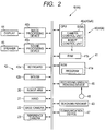
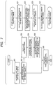
- FIG. 2 is a block diagram illustrating the configuration of a control device 4 in the robot system 1 according to the exemplary embodiment.
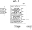
- FIG. 3 is a block diagram illustrating the configuration of a camera control unit 5 according to the exemplary embodiment.
- the robot system 1 includes a robot 2 for assembling a workpiece, a mounting base 3 on which the robot 2 assembles the workpiece, and the control device 4 for controlling the robot 2.
- the robot 2 is a six-shaft multi-joint general-purpose robot including a robot arm 20, a hand 21 attached to the tip of the robot arm, a base camera 22 as a first camera, and a reference camera 23 as a second camera.
- a robot arm 20 a hand 21 attached to the tip of the robot arm
- a base camera 22 as a first camera
- a reference camera 23 as a second camera.
- two cameras i.e. the base camera 22 and the reference camera 23 are used, but a stereo camera unit which can obtain images at two viewpoints may be used.
- the robot arm 20 is equipped with six actuators (not illustrated) for driving each joint to rotate about each joint axis.
- the six actuators are selectively driven, respectively, to move the hand 21 attached to the tip to any three-dimensional position.
- the hand 21 is equipped with a gripping portion 21a for gripping the workpiece and an actuator, not illustrated, for driving the gripping portion 21a.
- the gripping portion 21a is moved by the driving of the robot arm 20 to a position in which the actuator is so driven that the gripping portion 21a will grip the workpiece.
- a force sensor, not illustrated, is provided in the hand 21 to regulate a grip force when the workpiece is gripped.
- the hand 21 is detachably attached to the tip of the robot arm 20 in a manner to be changeable according to the shape of the workpiece to work on.
- the base camera 22 is attached to the tip of the robot arm 20 to capture an image of the workpiece in order to acquire a first image of the workpiece.
- the reference camera 23 is attached adjacent to the base camera 22 at the tip of the robot arm 20 to capture an image of the workpiece from a view point different from the base camera 22 in order to acquire a second image of the workpiece.
- the mounting base 3 is formed into a rectangular box shape, and provided with a planar placement section 30 with the workpiece placed on the top face thereof.
- a jig 31 used to assemble the workpiece is provided substantially in a central portion of the placement section 30.
- a support 32 for immovably supporting the base end section of the robot arm 20, a part feeder 33, and a tool holder 34 are provided at the corners of the placement section 30, respectively.
- Four casters 35 ... for moving the mounting base 3 and four fixing brackets 36 ... for fixing the mounting base 3 to the floor are provided at the bottom of the mounting base 3 so that the mounting base 3 can be fixed after the mounting base 3 is moved to any position.
- the control device 4 is so configured that the robot arm 20, the hand 21, the base camera 22, and the reference camera 23 are connected through a bus to a computer main body having a calculating device 40 and a storing device 41.
- An input device 42, a teaching pendant 43, a display 44, a speaker 45, a recording medium reading device 46, a communication device 47, and the like are also connected to the computer main body through the bus. In FIG. 2 , interfaces for these connections are not illustrated.
- the calculating device 40 includes a CPU 40a, an image processing device 40b, and a sound processing device 40c.
- the CPU 40a includes a camera control unit 5 and a robot control unit 6.
- the camera control unit 5 measures a three-dimensional position of a workpiece according to various programs stored in the storing device 41 and the settings input from the input device 42.
- the camera control unit 5 includes a first image acquiring section 51, a three-dimensional coordinate calculating section 52, a projection calculating section 53, a cropping range setting section 54, a second image acquiring section 55, and a three-dimensional measurement section 56.
- the first image acquiring section 51 captures a workpiece with the base camera 22 to acquire a first image of the workpiece.
- the three-dimensional coordinate calculating section 52 calculates three-dimensional coordinates from the first image acquired in the first image acquiring section 51 and preset virtual workpiece depth information.
- the virtual workpiece depth information may be set, for example, with reference to a focal distance at the time of capturing the workpiece with the base camera 22.
- the projection calculating section 53 calculates the projection of a three-dimensional image of the workpiece onto the image sensor of the reference camera 23 from the camera parameters of the reference camera 23 and the base camera 22, and the three-dimensional coordinates calculated in the three-dimensional coordinate calculating section 52.
- the cropping range setting section 54 sets a cropping range of pixels on the image sensor of the reference camera 23.
- the second image acquiring section 55 captures an image of the workpiece in the cropping range on the image sensor of the reference camera 23 set in the cropping range setting section 54 to acquire a second image.
- the three-dimensional measurement section 56 measures a three-dimensional position of the workpiece from the first image and the second image. The measurement of the three-dimensional position of the workpiece by the camera control unit 5 will be described in detail later.
- the robot control unit 6 controls the robot arm 20 and the hand 21.
- the description of the control of the robot arm 20 and the hand 21 performed by the robot control unit 6 will be omitted.
- the image processing device 40b controls the display 44 in accordance with a drawing instruction from the CPU 40a to cause the display 44 to display a predetermined image on the screen.
- the sound processing device 40c generates a sound signal in accordance with a sound generation instruction from the CPU 40a to output the sound signal to the speaker 45.
- the storing device 41 is connected to the CPU 40a through the bus, and includes a ROM 41a in which the various programs and data are stored, and a RAM 41b reserved as a working area of the CPU 40a.
- the various programs for measuring the workpiece three-dimensionally are stored in the ROM 41a in addition to drive programs for the robot arm 20 and the hand 21.
- a three-dimensional measurement program for executing a first image acquiring step, a three-dimensional coordinate calculating step, a projection calculating step, a cropping range setting step, a second image acquiring step, and a three-dimensional measurement step to be described later is stored.
- virtual workpiece depth information and data such as camera parameters of the base camera 22 and the reference camera 23, from the input device 42, these are also stored in the ROM 41a.
- the input device 42 is composed of a keyboard 42a and a mouse 42b to enable input of information necessary to measure the three-dimensional position of the workpiece and other instructions.
- the recording medium reading device 46 is used to read a computer-readable recording medium 48 that has recorded, for example, the three-dimensional measurement program, and to store the three-dimensional measurement program in the ROM 41a.
- the communication device 47 is used to download the three-dimensional measurement program distributed from the Internet through the communication device 47 without using the recording medium 48 mentioned above.
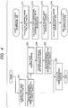
- FIG. 4 is a flowchart of a three-dimensional measurement by the camera control unit 5 according to the first embodiment.
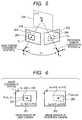
- FIG. 5 is a diagram illustrating the positional relationship between a cropping range in each of images, acquired with the base camera 22 and the reference camera 23, and a projected point according to the first embodiment.
- FIG. 6 is a diagram illustrating image sensors of the base camera 22 and the reference camera 23 according to the first embodiment.
- the internal parameters are parameters required to calculate a projection from the coordinates of any three-dimensional point to a point on an image, which can be determined by a known camera calibration technique. In the embodiment, the following is used as the internal parameters.
- the internal parameters of the base camera 22 can be expressed as (f L , c xL , c yL , s xL , s yL ).
- the internal parameters of the reference camera 23 can be expressed as (f R , c xR , c yR , s xR , s yR ).
- the subscript L indicates the base camera 22 drawn on the left hand of the drawings
- the subscript R indicates the reference camera 23 drawn on the right side of the drawings.
- the posture parameters represent relative postures of the base camera 22 and the reference camera 23, which can be determined by the known camera calibration technique.
- the posture parameters of the base camera 22 and the reference camera 23 are represented by a rotation matrix R and a translation vector t.
- a base camera coordinate system C L and a reference camera coordinate system C R are coordinate systems, which are representative of the postures of the respective cameras and arranged to agree with the coordinate systems of images in X and Y directions with their origins at the lens principal point of each camera.
- the above-mentioned posture parameters represent the relative postures of the base camera coordinate system C L and the reference camera coordinate system C R .
- Reference numerals 201 and 202 illustrated in FIG. 5 and FIG. 6 represent image sensor planes of the base camera 22 and the reference camera 23, respectively, to acquire images as a result of projecting any object (e.g. workpiece) onto the image sensor planes 201 and 202.
- the lens principal point is reversed to the actual physical layout of the image sensors in FIG. 5 for simplifying the description.
- step S01 first image acquiring step
- step S02 image processing is performed on the first image to detect the workpiece in the image
- any of known various image processing techniques such as pattern matching or binarization can be used.
- step S03 a reference camera cropping range 206 to be set in the reference camera 23 is calculated. The following will describe the cropping step S03 by dividing the step into sub-steps S11 to S14.
- a base camera cropping range 203 is calculated based on the result of extracting the target object in the first image (step S11).
- the base camera cropping range 203 for example, the smallest rectangular area surrounding an image area of the target object extracted in the first image is calculated.
- a cropping reference point P L is set for the calculated base camera cropping range 203.
- the cropping reference point P L be substantially the center of the base camera cropping range 203, any point may be used as long as the point is uniquely determined for the base camera cropping range 203.
- P L the center of gravity of the base camera cropping range 203
- the image coordinates are denoted by P L (c L , r L )
- P L is expressed as follows.
- s xL and s yL denote the image sensor size as internal parameters of the base camera 22
- c xL and c yL denote the position of the center of the optical axis on the image coordinates.
- f L denotes the focal distance of the base camera 22.
- a three-dimensional point P W of the workpiece is calculated by using the cropping reference point P L and virtual workpiece depth information (step S12: three-dimensional coordinate calculating step).
- the depth information is information for defining the distance from the lens of the base camera 22 to an area to be measured, which is preset by a user and prestored in the ROM 41a.
- a workpiece distance at which the lens comes into focus may be set as the depth information.
- the distance may be determined from a design value. For example, for production equipment, it is often the case that the layout rules between the workpiece and the camera are predetermined according to the production process to be carried out. Therefore, the virtual workpiece depth information can be easily set.
- a projected point P R of the three-dimensional point P W to the reference camera 23 is calculated (step S13: projection calculating step).
- the three-dimensional point P W described in the base camera coordinate system C L is transformed to a reference camera coordinate system C R .
- P R (x' R , y' R , z' R ) is expressed as follows.
- c R r R x ⁇ R / s xR + c xR y ⁇ R / s yR + c yR
- the image coordinates of the projected point P R as a result of projecting the three-dimensional point P W to the reference camera 23 can be calculated.
- a reference camera cropping range 206 to be set in the reference camera 23 is determined with reference to the image coordinates of the projected point P R (step S14: cropping range setting step). For example, as illustrated in FIG. 6 , a rectangular area with the projected point P R as the center of gravity is set as the reference camera cropping range 206.
- a cropping width w' and a cropping height h' of the reference camera cropping range 206 may be determined with reference to the width w and the height h of the base camera cropping range 203, or set as fixed values in advance.
- the cropping range to be set in the reference camera 23 can be automatically calculated based on the cropping range set in the base camera 22 by executing the above processing steps S11 to S14.
- a second image captured with the reference camera 23 in the cropping range is acquired (step S04: second image acquiring step), and the workpiece is extracted by performing image processing on the second image (step S05).
- a three-dimensional position of the workpiece is measured using the first image and the second image (step S06: three-dimensional measurement step). Since the measurement of the three-dimensional position of the workpiece in the three-dimensional measurement step can be made by typical image processing, the description thereof will be omitted here.
- the robot system 1 automatically calculates the reference camera cropping range to be set in the reference camera 23 based on the base camera cropping range set in the base camera 22 to measure the three-dimensional position based on the respective cropped images.
- the images to be calculated can be reduced, i.e., the amount of information and the amount of transmission can be reduced.
- This enables high-speed image processing for the three-dimensional measurement, and hence reduction in measurement time.
- the takt time (process working time) of the robot system 1 can be reduced.
- a robot system 1A according to a second embodiment of the present invention will be described with reference to FIG. 7 to FIG. 9 while using FIG. 1 to FIG. 3 .
- a method of measuring the three-dimensional position by the camera control unit is different from that in the first embodiment. Therefore, in the second embodiment, an emphasis is placed on a point different from the first embodiment, i.e. on the method of measuring the three-dimensional position by the camera control unit, and the same components as those in the first embodiment are given the same reference numerals to omit the description.
- the robot system 1A includes the robot 2, the mounting base 3, and a control device 4A for controlling the robot 2.
- the control device 4A includes a calculating device 40A and the storing device 41.
- the calculating device 40A includes a CPU 40aA, the image processing device 40b, and the sound processing device 40c.
- the CPU 40aA includes a camera control unit 5A and the robot control unit 6.
- FIG. 7 is a flowchart of a three-dimensional measurement by the camera control unit 5A according to the second embodiment.
- FIG. 8 is a diagram illustrating the positional relationship between a cropping range in each of images, acquired with the base camera 22 and the reference camera 23, and a projected three-dimensional image according to the second embodiment.
- FIG. 9 is a diagram illustrating image sensors of the base camera 22 and the reference camera 23 according to the second embodiment.
- the internal parameters of the base camera 22 are expressed as (f L , c xL , c yL , s xL , s yL ), the internal parameters of the reference camera 23 are expressed as (f R , c xR , c yR , S xR , s yR ), and these are prestored in the ROM 41a.
- the base camera coordinate system C L and the reference camera coordinate system C R are coordinate systems, which are representative of the postures of the base camera 22 and the reference camera 23, respectively, and arranged to agree with the coordinate systems of images in X and Y directions with their origins at the lens principal point of each camera.
- the above-mentioned posture parameters represent the relative postures of the base camera coordinate system C L and the reference camera coordinate system C R .
- Reference numerals 201 and 202 illustrated in FIG. 8 and FIG. 9 represent image sensor planes of the base camera 22 and the reference camera 23, respectively, to acquire images as a result of projecting any object (e.g. workpiece) onto the image sensor planes 201 and 202.
- the lens principal point is reversed to the actual physical layout of the image sensors in FIG. 8 for simplifying the description.
- step S01 first image capturing step
- step S02 image processing is performed on the first image to detect the workpiece in the image
- any of known various image processing techniques such as pattern matching or binarization can be used.
- step S03 a reference camera cropping range 307 to be set in the reference camera 23 is calculated. The following will describe the cropping step S03 by dividing the step into sub-steps S21 to S24.
- a base camera cropping range 303 is calculated based on the result of extracting the target object in the first image (step S21).
- the base camera cropping range 303 for example, the smallest rectangular area surrounding an image area of the target object extracted in the first image is calculated.
- step S22 three-dimensional coordinate calculating step.
- the depth information is information for defining the distance from the lens of the base camera 22 to an area to be measured, which is preset by the user and prestored in the ROM 41a.
- two points on the near side and far side from the origin of the base camera coordinate system C L may be set as the depth information to set the front end and rear end of the depth of field in a range of focus areas from the base camera 22. If a distance range between the workpiece and the base camera 22 can be predefined, they may be determined from design values.
- the three-dimensional measurement target area is an area surrounded by at least two planes obtained by light-of-sight curved surfaces (four view planes in the embodiment), defined by the base camera cropping range 303, and the depth information. As illustrated in FIG. 8 , the three-dimensional measurement target area is represented as a trapezoidal square pyramid area.
- Each of the three-dimensional points P Wi ⁇ j is an intersection point of the line of sight from the base camera coordinate system C L to the vertex P Li of the base camera cropping range 303 with each of planes 304 and 305.
- the three-dimensional point P wi ⁇ j is calculated in step S22 below.
- the vertex P Li (c Li , r Li ) set by the image coordinates in step S21 is expressed in the base camera coordinate system C L as follows.
- s xL and s yL denote the image sensor size as internal parameters of the base camera 22
- c xL and c yL denote the position of the center of the optical axis on the image coordinates.
- f L denotes the focal distance of the base camera 22.
- the coordinates of the three-dimensional point P Wi ⁇ j is calculated as an intersection point of the line of sight with each of the planes having distances d 1 and d 2 .
- P Wi ⁇ j (x Wi ⁇ j , y Wi ⁇ j , z Wi ⁇ j ) T
- a projected point P Rij of the three-dimensional point P Wi ⁇ j to the reference camera 23 is calculated (step S23: projection calculating step).
- the coordinates of P Wi ⁇ j described in the base camera coordinate system C L are transformed to the reference camera coordinate system C R .
- a projected point P Rij as a result of projecting the three-dimensional point P Wi ⁇ j expressed in the reference camera coordinate system C R to the reference camera 23 is determined.
- the image coordinates (c Rij , r Rij ) of the projected point P Rij are determined as follows.
- the image coordinates of the projected point P Rij as a result of projecting the three-dimensional point P Wi ⁇ j of the three-dimensional measurement target area 306 to the reference camera 23 can be determined.
- a reference camera cropping range is determined to include all the projected points P Rij of the vertices of the three-dimensional measurement target area, and set in the reference camera 23 (step S24: cropping range setting step). For example, as illustrated in FIG. 9 , the smallest rectangular area including the projected points P Rij and parallel to the image coordinates is used as the reference camera cropping range.
- the reference camera cropping range 307 to be set in the reference camera 23 can be automatically calculated based on the base camera cropping range 303 set in the base camera 22 by executing the above processing steps S21 to S24.
- a second image in the reference camera cropping range is next acquired (S04: second image acquiring step), and the workpiece is extracted by performing image processing on the second image (step S05).
- a three-dimensional position of the workpiece is measured using the first image and the second image (step S06: three-dimensional measurement step). Since the measurement of the three-dimensional position of the workpiece in the three-dimensional measurement step can be made by typical image processing, the description thereof will be omitted here.
- the robot system 1A can determine the cropping range by calculating the coordinates of a small number of points alone, the cropping range can be determined at a high speed with a lower computational load than the technique for taking pixel-to-pixel correlation between the base camera 22 and the reference camera 23.
- the reference camera cropping range 307 is determined by taking into account the projection of the three-dimensional measurement target area 306, the object (workpiece) in the three-dimensional measurement target area 306 can be captured with the reference camera 23 in full measure.
- the base camera cropping range 203 and the reference camera cropping range 206 are cropped in the shape of a rectangle, but the present invention is not limited thereto.
- the base camera cropping range and the reference camera cropping range may be cropped in any two-dimensional shape other than the rectangle, such as a polygon, a circle, or an ellipse.
- the plane 205 that defines the depth information is set as the plane perpendicular to the z-axis direction of the base camera coordinate system C L , but the present invention is not limited thereto.
- any inclination of the plane that defines the depth may be set.
- the planes 304 and 305 that define the depth information are set as the planes perpendicular to the z direction of the base camera coordinate system C L , but the present invention is not limited thereto.
- any inclination of the planes 304 and 305 that define the depth may be set.
- a multi camera system composed of three or more cameras may be used.
- the internal parameters and posture parameters can be determined for each camera to calculate a reference camera cropping range to be set in each reference camera based on the base camera cropping range set in one base camera.
- the projection of a three-dimensional image of a workpiece captured with a first camera is calculated, and an image of the workpiece is captured in a cropping range of a second camera set based on the calculated projection to make a three-dimensional measurement.
- the three-dimensional measurement apparatus includes: a base camera 22 for capturing an image of a workpiece; a reference camera 23 for capturing an image of the workpiece from a view point different from the base camera 22; and a camera control unit 5 for calculating three-dimensional coordinates from a first image acquired by capturing the workpiece with the base camera 22 and preset virtual workpiece depth information, calculating the projection of a three-dimensional image of the workpiece to the reference camera 23 from the calculated three-dimensional coordinates and a posture parameter of the reference camera 23 relative to the base camera 22, setting a cropping range of the reference camera 23 based on the calculated projection, and measuring a three-dimensional position of the workpiece from the first image captured with the base camera 22 and a second image cropped in the cropping range of the reference camera 23.
Landscapes
- Physics & Mathematics (AREA)
- General Physics & Mathematics (AREA)
- Engineering & Computer Science (AREA)
- Computer Vision & Pattern Recognition (AREA)
- Theoretical Computer Science (AREA)
- Length Measuring Devices By Optical Means (AREA)
- Manipulator (AREA)
- Image Processing (AREA)
- Image Analysis (AREA)
Claims (8)
- Dreidimensionsmessvorrichtung, mit
einer ersten Kamera (22) zum Aufnehmen eines Bildes eines Werkstücks,
einer zweiten Kamera (23), zum Aufnehmen eines Bildes des Werkstücks von einem Blickpunkt verschieden von der ersten Kamera (22) aus, und
einer Steuereinheit (5) zur Berechnung von Dreidimensionskoordinaten aus dem durch Aufnehmen des Werkstücks mittels der ersten Kamera (22) erhaltenen ersten Bild und voreingestellten virtuellen Werkstücktiefeninformationen, zur Berechnung einer Projektion der Dreidimensionskoordinaten zu der zweiten Kamera (23) aus den berechneten Dreidimensionskoordinaten und einem Lageparameter der zweiten Kamera (23) relativ zu der ersten Kamera (22), zur Einstellung eines Zuschneidebereichs der zweiten Kamera (23) basierend auf der berechneten Projektion, und zur Messung einer Dreidimensionsposition des Werkstücks aus dem mittels der ersten Kamera (22) aufgenommenen Bild und einem in dem Zuschneidebereich der zweiten Kamera (23) zugeschnittenen zweiten Bild. - Dreidimensionsmessvorrichtung nach Anspruch 1, wobei die Steuereinheit (5) die zweite Kamera (23) dazu bringt, das Werkstück in dem eingestellten Zuschneidebereich aufzunehmen, um das zweite Bild zu erhalten.
- Dreidimensionsmessvorrichtung nach Anspruch 1 oder 2, wobei die Steuereinheit (5) einen Referenzpunkt aus der berechneten Projektion einstellt und den Zuschneidebereich derart einstellt, um ein aus dem eingestellten Referenzpunkt voreingestelltes Gebiet einzuschließen.
- Robotersystem (1), mit
der Dreidimensionsmessvorrichtung nach einem der Ansprüche 1 bis 3, um eine Dreidimensionsmessung des Werkstücks durchzuführen, und
einem Roboterarm (20) zum Greifen des Werkstücks basierend auf der mittels der Dreidimensionsmessvorrichtung gemessenen Dreidimensionsposition des Werkstücks. - Dreidimensionsmessverfahren, mit
einem ersten Bilderhalteschritt zum Aufnehmen eines Werkstücks mittels einer ersten Kamera, um ein erstes Bild aufzunehmen,
einem Dreidimensionskoordinatenberechnungsschnitt zum Berechnen von Dreidimensionskoordinaten aus dem mittels des ersten Bilderhalteschritts erhaltenen ersten Bild und virtuellen Werkstücktiefeninformationen,
einem Projektionsberechnungsschritt zum Berechnen einer Projektion der Dreidimensionskoordinaten zu einer zweiten Kamera aus einem Lageparameter der zweiten Kamera relativ zu der ersten Kamera und den Dreidimensionskoordinaten,
einem Zuschneidebereichseinstellschritt zum Einstellen eines Zuschneidebereichs eines von der zweiten Kamera zuzuschneidenden zweiten Bildes basierend auf der in dem Projektionsberechnungsschritt berechneten Projektion,
einem zweiten Bilderhalteschritt zum Erhalten des zweiten Bildes in dem in dem Zuschneidebereichseinstellschritt eingestellten Zuschneidebereich, und
einem Dreidimensionsmessschritt zum Durchführen einer Dreidimensionsmessung des Werkstücks aus dem ersten Bild und dem zweiten Bild. - Dreidimensionsmessverfahren nach Anspruch 5, wobei in dem zweiten Bilderhalteschritt die zweite Kamera dazu gebracht wird, das Werkstück in dem in dem Zuschneidebereichseinstellschritt eingestellten Zuschneidebereich aufzunehmen, um das zweite Bild zu erhalten.
- Dreidimensionsmessprogramm, um einen Computer dazu zu bringen, jeden Schritt nach Anspruch 5 oder 6 auszuführen.
- Computer lesbares Aufzeichnungsmedium (48), auf dem das Dreidimensionsmessprogramm nach Anspruch 7 aufgezeichnet ist.
Applications Claiming Priority (1)
| Application Number | Priority Date | Filing Date | Title |
|---|---|---|---|
| JP2012149595A JP6222898B2 (ja) | 2012-07-03 | 2012-07-03 | 3次元計測装置及びロボット装置 |
Publications (2)
| Publication Number | Publication Date |
|---|---|
| EP2682711A1 EP2682711A1 (de) | 2014-01-08 |
| EP2682711B1 true EP2682711B1 (de) | 2016-02-03 |
Family
ID=48699661
Family Applications (1)
| Application Number | Title | Priority Date | Filing Date |
|---|---|---|---|
| EP13174627.3A Not-in-force EP2682711B1 (de) | 2012-07-03 | 2013-07-02 | Vorrichtung und Verfahren zur dreidimensionalen Messung und Robotersystem mit dieser Vorrichtung |
Country Status (3)
| Country | Link |
|---|---|
| US (1) | US9679385B2 (de) |
| EP (1) | EP2682711B1 (de) |
| JP (1) | JP6222898B2 (de) |
Families Citing this family (20)
| Publication number | Priority date | Publication date | Assignee | Title |
|---|---|---|---|---|
| CN105792996B (zh) * | 2013-11-28 | 2017-07-25 | 三菱电机株式会社 | 机器人系统以及机器人系统的控制方法 |
| JP5850958B2 (ja) * | 2014-01-24 | 2016-02-03 | ファナック株式会社 | ワークを撮像するためのロボットプログラムを作成するロボットプログラミング装置 |
| JP5897624B2 (ja) | 2014-03-12 | 2016-03-30 | ファナック株式会社 | ワークの取出工程をシミュレーションするロボットシミュレーション装置 |
| CN104819689A (zh) * | 2015-01-28 | 2015-08-05 | 山西迪迈沃科光电工业有限公司 | 一种形位公差测量方法 |
| CN106152947B (zh) * | 2015-03-31 | 2019-11-29 | 北京京东尚科信息技术有限公司 | 测量物体尺寸的设备、方法和装置 |
| CN105938619A (zh) * | 2016-04-11 | 2016-09-14 | 中国矿业大学 | 一种融合RGB和Depth信息的视觉里程计实现方法 |
| CN109790723B (zh) | 2016-07-15 | 2021-12-31 | 快砖知识产权私人有限公司 | 结合在交通工具中的砖块/砌块铺设机器 |
| BR112019000722B1 (pt) | 2016-07-15 | 2023-03-28 | Fastbrick Ip Pty Ltd | Lança extensível telescópica para transportar item e lança dobrável |
| CN106296683A (zh) * | 2016-08-09 | 2017-01-04 | 深圳迪乐普数码科技有限公司 | 一种虚拟屏幕墙的生成方法及终端 |
| WO2018163335A1 (ja) * | 2017-03-08 | 2018-09-13 | マクセル株式会社 | 距離計測装置、ヘッドマウントディスプレイ装置、携帯情報端末、映像表示装置、周辺監視システム、及び距離計測方法 |
| JP6850639B2 (ja) * | 2017-03-09 | 2021-03-31 | 本田技研工業株式会社 | ロボット |
| EP3649616A4 (de) | 2017-07-05 | 2021-04-07 | Fastbrick IP Pty Ltd | Positions- und orientierungsverfolger in echtzeit |
| EP3668689A4 (de) | 2017-08-17 | 2021-04-28 | Fastbrick IP Pty Ltd | Interaktionssystemkonfiguration |
| CN111226090B (zh) | 2017-08-17 | 2023-05-23 | 快砖知识产权私人有限公司 | 具有改进的横滚角测量的激光跟踪器 |
| CN111212799B (zh) | 2017-10-11 | 2023-04-14 | 快砖知识产权私人有限公司 | 用于传送物体的机器以及与其一起使用的多隔间转盘 |
| USD869313S1 (en) * | 2017-11-10 | 2019-12-10 | Beijing Jingdong Shangke Information Technology Co, Ltd | Measuring car |
| CN110895822B (zh) | 2018-09-13 | 2023-09-01 | 虹软科技股份有限公司 | 深度数据处理系统的操作方法 |
| JP6871220B2 (ja) * | 2018-11-08 | 2021-05-12 | ファナック株式会社 | 制御システム |
| CN111780682A (zh) * | 2019-12-12 | 2020-10-16 | 天目爱视(北京)科技有限公司 | 一种基于伺服系统的3d图像采集控制方法 |
| CN114643577B (zh) * | 2020-12-18 | 2023-07-14 | 沈阳新松机器人自动化股份有限公司 | 一种通用型机器人视觉自动标定装置和方法 |
Family Cites Families (14)
| Publication number | Priority date | Publication date | Assignee | Title |
|---|---|---|---|---|
| JP3064928B2 (ja) * | 1996-09-20 | 2000-07-12 | 日本電気株式会社 | 被写体抽出方式 |
| JP2004104561A (ja) * | 2002-09-11 | 2004-04-02 | Ikegami Tsushinki Co Ltd | Ccdカメラ装置 |
| JP2005045328A (ja) * | 2003-07-22 | 2005-02-17 | Sharp Corp | 3次元画像撮像装置 |
| US7512262B2 (en) | 2005-02-25 | 2009-03-31 | Microsoft Corporation | Stereo-based image processing |
| KR100785594B1 (ko) * | 2005-06-17 | 2007-12-13 | 오므론 가부시키가이샤 | 화상 처리 장치 |
| JP5330640B2 (ja) * | 2006-05-09 | 2013-10-30 | 任天堂株式会社 | ゲームプログラム、ゲーム装置、ゲームシステム、およびゲーム処理方法 |
| JP2008232976A (ja) * | 2007-03-23 | 2008-10-02 | Seiko Epson Corp | 画像検査方法および画像検査装置 |
| JP5714232B2 (ja) * | 2009-03-12 | 2015-05-07 | オムロン株式会社 | キャリブレーション装置および3次元計測のためのパラメータの精度の確認支援方法 |
| CN102369550B (zh) | 2009-03-31 | 2014-01-01 | 松下电器产业株式会社 | 立体图像处理器和立体图像处理方法 |
| US8698878B2 (en) * | 2009-07-02 | 2014-04-15 | Sony Corporation | 3-D auto-convergence camera |
| JP5471355B2 (ja) | 2009-11-24 | 2014-04-16 | オムロン株式会社 | 3次元視覚センサ |
| CN102959941B (zh) * | 2010-07-02 | 2015-11-25 | 索尼电脑娱乐公司 | 信息处理系统、信息处理装置及信息处理方法 |
| JP5567922B2 (ja) * | 2010-07-21 | 2014-08-06 | キヤノン株式会社 | 画像処理装置及びその制御方法 |
| JP5893278B2 (ja) | 2011-07-26 | 2016-03-23 | キヤノン株式会社 | 画像計測装置、画像計測方法、プログラム及び記録媒体 |
-
2012
- 2012-07-03 JP JP2012149595A patent/JP6222898B2/ja active Active
-
2013
- 2013-06-27 US US13/928,623 patent/US9679385B2/en active Active
- 2013-07-02 EP EP13174627.3A patent/EP2682711B1/de not_active Not-in-force
Also Published As
| Publication number | Publication date |
|---|---|
| JP2014013146A (ja) | 2014-01-23 |
| US20140009583A1 (en) | 2014-01-09 |
| US9679385B2 (en) | 2017-06-13 |
| EP2682711A1 (de) | 2014-01-08 |
| JP6222898B2 (ja) | 2017-11-01 |
Similar Documents
| Publication | Publication Date | Title |
|---|---|---|
| EP2682711B1 (de) | Vorrichtung und Verfahren zur dreidimensionalen Messung und Robotersystem mit dieser Vorrichtung | |
| JP6180087B2 (ja) | 情報処理装置及び情報処理方法 | |
| JP6021533B2 (ja) | 情報処理システム、装置、方法及びプログラム | |
| JP5282717B2 (ja) | ロボットシステム | |
| JP5815761B2 (ja) | 視覚センサのデータ作成システム及び検出シミュレーションシステム | |
| JP6080407B2 (ja) | 3次元計測装置及びロボット装置 | |
| JP6324025B2 (ja) | 情報処理装置、情報処理方法 | |
| JP2016099257A (ja) | 情報処理装置及び情報処理方法 | |
| JP6317618B2 (ja) | 情報処理装置およびその方法、計測装置、並びに、作業装置 | |
| JP7376268B2 (ja) | 三次元データ生成装置及びロボット制御システム | |
| JP2007216350A (ja) | 移動型ロボット | |
| US11625842B2 (en) | Image processing apparatus and image processing method | |
| JP2009053147A (ja) | 3次元計測方法および3次元計測装置 | |
| JP6885856B2 (ja) | ロボットシステムおよびキャリブレーション方法 | |
| US11446822B2 (en) | Simulation device that simulates operation of robot | |
| JP5477658B2 (ja) | キャリブレーション用校正治具、校正治具を備えた3次元計測システム | |
| JP5093058B2 (ja) | ロボットの座標の結合方法 | |
| US20190287258A1 (en) | Control Apparatus, Robot System, And Method Of Detecting Object | |
| JP7427370B2 (ja) | 撮像装置、画像処理装置、画像処理方法、撮像装置の校正方法、ロボット装置、ロボット装置を用いた物品の製造方法、制御プログラムおよび記録媒体 | |
| JP2010131751A (ja) | 移動型ロボット | |
| WO2021039775A1 (ja) | 画像処理装置、撮像装置、ロボット及びロボットシステム | |
| WO2022124232A1 (ja) | 画像処理システム及び画像処理方法 | |
| WO2023157083A1 (ja) | ワークの位置を取得する装置、制御装置、ロボットシステム、及び方法 | |
| JP7450857B2 (ja) | 計測パラメータの最適化方法及び装置、並びに、コンピュータ制御プログラム | |
| WO2024048491A1 (ja) | ロボットシステム、および、ロボットシステムの制御方法 |
Legal Events
| Date | Code | Title | Description |
|---|---|---|---|
| PUAI | Public reference made under article 153(3) epc to a published international application that has entered the european phase |
Free format text: ORIGINAL CODE: 0009012 |
|
| AK | Designated contracting states |
Kind code of ref document: A1 Designated state(s): AL AT BE BG CH CY CZ DE DK EE ES FI FR GB GR HR HU IE IS IT LI LT LU LV MC MK MT NL NO PL PT RO RS SE SI SK SM TR |
|
| AX | Request for extension of the european patent |
Extension state: BA ME |
|
| 17P | Request for examination filed |
Effective date: 20140318 |
|
| RBV | Designated contracting states (corrected) |
Designated state(s): AL AT BE BG CH CY CZ DE DK EE ES FI FR GB GR HR HU IE IS IT LI LT LU LV MC MK MT NL NO PL PT RO RS SE SI SK SM TR |
|
| GRAP | Despatch of communication of intention to grant a patent |
Free format text: ORIGINAL CODE: EPIDOSNIGR1 |
|
| RIC1 | Information provided on ipc code assigned before grant |
Ipc: G01B 11/00 20060101AFI20150629BHEP Ipc: G06T 7/00 20060101ALI20150629BHEP |
|
| INTG | Intention to grant announced |
Effective date: 20150716 |
|
| GRAS | Grant fee paid |
Free format text: ORIGINAL CODE: EPIDOSNIGR3 |
|
| GRAA | (expected) grant |
Free format text: ORIGINAL CODE: 0009210 |
|
| STAA | Information on the status of an ep patent application or granted ep patent |
Free format text: STATUS: THE PATENT HAS BEEN GRANTED |
|
| AK | Designated contracting states |
Kind code of ref document: B1 Designated state(s): AL AT BE BG CH CY CZ DE DK EE ES FI FR GB GR HR HU IE IS IT LI LT LU LV MC MK MT NL NO PL PT RO RS SE SI SK SM TR |
|
| REG | Reference to a national code |
Ref country code: GB Ref legal event code: FG4D |
|
| REG | Reference to a national code |
Ref country code: AT Ref legal event code: REF Ref document number: 773898 Country of ref document: AT Kind code of ref document: T Effective date: 20160215 Ref country code: CH Ref legal event code: EP |
|
| REG | Reference to a national code |
Ref country code: IE Ref legal event code: FG4D |
|
| REG | Reference to a national code |
Ref country code: DE Ref legal event code: R096 Ref document number: 602013004864 Country of ref document: DE |
|
| REG | Reference to a national code |
Ref country code: LT Ref legal event code: MG4D Ref country code: NL Ref legal event code: MP Effective date: 20160203 |
|
| REG | Reference to a national code |
Ref country code: AT Ref legal event code: MK05 Ref document number: 773898 Country of ref document: AT Kind code of ref document: T Effective date: 20160203 |
|
| PG25 | Lapsed in a contracting state [announced via postgrant information from national office to epo] |
Ref country code: IT Free format text: LAPSE BECAUSE OF FAILURE TO SUBMIT A TRANSLATION OF THE DESCRIPTION OR TO PAY THE FEE WITHIN THE PRESCRIBED TIME-LIMIT Effective date: 20160203 Ref country code: GR Free format text: LAPSE BECAUSE OF FAILURE TO SUBMIT A TRANSLATION OF THE DESCRIPTION OR TO PAY THE FEE WITHIN THE PRESCRIBED TIME-LIMIT Effective date: 20160504 Ref country code: HR Free format text: LAPSE BECAUSE OF FAILURE TO SUBMIT A TRANSLATION OF THE DESCRIPTION OR TO PAY THE FEE WITHIN THE PRESCRIBED TIME-LIMIT Effective date: 20160203 Ref country code: FI Free format text: LAPSE BECAUSE OF FAILURE TO SUBMIT A TRANSLATION OF THE DESCRIPTION OR TO PAY THE FEE WITHIN THE PRESCRIBED TIME-LIMIT Effective date: 20160203 Ref country code: NO Free format text: LAPSE BECAUSE OF FAILURE TO SUBMIT A TRANSLATION OF THE DESCRIPTION OR TO PAY THE FEE WITHIN THE PRESCRIBED TIME-LIMIT Effective date: 20160503 Ref country code: ES Free format text: LAPSE BECAUSE OF FAILURE TO SUBMIT A TRANSLATION OF THE DESCRIPTION OR TO PAY THE FEE WITHIN THE PRESCRIBED TIME-LIMIT Effective date: 20160203 |
|
| PG25 | Lapsed in a contracting state [announced via postgrant information from national office to epo] |
Ref country code: PL Free format text: LAPSE BECAUSE OF FAILURE TO SUBMIT A TRANSLATION OF THE DESCRIPTION OR TO PAY THE FEE WITHIN THE PRESCRIBED TIME-LIMIT Effective date: 20160203 Ref country code: AT Free format text: LAPSE BECAUSE OF FAILURE TO SUBMIT A TRANSLATION OF THE DESCRIPTION OR TO PAY THE FEE WITHIN THE PRESCRIBED TIME-LIMIT Effective date: 20160203 Ref country code: PT Free format text: LAPSE BECAUSE OF FAILURE TO SUBMIT A TRANSLATION OF THE DESCRIPTION OR TO PAY THE FEE WITHIN THE PRESCRIBED TIME-LIMIT Effective date: 20160603 Ref country code: NL Free format text: LAPSE BECAUSE OF FAILURE TO SUBMIT A TRANSLATION OF THE DESCRIPTION OR TO PAY THE FEE WITHIN THE PRESCRIBED TIME-LIMIT Effective date: 20160203 Ref country code: IS Free format text: LAPSE BECAUSE OF FAILURE TO SUBMIT A TRANSLATION OF THE DESCRIPTION OR TO PAY THE FEE WITHIN THE PRESCRIBED TIME-LIMIT Effective date: 20160603 Ref country code: RS Free format text: LAPSE BECAUSE OF FAILURE TO SUBMIT A TRANSLATION OF THE DESCRIPTION OR TO PAY THE FEE WITHIN THE PRESCRIBED TIME-LIMIT Effective date: 20160203 Ref country code: SE Free format text: LAPSE BECAUSE OF FAILURE TO SUBMIT A TRANSLATION OF THE DESCRIPTION OR TO PAY THE FEE WITHIN THE PRESCRIBED TIME-LIMIT Effective date: 20160203 Ref country code: LV Free format text: LAPSE BECAUSE OF FAILURE TO SUBMIT A TRANSLATION OF THE DESCRIPTION OR TO PAY THE FEE WITHIN THE PRESCRIBED TIME-LIMIT Effective date: 20160203 Ref country code: LT Free format text: LAPSE BECAUSE OF FAILURE TO SUBMIT A TRANSLATION OF THE DESCRIPTION OR TO PAY THE FEE WITHIN THE PRESCRIBED TIME-LIMIT Effective date: 20160203 |
|
| PG25 | Lapsed in a contracting state [announced via postgrant information from national office to epo] |
Ref country code: EE Free format text: LAPSE BECAUSE OF FAILURE TO SUBMIT A TRANSLATION OF THE DESCRIPTION OR TO PAY THE FEE WITHIN THE PRESCRIBED TIME-LIMIT Effective date: 20160203 Ref country code: DK Free format text: LAPSE BECAUSE OF FAILURE TO SUBMIT A TRANSLATION OF THE DESCRIPTION OR TO PAY THE FEE WITHIN THE PRESCRIBED TIME-LIMIT Effective date: 20160203 |
|
| REG | Reference to a national code |
Ref country code: DE Ref legal event code: R097 Ref document number: 602013004864 Country of ref document: DE |
|
| PG25 | Lapsed in a contracting state [announced via postgrant information from national office to epo] |
Ref country code: RO Free format text: LAPSE BECAUSE OF FAILURE TO SUBMIT A TRANSLATION OF THE DESCRIPTION OR TO PAY THE FEE WITHIN THE PRESCRIBED TIME-LIMIT Effective date: 20160203 Ref country code: SK Free format text: LAPSE BECAUSE OF FAILURE TO SUBMIT A TRANSLATION OF THE DESCRIPTION OR TO PAY THE FEE WITHIN THE PRESCRIBED TIME-LIMIT Effective date: 20160203 Ref country code: CZ Free format text: LAPSE BECAUSE OF FAILURE TO SUBMIT A TRANSLATION OF THE DESCRIPTION OR TO PAY THE FEE WITHIN THE PRESCRIBED TIME-LIMIT Effective date: 20160203 Ref country code: SM Free format text: LAPSE BECAUSE OF FAILURE TO SUBMIT A TRANSLATION OF THE DESCRIPTION OR TO PAY THE FEE WITHIN THE PRESCRIBED TIME-LIMIT Effective date: 20160203 |
|
| PLBE | No opposition filed within time limit |
Free format text: ORIGINAL CODE: 0009261 |
|
| STAA | Information on the status of an ep patent application or granted ep patent |
Free format text: STATUS: NO OPPOSITION FILED WITHIN TIME LIMIT |
|
| PG25 | Lapsed in a contracting state [announced via postgrant information from national office to epo] |
Ref country code: BE Free format text: LAPSE BECAUSE OF FAILURE TO SUBMIT A TRANSLATION OF THE DESCRIPTION OR TO PAY THE FEE WITHIN THE PRESCRIBED TIME-LIMIT Effective date: 20160203 |
|
| 26N | No opposition filed |
Effective date: 20161104 |
|
| PG25 | Lapsed in a contracting state [announced via postgrant information from national office to epo] |
Ref country code: SI Free format text: LAPSE BECAUSE OF FAILURE TO SUBMIT A TRANSLATION OF THE DESCRIPTION OR TO PAY THE FEE WITHIN THE PRESCRIBED TIME-LIMIT Effective date: 20160203 Ref country code: BG Free format text: LAPSE BECAUSE OF FAILURE TO SUBMIT A TRANSLATION OF THE DESCRIPTION OR TO PAY THE FEE WITHIN THE PRESCRIBED TIME-LIMIT Effective date: 20160503 |
|
| REG | Reference to a national code |
Ref country code: CH Ref legal event code: PL |
|
| PG25 | Lapsed in a contracting state [announced via postgrant information from national office to epo] |
Ref country code: MC Free format text: LAPSE BECAUSE OF FAILURE TO SUBMIT A TRANSLATION OF THE DESCRIPTION OR TO PAY THE FEE WITHIN THE PRESCRIBED TIME-LIMIT Effective date: 20160203 |
|
| PG25 | Lapsed in a contracting state [announced via postgrant information from national office to epo] |
Ref country code: FR Free format text: LAPSE BECAUSE OF NON-PAYMENT OF DUE FEES Effective date: 20160801 Ref country code: CH Free format text: LAPSE BECAUSE OF NON-PAYMENT OF DUE FEES Effective date: 20160731 Ref country code: LI Free format text: LAPSE BECAUSE OF NON-PAYMENT OF DUE FEES Effective date: 20160731 |
|
| REG | Reference to a national code |
Ref country code: FR Ref legal event code: ST Effective date: 20170331 |
|
| REG | Reference to a national code |
Ref country code: IE Ref legal event code: MM4A |
|
| PG25 | Lapsed in a contracting state [announced via postgrant information from national office to epo] |
Ref country code: IE Free format text: LAPSE BECAUSE OF NON-PAYMENT OF DUE FEES Effective date: 20160702 |
|
| PG25 | Lapsed in a contracting state [announced via postgrant information from national office to epo] |
Ref country code: LU Free format text: LAPSE BECAUSE OF NON-PAYMENT OF DUE FEES Effective date: 20160702 |
|
| GBPC | Gb: european patent ceased through non-payment of renewal fee |
Effective date: 20170702 |
|
| PG25 | Lapsed in a contracting state [announced via postgrant information from national office to epo] |
Ref country code: GB Free format text: LAPSE BECAUSE OF NON-PAYMENT OF DUE FEES Effective date: 20170702 |
|
| PG25 | Lapsed in a contracting state [announced via postgrant information from national office to epo] |
Ref country code: CY Free format text: LAPSE BECAUSE OF FAILURE TO SUBMIT A TRANSLATION OF THE DESCRIPTION OR TO PAY THE FEE WITHIN THE PRESCRIBED TIME-LIMIT Effective date: 20160203 Ref country code: HU Free format text: LAPSE BECAUSE OF FAILURE TO SUBMIT A TRANSLATION OF THE DESCRIPTION OR TO PAY THE FEE WITHIN THE PRESCRIBED TIME-LIMIT; INVALID AB INITIO Effective date: 20130702 |
|
| PG25 | Lapsed in a contracting state [announced via postgrant information from national office to epo] |
Ref country code: MK Free format text: LAPSE BECAUSE OF FAILURE TO SUBMIT A TRANSLATION OF THE DESCRIPTION OR TO PAY THE FEE WITHIN THE PRESCRIBED TIME-LIMIT Effective date: 20160203 Ref country code: MT Free format text: LAPSE BECAUSE OF NON-PAYMENT OF DUE FEES Effective date: 20160731 Ref country code: TR Free format text: LAPSE BECAUSE OF FAILURE TO SUBMIT A TRANSLATION OF THE DESCRIPTION OR TO PAY THE FEE WITHIN THE PRESCRIBED TIME-LIMIT Effective date: 20160203 |
|
| PG25 | Lapsed in a contracting state [announced via postgrant information from national office to epo] |
Ref country code: AL Free format text: LAPSE BECAUSE OF FAILURE TO SUBMIT A TRANSLATION OF THE DESCRIPTION OR TO PAY THE FEE WITHIN THE PRESCRIBED TIME-LIMIT Effective date: 20160203 |
|
| PGFP | Annual fee paid to national office [announced via postgrant information from national office to epo] |
Ref country code: DE Payment date: 20220621 Year of fee payment: 10 |
|
| REG | Reference to a national code |
Ref country code: DE Ref legal event code: R119 Ref document number: 602013004864 Country of ref document: DE |
|
| PG25 | Lapsed in a contracting state [announced via postgrant information from national office to epo] |
Ref country code: DE Free format text: LAPSE BECAUSE OF NON-PAYMENT OF DUE FEES Effective date: 20240201 |