EP2682424A1 - Verwendung einer Polymerzusammensetzung - Google Patents
Verwendung einer Polymerzusammensetzung Download PDFInfo
- Publication number
- EP2682424A1 EP2682424A1 EP13175262.8A EP13175262A EP2682424A1 EP 2682424 A1 EP2682424 A1 EP 2682424A1 EP 13175262 A EP13175262 A EP 13175262A EP 2682424 A1 EP2682424 A1 EP 2682424A1
- Authority
- EP
- European Patent Office
- Prior art keywords
- weight
- parts
- pipe
- polyethylene
- polymer
- Prior art date
- Legal status (The legal status is an assumption and is not a legal conclusion. Google has not performed a legal analysis and makes no representation as to the accuracy of the status listed.)
- Granted
Links
Images
Classifications
-
- C—CHEMISTRY; METALLURGY
- C08—ORGANIC MACROMOLECULAR COMPOUNDS; THEIR PREPARATION OR CHEMICAL WORKING-UP; COMPOSITIONS BASED THEREON
- C08L—COMPOSITIONS OF MACROMOLECULAR COMPOUNDS
- C08L23/00—Compositions of homopolymers or copolymers of unsaturated aliphatic hydrocarbons having only one carbon-to-carbon double bond; Compositions of derivatives of such polymers
- C08L23/02—Compositions of homopolymers or copolymers of unsaturated aliphatic hydrocarbons having only one carbon-to-carbon double bond; Compositions of derivatives of such polymers not modified by chemical after-treatment
- C08L23/04—Homopolymers or copolymers of ethene
-
- C—CHEMISTRY; METALLURGY
- C08—ORGANIC MACROMOLECULAR COMPOUNDS; THEIR PREPARATION OR CHEMICAL WORKING-UP; COMPOSITIONS BASED THEREON
- C08L—COMPOSITIONS OF MACROMOLECULAR COMPOUNDS
- C08L23/00—Compositions of homopolymers or copolymers of unsaturated aliphatic hydrocarbons having only one carbon-to-carbon double bond; Compositions of derivatives of such polymers
- C08L23/02—Compositions of homopolymers or copolymers of unsaturated aliphatic hydrocarbons having only one carbon-to-carbon double bond; Compositions of derivatives of such polymers not modified by chemical after-treatment
- C08L23/10—Homopolymers or copolymers of propene
-
- C—CHEMISTRY; METALLURGY
- C08—ORGANIC MACROMOLECULAR COMPOUNDS; THEIR PREPARATION OR CHEMICAL WORKING-UP; COMPOSITIONS BASED THEREON
- C08L—COMPOSITIONS OF MACROMOLECULAR COMPOUNDS
- C08L2205/00—Polymer mixtures characterised by other features
- C08L2205/22—Mixtures comprising a continuous polymer matrix in which are dispersed crosslinked particles of another polymer
-
- F—MECHANICAL ENGINEERING; LIGHTING; HEATING; WEAPONS; BLASTING
- F24—HEATING; RANGES; VENTILATING
- F24T—GEOTHERMAL COLLECTORS; GEOTHERMAL SYSTEMS
- F24T10/00—Geothermal collectors
- F24T10/10—Geothermal collectors with circulation of working fluids through underground channels, the working fluids not coming into direct contact with the ground
- F24T10/13—Geothermal collectors with circulation of working fluids through underground channels, the working fluids not coming into direct contact with the ground using tube assemblies suitable for insertion into boreholes in the ground, e.g. geothermal probes
-
- Y—GENERAL TAGGING OF NEW TECHNOLOGICAL DEVELOPMENTS; GENERAL TAGGING OF CROSS-SECTIONAL TECHNOLOGIES SPANNING OVER SEVERAL SECTIONS OF THE IPC; TECHNICAL SUBJECTS COVERED BY FORMER USPC CROSS-REFERENCE ART COLLECTIONS [XRACs] AND DIGESTS
- Y02—TECHNOLOGIES OR APPLICATIONS FOR MITIGATION OR ADAPTATION AGAINST CLIMATE CHANGE
- Y02E—REDUCTION OF GREENHOUSE GAS [GHG] EMISSIONS, RELATED TO ENERGY GENERATION, TRANSMISSION OR DISTRIBUTION
- Y02E10/00—Energy generation through renewable energy sources
- Y02E10/10—Geothermal energy
Definitions
- the present invention relates to the use of a polymer composition for the production of a pipe or pipe molding, in particular for the extrusion of a pipe, and to a pipe or pipe molding which has been obtained using such a polymer composition.
- Prior art pipes or pipe fittings are obtained from polymer compositions.
- the aim is to obtain the smoothest possible surface of the pipes or pipe fittings to ensure that the pipes or pipe fittings are easy and safe to install.
- Polymeric tubing is often used to transfer heat from a fluid passing through the tubing to a component.
- pipes made of polymer material are often laid in the ground, for example, to gain geothermal heat there or to feed heat energy into the ground.
- This annular gap brings a number of disadvantages.
- this gap between mineral mass and pipe made of polymer material in the sense of a continuous open channel may favor the access of water or moisture to the cured mass. If there reinforcement points, anchors or other fasteners are introduced, the corrosion is promoted massive in this way.
- the ability to bind the tubes or pipe fittings to hardening mineral masses to be improved.
- the polymer composition used for the production of the pipe or pipe parts next to the Polymer also polymer particles in an amount of 5 parts by weight to 45 parts by weight, based on the total weight of the polymer and the polymer particles, wherein the polymer composition is used for producing at least one outer layer of a wall of a pipe or pipe molding.
- the improved bonding effect is no longer observed with a proportion of the polymer particles below 5 parts by weight, while a proportion of the polymer particles of more than 45 parts by weight leads to a reduced strength of the pipes or pipe parts according to the invention.
- the parts by weight described herein are in parts by weight or by weight, and each refer to the total weight of the components (A) and (B) as 100 parts by weight and 100% by weight, respectively.
- thermoplastic polymers such as polyethylene (PE) or polypropylene (PP) or a copolymer of polyethylene (PE) or polypropylene (PP) or ethylvinyl alcohol (EVOH ) or a mixture of ethylvinyl alcohol (EVOH) and polyethylene (PE) or a maleic anhydride-grafted polyethylene (PE-MAH) or a maleic anhydride-grafted polypropylene (PP-MAH) and mixtures, copolymers and blends of said polymers for their preferred use for extrusion or injection molding of pipes or pipe fittings, with polypropylene being particularly preferred.
- PE polyethylene
- PP polypropylene
- PP polypropylene
- EVOH ethylvinyl alcohol
- EVOH ethylvinyl alcohol
- PE-MAH maleic anhydride-grafted polyethylene
- PP-MAH maleic anhydride-grafted polypropylene
- polymer particles of component (B) are ultra high molecular weight polyethylene (PE-UHMW) or crosslinked polyethylene (PE-X) preferred, in particular crosslinked polymer particles from the polymer of the polymer material of component (A) due to the respectively good compatibility with the main material of Polymer composition are particularly preferred.
- PE-UHMW ultra high molecular weight polyethylene
- PE-X crosslinked polyethylene
- the proportion of the polymer of the component (A) is preferably 55 parts by weight to 95 parts by weight, based on the total weight of the components (A) and (B) in total, in the polymer composition. If the proportion by weight of the polymer particles of component (B) is within these limits, a particularly favorable connection to mineral hardening masses is achieved.
- the polymer particles of component (B) have an average particle diameter of from 10 .mu.m to 250 .mu.m.
- the average particle diameter of the polymer particles of the component (B) it is preferable that it is 50 ⁇ m to 200 ⁇ m. Within this range, a particularly good binding effect is achieved on the surface of such a pipe or pipe molding.
- Component (C) describes customary additives which may be present in effective amounts in the polymer composition used according to the invention.
- additives for example, processing stabilizers (in an amount of 0.6 parts by weight to 5 parts by weight, preferably about 2.5 parts by weight, preferably heat stabilizers, preferably from the group of phosphites, and / or UV stabilizers, and the like), lubricants (preferably in an amount of 0.01 parts by weight to 3 parts by weight, more preferably about 0.3 parts by weight, for example, polyethylene or polypropylene waxes, ester waxes of glycols, glycerin, penta and dipentaerythritol or other polyols with suitable carboxylic acids, montan waxes, paraffin waxes, metal soaps and the like ), Pigments (preferably in an amount of 0.01 parts by weight to 6 parts by weight
- the polymer composition used in the invention can be made by mixing the components (A), (B) and optionally (C). This is conveniently done either immediately prior to processing by mixing the solid, powdery components (A), (B) and (C) of the polymer composition in the conventional, conventional mixing devices or in a separate processing step in the context of Compound production.
- the polymer compositions used according to the invention are preferably processed by extrusion in commercially available extruders in a manner known per se to those skilled in the art into tubes and pipe parts. Another production technique is injection molding and rotational molding, which also pipes and pipe fittings are accessible.
- the pipes and pipe fittings obtained in this way have a matt, textured surface and have an improved connection to mineral hardening masses.
- the polymer particles of component (B) preferably remain unmelted.
- the pipe or pipe molding (1) may be formed such that the polymer of component (A) polyethylene (PE) or polypropylene (PP) or a copolymer of polyethylene (PE) or polypropylene (PP) or ultra-high molecular weight polyethylene or cross-linked polyethylene (PE-X) or ethylvinyl alcohol (EVOH) or a mixture of ethylvinyl alcohol (EVOH) and polyethylene (PE) or a maleic anhydride grafted polyethylene (PE-MAH) or a maleic anhydride grafted polypropylene (PP-MAH) contains or is and / or the polymer particles (6) of the component (B) ultra-high molecular weight polyethylene (PE-UHMW) or crosslinked polyethylene (PE-X) contain or consist thereof.
- the polymer particles of component (B) are contained in the polymer composition in an amount of from 5 parts by weight to 45 parts by weight, based on the total weight of components (A) and (B) ,
- Polymer particles of component (B) are contained in an amount of from 10 parts by weight to 30 parts by weight based on the total weight of components (A) and (B) in the polymer composition.
- a further preferred embodiment of the invention comprises a pipe or pipe molding in which the mean particle diameter of the polymer particles of component (B) is 50 ⁇ m to 200 ⁇ m, in particular 80 ⁇ m to 150 ⁇ m.
- the tube or pipe part is non-positively arranged in the hardened mineral mass, so that expansion effects that arise in the tubes or pipe fittings when they are heated or cooled, for example, with a change in temperature of the fluid flowing through them, no longer occur. As a result, movements of the tubes or pipe parts in the hardened mass under the influence of temperature changes can be avoided.
- This improved heat transfer is particularly important in geothermal probe pipe arrangements, as this can significantly increase the efficiency of such systems.
- the invention also brings with it that when embedding the tubes or pipe fittings in hardening mineral masses after curing increased pull-out forces result, which is in laying these pipes or pipe fittings beneficial.
- tubes or pipe parts according to the invention also offer improved handling.
- the present invention is helpful because the pipes can be safer set in these recordings.
- pipe or pipe part according to the invention can also have further layers, and in particular functional layers, which form at least part of the wall.
- wear protection layers are to be arranged advantageously, for example, as a thin layer formed the outermost layer of the pipe or pipe molding and can be advantageously used, for example, during installation of the pipe.
- marking layers and indicator layers can be provided in a favorable embodiment of the invention, with which information can be transmitted.
- a tube which has a multi-layer structure of the wall with an inner tube which delimits the lumen of the tube, made of a very resistant polymer material, such as, for example, cross-linked polyethylene (PE).
- PE polyethylene
- X a subsequent adhesion promoter layer
- a subsequent layer of a metal such as aluminum, which limits or prevents the diffusion of substances through the wall
- a subsequent layer of another possibly to the above different adhesion promoter
- a cross-linked polyethylene (PE-X) tube preferably crosslinked peroxide (PE-Xa), has a 1 mm thick layer on its outer surface formed using the polymer composition of the present invention.
- the layer contains polymer of component (A) which is polyethylene (PE) and polymer particles of component (B) of cross-linked polyethylene (PE-X).
- the tube has an extremely strong connection to hardening mineral masses.
- the invention finds application everywhere where pipes or pipe fittings are embedded in hardening mineral masses and where an improved connection of the surface of the tubes or pipe fittings to these masses is desired or required.
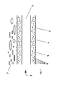
- a tube 1 according to the present invention is shown in a schematic cross-sectional view.
- the tube 1 is in this case formed by a wall 2 which limits a lumen 3.
- the wall 2 consists of polymer 5, wherein the polymer 5 contains polymer particles 6, which are distributed approximately homogeneously in the polymer 5.
- the wall 2 here represents the outer layer of the tube 1.
- Polymer particles 6 are arranged on the surface 4 of the wall 2 of the tube 1 such that they rise beyond the surface 4 to the outside, so cause a certain roughness of the surface 4 of the wall 2 on the outside of the tube 1.
- the polymer particles 6 are firmly bound to the surface 4 of the wall 2 of the tube 1 in the polymer 5.
- the tube 1 is embedded in a mineral mass 7, which is cured, the surface 4 rests against the mineral mass 7 gap-free and by means of the polymer particles 6, which are arranged on the surface 4 of the wall 2, with this mass. 7 is closely meshed.
Landscapes
- Chemical & Material Sciences (AREA)
- Health & Medical Sciences (AREA)
- Chemical Kinetics & Catalysis (AREA)
- Medicinal Chemistry (AREA)
- Polymers & Plastics (AREA)
- Organic Chemistry (AREA)
- Rigid Pipes And Flexible Pipes (AREA)
Description
- Die vorliegende Erfindung betrifft die Verwendung einer Polymer-Zusammensetzung zur Herstellung eines Rohres oder Rohrformteils, insbesondere zur Extrusion eines Rohres, sowie ein Rohr oder Rohrformteil, das unter Verwendung einer derartigen Polymer-Zusammensetzung erhalten worden ist.
- Im Stand der Technik bekannte Rohre oder Rohrformteil werden aus Polymer-Zusammensetzungen erhalten. Ziel ist es, eine möglichst glatte Oberfläche der Rohre oder Rohrformteile zu erhalten, um zu gewährleisten, dass die Rohre oder Rohrformteile einfach und sicher verlegbar sind.
- Rohrleitungen aus Polymermaterial werden häufig zur Wärmeübertragung von einem Fluid, das die Rohrleitung durchströmt, an ein Bauteil eingesetzt.
- Eine andere Anwendungsmöglichkeit ergibt sich dadurch, dass Rohrleitungen aus Polymermaterial in aushärtenden mineralischen Massen, wie beispielsweise Beton, Zement, Putz, Bentonit oder Estrich, verlegt werden.
- Dies ist besonders häufig im Rahmen von Wohnhäusern und Industriegebäuden anzutreffen.
- Weiterhin werden Rohrleitungen aus Polymermaterial häufig auch im Erdreich verlegt, um dort beispielsweise Erdwärme zu gewinnen oder aber Wärmeenergie in den Erdboden einzuspeisen.
- Hieraus ergeben sich typische Anwendungsfälle, wie beispielsweise Fußbodenheizungen bzw. Fußbodenkühlungen, Wand- oder Deckenheizungen und entsprechende Kühlungen, Betonkerntemperierungen, Rohrdurchführungen durch Wände, wie beispielsweise Hauseinführungen, Geothermiesonden, die vertikal oder schräg gebohrt sind, horizontale Erdkollektoren, Fermenterheizungen, Industrierohranlagen, etc..
- Insbesondere beim Verlegen von polymeren Rohrleitungen in aushärtenden mineralischen Massen, wie beispielsweise Beton, Zement, Putz, Bentonit oder Estrich, kommt es mit dem Abbinden, also dem Verfestigen dieser Massen, meist zu einer Volumenreduktion, wobei diese Massen schwinden.
- Da diese Massen an der Oberfläche der Rohrleitungen aus Polymermaterial schlecht anhaften, da diese glatt und hydrophob sind, entsteht dabei sehr häufig ein Ringspalt zwischen der ausgehärteten, oftmals geschwundenen Masse und der Oberfläche des Rohres aus Polymermaterial.
- Dieser Ringspalt bringt eine Reihe von Nachteilen mit sich.
- So ist zum einen die Wärmebertragung vom im Rohr geförderten Fluid zu der mineralischen Masse bzw. von der mineralischen Masse zum im Rohr strömenden Fluid erheblich behindert.
- Andererseits ist die Dichtigkeit, mit der das Rohr aus Polymermaterial in der mineralischen Masse eingebettet ist, deutlich verringert.
- Weiterhin kann dieser Spalt zwischen mineralischer Masse und Rohr aus Polymermaterial im Sinne eines durchgehenden offenen Kanals den Zutritt von Wasser bzw. Feuchtigkeit zu der ausgehärteten Masse begünstigen. Wenn dort Bewehrungsstellen, Anker oder sonstige Befestigungselemente eingebracht sind, wird deren Korrosion auf diese Weise massiv gefördert.
- Vor diesem Hintergrund liegt der vorliegenden Erfindung die Aufgabe zugrunde, die Verwendung einer Polymer-Zusammensetzung zur Herstellung von Rohren oder Rohrformteilen und entsprechende Rohre oder Rohrformteile zur Verfügung zu stellen, der die Nachteile des Standes der Technik überwinden.
- Insbesondere soll gemäß der vorliegenden Erfindung die Fähigkeit, die Rohre oder Rohrformteile an aushärtende mineralische Massen anzubinden, verbessert sein.
- Diese und andere Aufgaben werden durch die Verwendung einer Polymer-Zusammensetzung mit den Merkmalen des Anspruches 1 bzw. durch Rohre oder Rohrformteile mit den Merkmalen des Patentanspruchs 6 gelöst. Bevorzugte Ausführungsformen der vorliegenden Erfindung sind in den jeweils davon abhängigen Ansprüchen beschrieben.
- Gemäß der vorliegenden Erfindung wurde überraschenderweise erkannt, dass ein in Bezug auf die geschilderten Nachteiles von Rohren oder Rohrformteilen gemäß des Standes der Technik dann eine verbesserte Anbindung an mineralische aushärtende Massen erhalten wird, wenn der zur Herstellung der Rohre oder Rohrformteile verwendeten Polymer-Zusammensetzung neben dem Polymer auch Polymerpartikel in einer Menge von 5 Gewichtsteil bis 45 Gewichtsteilen, bezogen auf das Gesamtgewicht des Polymers und der Polymerpartikel, werden, wobei die Polymer-Zusammensetzung zur Herstellung wenigstens einer Außenschicht einer Wandung eines Rohres oder Rohrformteils eingesetzt wird.
- Der verbesserte Anbindungseffekt wird bei einem Anteil der Polymerpartikel unterhalb von 5 Gewichtsteil nicht mehr beobachtet, während ein Anteil der Polymerpartikel von mehr als 45 Gewichtsteilen zu einer verringerten Festigkeit der erfindungsgemäßen Rohre oder Rohrformteile führt.
- Dementsprechend liegt die vorliegende Erfindung in der Verwendung einer Polymer-Zusammensetzung, die
- (A) 55 Gewichtsteile bis 95 Gewichtsteile, bezogen auf das Gesamtgewicht der Komponenten (A) und (B), eines Polymers;
- (B) 5 Gewichtsteile bis 45 Gewichtsteile Polymerpartikel, bezogen auf das Gesamtgewicht der Komponenten (A) und (B), mit einem mittleren Partikeldurchmesser von 10 µm bis 250 µm; und ggf.
- (C) übliche Zusatzstoffe
- Die hierin beschriebenen Gewichtsanteile sind in Gewichtsteilen oder Gew.-% angegeben und beziehen sich jeweils auf das Gesamtgewicht des Komponenten (A) und (B) als 100 Gewichtsteile bzw. 100 Gew.-%.
- Als bevorzugte Materialien für das Polymer der Komponente (A) in der erfindungsgemäß verwendeten Polymer-Zusammensetzung haben sich thermoplastische Polymere wie Polyethylen (PE) oder Polypropylen (PP) oder ein Copolymeres des Polyethylens (PE) oder des Polypropylens (PP) oder Ethylvinylalkohol (EVOH) oder ein Gemisch aus Ethylvinylalkohol (EVOH) und Polyethylen (PE) oder ein maleinsäureanhydrid-gepfropftes Polyethylen (PE-MAH) oder ein maleinsäureanhydrid-gepfropftes Polypropylen (PP-MAH) sowie Gemische, Copolymere und Blends der genannten Polymere aus Gründen ihres bevorzugten Einsatzes zur Extrusion oder zur Spritzgussherstellung von Rohren oder Rohrformteilen erwiesen, wobei Polypropylen besonders bevorzugt ist.
- Als Materialien der Polymerpartikel der Komponente (B) sind ultrahochmolekulares Polyethylen (PE-UHMW) oder vernetztes Polyethylen (PE-X) bevorzugt, wobei insbesondere vernetzte Polymerpartikel aus dem Polymer des Polymermaterials der Komponente (A) aufgrund der jeweils guten Verträglichkeit mit dem Hauptmaterial der Polymer-Zusammensetzung besonders bevorzugt sind.
- Hinsichtlich der Menge der Polymerpartikel der Komponente (A) ist eine Menge von 5 Gewichtsteilen bis 45 Gewichtsteilen bezogen auf das Gesamtgewicht der Komponenten (A) und (B) insgesamt, in der Polymer-Zusammensetzung bevorzugt. Dementsprechend beträgt der Anteil des Polymers der Komponente (A) vorzugsweise 55 Gewichtsteile bis 95 Gewichtsteile, bezogen auf das Gesamtgewicht der Komponenten (A) und (B) insgesamt, in der Polymer-Zusammensetzung. Liegt der Gewichtsanteil der Polymerpartikel der Komponente (B) innerhalb dieser Grenzen, wird eine besonders günstige Anbindung an mineralische aushärtende Massen erreicht.
- Erfindungsgemäß weisen die Polymerpartikel der Komponente (B) einen mittleren Partikeldurchmesser von 10 µm bis 250 µm auf.
- Hinsichtlich des mittleren Partikeldurchmessers der Polymerpartikel der Komponente (B) ist es bevorzugt, dass dieser 50 µm bis 200 µm beträgt. Innerhalb dieses Bereichs wird ein besonders guter Anbindungseffekt an der Oberfläche eines solchen Rohres oder Rohrformteils erzielt.
- Ein mittlerer Partikeldurchmesser im Bereich von 80 µm bis 150 µm ist besonders bevorzugt. Hierbei resultiert ein ganz besonders starker Anbindungseffekt an der Oberfläche. Komponente (C) beschreibt übliche Zusatzstoffe, die in der erfindungsgemäß verwendeten Polymer-Zusammensetzung in wirksamen Mengen vorhanden sein können. Als übliche Zusatzstoffe können beispielsweise Verarbeitungsstabilisatoren (in einer Menge von 0,6 Gewichtsteilen bis 5 Gewichtsteilen, vorzugsweise etwa 2,5 Gewichtsteile; vorzugsweise Wärmestabilisatoren, vorzugsweise aus der Gruppe der Phosphite, und / oder UV-Stabilisatoren, und dergleichen), Gleitmittel (vorzugsweise in einer Menge von 0,01 Gewichtsteilen bis 3 Gewichtsteilen, insbesondere bevorzugt etwa 0,3 Gewichtsteile; beispielsweise Polyethylen- oder Polypropylenwachse, Esterwachse von Glykolen, Glycerin, Penta- und Dipentaerythrit oder anderen Polyolen mit geeigneten Carbonsäuren, Montanwachse, Paraffinwachse, Metallseifen und dergleichen), Pigmente (vorzugsweise in einer Menge von 0,01 Gewichtsteilen bis 6 Gewichtsteilen; beispielsweise Titandioxid, Calciumsulfat, Ultramarinblau, Ruße und dergleichen), polymere Verarbeitungshilfsstoffe (vorzugsweise in einer Menge von 0,1 Gewichtsteilen bis 2,5 Gewichtsteilen, besonders bevorzugt etwa 1,2 Gewichtsteile; beispielsweise Methylmethacrylat-Polymere und Copolymere), Strukturierungsmittel (in beliebigen Mengen; beispielsweise Glaskugeln, Epoxidharze, Acrylatharze und dergleichen), anorganische Füllstoffe oder Verstärkungsmittel (in einer Menge von 2 Gewichtsteilen bis 40 Gewichtsteilen, vorzugsweise etwa 15 Gewichtsteile; beispielsweise Kreide, Kalkstein, Marmor, Talkum, gefälltes Calciumcarbonat und dergleichen), Antistatika, UV-Absorber, Effektpigmente und dergleichen genannt werden. Darüber hinaus sind die wirksamen Mengen der möglichen Zusatzstoffe der Komponente (C) dem Fachmann bekannt. Die voranstehenden Gewichtsanteile beziehen sich wiederum jeweils auf die Summe der Komponenten (A) und (B) in der erfindungsgemäß verwendeten Polymer-Zusammensetzung als 100 Gewichtsteile.
- Die vorstehenden Ausführungen hinsichtlich der Materialen für die Komponente (A) und (B), der Gewichtsanteile der Komponenten (A) und (B), des mittleren Partikeldurchmessers der Polymerpartikel gemäß Komponente (B) sowie der üblichen Zusatzstoffe der Komponente (C) beziehen sich sowohl auf die erfindungsgemäße Verwendung der Polymer-Zusammensetzung als auch auf die erfindungsgemäßen Rohre und Rohrformteile.
- Die erfindungsgemäß verwendete Polymer-Zusammensetzung kann durch Mischen der Komponenten (A), (B) und ggf. (C) erfolgen. Dies geschieht zweckmäßigerweise entweder unmittelbar vor der Verarbeitung durch Vermischen der festen, pulverförmigen Komponenten (A), (B) und (C) der Polymer-Zusammensetzung in dem Fachmann geläufigen, marktüblichen Mischvorrichtungen oder in einem separaten Aufbereitungsschritt im Rahmen der Compoundherstellung. Bevorzugt werden die erfindungsgemäß verwendeten Polymer-Zusammensetzungen durch Extrudieren in marktüblichen Extrudern in dem Fachmann an sich bekannter Art und Weise zu Rohren und Rohrformteilen verarbeitet. Eine andere Fertigungstechnik ist das Spritzgießen und das Rotationsformen, womit ebenfalls Rohre und Rohrformteile zugänglich sind.
- Die auf diese Weise erhaltenen Rohre und Rohrformteile weisen eine matte, strukturierte Oberfläche auf und besitzen eine verbesserte Anbindung an mineralische aushärtende Massen.
- Während eines derartigen Extrusionsprozesses bleiben die Polymerpartikel der Komponente (B) vorzugsweise ungeschmolzen.
- Die Erfindung umfasst auch das Rohr oder Rohrformteil mit einer wenigstens aus einer Außenschicht gebildeten Wandung, geformt aus einer Polymerzusammensetzung, umfassend
- (A) 55 Gewichtsteile bis 95 Gewichtsteile, bezogen auf das Gesamtgewicht der Komponenten (A) und (B), eines Polymers;
- (B) 5 Gewichtsteile bis 45 Gewichtsteile Polymerpartikel, bezogen auf das Gesamtgewicht der Komponenten (A) und (B), mit einem mittleren Partikeldurchmesser von 10 µm bis 250 µm; und ggf.
- (C) übliche Zusatzstoffe.
- In einer vorteilhaften Ausbildung der Erfindung kann das Rohr oder Rohrformteil (1) derart gebildet sein, dass das Polymer der Komponente (A) Polyethylen (PE) oder Polypropylen (PP) oder ein Copolymeres des Polyethylens (PE) oder des Polypropylens (PP) oder ultrahochmolekulares Polyethylen oder vernetztes Polyethylen (PE-X) oder Ethylvinylalkohol (EVOH) oder ein Gemisch aus Ethylvinylalkohol (EVOH) und Polyethylen (PE) oder ein maleinsäureanhydrid-gepfropftes Polyethylen (PE-MAH) oder ein maleinsäureanhydrid-gepfropftes Polypropylen (PP-MAH) enthält oder ist und/oder die Polymerpartikel (6) der Komponente (B) ultrahochmolekulares Polyethylen (PE-UHMW) oder vernetztes Polyethylen (PE-X) enthalten oder daraus bestehen.
- In einer weiteren bevorzugten Ausbildung der Erfindung kann vorgesehen sein, dass die Polymerpartikel der Komponente (B) in einer Menge von 5 Gewichtsteilen bis 45 Gewichtsteilen, bezogen auf das Gesamtgewicht der Komponenten (A) und (B), in der Polymer-Zusammensetzung enthalten sind.
- In einer besonders günstigen Ausbildung der Erfindung kann vorgesehen sein, dass die
- Polymerpartikel der Komponente (B) in einer Menge von 10 Gewichtsteilen bis 30 Gewichtsteilen, bezogen auf das Gesamtgewicht der Komponenten (A) und (B), in der Polymer-Zusammensetzung enthalten sind.
- Eine weitere bevorzugte Ausbildung der Erfindung umfasst ein Rohr oder Rohrformteil, bei dem der mittlere Partikeldurchmesser der Polymerpartikel der Komponente (B) 50 µm bis 200 µm, insbesondere 80 µm bis 150 µm, beträgt.
- Es gelingt mit den erfindungsgemäßen Rohren oder Rohrformteilen, diese in mineralische aushärtende Massen derart einzubetten, dass nach dem Aushärten der mineralischen Masse diese spaltfrei oder zumindest überwiegend spaltfrei an der Oberfläche der Wandung der Rohre oder Rohrformteile anliegt.
- Damit ist dann in einer Art Labyrinthdichtung ein Leiten von Wasser oder Feuchtigkeit zwischen der Oberfläche des Rohres oder Rohrformteils und der anliegenden ausgehärteten Masse praktisch nicht mehr möglich.
- Das Rohr oder Rohrformteil ist in der ausgehärteten mineralischen Masse kraftschlüssig angeordnet, so dass Ausdehnungseffekte, die sich bei den Rohren oder Rohrformteilen dann ergeben, wenn diese beispielsweise bei einer Temperaturänderung des sie durchströmenden Fluids entsprechend erhitzt oder abgekühlt werden, nicht mehr auftreten. Dadurch lassen sich Bewegungen der Rohre oder Rohrformteile in der ausgehärteten Masse unter dem Einfluß von Temperaturänderungen vermeiden.
- Damit einher geht auch ein verbessernder Kontakt, insbesondere ein verbesserter Wärmeübertragungskontakt zwischen der Wandung des Rohres oder Rohrformteils und der anliegenden ausgehärteten mineralischen Masse.
- Dieser verbesserte Wärmeübergang ist insbesondere bei Erdwärmesonden-Rohranordnungen wichtig, da damit die Effizienz derartiger Anlagen deutlich gesteigert werden kann.
- Bei Erdwärmesonden-Rohranordnungen kommt als weiterer Effekt hinzu, dass durch die bereits geschilderte Dichtigkeit gegen die Leitung von Längswasser entlang der Rohroberfläche das erforderliche Trennen der verschiedenen Grundwasserhorizonte (Aquifere) im Erdboden in einem mit einer mineralischen aushärtenden Masse ausgefüllten Bohrloch dann mit hoher Sicherheit bewerkstelligt werden kann.
- Die Erfindung bringt es auch mit sich, dass beim Einbetten der Rohre oder Rohrformteile in aushärtende mineralische Massen nach der Aushärtung erhöhte Auszugskräfte resultieren, was bei Verlegearbeiten dieser Rohre oder Rohrformteile von Vorteil ist.
- Daneben bieten die erfindungsgemäßen Rohre oder Rohrformteile auch ein verbessertes Handling.
- Durch die Rauheit der Oberfläche der Rohre oder Rohrformteile gemäß vorliegender Erfindung liegt eine verminderte Gleitreibung vor, was beispielsweise das Einbringen des Rohres in das Bohrloch einer Erdwärmesondenbohrung erleichtert, indem dieses besser kontrolliert werden kann.
- Auch bei der Fixierung der erfindungsgemäßen Rohre oder Rohrformteile in den Aufnahmen beispielsweise einer Noppenplatte zur Herstellung einer Fußbodenheizung ist die vorliegende Erfindung hilfreich, da sich die Rohre lassen in diese Aufnahmen sicherer festlegen lassen.
- Es liegt im Rahmen der vorliegenden Erfindung, dass das erfindungsgemäße Rohr oder Rohrformteil noch weitere Schichten, und insbesondere Funktionsschichten aufweisen kann, die zumindest einen Teil der Wandung bilden.
- Es kann sich dabei um eine diffusionsreduzierende Schicht oder mehrere solcher Schichten handeln, weiterhin sind Verschleißschutzschichten vorteilhaft anzuordnen, die beispielsweise als dünne Schicht ausgebildet die äußerste Schicht des Rohres oder Rohrformteils darstellt und beispielsweise beim Einbau des Rohres vorteilhaft genutzt werden kann. Darüber hinaus sind Markierungsschichten und Indikatorschichten in einer günstigen Ausbildung der Erfindung vorsehbar, womit Informationen übermittelbar sind.
- So ist es beispielsweise möglich, im Rahmen der vorliegenden Erfindung ein Rohr zur Verfügung zu stellen, das einen mehrschichtigen Aufbau der Wandung aufweist, mit einem Innenrohr, das das Lumen des Rohres begrenzt, aus einem sehr resistenten Polymermaterial, wie beispielsweise vernetztes Polyethylen (PE-X), einer darauf folgenden Haftvermittlerschicht, einer darauf folgenden Schicht aus einem Metall, wie beispielsweise Aluminium, welches die Diffusion von Stoffen durch die Wandung begrenzt oder verhindert, einer darauf folgenden Schicht eines weiteren, ggf. zum vorstehenden unterschiedlichen Haftvermittlers, und schließlich einer äußeren Schicht, die unter Verwendung der Polymerzusammensetzung gemäß vorliegender Erfindung gebildet ist.
- Ein Rohr aus vernetzten Polyethylen (PE-X), das vorzugsweise peroxidisch vernetzt ist (PE-Xa) weist eine Schicht der Stärke 1 mm auf seiner äußeren Oberfläche auf, die unter Verwendung der Polymerzusammensetzung gemäß vorliegender Erfindung gebildet ist. Die Schicht enthält Polymer der Komponente (A), das Polyethylen (PE) ist und Polymerpartikel der Komponente (B) aus vernetztem Polyethylen (PE-X).
- Das Rohr weist eine außerordentlich feste Anbindung an aushärtende mineralische Massen auf.
- Anwendung findet die Erfindung überall dort, wo Rohre oder Rohrformteile in aushärtenden mineralischen Massen eingebettet werden und wo eine verbesserte Anbindung der Oberfläche der Rohre oder Rohrformteile an diese Massen erwünscht oder erforderlich ist.
- Dies betrifft beispielsweise Fußbodenheizungen bzw. Fußbodenkühlungen, Wand- oder Deckenheizungen und entsprechende Kühlungen, Betonkerntemperierungen, Rohrdurchführungen durch Wände, wie beispielsweise Hauseinführungen, Geothermiesonden, die vertikal oder schräg gebohrt sind, horizontale Erdkollektoren, thermisch aktivierte Tunnel- oder Schlitzwände, Fermenterheizungen, Industrierohranlagen, etc..
- Die Erfindung wird anhand der beigefügten Figur näher erläutert.
- Hierzu zeigt:
- Fig. 1
- eine schematische Querschnittansicht eines Rohres gemäß vorliegender Erfindung.
- In
Fig. 1 ist ein Rohr 1 gemäß vorliegender Erfindung in einer schematischen Querschnittansicht gezeigt. - Das Rohr 1 ist hierbei von einer Wandung 2 gebildet, die ein Lumen 3 begrenzt.
- Die Wandung 2 besteht aus Polymer 5, wobei das Polymer 5 Polymerpartikel 6 enthält, die in etwa homogen im Polymer 5 verteilt sind.
- Die Wandung 2 stellt hierbei die Außenschicht des Rohres 1 dar.
- Polymerpartikel 6 sind an der Oberfläche 4 der Wandung 2 des Rohres 1 derartig angeordnet, dass sie sich über die Oberfläche 4 nach außen hinaus erheben, also eine gewisse Rauigkeit der Oberfläche 4 der Wandung 2 an der Außenseite des Rohres 1 bewirken. Hierbei sind die Polymerpartikel 6 an der Oberfläche 4 der Wandung 2 des Rohres 1 fest im Polymer 5 eingebunden.
- Weiterhin ist in der
Fig.1 gezeigt, dass das Rohr 1 eingebettet ist in einer mineralischen Masse 7, die ausgehärtet ist, wobei die Oberfläche 4 spaltfrei an der mineralischen Masse 7 anliegt und mittels der Polymerpartikel 6, die an der Oberfläche 4 der Wandung 2 angeordnet sind, mit dieser Masse 7 eng verzahnt ist. -
- 1
- Rohr oder Rohrformteil
- 2
- Wandung
- 3
- Lumen
- 4
- Oberfläche
- 5
- Polymer
- 6
- Polymerpartikel
- 7
- mineralische ausgehärtete Masse
Claims (10)
- Verwendung einer Polymerzusammensetzung, umfassend(A) 55 Gewichtsteile bis 95 Gewichtsteile, bezogen auf das Gesamtgewicht der Komponenten (A) und (B), eines Polymers (5);(B) 5 Gewichtsteile bis 45 Gewichtsteile Polymerpartikel (6), bezogen auf das Gesamtgewicht der Komponenten (A) und (B), mit einem mittleren Partikeldurchmesser von 10 µm bis 250 µm; und ggf.(C) übliche Zusatzstoffezur Herstellung wenigstens einer Außenschicht einer Wandung (2) eines Rohres oder Rohrformteils (1).
- Verwendung nach Anspruch 1, dadurch gekennzeichnet, dass das Polymer (5) der Komponente (A) Polyethylen (PE) oder Polypropylen (PP) oder ein Copolymeres des Polyethylens (PE) oder des Polypropylens (PP) oder Ethylvinylalkohol (EVOH) oder ein Gemisch aus Ethylvinylalkohol (EVOH) und Polyethylen (PE) oder ein maleinsäureanhydrid-gepfropftes Polyethylen (PE-MAH) oder ein maleinsäureanhydrid-gepfropftes Polypropylen (PP-MAH) enthält oder ist.
- Verwendung nach Anspruch 1 oder 2, dadurch gekennzeichnet, dass die Polymerpartikel (6) der Komponente (B) ultrahochmolekulares Polyethylen (PE-UHMW) oder vernetztes Polyethylen (PE-X) enthalten oder daraus bestehen.
- Verwendung nach Anspruch 3, dadurch gekennzeichnet, dass die Polymerpartikel (6) der Komponente (B) in einer Menge von 10 Gewichtsteilen bis 30 Gewichtsteilen, bezogen auf das Gesamtgewicht der Komponenten (A) und (B), in der Polymer-Zusammensetzung enthalten sind.
- Verwendung nach einem der Ansprüche 1 bis 4, dadurch gekennzeichnet, dass der mittlere Partikeldurchmesser der Polymerpartikel (6) der Komponente (B) 50 µm bis 200 µm, insbesondere 80 µm bis 150 µm, beträgt.
- Rohr oder Rohrformteil (1) mit einer wenigstens aus einer Außenschicht gebildeten Wandung (2), geformt aus einer Polymerzusammensetzung, umfassend(A) 55 Gewichtsteile bis 95 Gewichtsteile, bezogen auf das Gesamtgewicht der Komponenten (A) und (B), eines Polymers (5);(B) 5 Gewichtsteile bis 45 Gewichtsteile Polymerpartikel (6), bezogen auf das Gesamtgewicht der Komponenten (A) und (B), mit einem mittleren Partikeldurchmesser von 10 µm bis 250 µm; und ggf.(C) übliche Zusatzstoffe.
- Rohr oder Rohrformteil (1) nach Anspruch 6, dadurch gekennzeichnet, dass das Polymer (5) der Komponente (A) Polyethylen (PE) oder Polypropylen (PP) oder ein Copolymeres des Polyethylens (PE) oder des Polypropylens (PP) oder ultrahochmolekulares Polyethylen oder vernetztes Polyethylen (PE-X) oder Ethylvinylalkohol (EVOH) oder ein Gemisch aus Ethylvinylalkohol (EVOH) und Polyethylen (PE) oder ein maleinsäureanhydrid-gepfropftes Polyethylen (PE-MAH) oder ein maleinsäureanhydrid-gepfropftes Polypropylen (PP-MAH) enthält oder ist und/oder die Polymerpartikel (6) der Komponente (B) ultrahochmolekulares Polyethylen (PE-UHMW) oder vernetztes Polyethylen (PE-X) enthalten oder daraus bestehen.
- Rohr oder Rohrformteil (1) nach Anspruch 6 oder 7, dadurch gekennzeichnet, dass die Polymerpartikel (6) der Komponente (B) in einer Menge von 5 Gewichtsteilen bis 45 Gewichtsteilen, bezogen auf das Gesamtgewicht der Komponenten (A) und (B), in der Polymer-Zusammensetzung enthalten sind.
- Rohr oder Rohrformteil (1) nach Anspruch 8, dadurch gekennzeichnet, dass die Polymerpartikel (6) der Komponente (B) in einer Menge von 10 Gewichtsteilen bis 30 Gewichtsteilen, bezogen auf das Gesamtgewicht der Komponenten (A) und (B), in der Polymer-Zusammensetzung enthalten sind.
- Rohr oder Rohrformteil (1) nach einem der Ansprüche 6 bis 9, dadurch gekennzeichnet, dass der mittlere Partikeldurchmesser der Polymerpartikel (6) der Komponente (B) 50 µm bis 200 µm, insbesondere 80 µm bis 150 µm, beträgt.
Priority Applications (1)
| Application Number | Priority Date | Filing Date | Title |
|---|---|---|---|
| PL13175262T PL2682424T3 (pl) | 2012-07-06 | 2013-07-05 | Zastosowanie zestawu polimerycznego |
Applications Claiming Priority (1)
| Application Number | Priority Date | Filing Date | Title |
|---|---|---|---|
| DE102012106061.4A DE102012106061A1 (de) | 2012-07-06 | 2012-07-06 | Verwendung einer Polymerzusammensetzung |
Publications (2)
| Publication Number | Publication Date |
|---|---|
| EP2682424A1 true EP2682424A1 (de) | 2014-01-08 |
| EP2682424B1 EP2682424B1 (de) | 2015-03-04 |
Family
ID=48875495
Family Applications (1)
| Application Number | Title | Priority Date | Filing Date |
|---|---|---|---|
| EP13175262.8A Active EP2682424B1 (de) | 2012-07-06 | 2013-07-05 | Verwendung einer Polymerzusammensetzung |
Country Status (3)
| Country | Link |
|---|---|
| EP (1) | EP2682424B1 (de) |
| DE (1) | DE102012106061A1 (de) |
| PL (1) | PL2682424T3 (de) |
Citations (4)
| Publication number | Priority date | Publication date | Assignee | Title |
|---|---|---|---|---|
| JPH10230555A (ja) * | 1997-02-19 | 1998-09-02 | Kuraray Co Ltd | 多層パイプおよびその用途 |
| EP1146273A1 (de) * | 1999-10-08 | 2001-10-17 | Kuraray Co., Ltd. | Rohr für heisswasserumwälzung |
| US6437048B1 (en) * | 1995-12-01 | 2002-08-20 | Chisso Corporation | Molded resin articles |
| DE202010017052U1 (de) * | 2010-12-24 | 2012-04-03 | Rehau Ag + Co. | Rohr oder Rohrformteil |
Family Cites Families (7)
| Publication number | Priority date | Publication date | Assignee | Title |
|---|---|---|---|---|
| SE9803501D0 (sv) * | 1998-10-14 | 1998-10-14 | Borealis Polymers Oy | Polymer composition for pipes |
| DE60025551T2 (de) * | 2000-04-13 | 2006-08-24 | Borealis Technology Oy | Polymerzusammensetzung für Rohre |
| DE602005008203D1 (de) * | 2005-05-06 | 2008-08-28 | Borealis Tech Oy | Polyethylenharz mit enger Korngrössenverteilung |
| US20060275571A1 (en) * | 2005-06-02 | 2006-12-07 | Mure Cliff R | Polyethylene pipes |
| PT1764385E (pt) * | 2005-09-15 | 2008-05-29 | Borealis Tech Oy | Tubo de pressão compreendendo uma composição de polietileno multimodal com um agente de enchimento inorgânico |
| ES2533868T3 (es) * | 2006-12-22 | 2015-04-15 | Ems-Chemie Ag | Conducto hidráulico, en particular conducto de embrague y procedimiento para su fabricación |
| DE202007010891U1 (de) * | 2007-08-03 | 2008-12-18 | Rehau Ag + Co | Rohr |
-
2012
- 2012-07-06 DE DE102012106061.4A patent/DE102012106061A1/de not_active Withdrawn
-
2013
- 2013-07-05 EP EP13175262.8A patent/EP2682424B1/de active Active
- 2013-07-05 PL PL13175262T patent/PL2682424T3/pl unknown
Patent Citations (4)
| Publication number | Priority date | Publication date | Assignee | Title |
|---|---|---|---|---|
| US6437048B1 (en) * | 1995-12-01 | 2002-08-20 | Chisso Corporation | Molded resin articles |
| JPH10230555A (ja) * | 1997-02-19 | 1998-09-02 | Kuraray Co Ltd | 多層パイプおよびその用途 |
| EP1146273A1 (de) * | 1999-10-08 | 2001-10-17 | Kuraray Co., Ltd. | Rohr für heisswasserumwälzung |
| DE202010017052U1 (de) * | 2010-12-24 | 2012-04-03 | Rehau Ag + Co. | Rohr oder Rohrformteil |
Also Published As
| Publication number | Publication date |
|---|---|
| EP2682424B1 (de) | 2015-03-04 |
| PL2682424T3 (pl) | 2015-08-31 |
| DE102012106061A1 (de) | 2014-01-09 |
Similar Documents
| Publication | Publication Date | Title |
|---|---|---|
| DE69318813T2 (de) | Verfahren zum Herstellen eines mehrschichtigen Kunststoffrohres und mehrschichtiges Kunststoffrohr zur Leitung von Fluiden | |
| EP3253722B1 (de) | Baustoffmischung | |
| EP1879703B2 (de) | Mehrlagige kunststoff-korrosionsschutzbeschichtung mit verbesserten eigenschaften | |
| EP2558764B1 (de) | Hausinstallationsrohrsystem sowie dessen verwendung | |
| EP2682424B1 (de) | Verwendung einer Polymerzusammensetzung | |
| DE2052043C3 (de) | Mischungen aus bitumenhaltigen Vakuumrückständen und/oder Vakuumgasölen und amorphen Polyolefinen zur Herstellung von Formkörpern | |
| DE2937057C2 (de) | Gußasphaltestrich zur Herstellung von Fußbodenaufbauten mit eingebetteten Heizrohren | |
| DE1298282C2 (de) | Mischungen auf der basis von bitumen zur herstellung von formkoerpern | |
| EP0059766B1 (de) | Gussasphalt-Estrichmasse für den Aufbau von beheizten Fussböden und Fussbodenaufbau mit dieser Gussasphalt-Estrichmasse | |
| WO2012031677A1 (de) | Kunststoffrohrformteil | |
| WO2004007161A1 (de) | Verfahren zur herstellung von textilbewehrten betonumhüllungen | |
| DE102013004325A1 (de) | Systemelement für Fußbodenheizung | |
| EP0894616B1 (de) | Rohr aus thermoplastischem Kunststoff | |
| EP1843103A2 (de) | Flüssigkeitsdurchflutete Mittel zum Temperieren von Räumen | |
| EP1536171B1 (de) | Mehrschichtige Kunststoffleitung mit PVC-Schicht | |
| DE102014108761A1 (de) | Verfahren zum Veredeln von Werkstoffen | |
| DE102022204037A1 (de) | Verwendung von einschichtigen Rohren, einschichtiges Rohr, Heizungsinstallation, Sanitärinstallation und Klimaanlageninstallation | |
| DE3932743C1 (en) | Sound damping plaster compsn. - of quartz sand and poly-satd. polybutadiene binder | |
| DE202009011917U1 (de) | Mehrschichtiger Schrumpfschlauch | |
| DE202011100453U1 (de) | Mehrschichtiger Belag | |
| DE1784522A1 (de) | Verfahren zum Auskleiden von Druckstollen oder Druckschaechten | |
| EP1526313B1 (de) | Rohrleitung und Verfahren zur Herstellung | |
| EP0428929A1 (de) | Verbundkörper aus einem Grundkörper aus einem Baustoff oder einem Kunststoff und einem ausgehärteten Polyesterharz | |
| DE10200464A1 (de) | Rohr oder Rohrformstück mit verbesserten Wärmedämm- und/oder Stabilitäts- und Festigkeitseigenschaften sowie Verfahren zur Herstellung derartiger Rohre oder -formstücke | |
| DE202010017052U1 (de) | Rohr oder Rohrformteil |
Legal Events
| Date | Code | Title | Description |
|---|---|---|---|
| PUAI | Public reference made under article 153(3) epc to a published international application that has entered the european phase |
Free format text: ORIGINAL CODE: 0009012 |
|
| AK | Designated contracting states |
Kind code of ref document: A1 Designated state(s): AL AT BE BG CH CY CZ DE DK EE ES FI FR GB GR HR HU IE IS IT LI LT LU LV MC MK MT NL NO PL PT RO RS SE SI SK SM TR |
|
| AX | Request for extension of the european patent |
Extension state: BA ME |
|
| 17P | Request for examination filed |
Effective date: 20140306 |
|
| RAX | Requested extension states of the european patent have changed |
Extension state: BA Payment date: 20140306 Extension state: ME Payment date: 20140306 |
|
| RBV | Designated contracting states (corrected) |
Designated state(s): AL AT BE BG CH CY CZ DE DK EE ES FI FR GB GR HR HU IE IS IT LI LT LU LV MC MK MT NL NO PL PT RO RS SE SI SK SM TR |
|
| GRAP | Despatch of communication of intention to grant a patent |
Free format text: ORIGINAL CODE: EPIDOSNIGR1 |
|
| INTG | Intention to grant announced |
Effective date: 20141128 |
|
| GRAS | Grant fee paid |
Free format text: ORIGINAL CODE: EPIDOSNIGR3 |
|
| GRAA | (expected) grant |
Free format text: ORIGINAL CODE: 0009210 |
|
| AK | Designated contracting states |
Kind code of ref document: B1 Designated state(s): AL AT BE BG CH CY CZ DE DK EE ES FI FR GB GR HR HU IE IS IT LI LT LU LV MC MK MT NL NO PL PT RO RS SE SI SK SM TR |
|
| AX | Request for extension of the european patent |
Extension state: BA ME |
|
| REG | Reference to a national code |
Ref country code: GB Ref legal event code: FG4D Free format text: NOT ENGLISH |
|
| REG | Reference to a national code |
Ref country code: CH Ref legal event code: EP |
|
| REG | Reference to a national code |
Ref country code: IE Ref legal event code: FG4D Free format text: LANGUAGE OF EP DOCUMENT: GERMAN |
|
| REG | Reference to a national code |
Ref country code: AT Ref legal event code: REF Ref document number: 713865 Country of ref document: AT Kind code of ref document: T Effective date: 20150415 |
|
| REG | Reference to a national code |
Ref country code: DE Ref legal event code: R096 Ref document number: 502013000405 Country of ref document: DE Effective date: 20150416 |
|
| REG | Reference to a national code |
Ref country code: NL Ref legal event code: T3 |
|
| PG25 | Lapsed in a contracting state [announced via postgrant information from national office to epo] |
Ref country code: NO Free format text: LAPSE BECAUSE OF FAILURE TO SUBMIT A TRANSLATION OF THE DESCRIPTION OR TO PAY THE FEE WITHIN THE PRESCRIBED TIME-LIMIT Effective date: 20150604 Ref country code: SE Free format text: LAPSE BECAUSE OF FAILURE TO SUBMIT A TRANSLATION OF THE DESCRIPTION OR TO PAY THE FEE WITHIN THE PRESCRIBED TIME-LIMIT Effective date: 20150304 Ref country code: HR Free format text: LAPSE BECAUSE OF FAILURE TO SUBMIT A TRANSLATION OF THE DESCRIPTION OR TO PAY THE FEE WITHIN THE PRESCRIBED TIME-LIMIT Effective date: 20150304 Ref country code: LT Free format text: LAPSE BECAUSE OF FAILURE TO SUBMIT A TRANSLATION OF THE DESCRIPTION OR TO PAY THE FEE WITHIN THE PRESCRIBED TIME-LIMIT Effective date: 20150304 Ref country code: ES Free format text: LAPSE BECAUSE OF FAILURE TO SUBMIT A TRANSLATION OF THE DESCRIPTION OR TO PAY THE FEE WITHIN THE PRESCRIBED TIME-LIMIT Effective date: 20150304 Ref country code: FI Free format text: LAPSE BECAUSE OF FAILURE TO SUBMIT A TRANSLATION OF THE DESCRIPTION OR TO PAY THE FEE WITHIN THE PRESCRIBED TIME-LIMIT Effective date: 20150304 |
|
| REG | Reference to a national code |
Ref country code: LT Ref legal event code: MG4D |
|
| PG25 | Lapsed in a contracting state [announced via postgrant information from national office to epo] |
Ref country code: LV Free format text: LAPSE BECAUSE OF FAILURE TO SUBMIT A TRANSLATION OF THE DESCRIPTION OR TO PAY THE FEE WITHIN THE PRESCRIBED TIME-LIMIT Effective date: 20150304 Ref country code: RS Free format text: LAPSE BECAUSE OF FAILURE TO SUBMIT A TRANSLATION OF THE DESCRIPTION OR TO PAY THE FEE WITHIN THE PRESCRIBED TIME-LIMIT Effective date: 20150304 Ref country code: GR Free format text: LAPSE BECAUSE OF FAILURE TO SUBMIT A TRANSLATION OF THE DESCRIPTION OR TO PAY THE FEE WITHIN THE PRESCRIBED TIME-LIMIT Effective date: 20150605 |
|
| REG | Reference to a national code |
Ref country code: PL Ref legal event code: T3 |
|
| PG25 | Lapsed in a contracting state [announced via postgrant information from national office to epo] |
Ref country code: RO Free format text: LAPSE BECAUSE OF FAILURE TO SUBMIT A TRANSLATION OF THE DESCRIPTION OR TO PAY THE FEE WITHIN THE PRESCRIBED TIME-LIMIT Effective date: 20150304 Ref country code: EE Free format text: LAPSE BECAUSE OF FAILURE TO SUBMIT A TRANSLATION OF THE DESCRIPTION OR TO PAY THE FEE WITHIN THE PRESCRIBED TIME-LIMIT Effective date: 20150304 Ref country code: CZ Free format text: LAPSE BECAUSE OF FAILURE TO SUBMIT A TRANSLATION OF THE DESCRIPTION OR TO PAY THE FEE WITHIN THE PRESCRIBED TIME-LIMIT Effective date: 20150304 Ref country code: SK Free format text: LAPSE BECAUSE OF FAILURE TO SUBMIT A TRANSLATION OF THE DESCRIPTION OR TO PAY THE FEE WITHIN THE PRESCRIBED TIME-LIMIT Effective date: 20150304 Ref country code: PT Free format text: LAPSE BECAUSE OF FAILURE TO SUBMIT A TRANSLATION OF THE DESCRIPTION OR TO PAY THE FEE WITHIN THE PRESCRIBED TIME-LIMIT Effective date: 20150706 |
|
| PG25 | Lapsed in a contracting state [announced via postgrant information from national office to epo] |
Ref country code: IS Free format text: LAPSE BECAUSE OF FAILURE TO SUBMIT A TRANSLATION OF THE DESCRIPTION OR TO PAY THE FEE WITHIN THE PRESCRIBED TIME-LIMIT Effective date: 20150704 |
|
| REG | Reference to a national code |
Ref country code: DE Ref legal event code: R097 Ref document number: 502013000405 Country of ref document: DE |
|
| PLBE | No opposition filed within time limit |
Free format text: ORIGINAL CODE: 0009261 |
|
| STAA | Information on the status of an ep patent application or granted ep patent |
Free format text: STATUS: NO OPPOSITION FILED WITHIN TIME LIMIT |
|
| PG25 | Lapsed in a contracting state [announced via postgrant information from national office to epo] |
Ref country code: DK Free format text: LAPSE BECAUSE OF FAILURE TO SUBMIT A TRANSLATION OF THE DESCRIPTION OR TO PAY THE FEE WITHIN THE PRESCRIBED TIME-LIMIT Effective date: 20150304 |
|
| 26N | No opposition filed |
Effective date: 20151207 |
|
| PG25 | Lapsed in a contracting state [announced via postgrant information from national office to epo] |
Ref country code: MC Free format text: LAPSE BECAUSE OF FAILURE TO SUBMIT A TRANSLATION OF THE DESCRIPTION OR TO PAY THE FEE WITHIN THE PRESCRIBED TIME-LIMIT Effective date: 20150304 Ref country code: SI Free format text: LAPSE BECAUSE OF FAILURE TO SUBMIT A TRANSLATION OF THE DESCRIPTION OR TO PAY THE FEE WITHIN THE PRESCRIBED TIME-LIMIT Effective date: 20150304 |
|
| PG25 | Lapsed in a contracting state [announced via postgrant information from national office to epo] |
Ref country code: LU Free format text: LAPSE BECAUSE OF FAILURE TO SUBMIT A TRANSLATION OF THE DESCRIPTION OR TO PAY THE FEE WITHIN THE PRESCRIBED TIME-LIMIT Effective date: 20150705 |
|
| REG | Reference to a national code |
Ref country code: IE Ref legal event code: MM4A |
|
| REG | Reference to a national code |
Ref country code: FR Ref legal event code: PLFP Year of fee payment: 4 |
|
| PG25 | Lapsed in a contracting state [announced via postgrant information from national office to epo] |
Ref country code: IE Free format text: LAPSE BECAUSE OF NON-PAYMENT OF DUE FEES Effective date: 20150705 |
|
| PG25 | Lapsed in a contracting state [announced via postgrant information from national office to epo] |
Ref country code: MT Free format text: LAPSE BECAUSE OF FAILURE TO SUBMIT A TRANSLATION OF THE DESCRIPTION OR TO PAY THE FEE WITHIN THE PRESCRIBED TIME-LIMIT Effective date: 20150304 |
|
| PG25 | Lapsed in a contracting state [announced via postgrant information from national office to epo] |
Ref country code: BG Free format text: LAPSE BECAUSE OF FAILURE TO SUBMIT A TRANSLATION OF THE DESCRIPTION OR TO PAY THE FEE WITHIN THE PRESCRIBED TIME-LIMIT Effective date: 20150304 Ref country code: HU Free format text: LAPSE BECAUSE OF FAILURE TO SUBMIT A TRANSLATION OF THE DESCRIPTION OR TO PAY THE FEE WITHIN THE PRESCRIBED TIME-LIMIT; INVALID AB INITIO Effective date: 20130705 |
|
| PG25 | Lapsed in a contracting state [announced via postgrant information from national office to epo] |
Ref country code: CY Free format text: LAPSE BECAUSE OF FAILURE TO SUBMIT A TRANSLATION OF THE DESCRIPTION OR TO PAY THE FEE WITHIN THE PRESCRIBED TIME-LIMIT Effective date: 20150304 |
|
| REG | Reference to a national code |
Ref country code: FR Ref legal event code: PLFP Year of fee payment: 5 |
|
| PG25 | Lapsed in a contracting state [announced via postgrant information from national office to epo] |
Ref country code: SM Free format text: LAPSE BECAUSE OF FAILURE TO SUBMIT A TRANSLATION OF THE DESCRIPTION OR TO PAY THE FEE WITHIN THE PRESCRIBED TIME-LIMIT Effective date: 20150304 |
|
| PG25 | Lapsed in a contracting state [announced via postgrant information from national office to epo] |
Ref country code: MK Free format text: LAPSE BECAUSE OF FAILURE TO SUBMIT A TRANSLATION OF THE DESCRIPTION OR TO PAY THE FEE WITHIN THE PRESCRIBED TIME-LIMIT Effective date: 20150304 Ref country code: TR Free format text: LAPSE BECAUSE OF FAILURE TO SUBMIT A TRANSLATION OF THE DESCRIPTION OR TO PAY THE FEE WITHIN THE PRESCRIBED TIME-LIMIT Effective date: 20150304 |
|
| REG | Reference to a national code |
Ref country code: FR Ref legal event code: PLFP Year of fee payment: 6 |
|
| PG25 | Lapsed in a contracting state [announced via postgrant information from national office to epo] |
Ref country code: AL Free format text: LAPSE BECAUSE OF FAILURE TO SUBMIT A TRANSLATION OF THE DESCRIPTION OR TO PAY THE FEE WITHIN THE PRESCRIBED TIME-LIMIT Effective date: 20150304 |
|
| PGFP | Annual fee paid to national office [announced via postgrant information from national office to epo] |
Ref country code: FR Payment date: 20180703 Year of fee payment: 6 Ref country code: NL Payment date: 20180628 Year of fee payment: 6 |
|
| PGFP | Annual fee paid to national office [announced via postgrant information from national office to epo] |
Ref country code: SE Payment date: 20180910 Year of fee payment: 8 |
|
| GBPC | Gb: european patent ceased through non-payment of renewal fee |
Effective date: 20190705 |
|
| REG | Reference to a national code |
Ref country code: BE Ref legal event code: MM Effective date: 20190731 |
|
| PG25 | Lapsed in a contracting state [announced via postgrant information from national office to epo] |
Ref country code: NL Free format text: LAPSE BECAUSE OF NON-PAYMENT OF DUE FEES Effective date: 20190801 Ref country code: GB Free format text: LAPSE BECAUSE OF NON-PAYMENT OF DUE FEES Effective date: 20190705 |
|
| REG | Reference to a national code |
Ref country code: NL Ref legal event code: MM Effective date: 20190801 |
|
| PG25 | Lapsed in a contracting state [announced via postgrant information from national office to epo] |
Ref country code: BE Free format text: LAPSE BECAUSE OF NON-PAYMENT OF DUE FEES Effective date: 20190731 |
|
| PG25 | Lapsed in a contracting state [announced via postgrant information from national office to epo] |
Ref country code: FR Free format text: LAPSE BECAUSE OF NON-PAYMENT OF DUE FEES Effective date: 20190731 |
|
| PGFP | Annual fee paid to national office [announced via postgrant information from national office to epo] |
Ref country code: PL Payment date: 20210519 Year of fee payment: 9 |
|
| PGFP | Annual fee paid to national office [announced via postgrant information from national office to epo] |
Ref country code: AT Payment date: 20210705 Year of fee payment: 9 |
|
| PGFP | Annual fee paid to national office [announced via postgrant information from national office to epo] |
Ref country code: CH Payment date: 20210707 Year of fee payment: 9 |
|
| REG | Reference to a national code |
Ref country code: DE Ref legal event code: R081 Ref document number: 502013000405 Country of ref document: DE Owner name: REHAU INDUSTRIES SE & CO. KG, DE Free format text: FORMER OWNER: REHAU AG & CO, 95111 REHAU, DE |
|
| REG | Reference to a national code |
Ref country code: AT Ref legal event code: PC Ref document number: 713865 Country of ref document: AT Kind code of ref document: T Owner name: REHAU INDUSTRIES SE & CO. KG, DE Effective date: 20220419 |
|
| REG | Reference to a national code |
Ref country code: CH Ref legal event code: PL |
|
| REG | Reference to a national code |
Ref country code: AT Ref legal event code: MM01 Ref document number: 713865 Country of ref document: AT Kind code of ref document: T Effective date: 20220705 |
|
| PG25 | Lapsed in a contracting state [announced via postgrant information from national office to epo] |
Ref country code: LI Free format text: LAPSE BECAUSE OF NON-PAYMENT OF DUE FEES Effective date: 20220731 Ref country code: CH Free format text: LAPSE BECAUSE OF NON-PAYMENT OF DUE FEES Effective date: 20220731 Ref country code: AT Free format text: LAPSE BECAUSE OF NON-PAYMENT OF DUE FEES Effective date: 20220705 |
|
| PG25 | Lapsed in a contracting state [announced via postgrant information from national office to epo] |
Ref country code: PL Free format text: LAPSE BECAUSE OF NON-PAYMENT OF DUE FEES Effective date: 20220705 |
|
| PGFP | Annual fee paid to national office [announced via postgrant information from national office to epo] |
Ref country code: DE Payment date: 20250731 Year of fee payment: 13 |
|
| PGFP | Annual fee paid to national office [announced via postgrant information from national office to epo] |
Ref country code: IT Payment date: 20250730 Year of fee payment: 13 |