EP2682139A1 - Haltevorrichtung und medizinisches Gerät zur extrakorporalen Blutbehandlung mit Haltevorrichtung - Google Patents
Haltevorrichtung und medizinisches Gerät zur extrakorporalen Blutbehandlung mit Haltevorrichtung Download PDFInfo
- Publication number
- EP2682139A1 EP2682139A1 EP13174677.8A EP13174677A EP2682139A1 EP 2682139 A1 EP2682139 A1 EP 2682139A1 EP 13174677 A EP13174677 A EP 13174677A EP 2682139 A1 EP2682139 A1 EP 2682139A1
- Authority
- EP
- European Patent Office
- Prior art keywords
- holder
- holding device
- component
- pivoting
- housing
- Prior art date
- Legal status (The legal status is an assumption and is not a legal conclusion. Google has not performed a legal analysis and makes no representation as to the accuracy of the status listed.)
- Granted
Links
Images


Classifications
-
- A—HUMAN NECESSITIES
- A61—MEDICAL OR VETERINARY SCIENCE; HYGIENE
- A61M—DEVICES FOR INTRODUCING MEDIA INTO, OR ONTO, THE BODY; DEVICES FOR TRANSDUCING BODY MEDIA OR FOR TAKING MEDIA FROM THE BODY; DEVICES FOR PRODUCING OR ENDING SLEEP OR STUPOR
- A61M1/00—Suction or pumping devices for medical purposes; Devices for carrying-off, for treatment of, or for carrying-over, body-liquids; Drainage systems
- A61M1/14—Dialysis systems; Artificial kidneys; Blood oxygenators ; Reciprocating systems for treatment of body fluids, e.g. single needle systems for hemofiltration or pheresis
- A61M1/16—Dialysis systems; Artificial kidneys; Blood oxygenators ; Reciprocating systems for treatment of body fluids, e.g. single needle systems for hemofiltration or pheresis with membranes
-
- A—HUMAN NECESSITIES
- A61—MEDICAL OR VETERINARY SCIENCE; HYGIENE
- A61B—DIAGNOSIS; SURGERY; IDENTIFICATION
- A61B50/00—Containers, covers, furniture or holders specially adapted for surgical or diagnostic appliances or instruments, e.g. sterile covers
- A61B50/20—Holders specially adapted for surgical or diagnostic appliances or instruments
-
- F—MECHANICAL ENGINEERING; LIGHTING; HEATING; WEAPONS; BLASTING
- F16—ENGINEERING ELEMENTS AND UNITS; GENERAL MEASURES FOR PRODUCING AND MAINTAINING EFFECTIVE FUNCTIONING OF MACHINES OR INSTALLATIONS; THERMAL INSULATION IN GENERAL
- F16M—FRAMES, CASINGS OR BEDS OF ENGINES, MACHINES OR APPARATUS, NOT SPECIFIC TO ENGINES, MACHINES OR APPARATUS PROVIDED FOR ELSEWHERE; STANDS; SUPPORTS
- F16M11/00—Stands or trestles as supports for apparatus or articles placed thereon ; Stands for scientific apparatus such as gravitational force meters
- F16M11/02—Heads
- F16M11/04—Means for attachment of apparatus; Means allowing adjustment of the apparatus relatively to the stand
- F16M11/06—Means for attachment of apparatus; Means allowing adjustment of the apparatus relatively to the stand allowing pivoting
-
- F—MECHANICAL ENGINEERING; LIGHTING; HEATING; WEAPONS; BLASTING
- F16—ENGINEERING ELEMENTS AND UNITS; GENERAL MEASURES FOR PRODUCING AND MAINTAINING EFFECTIVE FUNCTIONING OF MACHINES OR INSTALLATIONS; THERMAL INSULATION IN GENERAL
- F16M—FRAMES, CASINGS OR BEDS OF ENGINES, MACHINES OR APPARATUS, NOT SPECIFIC TO ENGINES, MACHINES OR APPARATUS PROVIDED FOR ELSEWHERE; STANDS; SUPPORTS
- F16M11/00—Stands or trestles as supports for apparatus or articles placed thereon ; Stands for scientific apparatus such as gravitational force meters
- F16M11/02—Heads
- F16M11/04—Means for attachment of apparatus; Means allowing adjustment of the apparatus relatively to the stand
- F16M11/06—Means for attachment of apparatus; Means allowing adjustment of the apparatus relatively to the stand allowing pivoting
- F16M11/10—Means for attachment of apparatus; Means allowing adjustment of the apparatus relatively to the stand allowing pivoting around a horizontal axis
-
- F—MECHANICAL ENGINEERING; LIGHTING; HEATING; WEAPONS; BLASTING
- F16—ENGINEERING ELEMENTS AND UNITS; GENERAL MEASURES FOR PRODUCING AND MAINTAINING EFFECTIVE FUNCTIONING OF MACHINES OR INSTALLATIONS; THERMAL INSULATION IN GENERAL
- F16M—FRAMES, CASINGS OR BEDS OF ENGINES, MACHINES OR APPARATUS, NOT SPECIFIC TO ENGINES, MACHINES OR APPARATUS PROVIDED FOR ELSEWHERE; STANDS; SUPPORTS
- F16M11/00—Stands or trestles as supports for apparatus or articles placed thereon ; Stands for scientific apparatus such as gravitational force meters
- F16M11/02—Heads
- F16M11/04—Means for attachment of apparatus; Means allowing adjustment of the apparatus relatively to the stand
- F16M11/06—Means for attachment of apparatus; Means allowing adjustment of the apparatus relatively to the stand allowing pivoting
- F16M11/10—Means for attachment of apparatus; Means allowing adjustment of the apparatus relatively to the stand allowing pivoting around a horizontal axis
- F16M11/105—Means for attachment of apparatus; Means allowing adjustment of the apparatus relatively to the stand allowing pivoting around a horizontal axis the horizontal axis being the roll axis, e.g. for creating a landscape-portrait rotation
-
- F—MECHANICAL ENGINEERING; LIGHTING; HEATING; WEAPONS; BLASTING
- F16—ENGINEERING ELEMENTS AND UNITS; GENERAL MEASURES FOR PRODUCING AND MAINTAINING EFFECTIVE FUNCTIONING OF MACHINES OR INSTALLATIONS; THERMAL INSULATION IN GENERAL
- F16M—FRAMES, CASINGS OR BEDS OF ENGINES, MACHINES OR APPARATUS, NOT SPECIFIC TO ENGINES, MACHINES OR APPARATUS PROVIDED FOR ELSEWHERE; STANDS; SUPPORTS
- F16M13/00—Other supports for positioning apparatus or articles; Means for steadying hand-held apparatus or articles
- F16M13/02—Other supports for positioning apparatus or articles; Means for steadying hand-held apparatus or articles for supporting on, or attaching to, an object, e.g. tree, gate, window-frame, cycle
- F16M13/022—Other supports for positioning apparatus or articles; Means for steadying hand-held apparatus or articles for supporting on, or attaching to, an object, e.g. tree, gate, window-frame, cycle repositionable
-
- A—HUMAN NECESSITIES
- A61—MEDICAL OR VETERINARY SCIENCE; HYGIENE
- A61G—TRANSPORT, PERSONAL CONVEYANCES, OR ACCOMMODATION SPECIALLY ADAPTED FOR PATIENTS OR DISABLED PERSONS; OPERATING TABLES OR CHAIRS; CHAIRS FOR DENTISTRY; FUNERAL DEVICES
- A61G7/00—Beds specially adapted for nursing; Devices for lifting patients or disabled persons
- A61G7/05—Parts, details or accessories of beds
- A61G7/0503—Holders, support devices for receptacles, e.g. for drainage or urine bags
-
- A—HUMAN NECESSITIES
- A61—MEDICAL OR VETERINARY SCIENCE; HYGIENE
- A61M—DEVICES FOR INTRODUCING MEDIA INTO, OR ONTO, THE BODY; DEVICES FOR TRANSDUCING BODY MEDIA OR FOR TAKING MEDIA FROM THE BODY; DEVICES FOR PRODUCING OR ENDING SLEEP OR STUPOR
- A61M2209/00—Ancillary equipment
- A61M2209/08—Supports for equipment
- A61M2209/082—Mounting brackets, arm supports for equipment
Definitions
- the invention relates to a holding device for a medical device, comprising a holder and a second component, on which the holder is mounted, wherein the holder has a receptacle on which a functional part is releasably insertable.
- the invention further relates to a medical device for extracorporeal blood treatment with such a holding device.
- filters are used, which allow the Stoffausstauch. These filters can be attached or held on the medical device. Conventionally, these holders are arranged for handling reasons at exposed locations, and designed to be movable.
- the object of the invention is therefore to provide a robust holder for a medical functional part, which prevents incorrect operation.
- the object of the invention is also to provide a medical device for extracorporeal blood treatment with such a holder.
- this object is achieved by a holding device according to independent claim 1. Advantageous developments of the holding device will become apparent from the dependent claims 2-8.
- the object is further achieved by a medical device for extracorporeal blood treatment according to claims 9 and 10.
- the holding device according to the invention for a medical device in this case comprises a holder and a second component to which the holder is attached or with which the holder can be coupled, wherein the holder has a receptacle on which a functional part is releasably insertable or connectable.
- the second component in this case has a recess, within which a holder is mounted, which is spring-loaded relative to the second component movable.
- the holder is in turn pivotally mounted about an axis of rotation on the holder, wherein a tensile force can be applied to the holder by the spring-loaded holder.
- the holder or the recess is formed so that when pivoting the holder about the rotation axis, a pivot portion of the holder moves within the recess, while the receptacle protrudes from the recess.
- the robustness of the holding device can be increased because the resilient connection of the holder on the second component protects both components from damage. Further, the holder can be pivoted about an axis of rotation, which can be intended, but can also be effected unintentionally. Intended pivotal movements allow the targeted positioning of the holder in a certain position, and in case of accidental shocks pivots the holder, without causing any cracks or breaks in components.
- the second component is, for example, a medical device for extracorporeal blood treatment or the housing of such a medical device
- a dialyzer or a holder for receiving a dialyzer can be attached to the holding device.
- the holder When passing through bottlenecks, the holder can not be traversed, and there is no damage to the medical device.
- the area between the pivot portion of the holder and the recess is bridged by a cover or even sealed by a seal.
- a holder for receiving a functional part at a suitable location in the field of action of an operator can be integrated, whereby incorrect operation is prevented.
- the holder is further integrated into the second component so that it can not be stolen.
- the operation of a medical device can thus not be affected by a missing holder.
- it is also possible to integrate other elements such as hose holder in the holder, for example, to be able to accommodate drip chambers and / or hoses.
- the second component has means with which the pivoting of the holder between two defined end positions can be limited.
- two stops may be formed on the second component, which come in the two defined end positions, each with a stop surface on the pivot portion of the holder in contact.
- the stops are preferably designed to stop the pivotal movement of the holder before it contacts housing parts that could otherwise be damaged. This is in particular the outer edge of the recess in the housing, within which the holding device is mounted. Because if the holder would hit this edge when panning it could cause a break.
- the pivotal attachment of the holder on the second component can be done for example via a connecting bolt or hinge pin, which is guided by an eye of the holder, wherein the two end portions of the connecting bolt are respectively inserted into a receptacle on the second component.
- an axis of rotation can be formed around which the holder is pivotable.
- the receptacles are on a mounting plate which is detachably attached to the second component.
- a mounting plate has in particular the Advantage that the required geometry of the holding device does not have to be formed in the housing, which facilitates the manufacture of the housing. Rather, the mounting plate can be formed accordingly and screwed to the housing.
- the screw-on also consist of a different material than the second component and / or the holder.
- a friction brake or grinding brake is provided on the holding device, with which the pivoting movement of the holder can be braked about the axis of rotation.
- This has the advantage of slowing down both intentional and unintended panning movements, further reducing the risk of component damage.
- at least two plate-shaped or disc-shaped brake elements may be formed on the pivoting section so that they permanently contact the holder when the holder is pivoted, the brake elements resting on two opposing sides on the holder and extending transversely to the axis of rotation.
- the invention further comprises a medical device for extracorporeal blood treatment, which has a housing and a holding device with a holder for receiving a functional part of the medical device, wherein the holding device is designed according to the invention.
- the male functional part can then be for example a dialyzer or another holder for receiving the dialyzer.
- Such a medical device can use the advantages of the holding device according to the invention and is particularly protected against damage.
- the holding device can also be provided on other medical devices in which a robust support for a functional part is to be provided.
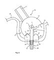
- Fig. 1 shows an embodiment of a holding device according to the invention, which is integrated in a second component 20.
- the second component 20 is, for example, the housing of a medical device, which may be, in particular, a medical device for extracorporeal blood treatment, to which a functional part, such as a filter or dialyzer, is attached for therapy.
- a medical device for extracorporeal blood treatment
- a functional part such as a filter or dialyzer
- Fig. 1 shows a schematic section across the pivot axis 11 of a holder 10, wherein only the section of the housing 20 is shown, in which the holder 30 is mounted. This may, for example, be the corner region of a housing.
- the holding device comprises the holder 10, which is designed to receive directly or indirectly a functional part of the medical device.
- a receptacle or a receiving portion 12 is provided on the holder 10, which is formed in the illustrated embodiment so that a filter holder 12 is inserted into the hollow cylindrical receptacle.
- the dialyzer can be introduced.
- a filter holder is axially within the Receive 12 lockable, but at the same time rotatably mounted, so that the filter holder can be rotated within the receptacle 12.
- the receptacle 12 can also be designed directly as a filter holder, in which a dialyzer is releasably introduced, so that the filter can be removed after use again from the holding device.
- the holder 10 in this case is preferably made of plastic.
- a chamber holder and / or a hose holder can be additionally attached or integrally formed on the holder 10.
- the holding device comprises a recess 21, in which the holder 10 is pivotally integrated.
- the recess 21 is located in the embodiment of the figures in a corner region of the housing 20, so that this corner is formed as a holding device.
- the holder 10 is divided into a pivot portion 13 and the receptacle 12, wherein the pivot portion 13 is within or at least for the most part within the recess 21, while the receptacle 12 protrudes from the recess 21.
- the pivoting portion 13 closes via a cover 22 relative to the housing 20. This cover may also have a sealing effect, so that it can also be regarded as a seal.
- the holder 10 is pivotally mounted via a rotation axis 11 to a holder 30, which in turn is spring-loaded relative to the housing 20 movable.
- the holder is designed, for example, as an eye bolt 30, through whose eye 31 a connecting bolt or hinge pin 40 is guided.
- the connection of this connection bolt 40 on the housing 20 is also in another view Fig. 3 seen.
- the eye bolt 30 is guided in one embodiment of the invention with its free end through a hole in a mounting plate or mounting part 50, which is mounted on the housing 20, and protrudes into an opening in the recess 21. It can from the inside a plate-shaped sheet metal part 55th be positioned on the housing 20 so that a screw through this sheet metal part 55 and the housing 20 can be performed in the mounting plate 50.
- the housing 20 is clamped between the mounting plate 50 and the sheet metal part 55. Through the sheet metal part 55 is Under certain circumstances, depending on the material of the mounting plate 50 and the housing 20, the stability of the compound improved.
- the connection between the Anschraubplatte 50 and the housing 20 may be carried out in other ways, so that the housing 20 is preferably formed in accordance with this area, in order to attach the Anschraubplatte 50 suitable.
- the eye bolt 30 is surrounded by a compression spring 32, which together with a stop at the end of the eyebolt 30 a pulling force on the eyebolt 30 applies, which draws the holder 10 to the housing 20, since the spring 32 the Stop push away from the mounting plate 50.
- the stop can be formed for example by a disc 33 and two lock nuts 34 and 35, which are screwed onto the thread of the eye screw 30. A self-locking nut could be used for this purpose.
- the stop can also be firmly formed on the holder 30, however, nuts offer the advantage of better adjustability of the spring tension and facilitate the assembly of the holding device.
- the spring 32 on the other side of the sheet metal part 55, the housing 20 or the mounting plate 50 abut. This depends essentially on the type of connection between bolt plate 50 and housing 20, wherein it has proved to be advantageous if the spring 32 as in Fig. 2 is passed through the sheet metal part 55 and the housing 20 and rests against the mounting plate 50. The assembly can then be preassembled and guided with the eyebolt 30 through the recess within the mounting plate 50. Subsequently, the sheet metal part 55 is applied inside the housing and fastened with screws on the housing 20, whereupon the spring 32 can be attached to the eyebolt 30.
- the screw-on plate 50 is further formed so that it has two stops 51 and 52 in the form of inclined surfaces.
- the pivoting portion 13 of the holder 10 has corresponding abutment surfaces 14 and 15 which come into contact with the stops 51 and 52 during pivoting of the holder 10 in two defined end positions.
- the stop surfaces 14, 15 may be inserted into the outer edges of the pivoting area 13 in this, so that there is one each Indentation results, in which a corresponding edge of the stopper plate 50 inserts when hitting.
- Fig. 1 shows the holder 10 in a first defined end position in which it rests with the stop surface 15 on the stop 52 of the mounting plate 50 mounting plate. If pressure is applied against the holder 10 or a torque is applied to the holder 10, it can pivot about the axis of rotation 11 to the other defined end position, which in FIG Fig. 2 is shown.
- the resilient connection of the holder 10 protects the housing 20 and the holder 10 from damage.
- the pivot portion 13 may be formed in a half-shell shape, so that it follows approximately the outer contour of the housing 20 and the housing 20 so closes to the outside.
- Fig. 3 shows a schematic section along the axis of rotation 11, in particular to illustrate the support of the holder 10 on the mounting plate 50 and thus on the housing 20.
- the eyebolt 30 extends through the Anschraubplatte 50 and has on the other side of the eye 31, through which the connecting bolt 40 is guided.
- the ends of the connecting bolt 40 are in two receptacles 53 and 54, which are formed on the mounting plate 50 and are located on opposite sides of the eye bolt 30 out. A lower of these receptacles 53 is also in the cross section of FIGS. 1 and 2 shown.
- a friction brake or grinding brake is provided, by means of which the pivoting of the holder 10 about the axis of rotation 11 can be braked.
- This friction brake can be formed by any components on the holder 10, which rest against fixed components and thus develop a corresponding braking effect by friction. In the embodiment of the figures, this is achieved by two plate-shaped brake elements 16 and 17, which are formed or mounted on the pivot portion 13 of the holder 10.
- the brake elements 16, 17 abut against opposite sides of the eye 31 of the eye bolt 30, wherein they extend transversely to the axis of rotation 11.
- the faces 31 of the braking elements 16, 17 facing the eye may be provided with a surface which increases the coefficient of friction.
Landscapes
- Health & Medical Sciences (AREA)
- Engineering & Computer Science (AREA)
- General Engineering & Computer Science (AREA)
- Heart & Thoracic Surgery (AREA)
- Life Sciences & Earth Sciences (AREA)
- Mechanical Engineering (AREA)
- General Health & Medical Sciences (AREA)
- Surgery (AREA)
- Urology & Nephrology (AREA)
- Animal Behavior & Ethology (AREA)
- Biomedical Technology (AREA)
- Public Health (AREA)
- Veterinary Medicine (AREA)
- Medical Informatics (AREA)
- Nuclear Medicine, Radiotherapy & Molecular Imaging (AREA)
- Molecular Biology (AREA)
- Emergency Medicine (AREA)
- Vascular Medicine (AREA)
- Anesthesiology (AREA)
- Hematology (AREA)
- External Artificial Organs (AREA)
Abstract
Description
- Die Erfindung betrifft eine Haltevorrichtung für ein medizinisches Gerät, umfassend einen Halter und ein zweites Bauteil, an welchem der Halter angebracht ist, wobei der Halter eine Aufnahme aufweist, an welcher ein Funktionsteil lösbar einbringbar ist.
- Die Erfindung betrifft ferner ein medizinisches Gerät zur extrakorporalen Blutbehandlung mit einer solchen Haltevorrichtung.
- Bei medizinischen Geräten mit extrakorporalem Blutkreislauf, d.h. insbesondere bei Medizingeräten zur Blutreinigung, werden Filter eingesetzt, welche den Stoffausstauch ermöglichen. Diese Filter können am Medizintechnikgerät befestigt bzw. gehalten werden. Herkömmlicherweise sind diese Halter dabei aus Handlinggründen an exponierten Stellen angeordnet, sowie beweglich ausgeführt.
- Häufig werden diese Halter als abnehmbares Zubehörteil ausgeführt und müssen vom Bediener des Gerätes an geeigneter Stelle montiert werden. Dies birgt jedoch die Gefahr, dass der Halter an ungeigneter Position angebracht bzw. in nicht vorgesehener Weise verwendet wird. Weiterhin besteht die Möglichkeit, dass der Halter vom Gerät entwendet wird und das Gerät dann nicht betrieben werden kann.
- Ist der Halter dagegen starr mit dem Gehäuse des Geräts verbunden, besteht die Gefahr, dass der Halter beim Durchfahren von Engstellen wie beispielsweise Türrahmen abgefahren wird bzw. hierdurch Schäden am Medizintechnikgerät entstehen.
- Aufgabe der Erfindung ist es daher, eine robuste Halterung für ein medizinisches Funktionsteil bereitzustellen, das Fehlbedienungen vorbeugt.
- Aufgabe der Erfindung ist es ferner, ein medizinisches Gerät zur extrakorporalen Blutbehandlung mit einer solchen Halterung bereitzustellen.
- Erfindungsgemäß wird diese Aufgabe durch eine Haltevorrichtung gemäß dem unabhängigen Anspruch 1 gelöst. Vorteilhafte Weiterbildungen der Haltevorrichtung ergeben sich aus den Unteransprüchen 2-8. Die Aufgabe wird ferner durch ein medizinisches Gerät zur extrakorporalen Blutbehandlung gemäß den Ansprüchen 9 und 10 gelöst.
- Die erfindungsgemäße Haltevorrichtung für ein medizinisches Gerät umfasst dabei einen Halter und ein zweites Bauteil, an welchem der Halter angebracht ist bzw. mit welchem der Halter koppelbar ist, wobei der Halter eine Aufnahme aufweist, an welcher ein Funktionsteil lösbar einbringbar oder anschließbar ist. Das zweite Bauteil weist dabei eine Vertiefung auf, innerhalb der eine Halterung angebracht ist, die federbelastet gegenüber dem zweiten Bauteil bewegbar ist. Der Halter ist wiederum schwenkbar um eine Drehachse an der Halterung gelagert, wobei durch die federbelastete Halterung eine Zugkraft auf den Halter aufbringbar ist. Ferner ist der Halter bzw. die Vertiefung so ausgeformt, dass sich beim Schwenken des Halters um die Drehachse ein Schwenkabschnitt des Halters innerhalb der Vertiefung bewegt, während die Aufnahme aus der Vertiefung herausragt.
- Durch diese Ausbildung einer Haltevorrichtung kann die Robustheit der Haltevorrichtung erhöht werden, denn die federnde Anbindung des Halters am zweiten Bauteil schützt beide Bauteile vor Beschädigungen. Ferner kann der Halter um eine Drehachse geschwenkt werden, was beabsichtigt, aber auch unbeabsichtigt bewirkt werden kann. Beabsichtigte Schwenkbewegungen ermöglichen die gezielte Positionierung des Halters in einer bestimmten Lage, und bei unbeabsichtigten Stößen verschwenkt der Halter, ohne dass es zu Rissen oder Brüchen in Bauteilen kommt.
- Handelt es sich bei dem zweiten Bauteil beispielsweise um ein medizinisches Gerät zur extrakorporalen Blutbehandlung bzw. das Gehäuses eines solchen medizinischen Geräts, kann an der Haltevorrichtung ein Dialysator oder ein Halter zur Aufnahme eines Dialysators angebracht werden. Beim Durchfahren von Engstellen kann der Halter nicht abgefahren werden, und es kommt zu keinen Beschädigungen am Medizintechnikgerät. Dabei ragt nur die Aufnahme aus dem Gehäuse heraus, während sich der Schwenkabschnitt größtenteils innerhalb der Vertiefung im Gehäuse befindet und das Gehäuse so nach außen abschließen kann. Vorzugsweise wird der Bereich zwischen dem Schwenkabschnitt des Halters und der Vertiefung durch eine Abdeckung überbrückt oder sogar durch eine Dichtung abgedichtet.
- Durch die erfindungsgemäße Haltevorrichtung kann ein Halter zur Aufnahme eines Funktionsteils an geeigneter Stelle in das Handlungsfeld eines Bedieners integriert werden, wodurch Fehlbedienungen vorgebeugt wird. Der Halter ist ferner so in das zweite Bauteil integriert, dass er nicht entwendet werden kann. Der Betrieb eines medizinischen Geräts kann somit nicht durch einen fehlenden Halter beeinträchtigt werden. Darüber hinaus besteht auch die Möglichkeit, weitere Elemente wie Schlauchhalter in den Halter zu integrieren, um beispielsweise Tropfkammern und/oder Schläuche aufnehmen zu können.
- In einem Ausführungsbeispiel der Erfindung weist das zweite Bauteil Mittel auf, mit denen das Schwenken des Halters zwischen zwei definierten Endlagen begrenzbar ist. Hierzu können am zweiten Bauteil beispielsweise zwei Anschläge ausgeformt sein, die in den zwei definierten Endlagen mit jeweils einer Anschlagsfläche am Schwenkabschnitt des Halters in Kontakt kommen. Über die Endlagen hinaus kann der Halter somit nicht verschwenkt werden, wobei die Anschläge jedoch vorzugsweise so ausgebildet sind, dass sie die Schwenkbewegung des Halters stoppen, bevor er Kontakt zu Gehäuseteilen hat, die ansonsten beschädigt werden könnten. Hierbei handelt es sich insbesondere um den äußeren Rand der Vertiefung im Gehäuse, innerhalb der die Haltevorrichtung angebracht ist. Denn würde der Halter beim Schwenken an diesen Rand anschlagen, könnte es zu einem Bruch kommen.
- Die schwenkbare Anbringung des Halters am zweiten Bauteil kann beispielsweise über einen Anbindungsbolzen bzw. Gelenkbolzen erfolgen, welcher durch ein Auge der Halterung geführt ist, wobei die beiden Endbereiche des Anbindungsbolzens jeweils in eine Aufnahme am zweiten Bauteil eingebracht sind. So kann eine Drehachse gebildet werden, um welche der Halter schwenkbar ist. In einem Ausführungsbeispiel der Erfindung befinden sich die Aufnahmen an einer Anschraubplatte, die lösbar am zweiten Bauteil angebracht ist. Eine solche Anschraubplatte hat insbesondere den Vorteil, dass die erforderliche Geometrie der Haltevorrichtung nicht im Gehäuse ausgebildet sein muss, was die Fertigung des Gehäuses erleichtert. Vielmehr kann die Anschraubplatte entsprechend ausgeformt und am Gehäuse angeschraubt sein. Dabei kann die Anschraubplatte auch aus einem anderen Material bestehen als das zweite Bauteil und/oder der Halter.
- In einer weiteren Ausführungsform der Erfindung ist an der Haltevorrichtung eine Friktionsbremse bzw. Schleifbremse vorgesehen, mit welcher die Schwenkbewegung des Halters um die Drehachse bremsbar ist. Dies hat den Vorteil, dass sowohl beabsichtigte, als auch unbeabsichtigte Schwenkbewegungen gebremst werden, was das Risiko einer Bauteilbeschädigung weiter reduziert. Um eine Friktionsbremse zu realisieren, können am Schwenkabschnitt wenigstens zwei platten- oder scheibenförmige Bremselemente so ausgeformt sein, dass sie beim Schwenken des Halters permanent an der Halterung anliegen, wobei die Bremselemente auf zwei gegenüber liegenden Seiten an der Halterung anliegen und quer zur Drehachse verlaufen.
- Von der Erfindung umfasst ist ferner ein medizinisches Gerät zur extrakorporalen Blutbehandlung, das ein Gehäuse und eine Haltevorrichtung mit einem Halter zur Aufnahme eines Funktionsteils des medizinischen Geräts aufweist, wobei die Haltevorrichtung erfindungsgemäß ausgebildet ist. Das aufzunehmende Funktionsteil kann dann beispielsweise ein Dialysator oder ein weiterer Halter zur Aufnahme des Dialysators sein. Ein solches medizinisches Gerät kann die Vorteile der erfindungsgemäßen Haltevorrichtung nutzen und ist insbesondere gegen Beschädigungen geschützt. Die Haltevorrichtung kann jedoch auch an anderen medizinischen Geräten vorgesehen werden, bei denen eine robuste Halterung für ein Funktionsteil bereitgestellt werden soll.
- Weitere Vorteile, Besonderheiten und zweckmäßige Weiterbildungen der Erfindung ergeben sich aus den Unteransprüchen und der nachfolgenden Darstellung bevorzugter Ausführungsbeispiele anhand der Abbildungen.
- Von den Abbildungen zeigt:
- Fig. 1
- einen schematischen Schnitt quer durch die Schwenkachse eines Ausführungsbeispiels der erfindungsgemäßen Haltervorrichtung, wobei der Halter in einer ersten Endlage anschlägt;
- Fig. 2
- einen schematischen Schnitt gemäß
Fig. 1 , wobei der Halter in einer zweiten Endlage anschlägt; und - Fig. 3
- einen schematischen Schnitt längs der Schwenkachse des Halters gemäß
Fig. 1 . -
Fig. 1 zeigt ein Ausführungsbeispiel einer erfindungsgemäßen Haltevorrichtung, die in ein zweites Bauteil 20 integriert ist. Bei dem zweiten Bauteil 20 handelt es sich beispielsweise um das Gehäuse eines medizinischen Geräts, wobei es sich insbesondere um ein medizinisches Gerät zur extrakorporalen Blutbehandlung handeln kann, an dem für eine Therapie ein Funktionsteil wie ein Filter bzw. Dialysator angebracht werden. Die Erfindung soll durch die Figuren anhand eines solchen Geräts zur extrakorporalen Blutbehandlung beschrieben werden, aber die Haltevorrichtung kann auch für andere medizinische Geräte eingesetzt werden, an denen Funktionsteile lösbar angebracht werden sollen. -
Fig. 1 zeigt dabei einen schematischen Schnitt quer durch die Schwenkachse 11 eines Halters 10, wobei nur der Ausschnitt des Gehäuses 20 dargestellt ist, in dem die Halterung 30 angebracht ist. Dabei kann es sich beispielsweise um den Eckbereich eines Gehäuses handeln. - Die Haltevorrichtung umfasst den Halter 10, der dazu ausgebildet ist, direkt oder indirekt ein Funktionsteil des medizinischen Geräts aufzunehmen. Dazu ist am Halter 10 eine Aufnahme bzw. ein Aufnahmeabschnitt 12 vorgesehen, die im dargestellten Ausführungsbeispiel so ausgebildet ist, dass ein Filterhalter in die hohlzylindrische Aufnahme 12 einschiebbar ist. In diesen Filterhalter kann dann der Dialysator eingebracht werden. Vorzugsweise ist ein solcher Filterhalter axial innerhalb der Aufnahme 12 arretierbar, jedoch gleichzeitig drehbar gelagert, so dass der Filterhalter innerhalb der Aufnahme 12 gedreht werden kann.
- Die Aufnahme 12 kann jedoch auch direkt als Filterhalter ausgeführt sein, in den ein Dialysator lösbar einbringbar ist, so dass der Filter nach einer Benutzung wieder aus der Haltevorrichtung entnommen werden kann. Der Halter 10 dabei besteht vorzugsweise aus Kunststoff. Ferner können am Halter 10 ergänzend ein Kammerhalter und/oder ein Schlauchhalter angebracht oder integral ausgeformt sein.
- Die Haltevorrichtung umfasst eine Vertiefung 21, in welche der Halter 10 schwenkbar integriert ist. Die Vertiefung 21 befindet sich in dem Ausführungsbeispiel der Figuren in einem Eckbereich des Gehäuses 20, so dass diese Ecke als Haltevorrichtung ausgeformt ist. Dabei ist der Halter 10 aufgeteilt in einen Schwenkabschnitt 13 und die Aufnahme 12, wobei sich der Schwenkabschnitt 13 innerhalb oder zumindest größtenteils innerhalb der Vertiefung 21 befindet, während die Aufnahme 12 aus der Vertiefung 21 herausragt. Der Schwenkabschnitt 13 schließt über eine Abdeckung 22 gegenüber dem Gehäuse 20 ab. Diese Abdeckung kann auch abdichtend wirken, so dass sie auch als Abdichtung angesehen werden kann.
- Der Halter 10 ist schwenkbar über eine Drehachse 11 an einer Halterung 30 gelagert, die wiederum federbelastet gegenüber dem Gehäuse 20 bewegbar ist. Dabei ist die Halterung beispielsweise als Augenschraube 30 ausgeführt, durch deren Auge 31 ein Anbindungsbolzen bzw. Gelenkbolzen 40 geführt ist. Die Anbindung dieses Anbindungsbolzens 40 am Gehäuse 20 ist in einer anderen Ansicht auch aus
Fig. 3 ersichtlich. - Die Augenschraube 30 ist in einem Ausführungsbeispiel der Erfindung mit ihrem freien Ende durch eine Bohrung in einer Anschraubplatte bzw. Montageteil 50 geführt, welche am Gehäuse 20 angebracht ist, und ragt in eine Öffnung in der Vertiefung 21. Dabei kann von innen ein plattenförmiges Blechteil 55 an dem Gehäuse 20 positioniert werden, so dass eine Schraubverbindung durch dieses Blechteil 55 und das Gehäuse 20 in die Anschraubplatte 50 geführt werden kann. Das Gehäuse 20 wird so zwischen der Anschraubplatte 50 und dem Blechteil 55 eingeklemmt. Durch das Blechteil 55 wird unter Umständen je nach Material der Anschraubplatte 50 und des Gehäuses 20 die Stabilität der Verbindung verbessert. Die Verbindung zwischen der Anschraubplatte 50 und dem Gehäuse 20 kann jedoch auch auf andere Arten ausgeführt sein, so dass das Gehäuse 20 vorzugsweise in diesem Bereich entsprechend ausgeformt ist, um die Anschraubplatte 50 geeignet anbringen zu können.
- Auf der anderen Seite der Anschraubplatte 50 ist die Augenschraube 30 von einer Druckfeder 32 umgeben, welche zusammen mit einem Anschlag am Ende der Augenschraube 30 eine Zugkraft auf die Augenschraube 30 aufbringt, welche den Halter 10 an das Gehäuse 20 heranzieht, da die Feder 32 den Anschlag von der Anschraubplatte 50 wegdrückt. Der Anschlag kann dabei beispielsweise durch eine Scheibe 33 und zwei Kontermuttern 34 und 35 gebildet werden, die auf das Gewinde der Augenschraube 30 aufgeschraubt sind. Auch eine selbstsichernde Mutter könnte hierzu verwendet werden. Der Anschlag kann auch fest an der Halterung 30 ausgeformt sein, jedoch bieten Muttern den Vorteil einer besseren Justierbarkeit der Federspannung und erleichtern die Montage der Haltevorrichtung.
- Dabei kann die Feder 32 auf der anderen Seite an dem Blechteil 55, dem Gehäuse 20 oder der Anschraubplatte 50 anliegen. Dies hängt im Wesentlichen von der Art der Verbindung zwischen Anschraubplatte 50 und Gehäuse 20 ab, wobei es sich als vorteilhaft erwiesen hat, wenn die Feder 32 wie in
Fig. 2 durch das Blechteil 55 und das Gehäuse 20 hindurchgeführt ist und an der Anschraubplatte 50 anliegt. Die Baugruppe kann dann vormontiert und mit der Augenschraube 30 durch die Aussparung innerhalb der Anschraubplatte 50 geführt werden. Anschließend wird im Innern des Gehäuses das Blechteil 55 angelegt und mit Schrauben am Gehäuse 20 befestigt, woraufhin die Feder 32 auf der Augenschraube 30 anbringbar ist. - Die Anschraubplatte 50 ist ferner so ausgeformt, dass sie zwei Anschläge 51 und 52 in Form von schrägen Flächen aufweist. Der Schwenkabschnitt 13 des Halters 10 hingegen weist entsprechende Anschlagsflächen 14 und 15 auf, welche beim Schwenken des Halters 10 in zwei definierten Endlagen in Kontakt mit den Anschlägen 51 und 52 kommen. Dazu können die Anschlagsflächen 14, 15 an den äußeren Kanten des Schwenkbereichs 13 in diesen eingelassen sein, so dass sich dort jeweils eine Einbuchtung ergibt, in die sich eine entsprechende Kante der Anschlagplatte 50 beim Anschlagen einfügt.
-
Fig. 1 zeigt den Halter 10 in einer ersten definierten Endlage, in welcher er mit der Anschlagfläche 15 an dem Anschlag 52 der Anschraubplatte Montageteil 50 anliegt. Bringt man Druck gegen den Halter 10 auf bzw. ein Drehmoment an dem Halter 10 an, kann dieser um die Drehachse 11 bis zur anderen definierten Endlage schwenken, die inFig. 2 dargestellt ist. Dabei schützt die federnde Anbindung des Halters 10 das Gehäuse 20 und den Halter 10 vor Beschädigungen. Ferner kann der Schwenkabschnitt 13 halbschalenförmig ausgebildet sein, so dass er in etwa der Außenkontur des Gehäuses 20 folgt und das Gehäuse 20 so nach außen abschließt. -
Fig. 3 zeigt einen schematischen Schnitt längs der Drehachse 11, um insbesondere die Halterung des Halters 10 an der Anschraubplatte 50 und damit an dem Gehäuse 20 zu verdeutlichen. Die Augenschraube 30 verläuft durch die Anschraubplatte 50 und weist auf der anderen Seite das Auge 31 auf, durch welches der Anbindungsbolzen 40 geführt ist. Die Enden des Anbindungsbolzens 40 sind dabei in zwei Aufnahmen 53 und 54, die an der Anschraubplatte 50 ausgeformt sind und sich auf gegenüber liegende Seiten der Augenschraube 30 befinden, geführt. Eine untere dieser Aufnahmen 53 ist auch im Querschnitt derFiguren 1 und2 gezeigt. - Ferner ist eine Friktionsbremse bzw. Schleifbremse vorgesehen, durch welche das Schwenken des Halters 10 um die Drehachse 11 bremsbar ist. Diese Friktionsbremse kann durch jegliche Bauteile am Halter 10 gebildet werden, die an fest stehenden Bauteilen anliegen und so durch Reibung eine entsprechende Bremswirkung entfalten. Im Ausführungsbeispiel der Figuren wird dies durch zwei plattenförmige Bremselemente 16 und 17 erreicht, die am Schwenkabschnitt 13 des Halters 10 ausgeformt bzw. angebracht sind. Die Bremselemente 16, 17 liegen an gegenüber liegenden Seiten an dem Auge 31 der Augenschraube 30 an, wobei sie quer zur Drehachse 11 verlaufen. Die zum Auge 31 gewandten Flächen der Bremselemente 16, 17 können mit einer Oberfläche versehen sein, welche den Reibungskoeffizienten erhöht.
-
- 10
- Halter
- 11
- Drehachse
- 12
- Aufnahme, Filterhalter, Dialysatorhalter
- 13
- Schwenkabschnitt
- 14,15
- Anschlagfläche
- 16,17
- Bremselement, Platte
- 20
- Zweites Bauteil, Gehäuse, medizinisches Gerät
- 21
- Vertiefung
- 22
- Abdeckung, Dichtung
- 30
- Halterung, Augenschraube
- 31
- Auge
- 32
- Feder, Druckfeder
- 33
- Scheibe
- 34,35
- Mutter
- 40
- Anbindungsbolzen, Gelenknbolzen
- 50
- Anschraubplatte; Montageteil
- 51,52
- Anschlag
- 53,54
- Aufnahme
- 55
- Blechteil
Claims (10)
- Haltevorrichtung für ein medizinisches Gerät, umfassend einen Halter (10) und ein zweites Bauteil (20), mit welchem der Halter (10) gekoppelt oder koppelbar ist, wobei der Halter (10) eine Aufnahme (12) aufweist, an welcher ein Funktionsteil lösbar einbringbar ist,
dadurch gekennzeichnet, dass
der Halter (10) ferner einen Schwenkabschnitt (13) aufweist, über welchen der Halter (10) schwenkbar um eine Drehachse (11) an einer Halterung (30) des zweiten Bauteils (20) gelagert ist, wobei die Halterung (30) federbelastet gegenüber dem zweiten Bauteil (20) bewegbar ist, vorzugsweise zum zweiten Bauteil (20) hin vorgespannt ist; und
das zweite Bauteil (20) eine Vertiefung (21) aufweist, innerhalb der der Schwenkabschnitt (13) und die Halterung (30) derart angeordnet sind, dass beim Schwenken des Halters (10) um die Drehachse (11) lediglich die Aufnahme (12) aus der Vertiefung (21) herausragt. - Haltevorrichtung nach Anspruch 1,
dadurch gekennzeichnet, dass ein Bereich zwischen dem Schwenkabschnitt (13) des Halters (10) und der Vertiefung (21) durch eine Abdeckung (22) überbrückt ist. - Haltevorrichtung nach einem oder beiden der Ansprüche 1 und 2,
dadurch gekennzeichnet, dass das zweite Bauteil (20) Mittel (51, 52) aufweist, mit denen das Schwenken des Halters (10) zwischen zwei definierten Endlagen begrenzbar ist, insbesondere der Halter (10) in den Endlagen jeweils arretiert werden kann. - Haltevorrichtung nach Anspruch 3,
dadurch gekennzeichnet, dass am zweiten Bauteil (20) zwei Anschläge (51, 52) ausgeformt sind, die in den zwei definierten Endlagen mit jeweils einer Anschlagsfläche (14, 15) am Schwenkabschnitt (13) des Halters (10) in Kontakt kommen. - Haltevorrichtung nach einem oder mehreren der Ansprüche 1 bis 4,
dadurch gekennzeichnet, dass der Halter (10) über einen Gelenkbolzen (40) schwenkbar am zweiten Bauteil (20) angebracht ist, welcher durch ein Auge (31) der Halterung (30) geführt ist, wobei die beiden Endbereiche des Anbindungsbolzens (40) jeweils in eine Aufnahme (53, 54) am zweiten Bauteil (20) eingebracht sind. - Haltevorrichtung nach Anspruch 5,
dadurch gekennzeichnet, dass sich die Aufnahmen (53, 54) an eine Montageteil (50) befinden, das lösbar am zweiten Bauteil (20) angebracht ist. - Haltevorrichtung nach einem oder mehreren der Ansprüche 1 bis 6,
dadurch gekennzeichnet, dass eine Schleifbremse vorgesehen ist, mit welcher die Schwenkbewegung des Halters (10) um die Drehachse (11) bremsbar ist. - Haltevorrichtung nach Anspruch 7,
dadurch gekennzeichnet, dass am Schwenkabschnitt (13) wenigstens zwei, vorzugsweise platten- oder scheibenförmige, Bremselemente (16; 17) so ausgeformt sind, dass sie beim Schwenken des Halters (10) permanent an der Halterung (30) anliegen, wobei die Bremselemente (16, 17) auf zwei gegenüber liegenden Seiten an der Halterung (30) anliegen. - Medizinisches Gerät zur extrakorporalen Blutbehandlung, umfassend ein Gehäuse (20) und eine Haltevorrichtung gemäß einem oder mehreren der Ansprüche 1 bis 8.
- Medizinisches Gerät nach Anspruch 9,
dadurch gekennzeichnet, dass das Funktionsteil ein Dialysator oder ein Halter zur Aufnahme eines Dialysators ist.
Applications Claiming Priority (1)
| Application Number | Priority Date | Filing Date | Title |
|---|---|---|---|
| DE102012105912.8A DE102012105912A1 (de) | 2012-07-03 | 2012-07-03 | Haltevorrichtung und medizinisches Gerät zur extrakorporalen Blutbehandlung mit Haltevorrichtung |
Publications (2)
| Publication Number | Publication Date |
|---|---|
| EP2682139A1 true EP2682139A1 (de) | 2014-01-08 |
| EP2682139B1 EP2682139B1 (de) | 2014-12-24 |
Family
ID=48740926
Family Applications (1)
| Application Number | Title | Priority Date | Filing Date |
|---|---|---|---|
| EP13174677.8A Active EP2682139B1 (de) | 2012-07-03 | 2013-07-02 | Haltevorrichtung und medizinisches Gerät zur extrakorporalen Blutbehandlung mit Haltevorrichtung |
Country Status (4)
| Country | Link |
|---|---|
| US (1) | US9410661B2 (de) |
| EP (1) | EP2682139B1 (de) |
| CN (1) | CN203585545U (de) |
| DE (1) | DE102012105912A1 (de) |
Cited By (2)
| Publication number | Priority date | Publication date | Assignee | Title |
|---|---|---|---|---|
| WO2017025186A1 (de) * | 2015-08-11 | 2017-02-16 | Fresenius Medical Care Deutschland Gmbh | Peritonealdialysegerät |
| CN107929854A (zh) * | 2017-11-21 | 2018-04-20 | 成都菲斯普科技有限公司 | 一种便于调节的儿科输液智能监测和保护装置 |
Families Citing this family (4)
| Publication number | Priority date | Publication date | Assignee | Title |
|---|---|---|---|---|
| DE102016013623A1 (de) * | 2016-11-15 | 2018-05-17 | Fresenius Medical Care Deutschland Gmbh | Halterung zur Befestigung an einem medizinischen Gerät |
| WO2018120071A1 (zh) * | 2016-12-30 | 2018-07-05 | 深圳市柔宇科技有限公司 | 支撑组件及显示装置 |
| CN109869535A (zh) * | 2019-03-29 | 2019-06-11 | 常州市第二人民医院 | 一种床边固定管路放置装置 |
| WO2022087334A1 (en) * | 2020-10-22 | 2022-04-28 | The University Of Vermont And State Agricultural College | Hemodialysis filter rotator |
Citations (5)
| Publication number | Priority date | Publication date | Assignee | Title |
|---|---|---|---|---|
| FR2310136A1 (fr) * | 1975-05-07 | 1976-12-03 | Bernas Medical | Appareil de nettoyage de dialyseurs pour reins artificiels |
| DE8702995U1 (de) * | 1987-02-24 | 1987-05-07 | Mehnert, Kurt | Vorrichtung zur Durchführung der Dialyse |
| WO1996040315A1 (en) * | 1995-06-07 | 1996-12-19 | Cobe Laboratories, Inc. | Dialyser holder |
| EP1396235A1 (de) * | 2002-09-05 | 2004-03-10 | Alcon Inc. | Chirurgischen Konsole |
| US20070252057A1 (en) * | 2006-05-01 | 2007-11-01 | Utterberg David S | Mounting bracket for medical device |
Family Cites Families (4)
| Publication number | Priority date | Publication date | Assignee | Title |
|---|---|---|---|---|
| DE517875C (de) * | 1928-12-20 | 1931-02-12 | Askania Werke A G Vormals Cent | Stativ mit Neigekopf fuer Aufnahme-Apparate |
| DE2048592A1 (de) * | 1970-06-25 | 1972-02-03 | Slick Tripod Co Ltd | Kameralagerungs oder Befestigungskopf |
| DE2952660C2 (de) * | 1979-12-28 | 1983-07-14 | Antonin 8000 München Danek | Vorrichtung zum Ausgleich von Drehmomenten |
| DE10100316C1 (de) * | 2001-01-05 | 2002-06-20 | Sachtler Gmbh & Co Kg | Kamerastativkopf mit Gewichtsausgleich |
-
2012
- 2012-07-03 DE DE102012105912.8A patent/DE102012105912A1/de not_active Withdrawn
-
2013
- 2013-07-02 EP EP13174677.8A patent/EP2682139B1/de active Active
- 2013-07-02 US US13/933,659 patent/US9410661B2/en active Active
- 2013-07-03 CN CN201320393774.6U patent/CN203585545U/zh not_active Expired - Lifetime
Patent Citations (5)
| Publication number | Priority date | Publication date | Assignee | Title |
|---|---|---|---|---|
| FR2310136A1 (fr) * | 1975-05-07 | 1976-12-03 | Bernas Medical | Appareil de nettoyage de dialyseurs pour reins artificiels |
| DE8702995U1 (de) * | 1987-02-24 | 1987-05-07 | Mehnert, Kurt | Vorrichtung zur Durchführung der Dialyse |
| WO1996040315A1 (en) * | 1995-06-07 | 1996-12-19 | Cobe Laboratories, Inc. | Dialyser holder |
| EP1396235A1 (de) * | 2002-09-05 | 2004-03-10 | Alcon Inc. | Chirurgischen Konsole |
| US20070252057A1 (en) * | 2006-05-01 | 2007-11-01 | Utterberg David S | Mounting bracket for medical device |
Cited By (4)
| Publication number | Priority date | Publication date | Assignee | Title |
|---|---|---|---|---|
| WO2017025186A1 (de) * | 2015-08-11 | 2017-02-16 | Fresenius Medical Care Deutschland Gmbh | Peritonealdialysegerät |
| US11224682B2 (en) | 2015-08-11 | 2022-01-18 | Fresenius Medical Care Deutschland Gmbh | Peritoneal dialysis machine |
| CN107929854A (zh) * | 2017-11-21 | 2018-04-20 | 成都菲斯普科技有限公司 | 一种便于调节的儿科输液智能监测和保护装置 |
| CN107929854B (zh) * | 2017-11-21 | 2020-09-29 | 鹤壁市人民医院 | 一种便于调节的儿科输液智能监测和保护装置 |
Also Published As
| Publication number | Publication date |
|---|---|
| US9410661B2 (en) | 2016-08-09 |
| US20140008507A1 (en) | 2014-01-09 |
| DE102012105912A1 (de) | 2014-01-09 |
| CN203585545U (zh) | 2014-05-07 |
| EP2682139B1 (de) | 2014-12-24 |
Similar Documents
| Publication | Publication Date | Title |
|---|---|---|
| EP2682139B1 (de) | Haltevorrichtung und medizinisches Gerät zur extrakorporalen Blutbehandlung mit Haltevorrichtung | |
| DE60021452T2 (de) | Blockiervorrichtung | |
| EP2721697B1 (de) | Vorrichtung mit einem klappdeckel und mindestens einem flexiblen element | |
| EP2962899A1 (de) | Anhängekupplung und lastenträgereinrichtung für eine anhängekupplung | |
| EP3411099A1 (de) | Injektionsvorrichtung | |
| DE2700605C2 (de) | Drehsicherung für eine Gewindeverbindung | |
| DE102015002567A1 (de) | Spannschieneneinheit mit Bajonettverschluss | |
| DE102014209731A1 (de) | Lenkung und Kraftfahrzeug | |
| EP2088339A2 (de) | Kugelgelenksvorrichtung | |
| DE102016124805B4 (de) | Membranventil | |
| EP3815937B1 (de) | Anhängekupplung | |
| DE3302297A1 (de) | Staubsauger | |
| DE102012211438A1 (de) | Befestigungseinrichtung zum Befestigen von Zubehörteilen an medizinischen Einrichtungen | |
| DE102011001655A1 (de) | Kraftstoffzufuhr-Teilstruktur eines Fahrzeugs | |
| DE112019002486T5 (de) | Klemmarmanordnung | |
| EP2774869A1 (de) | Behälterverschluss | |
| DE69410307T2 (de) | Lager zur Aufnahme eines Endes einer Wickelwelle zum Auf- oder Abwickeln von Werkstoffbahnen | |
| EP3334635B1 (de) | Sicherungsvorrichtung für eine wellenanordnung und verfahren zur zeitweiligen einschränkung der bewegungsfreiheit eines universalgelenks | |
| EP1439115B1 (de) | Einrichtung zur Befestigung von Streben zur Halterung eines Radschützers am Rahmen eines Zweirades | |
| DE10322007B3 (de) | Schlauchklemmbügel | |
| DE20116509U1 (de) | Zusatzgriff für eine Schere zum Schneiden hoch liegender Äste | |
| EP3604009A1 (de) | Profilkörper zum aufnehmen und halten einer fensterscheibe und fenstersystem | |
| EP3444210A1 (de) | Verbindungsvorrichtung zum verbinden eines flexiblen ersten behälters mit einem formstabilen zweiten behälter | |
| DE29711829U1 (de) | Schnellspannklammer für eine Wundspreizvorrichtung | |
| EP3541444B1 (de) | Halterung zur befestigung an einem medizinischen gerät |
Legal Events
| Date | Code | Title | Description |
|---|---|---|---|
| PUAI | Public reference made under article 153(3) epc to a published international application that has entered the european phase |
Free format text: ORIGINAL CODE: 0009012 |
|
| AK | Designated contracting states |
Kind code of ref document: A1 Designated state(s): AL AT BE BG CH CY CZ DE DK EE ES FI FR GB GR HR HU IE IS IT LI LT LU LV MC MK MT NL NO PL PT RO RS SE SI SK SM TR |
|
| AX | Request for extension of the european patent |
Extension state: BA ME |
|
| 17P | Request for examination filed |
Effective date: 20140221 |
|
| RBV | Designated contracting states (corrected) |
Designated state(s): AL AT BE BG CH CY CZ DE DK EE ES FI FR GB GR HR HU IE IS IT LI LT LU LV MC MK MT NL NO PL PT RO RS SE SI SK SM TR |
|
| GRAP | Despatch of communication of intention to grant a patent |
Free format text: ORIGINAL CODE: EPIDOSNIGR1 |
|
| INTG | Intention to grant announced |
Effective date: 20140701 |
|
| GRAS | Grant fee paid |
Free format text: ORIGINAL CODE: EPIDOSNIGR3 |
|
| GRAA | (expected) grant |
Free format text: ORIGINAL CODE: 0009210 |
|
| AK | Designated contracting states |
Kind code of ref document: B1 Designated state(s): AL AT BE BG CH CY CZ DE DK EE ES FI FR GB GR HR HU IE IS IT LI LT LU LV MC MK MT NL NO PL PT RO RS SE SI SK SM TR |
|
| REG | Reference to a national code |
Ref country code: GB Ref legal event code: FG4D Free format text: NOT ENGLISH |
|
| REG | Reference to a national code |
Ref country code: CH Ref legal event code: EP |
|
| REG | Reference to a national code |
Ref country code: IE Ref legal event code: FG4D Free format text: LANGUAGE OF EP DOCUMENT: GERMAN |
|
| REG | Reference to a national code |
Ref country code: AT Ref legal event code: REF Ref document number: 702809 Country of ref document: AT Kind code of ref document: T Effective date: 20150115 |
|
| REG | Reference to a national code |
Ref country code: SE Ref legal event code: TRGR |
|
| REG | Reference to a national code |
Ref country code: DE Ref legal event code: R096 Ref document number: 502013000258 Country of ref document: DE Effective date: 20150219 |
|
| REG | Reference to a national code |
Ref country code: NL Ref legal event code: VDEP Effective date: 20141224 |
|
| PG25 | Lapsed in a contracting state [announced via postgrant information from national office to epo] |
Ref country code: FI Free format text: LAPSE BECAUSE OF FAILURE TO SUBMIT A TRANSLATION OF THE DESCRIPTION OR TO PAY THE FEE WITHIN THE PRESCRIBED TIME-LIMIT Effective date: 20141224 Ref country code: LT Free format text: LAPSE BECAUSE OF FAILURE TO SUBMIT A TRANSLATION OF THE DESCRIPTION OR TO PAY THE FEE WITHIN THE PRESCRIBED TIME-LIMIT Effective date: 20141224 Ref country code: NO Free format text: LAPSE BECAUSE OF FAILURE TO SUBMIT A TRANSLATION OF THE DESCRIPTION OR TO PAY THE FEE WITHIN THE PRESCRIBED TIME-LIMIT Effective date: 20150324 |
|
| REG | Reference to a national code |
Ref country code: LT Ref legal event code: MG4D |
|
| PG25 | Lapsed in a contracting state [announced via postgrant information from national office to epo] |
Ref country code: RS Free format text: LAPSE BECAUSE OF FAILURE TO SUBMIT A TRANSLATION OF THE DESCRIPTION OR TO PAY THE FEE WITHIN THE PRESCRIBED TIME-LIMIT Effective date: 20141224 Ref country code: GR Free format text: LAPSE BECAUSE OF FAILURE TO SUBMIT A TRANSLATION OF THE DESCRIPTION OR TO PAY THE FEE WITHIN THE PRESCRIBED TIME-LIMIT Effective date: 20150325 Ref country code: LV Free format text: LAPSE BECAUSE OF FAILURE TO SUBMIT A TRANSLATION OF THE DESCRIPTION OR TO PAY THE FEE WITHIN THE PRESCRIBED TIME-LIMIT Effective date: 20141224 Ref country code: HR Free format text: LAPSE BECAUSE OF FAILURE TO SUBMIT A TRANSLATION OF THE DESCRIPTION OR TO PAY THE FEE WITHIN THE PRESCRIBED TIME-LIMIT Effective date: 20141224 |
|
| PG25 | Lapsed in a contracting state [announced via postgrant information from national office to epo] |
Ref country code: NL Free format text: LAPSE BECAUSE OF FAILURE TO SUBMIT A TRANSLATION OF THE DESCRIPTION OR TO PAY THE FEE WITHIN THE PRESCRIBED TIME-LIMIT Effective date: 20141224 |
|
| PG25 | Lapsed in a contracting state [announced via postgrant information from national office to epo] |
Ref country code: RO Free format text: LAPSE BECAUSE OF FAILURE TO SUBMIT A TRANSLATION OF THE DESCRIPTION OR TO PAY THE FEE WITHIN THE PRESCRIBED TIME-LIMIT Effective date: 20141224 Ref country code: ES Free format text: LAPSE BECAUSE OF FAILURE TO SUBMIT A TRANSLATION OF THE DESCRIPTION OR TO PAY THE FEE WITHIN THE PRESCRIBED TIME-LIMIT Effective date: 20141224 Ref country code: EE Free format text: LAPSE BECAUSE OF FAILURE TO SUBMIT A TRANSLATION OF THE DESCRIPTION OR TO PAY THE FEE WITHIN THE PRESCRIBED TIME-LIMIT Effective date: 20141224 Ref country code: CZ Free format text: LAPSE BECAUSE OF FAILURE TO SUBMIT A TRANSLATION OF THE DESCRIPTION OR TO PAY THE FEE WITHIN THE PRESCRIBED TIME-LIMIT Effective date: 20141224 Ref country code: SK Free format text: LAPSE BECAUSE OF FAILURE TO SUBMIT A TRANSLATION OF THE DESCRIPTION OR TO PAY THE FEE WITHIN THE PRESCRIBED TIME-LIMIT Effective date: 20141224 |
|
| PG25 | Lapsed in a contracting state [announced via postgrant information from national office to epo] |
Ref country code: PL Free format text: LAPSE BECAUSE OF FAILURE TO SUBMIT A TRANSLATION OF THE DESCRIPTION OR TO PAY THE FEE WITHIN THE PRESCRIBED TIME-LIMIT Effective date: 20141224 Ref country code: IS Free format text: LAPSE BECAUSE OF FAILURE TO SUBMIT A TRANSLATION OF THE DESCRIPTION OR TO PAY THE FEE WITHIN THE PRESCRIBED TIME-LIMIT Effective date: 20150424 |
|
| REG | Reference to a national code |
Ref country code: DE Ref legal event code: R097 Ref document number: 502013000258 Country of ref document: DE |
|
| PG25 | Lapsed in a contracting state [announced via postgrant information from national office to epo] |
Ref country code: DK Free format text: LAPSE BECAUSE OF FAILURE TO SUBMIT A TRANSLATION OF THE DESCRIPTION OR TO PAY THE FEE WITHIN THE PRESCRIBED TIME-LIMIT Effective date: 20141224 |
|
| PLBE | No opposition filed within time limit |
Free format text: ORIGINAL CODE: 0009261 |
|
| STAA | Information on the status of an ep patent application or granted ep patent |
Free format text: STATUS: NO OPPOSITION FILED WITHIN TIME LIMIT |
|
| 26N | No opposition filed |
Effective date: 20150925 |
|
| PG25 | Lapsed in a contracting state [announced via postgrant information from national office to epo] |
Ref country code: SI Free format text: LAPSE BECAUSE OF FAILURE TO SUBMIT A TRANSLATION OF THE DESCRIPTION OR TO PAY THE FEE WITHIN THE PRESCRIBED TIME-LIMIT Effective date: 20141224 Ref country code: MC Free format text: LAPSE BECAUSE OF FAILURE TO SUBMIT A TRANSLATION OF THE DESCRIPTION OR TO PAY THE FEE WITHIN THE PRESCRIBED TIME-LIMIT Effective date: 20141224 |
|
| PG25 | Lapsed in a contracting state [announced via postgrant information from national office to epo] |
Ref country code: LU Free format text: LAPSE BECAUSE OF FAILURE TO SUBMIT A TRANSLATION OF THE DESCRIPTION OR TO PAY THE FEE WITHIN THE PRESCRIBED TIME-LIMIT Effective date: 20150702 |
|
| REG | Reference to a national code |
Ref country code: IE Ref legal event code: MM4A |
|
| REG | Reference to a national code |
Ref country code: FR Ref legal event code: ST Effective date: 20160331 |
|
| PG25 | Lapsed in a contracting state [announced via postgrant information from national office to epo] |
Ref country code: FR Free format text: LAPSE BECAUSE OF NON-PAYMENT OF DUE FEES Effective date: 20150731 |
|
| PG25 | Lapsed in a contracting state [announced via postgrant information from national office to epo] |
Ref country code: IE Free format text: LAPSE BECAUSE OF NON-PAYMENT OF DUE FEES Effective date: 20150702 |
|
| REG | Reference to a national code |
Ref country code: CH Ref legal event code: PL |
|
| PG25 | Lapsed in a contracting state [announced via postgrant information from national office to epo] |
Ref country code: MT Free format text: LAPSE BECAUSE OF FAILURE TO SUBMIT A TRANSLATION OF THE DESCRIPTION OR TO PAY THE FEE WITHIN THE PRESCRIBED TIME-LIMIT Effective date: 20141224 |
|
| PG25 | Lapsed in a contracting state [announced via postgrant information from national office to epo] |
Ref country code: LI Free format text: LAPSE BECAUSE OF NON-PAYMENT OF DUE FEES Effective date: 20160731 Ref country code: CH Free format text: LAPSE BECAUSE OF NON-PAYMENT OF DUE FEES Effective date: 20160731 |
|
| PG25 | Lapsed in a contracting state [announced via postgrant information from national office to epo] |
Ref country code: HU Free format text: LAPSE BECAUSE OF FAILURE TO SUBMIT A TRANSLATION OF THE DESCRIPTION OR TO PAY THE FEE WITHIN THE PRESCRIBED TIME-LIMIT; INVALID AB INITIO Effective date: 20130702 Ref country code: BG Free format text: LAPSE BECAUSE OF FAILURE TO SUBMIT A TRANSLATION OF THE DESCRIPTION OR TO PAY THE FEE WITHIN THE PRESCRIBED TIME-LIMIT Effective date: 20141224 |
|
| PG25 | Lapsed in a contracting state [announced via postgrant information from national office to epo] |
Ref country code: CY Free format text: LAPSE BECAUSE OF FAILURE TO SUBMIT A TRANSLATION OF THE DESCRIPTION OR TO PAY THE FEE WITHIN THE PRESCRIBED TIME-LIMIT Effective date: 20141224 |
|
| PG25 | Lapsed in a contracting state [announced via postgrant information from national office to epo] |
Ref country code: BE Free format text: LAPSE BECAUSE OF NON-PAYMENT OF DUE FEES Effective date: 20150731 |
|
| GBPC | Gb: european patent ceased through non-payment of renewal fee |
Effective date: 20170702 |
|
| PG25 | Lapsed in a contracting state [announced via postgrant information from national office to epo] |
Ref country code: GB Free format text: LAPSE BECAUSE OF NON-PAYMENT OF DUE FEES Effective date: 20170702 |
|
| PG25 | Lapsed in a contracting state [announced via postgrant information from national office to epo] |
Ref country code: SM Free format text: LAPSE BECAUSE OF FAILURE TO SUBMIT A TRANSLATION OF THE DESCRIPTION OR TO PAY THE FEE WITHIN THE PRESCRIBED TIME-LIMIT Effective date: 20141224 |
|
| PG25 | Lapsed in a contracting state [announced via postgrant information from national office to epo] |
Ref country code: MK Free format text: LAPSE BECAUSE OF FAILURE TO SUBMIT A TRANSLATION OF THE DESCRIPTION OR TO PAY THE FEE WITHIN THE PRESCRIBED TIME-LIMIT Effective date: 20141224 Ref country code: TR Free format text: LAPSE BECAUSE OF FAILURE TO SUBMIT A TRANSLATION OF THE DESCRIPTION OR TO PAY THE FEE WITHIN THE PRESCRIBED TIME-LIMIT Effective date: 20141224 |
|
| PG25 | Lapsed in a contracting state [announced via postgrant information from national office to epo] |
Ref country code: AL Free format text: LAPSE BECAUSE OF FAILURE TO SUBMIT A TRANSLATION OF THE DESCRIPTION OR TO PAY THE FEE WITHIN THE PRESCRIBED TIME-LIMIT Effective date: 20141224 |
|
| REG | Reference to a national code |
Ref country code: AT Ref legal event code: MM01 Ref document number: 702809 Country of ref document: AT Kind code of ref document: T Effective date: 20180702 |
|
| PG25 | Lapsed in a contracting state [announced via postgrant information from national office to epo] |
Ref country code: AT Free format text: LAPSE BECAUSE OF NON-PAYMENT OF DUE FEES Effective date: 20180702 |
|
| PG25 | Lapsed in a contracting state [announced via postgrant information from national office to epo] |
Ref country code: PT Free format text: LAPSE BECAUSE OF FAILURE TO SUBMIT A TRANSLATION OF THE DESCRIPTION OR TO PAY THE FEE WITHIN THE PRESCRIBED TIME-LIMIT Effective date: 20141224 |
|
| P01 | Opt-out of the competence of the unified patent court (upc) registered |
Free format text: CASE NUMBER: APP_4364/2025 Effective date: 20250127 |
|
| PGFP | Annual fee paid to national office [announced via postgrant information from national office to epo] |
Ref country code: DE Payment date: 20250722 Year of fee payment: 13 |
|
| PGFP | Annual fee paid to national office [announced via postgrant information from national office to epo] |
Ref country code: IT Payment date: 20250731 Year of fee payment: 13 |
|
| PGFP | Annual fee paid to national office [announced via postgrant information from national office to epo] |
Ref country code: SE Payment date: 20250723 Year of fee payment: 13 |