EP2681033B1 - Verfahren und vorrichtung zum herstellen von säcken, deren wandungen gerecktes polyolefinmaterial enthalten - Google Patents
Verfahren und vorrichtung zum herstellen von säcken, deren wandungen gerecktes polyolefinmaterial enthalten Download PDFInfo
- Publication number
- EP2681033B1 EP2681033B1 EP12708274.1A EP12708274A EP2681033B1 EP 2681033 B1 EP2681033 B1 EP 2681033B1 EP 12708274 A EP12708274 A EP 12708274A EP 2681033 B1 EP2681033 B1 EP 2681033B1
- Authority
- EP
- European Patent Office
- Prior art keywords
- air flow
- valve
- air
- hot
- flow
- Prior art date
- Legal status (The legal status is an assumption and is not a legal conclusion. Google has not performed a legal analysis and makes no representation as to the accuracy of the status listed.)
- Active
Links
Images


Classifications
-
- B—PERFORMING OPERATIONS; TRANSPORTING
- B29—WORKING OF PLASTICS; WORKING OF SUBSTANCES IN A PLASTIC STATE IN GENERAL
- B29C—SHAPING OR JOINING OF PLASTICS; SHAPING OF MATERIAL IN A PLASTIC STATE, NOT OTHERWISE PROVIDED FOR; AFTER-TREATMENT OF THE SHAPED PRODUCTS, e.g. REPAIRING
- B29C65/00—Joining or sealing of preformed parts, e.g. welding of plastics materials; Apparatus therefor
- B29C65/02—Joining or sealing of preformed parts, e.g. welding of plastics materials; Apparatus therefor by heating, with or without pressure
- B29C65/10—Joining or sealing of preformed parts, e.g. welding of plastics materials; Apparatus therefor by heating, with or without pressure using hot gases (e.g. combustion gases) or flames coming in contact with at least one of the parts to be joined
- B29C65/103—Joining or sealing of preformed parts, e.g. welding of plastics materials; Apparatus therefor by heating, with or without pressure using hot gases (e.g. combustion gases) or flames coming in contact with at least one of the parts to be joined direct heating both surfaces to be joined
-
- B—PERFORMING OPERATIONS; TRANSPORTING
- B29—WORKING OF PLASTICS; WORKING OF SUBSTANCES IN A PLASTIC STATE IN GENERAL
- B29C—SHAPING OR JOINING OF PLASTICS; SHAPING OF MATERIAL IN A PLASTIC STATE, NOT OTHERWISE PROVIDED FOR; AFTER-TREATMENT OF THE SHAPED PRODUCTS, e.g. REPAIRING
- B29C65/00—Joining or sealing of preformed parts, e.g. welding of plastics materials; Apparatus therefor
- B29C65/78—Means for handling the parts to be joined, e.g. for making containers or hollow articles, e.g. means for handling sheets, plates, web-like materials, tubular articles, hollow articles or elements to be joined therewith; Means for discharging the joined articles from the joining apparatus
- B29C65/7841—Holding or clamping means for handling purposes
- B29C65/7847—Holding or clamping means for handling purposes using vacuum to hold at least one of the parts to be joined
-
- B—PERFORMING OPERATIONS; TRANSPORTING
- B29—WORKING OF PLASTICS; WORKING OF SUBSTANCES IN A PLASTIC STATE IN GENERAL
- B29C—SHAPING OR JOINING OF PLASTICS; SHAPING OF MATERIAL IN A PLASTIC STATE, NOT OTHERWISE PROVIDED FOR; AFTER-TREATMENT OF THE SHAPED PRODUCTS, e.g. REPAIRING
- B29C66/00—General aspects of processes or apparatus for joining preformed parts
- B29C66/01—General aspects dealing with the joint area or with the area to be joined
- B29C66/02—Preparation of the material, in the area to be joined, prior to joining or welding
- B29C66/024—Thermal pre-treatments
- B29C66/0242—Heating, or preheating, e.g. drying
-
- B—PERFORMING OPERATIONS; TRANSPORTING
- B29—WORKING OF PLASTICS; WORKING OF SUBSTANCES IN A PLASTIC STATE IN GENERAL
- B29C—SHAPING OR JOINING OF PLASTICS; SHAPING OF MATERIAL IN A PLASTIC STATE, NOT OTHERWISE PROVIDED FOR; AFTER-TREATMENT OF THE SHAPED PRODUCTS, e.g. REPAIRING
- B29C66/00—General aspects of processes or apparatus for joining preformed parts
- B29C66/40—General aspects of joining substantially flat articles, e.g. plates, sheets or web-like materials; Making flat seams in tubular or hollow articles; Joining single elements to substantially flat surfaces
- B29C66/47—Joining single elements to sheets, plates or other substantially flat surfaces
- B29C66/472—Joining single elements to sheets, plates or other substantially flat surfaces said single elements being substantially flat
-
- B—PERFORMING OPERATIONS; TRANSPORTING
- B29—WORKING OF PLASTICS; WORKING OF SUBSTANCES IN A PLASTIC STATE IN GENERAL
- B29C—SHAPING OR JOINING OF PLASTICS; SHAPING OF MATERIAL IN A PLASTIC STATE, NOT OTHERWISE PROVIDED FOR; AFTER-TREATMENT OF THE SHAPED PRODUCTS, e.g. REPAIRING
- B29C66/00—General aspects of processes or apparatus for joining preformed parts
- B29C66/70—General aspects of processes or apparatus for joining preformed parts characterised by the composition, physical properties or the structure of the material of the parts to be joined; Joining with non-plastics material
- B29C66/71—General aspects of processes or apparatus for joining preformed parts characterised by the composition, physical properties or the structure of the material of the parts to be joined; Joining with non-plastics material characterised by the composition of the plastics material of the parts to be joined
-
- B—PERFORMING OPERATIONS; TRANSPORTING
- B29—WORKING OF PLASTICS; WORKING OF SUBSTANCES IN A PLASTIC STATE IN GENERAL
- B29C—SHAPING OR JOINING OF PLASTICS; SHAPING OF MATERIAL IN A PLASTIC STATE, NOT OTHERWISE PROVIDED FOR; AFTER-TREATMENT OF THE SHAPED PRODUCTS, e.g. REPAIRING
- B29C66/00—General aspects of processes or apparatus for joining preformed parts
- B29C66/70—General aspects of processes or apparatus for joining preformed parts characterised by the composition, physical properties or the structure of the material of the parts to be joined; Joining with non-plastics material
- B29C66/73—General aspects of processes or apparatus for joining preformed parts characterised by the composition, physical properties or the structure of the material of the parts to be joined; Joining with non-plastics material characterised by the intensive physical properties of the material of the parts to be joined, by the optical properties of the material of the parts to be joined, by the extensive physical properties of the parts to be joined, by the state of the material of the parts to be joined or by the material of the parts to be joined being a thermoplastic or a thermoset
- B29C66/737—General aspects of processes or apparatus for joining preformed parts characterised by the composition, physical properties or the structure of the material of the parts to be joined; Joining with non-plastics material characterised by the intensive physical properties of the material of the parts to be joined, by the optical properties of the material of the parts to be joined, by the extensive physical properties of the parts to be joined, by the state of the material of the parts to be joined or by the material of the parts to be joined being a thermoplastic or a thermoset characterised by the state of the material of the parts to be joined
- B29C66/7371—General aspects of processes or apparatus for joining preformed parts characterised by the composition, physical properties or the structure of the material of the parts to be joined; Joining with non-plastics material characterised by the intensive physical properties of the material of the parts to be joined, by the optical properties of the material of the parts to be joined, by the extensive physical properties of the parts to be joined, by the state of the material of the parts to be joined or by the material of the parts to be joined being a thermoplastic or a thermoset characterised by the state of the material of the parts to be joined oriented or heat-shrinkable
- B29C66/73711—General aspects of processes or apparatus for joining preformed parts characterised by the composition, physical properties or the structure of the material of the parts to be joined; Joining with non-plastics material characterised by the intensive physical properties of the material of the parts to be joined, by the optical properties of the material of the parts to be joined, by the extensive physical properties of the parts to be joined, by the state of the material of the parts to be joined or by the material of the parts to be joined being a thermoplastic or a thermoset characterised by the state of the material of the parts to be joined oriented or heat-shrinkable oriented
-
- B—PERFORMING OPERATIONS; TRANSPORTING
- B29—WORKING OF PLASTICS; WORKING OF SUBSTANCES IN A PLASTIC STATE IN GENERAL
- B29C—SHAPING OR JOINING OF PLASTICS; SHAPING OF MATERIAL IN A PLASTIC STATE, NOT OTHERWISE PROVIDED FOR; AFTER-TREATMENT OF THE SHAPED PRODUCTS, e.g. REPAIRING
- B29C66/00—General aspects of processes or apparatus for joining preformed parts
- B29C66/70—General aspects of processes or apparatus for joining preformed parts characterised by the composition, physical properties or the structure of the material of the parts to be joined; Joining with non-plastics material
- B29C66/73—General aspects of processes or apparatus for joining preformed parts characterised by the composition, physical properties or the structure of the material of the parts to be joined; Joining with non-plastics material characterised by the intensive physical properties of the material of the parts to be joined, by the optical properties of the material of the parts to be joined, by the extensive physical properties of the parts to be joined, by the state of the material of the parts to be joined or by the material of the parts to be joined being a thermoplastic or a thermoset
- B29C66/739—General aspects of processes or apparatus for joining preformed parts characterised by the composition, physical properties or the structure of the material of the parts to be joined; Joining with non-plastics material characterised by the intensive physical properties of the material of the parts to be joined, by the optical properties of the material of the parts to be joined, by the extensive physical properties of the parts to be joined, by the state of the material of the parts to be joined or by the material of the parts to be joined being a thermoplastic or a thermoset characterised by the material of the parts to be joined being a thermoplastic or a thermoset
- B29C66/7392—General aspects of processes or apparatus for joining preformed parts characterised by the composition, physical properties or the structure of the material of the parts to be joined; Joining with non-plastics material characterised by the intensive physical properties of the material of the parts to be joined, by the optical properties of the material of the parts to be joined, by the extensive physical properties of the parts to be joined, by the state of the material of the parts to be joined or by the material of the parts to be joined being a thermoplastic or a thermoset characterised by the material of the parts to be joined being a thermoplastic or a thermoset characterised by the material of at least one of the parts being a thermoplastic
- B29C66/73921—General aspects of processes or apparatus for joining preformed parts characterised by the composition, physical properties or the structure of the material of the parts to be joined; Joining with non-plastics material characterised by the intensive physical properties of the material of the parts to be joined, by the optical properties of the material of the parts to be joined, by the extensive physical properties of the parts to be joined, by the state of the material of the parts to be joined or by the material of the parts to be joined being a thermoplastic or a thermoset characterised by the material of the parts to be joined being a thermoplastic or a thermoset characterised by the material of at least one of the parts being a thermoplastic characterised by the materials of both parts being thermoplastics
-
- B—PERFORMING OPERATIONS; TRANSPORTING
- B29—WORKING OF PLASTICS; WORKING OF SUBSTANCES IN A PLASTIC STATE IN GENERAL
- B29C—SHAPING OR JOINING OF PLASTICS; SHAPING OF MATERIAL IN A PLASTIC STATE, NOT OTHERWISE PROVIDED FOR; AFTER-TREATMENT OF THE SHAPED PRODUCTS, e.g. REPAIRING
- B29C66/00—General aspects of processes or apparatus for joining preformed parts
- B29C66/80—General aspects of machine operations or constructions and parts thereof
- B29C66/83—General aspects of machine operations or constructions and parts thereof characterised by the movement of the joining or pressing tools
- B29C66/834—General aspects of machine operations or constructions and parts thereof characterised by the movement of the joining or pressing tools moving with the parts to be joined
- B29C66/8341—Roller, cylinder or drum types; Band or belt types; Ball types
- B29C66/83411—Roller, cylinder or drum types
- B29C66/83413—Roller, cylinder or drum types cooperating rollers, cylinders or drums
-
- B—PERFORMING OPERATIONS; TRANSPORTING
- B29—WORKING OF PLASTICS; WORKING OF SUBSTANCES IN A PLASTIC STATE IN GENERAL
- B29C—SHAPING OR JOINING OF PLASTICS; SHAPING OF MATERIAL IN A PLASTIC STATE, NOT OTHERWISE PROVIDED FOR; AFTER-TREATMENT OF THE SHAPED PRODUCTS, e.g. REPAIRING
- B29C66/00—General aspects of processes or apparatus for joining preformed parts
- B29C66/80—General aspects of machine operations or constructions and parts thereof
- B29C66/83—General aspects of machine operations or constructions and parts thereof characterised by the movement of the joining or pressing tools
- B29C66/834—General aspects of machine operations or constructions and parts thereof characterised by the movement of the joining or pressing tools moving with the parts to be joined
- B29C66/8341—Roller, cylinder or drum types; Band or belt types; Ball types
- B29C66/83411—Roller, cylinder or drum types
- B29C66/83417—Roller, cylinder or drum types said rollers, cylinders or drums being hollow
-
- B—PERFORMING OPERATIONS; TRANSPORTING
- B29—WORKING OF PLASTICS; WORKING OF SUBSTANCES IN A PLASTIC STATE IN GENERAL
- B29C—SHAPING OR JOINING OF PLASTICS; SHAPING OF MATERIAL IN A PLASTIC STATE, NOT OTHERWISE PROVIDED FOR; AFTER-TREATMENT OF THE SHAPED PRODUCTS, e.g. REPAIRING
- B29C66/00—General aspects of processes or apparatus for joining preformed parts
- B29C66/80—General aspects of machine operations or constructions and parts thereof
- B29C66/84—Specific machine types or machines suitable for specific applications
- B29C66/851—Bag or container making machines
- B29C66/8511—Bag making machines
-
- B—PERFORMING OPERATIONS; TRANSPORTING
- B29—WORKING OF PLASTICS; WORKING OF SUBSTANCES IN A PLASTIC STATE IN GENERAL
- B29C—SHAPING OR JOINING OF PLASTICS; SHAPING OF MATERIAL IN A PLASTIC STATE, NOT OTHERWISE PROVIDED FOR; AFTER-TREATMENT OF THE SHAPED PRODUCTS, e.g. REPAIRING
- B29C69/00—Combinations of shaping techniques not provided for in a single one of main groups B29C39/00 - B29C67/00, e.g. associations of moulding and joining techniques; Apparatus therefore
- B29C69/005—Combinations of shaping techniques not provided for in a single one of main groups B29C39/00 - B29C67/00, e.g. associations of moulding and joining techniques; Apparatus therefore cutting-off or cutting-out a part of a strip-like or sheet-like material, transferring that part and fixing it to an article
- B29C69/006—Combinations of shaping techniques not provided for in a single one of main groups B29C39/00 - B29C67/00, e.g. associations of moulding and joining techniques; Apparatus therefore cutting-off or cutting-out a part of a strip-like or sheet-like material, transferring that part and fixing it to an article rotating transfer means
-
- B—PERFORMING OPERATIONS; TRANSPORTING
- B31—MAKING ARTICLES OF PAPER, CARDBOARD OR MATERIAL WORKED IN A MANNER ANALOGOUS TO PAPER; WORKING PAPER, CARDBOARD OR MATERIAL WORKED IN A MANNER ANALOGOUS TO PAPER
- B31B—MAKING CONTAINERS OF PAPER, CARDBOARD OR MATERIAL WORKED IN A MANNER ANALOGOUS TO PAPER
- B31B70/00—Making flexible containers, e.g. envelopes or bags
- B31B70/74—Auxiliary operations
- B31B70/81—Forming or attaching accessories, e.g. opening devices, closures or tear strings
- B31B70/84—Forming or attaching means for filling or dispensing contents, e.g. valves or spouts
- B31B70/85—Applying patches or flexible valve inserts, e.g. applying film-like valves
-
- B—PERFORMING OPERATIONS; TRANSPORTING
- B29—WORKING OF PLASTICS; WORKING OF SUBSTANCES IN A PLASTIC STATE IN GENERAL
- B29C—SHAPING OR JOINING OF PLASTICS; SHAPING OF MATERIAL IN A PLASTIC STATE, NOT OTHERWISE PROVIDED FOR; AFTER-TREATMENT OF THE SHAPED PRODUCTS, e.g. REPAIRING
- B29C2793/00—Shaping techniques involving a cutting or machining operation
- B29C2793/0081—Shaping techniques involving a cutting or machining operation before shaping
-
- B—PERFORMING OPERATIONS; TRANSPORTING
- B29—WORKING OF PLASTICS; WORKING OF SUBSTANCES IN A PLASTIC STATE IN GENERAL
- B29C—SHAPING OR JOINING OF PLASTICS; SHAPING OF MATERIAL IN A PLASTIC STATE, NOT OTHERWISE PROVIDED FOR; AFTER-TREATMENT OF THE SHAPED PRODUCTS, e.g. REPAIRING
- B29C66/00—General aspects of processes or apparatus for joining preformed parts
- B29C66/001—Joining in special atmospheres
- B29C66/0012—Joining in special atmospheres characterised by the type of environment
- B29C66/0014—Gaseous environments
- B29C66/00141—Protective gases
-
- B—PERFORMING OPERATIONS; TRANSPORTING
- B29—WORKING OF PLASTICS; WORKING OF SUBSTANCES IN A PLASTIC STATE IN GENERAL
- B29C—SHAPING OR JOINING OF PLASTICS; SHAPING OF MATERIAL IN A PLASTIC STATE, NOT OTHERWISE PROVIDED FOR; AFTER-TREATMENT OF THE SHAPED PRODUCTS, e.g. REPAIRING
- B29C66/00—General aspects of processes or apparatus for joining preformed parts
- B29C66/01—General aspects dealing with the joint area or with the area to be joined
- B29C66/347—General aspects dealing with the joint area or with the area to be joined using particular temperature distributions or gradients; using particular heat distributions or gradients
- B29C66/3472—General aspects dealing with the joint area or with the area to be joined using particular temperature distributions or gradients; using particular heat distributions or gradients in the plane of the joint, e.g. along the joint line in the plane of the joint or perpendicular to the joint line in the plane of the joint
-
- B—PERFORMING OPERATIONS; TRANSPORTING
- B29—WORKING OF PLASTICS; WORKING OF SUBSTANCES IN A PLASTIC STATE IN GENERAL
- B29C—SHAPING OR JOINING OF PLASTICS; SHAPING OF MATERIAL IN A PLASTIC STATE, NOT OTHERWISE PROVIDED FOR; AFTER-TREATMENT OF THE SHAPED PRODUCTS, e.g. REPAIRING
- B29C66/00—General aspects of processes or apparatus for joining preformed parts
- B29C66/80—General aspects of machine operations or constructions and parts thereof
- B29C66/81—General aspects of the pressing elements, i.e. the elements applying pressure on the parts to be joined in the area to be joined, e.g. the welding jaws or clamps
- B29C66/818—General aspects of the pressing elements, i.e. the elements applying pressure on the parts to be joined in the area to be joined, e.g. the welding jaws or clamps characterised by the cooling constructional aspects, or by the thermal or electrical insulating or conducting constructional aspects of the welding jaws or of the clamps ; comprising means for compensating for the thermal expansion of the welding jaws or of the clamps
- B29C66/8181—General aspects of the pressing elements, i.e. the elements applying pressure on the parts to be joined in the area to be joined, e.g. the welding jaws or clamps characterised by the cooling constructional aspects, or by the thermal or electrical insulating or conducting constructional aspects of the welding jaws or of the clamps ; comprising means for compensating for the thermal expansion of the welding jaws or of the clamps characterised by the cooling constructional aspects
-
- B—PERFORMING OPERATIONS; TRANSPORTING
- B29—WORKING OF PLASTICS; WORKING OF SUBSTANCES IN A PLASTIC STATE IN GENERAL
- B29C—SHAPING OR JOINING OF PLASTICS; SHAPING OF MATERIAL IN A PLASTIC STATE, NOT OTHERWISE PROVIDED FOR; AFTER-TREATMENT OF THE SHAPED PRODUCTS, e.g. REPAIRING
- B29C66/00—General aspects of processes or apparatus for joining preformed parts
- B29C66/80—General aspects of machine operations or constructions and parts thereof
- B29C66/81—General aspects of the pressing elements, i.e. the elements applying pressure on the parts to be joined in the area to be joined, e.g. the welding jaws or clamps
- B29C66/818—General aspects of the pressing elements, i.e. the elements applying pressure on the parts to be joined in the area to be joined, e.g. the welding jaws or clamps characterised by the cooling constructional aspects, or by the thermal or electrical insulating or conducting constructional aspects of the welding jaws or of the clamps ; comprising means for compensating for the thermal expansion of the welding jaws or of the clamps
- B29C66/8182—General aspects of the pressing elements, i.e. the elements applying pressure on the parts to be joined in the area to be joined, e.g. the welding jaws or clamps characterised by the cooling constructional aspects, or by the thermal or electrical insulating or conducting constructional aspects of the welding jaws or of the clamps ; comprising means for compensating for the thermal expansion of the welding jaws or of the clamps characterised by the thermal insulating constructional aspects
- B29C66/81821—General aspects of the pressing elements, i.e. the elements applying pressure on the parts to be joined in the area to be joined, e.g. the welding jaws or clamps characterised by the cooling constructional aspects, or by the thermal or electrical insulating or conducting constructional aspects of the welding jaws or of the clamps ; comprising means for compensating for the thermal expansion of the welding jaws or of the clamps characterised by the thermal insulating constructional aspects of the welding jaws
-
- B—PERFORMING OPERATIONS; TRANSPORTING
- B29—WORKING OF PLASTICS; WORKING OF SUBSTANCES IN A PLASTIC STATE IN GENERAL
- B29C—SHAPING OR JOINING OF PLASTICS; SHAPING OF MATERIAL IN A PLASTIC STATE, NOT OTHERWISE PROVIDED FOR; AFTER-TREATMENT OF THE SHAPED PRODUCTS, e.g. REPAIRING
- B29C66/00—General aspects of processes or apparatus for joining preformed parts
- B29C66/90—Measuring or controlling the joining process
- B29C66/91—Measuring or controlling the joining process by measuring or controlling the temperature, the heat or the thermal flux
- B29C66/914—Measuring or controlling the joining process by measuring or controlling the temperature, the heat or the thermal flux by controlling or regulating the temperature, the heat or the thermal flux
- B29C66/9141—Measuring or controlling the joining process by measuring or controlling the temperature, the heat or the thermal flux by controlling or regulating the temperature, the heat or the thermal flux by controlling or regulating the temperature
- B29C66/91421—Measuring or controlling the joining process by measuring or controlling the temperature, the heat or the thermal flux by controlling or regulating the temperature, the heat or the thermal flux by controlling or regulating the temperature of the joining tools
-
- B—PERFORMING OPERATIONS; TRANSPORTING
- B29—WORKING OF PLASTICS; WORKING OF SUBSTANCES IN A PLASTIC STATE IN GENERAL
- B29L—INDEXING SCHEME ASSOCIATED WITH SUBCLASS B29C, RELATING TO PARTICULAR ARTICLES
- B29L2031/00—Other particular articles
- B29L2031/712—Containers; Packaging elements or accessories, Packages
- B29L2031/7128—Bags, sacks, sachets
- B29L2031/7129—Bags, sacks, sachets open
-
- B—PERFORMING OPERATIONS; TRANSPORTING
- B31—MAKING ARTICLES OF PAPER, CARDBOARD OR MATERIAL WORKED IN A MANNER ANALOGOUS TO PAPER; WORKING PAPER, CARDBOARD OR MATERIAL WORKED IN A MANNER ANALOGOUS TO PAPER
- B31B—MAKING CONTAINERS OF PAPER, CARDBOARD OR MATERIAL WORKED IN A MANNER ANALOGOUS TO PAPER
- B31B2150/00—Flexible containers made from sheets or blanks, e.g. from flattened tubes
- B31B2150/001—Flexible containers made from sheets or blanks, e.g. from flattened tubes with square or cross bottom
-
- B—PERFORMING OPERATIONS; TRANSPORTING
- B31—MAKING ARTICLES OF PAPER, CARDBOARD OR MATERIAL WORKED IN A MANNER ANALOGOUS TO PAPER; WORKING PAPER, CARDBOARD OR MATERIAL WORKED IN A MANNER ANALOGOUS TO PAPER
- B31B—MAKING CONTAINERS OF PAPER, CARDBOARD OR MATERIAL WORKED IN A MANNER ANALOGOUS TO PAPER
- B31B2160/00—Shape of flexible containers
- B31B2160/20—Shape of flexible containers with structural provision for thickness of contents
-
- B—PERFORMING OPERATIONS; TRANSPORTING
- B31—MAKING ARTICLES OF PAPER, CARDBOARD OR MATERIAL WORKED IN A MANNER ANALOGOUS TO PAPER; WORKING PAPER, CARDBOARD OR MATERIAL WORKED IN A MANNER ANALOGOUS TO PAPER
- B31B—MAKING CONTAINERS OF PAPER, CARDBOARD OR MATERIAL WORKED IN A MANNER ANALOGOUS TO PAPER
- B31B70/00—Making flexible containers, e.g. envelopes or bags
- B31B70/60—Uniting opposed surfaces or edges; Taping
- B31B70/64—Uniting opposed surfaces or edges; Taping by applying heat or pressure
Definitions
- the invention relates to a method and an apparatus for producing sacks whose walls contain stretched polyolefin material.
- This plastic hose pieces often serve as starting workpieces, which may for example consist of a coated plastic fabric.
- This plastic fabric is often made of stretched plastic tapes, which are woven on a loom to a round fabric.
- Another possibility is the creation of a flat fabric, which is later formed by joining the long sides to form a tube.
- the coating of the plastic fabric can be done in two ways. So the stretched ribbon can be coated before weaving. However, it is advisable to provide the finished fabric as a whole with a one-sided or two-sided coating.
- the structure of the fabric of stretched plastic tape and a coating gives this material special properties.
- the stretched plastic tapes are very tear-resistant and result in a workpiece produced therefrom to a high strength, which is due to the weaving in all possible load directions.
- the coating provided, which adheres strongly to the plastic tape.
- these coatings when two components of these pieces of tubing or bags are to be connected, are fused together. Attempting to connect the plastic tapes directly to such processes often results in compromising strength. This is especially true when heat acts on the plastic tapes.
- ground cover sheet can be attached. All the above-mentioned joining processes are made possible by the introduction of hot air in the prior art. The determination of the bag components against each other usually takes place in a nip.
- the pamphlets US 6 134 387 A . US Pat. No. 4,625,495 . EP 1 719 705 A1 . US 4 210 480 A . GB 655 893 A and SU 1 482 815 A1 disclose hot air welding methods and devices in which hot air is applied to the components to be joined together from the outside. In the manufacture of sacks whose walls contain stretched polyolefin fabrics, this approach would compromise the durability of these sacks
- a device for the production of cross or block bottom bags from the plastic material in question is inter alia of the DE 195 02 255 C2 shown.
- Other devices for this purpose are in the publications US 2002/084028 A1 and EP 0 953 429 A2 disclosed.
- a continuous stream of air which is usually generated with a centrifugal compressor, passed by a heater, wherein the air heats up.
- the now heated air flow is through a directional control valve - which is designed as a temperature-resistant rotary valve - out, which forwards the air flow to a slot die when a bag is in the joining station. If there is no bag in the joining station, the directional control valve is in another switching state and directs the air into an exhaust hose, which dissipates the air.
- the EP 2 125 353 B1 proposes, in a similar context, to preheat the sack bottoms, which are often loaded with said slips, with hot air.
- the object of the present invention is to make a further contribution to the acceleration of the production of sacks whose walls contain stretched polyolefin material.
- the present invention takes advantage of the fact that the pulsating air flow only absorbs maximum amounts of thermal energy when it is needed for joining. Therefore, there is no unnecessary cooling of heating elements during the intervals in which there are no bags in the joining station.
- a pulsating air flow is an air flow with changing flow velocity. Often there are regular changes of the same, which bring about a sinusoidal dependence on time, whereby the air currents do not have to come to a complete standstill.
- Another advantage of the invention is that usually no time-consuming relatively temperaturunansociügen directional control valves (rotary valves) are necessary to carry out the process. These rotary valves are expensive, often leaking and they have a large heat capacity. In particular, if these valves are not used in the context of the implementation of the present invention and, inter alia, the entire air flow is interrupted when there is no bag in the joining station, can also be achieved with the invention, large energy savings.
- Air currents can be caused by pressure gradients.
- a pulsating air flow is produced with a pressure reservoir and a valve-like switching element.
- a special case of a pulsating air flow is an air flow, which is temporarily interrupted completely, which may mean in the aforementioned type of generation of the relevant air flow, that the valve is completely closed.
- a temperature-induced joining process is a bonding process that takes place when temperature is applied. Adhesive processes that take place in this way are conceivable.
- bag walls containing stretched polyolefin material also contain another plastic or polyolefin component which has a lower melting and / or softening temperature than the stretched material.
- Woven polypropylene tapes are typically laminated in this context and laminated or otherwise coated with lower melting polyolefin.
- the temperature input with hot air heats the lower melting material until it seals or welds. It is advantageous if the stretched material at this time has not yet reached the temperature at which it loses its acquired properties in the stretching process or begins to lose.
- a pressure reservoir in the sense of the present application is when a room has a higher pressure than its surroundings.
- a pressure reservoir may be a compressed air cylinder, but it may also be a space into which a suitable blower presses in air and compresses it.
- the fan can also be operated in a controlled manner, wherein the to be reached setpoint can be a certain pressure value.
- the blower or the compressor can work continuously during several joining processes.
- a suitable compressor or compressor is in a working position relative to the at least one pressure reservoir.
- the working position may be that a compressor is assigned to one or more pressure reservoirs - that is, connected via lines to them.
- compressors or compressors may also feed a compressed air system that provides compressed air to different components of the sack factory.
- turbo-compressors in the present context.
- air is used in connection with the present document as a synonym for gaseous media.
- suitable gases such as nitrogen can also be used. This is especially true when oxidation of the bag material is to be feared.
- the air can advantageously be passed through a plurality of channels. These channels can be downstream of the valve and they can serve to heat the air.
- the channels are made of a metal, preferably of aluminum, copper or brass.
- An advantageous possibility is to provide a "channel plate or nozzle plate" which is provided with grooves or holes forming the channels. This plate can be heated by at least one heating device, such as a thermocouple. As a thermocouple is likely to find a heating cartridge or a pelleting element use.
- the channels fanned the air flow, so for example make a wide air flow from a narrow air flow.
- a preheating of the bag components to be joined is advantageous.
- a pulsating air flow in the sense of the presented in this document devices and methods can be used advantageously.
- at least one pressure reservoir is used in the manner discussed above. This at least one pressure reservoir can be heated. The general gas equation must be observed here. Thus, it is advantageous to regulate the heating according to the temperature, to regulate the pressure in the reservoir and / or to provide at least one pressure relief valve.
- the workstations are made double, so that the corresponding work can be performed simultaneously at both ends of the hose pieces, which are usually conveyed transversely to its longitudinal tube axis.
- the number of work stations for introducing the valve leaves or hoses may differ from this rule, depending on the desired number of valves.
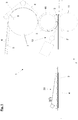
- the Fig. 1 shows the side view of such a workstation 1 in a device according to the invention, which is a workstation for applying bottom cover sheets 3, 3 'on sacks 2, 2' is.
- the transversely conveyed sacks 2, 2 ' lie on a table 4 and are transported by a suitable, not shown transport in the transport direction z.
- the already added floors are also placed in the plane of the table.
- the invention is not limited to this, but the floors can also lie in a plane which is orthogonal to the plane which is spanned by the table level.
- the workstation 1 is supplied with a web material 6, from which the bottom cover sheets 3, 3 'are separated.
- the leading end of the web material 6 is detected by the cutting cylinder 7 and the conveyor belt 8 and pulled forward and cut transversely by the cutting device 7 integrated in the cutting cylinder 7, but not shown in detail.
- the resulting bottom cover sheet 3, 3 ' is taken over by the suction cylinder 10 and placed on the bottom of the bag 2, 2'.
- the suction cylinder 10 forms with the impression cylinder 11 a nip 12. In this way, the bottom cover sheet 3 'is pressed onto the bag 2' with high force.
- FIG. 1 already a part of the bag 2 'has been performed with resting ground cover sheet 3' through the nip.
- the hot air flow 18 is passed into the inlet side of the nip 12.
- the hot air causes a melting of the coating both on the bottom of the Sackes 2 'and on the bottom cover sheet 3'. It will, as the FIG. 1 can be removed, the coatings of the surfaces melted or plasticized, which are brought together immediately thereafter. The bringing together of the surfaces with the still fused coating material takes place in the nip 12, so that the coatings now form an intermediate layer, which can be regarded as homogeneous, between ground cover sheet and ground, which permanently connects said components after cooling.
- the hot air blower is preceded by a preheating 20, which already preheats the next piece of tubing or the next bag 2, so that the material of the bag 2 by the means for generating a hot air stream 13 is no longer supplied as much heat to the plasticization of the surface coating must be, as it would be the case if the bag just before entering the nip 12 still ambient temperature.
- the amount of hot air passed through the nozzle 14 per unit of time can be lower and / or the temperature of the hot air stream can be reduced and / or the residence time of the components to be heated in the hot air stream can be shortened.
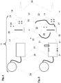
- FIG. 2 shows means for generating a hot air stream 13 according to the prior art, in which a fan 15 generates a continuous flow of air, which is supplied through a pipe 17 of a heater 16. Here the air flow takes up temperature. Subsequently, the resulting hot air stream 18 is supplied to the directional control valve 23. This 23 directs the hot air alternately the exhaust pipe 22 and the nozzle 18 to. The hot air, which flows through the nozzle 14, then contributes in the nip 12 for the temperature-induced joining of the bag components (2, 2 ', 3, 3'). If the directional control valve 23 is set so that it feeds the air to the exhaust pipe 22, an exhaust air flow, which is indicated by the dashed arrow 24.
- FIG. 3 shows means 13 for generating a hot air stream 18, which may be part of a simple embodiment of the invention.
- These means 13 for generating a hot air flow are almost as constructed as the plane described means 13 for generating a hot air flow 18 in FIG. 2 ,
- the flow path 42 is shown as a dashed line. The directional air flow generally follows such a flow path 42 on its way from the place of its production to the point on the sack components 2, 2 ', 3, 3' are joined.
- Heaters 16, 21 for heating the air stream 18 are arranged to this flow path, that they heat the air flow 18. In the case of heating cartridges 21, this may mean that they protrude directly into the airflow 18. It may also mean that heating cartridges 21 or other heating devices 16 heat device elements, which in turn are in direct contact with the air flow.
- the pressure reservoir 27 forms the starting point of the air flow 18, wherein the representation z. B. a suspension of the pressure reservoir 27 has been omitted.
- the weakly heat-conducting tube 17, which may also be made of stainless steel, connects the pressure reservoir 27 with the valve 28, which is associated with a heat sink 39. After passing through the valve 28 of now pulsating air flow passes through the tube 17 in the region of the nozzle plate 34, which is not closed by its cover plate upwards, so that there is a clear view of the channels 36, which are grooves in the Nozzle plate are introduced.
- the nozzle 14 is crossed by channels 36, which fan the air stream 18.
- the nozzle plate is heated, which is indicated by the heating cartridges 21.
- the heating cartridges are advantageously located in holes of the at least one nozzle plate, which is made of a thermally conductive material such as brass or aluminum.
- the channels open to a slot die 37th
- the heated and heated device components in the nozzle region are advantageously insulated from the holder 35, on which the means 13 for generating a hot air stream 18 are suspended, with the insulating material 40.
- the transition of the at least one nozzle plate 34 to the holder can be thermally insulated.
- the cover plates to the outside air may contain insulating material 40.
- the area 38 of attachment of the holder 35 to the machine frame may include further insulating material 40 and / or further insulating material 40 may be placed between the holder and the machine frame.
- the heat sink 39 may be an air-cooled heat sink having cooling fins. Its operative connection to the valve 28 to be cooled can be achieved by mechanical contact, while the operative connection of the cooling device 32 to the valve 28 in FIG. 5 is produced by cooling pipes. In both cases, the valve is intentionally and measurably cooled.
- valve is downstream of the valve in the flow direction x of the air.
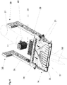
- FIG. 7 is alogiesssizizze of other means 13 for generating a hot air flow, the plurality of pressure reservoirs 27, tubes 17 and valves 28 included.
- the nozzle plate 34 with diverging channels 36 fans the air flow and distributes it to the width of the slot die.
- the heating cartridges are each located near a channel. In this way they can be assigned to one or more channels in their effect. In this way, the heating power can be controlled or regulated over the width of the nozzle and, for example, a temperature gradient (for example, hotter outside than inside) can be impressed.
- the nozzle plate may be interrupted or weakened by slot 41 or it may consist of various components.
Description
- Die Erfindung betrifft ein Verfahren und eine Vorrichtung zum Herstellen von Säcken, deren Wandungen gerecktes Polyolefinmaterial enthalten.
- Es sind Vorrichtungen und Verfahren zur Herstellung von Säcken aus Kunststoff bekannt. Hierbei dienen Schlauchstücke aus Kunststoff oft als Ausgangswerkstücke, welche beispielsweise aus einem beschichteten Kunststoffgewebe bestehen können. Dieses Kunststoffgewebe wird oft aus gereckten Kunststoffbändchen hergestellt, die auf einem Webstuhl zu einem Rundgewebe verwebt werden. Eine andere Möglichkeit ist die Erstellung eines Flachgewebes, welches später durch Zusammenfügen der Längsseiten zu einem Schlauch geformt wird.
- Die Beschichtung des Kunststoffgewebes kann auf zwei Arten erfolgen. So können die gereckten Bändchen vor dem Verweben beschichtet werden. Es bietet sich jedoch an, das fertige Gewebe als Ganzes mit einer einseitigen oder zweiseitigen Beschichtung zu versehen.
- Der Aufbau des Gewebes aus gereckten Kunststoffbändchen und einer Beschichtung verleiht diesem Material besondere Eigenschaften. Die gereckten Kunststoffbändchen sind sehr reißfest und führen bei einem daraus hergestellten Werkstück zu einer hohen Festigkeit, die aufgrund des Verwebens in alle möglichen Lastrichtungen besteht. Um jedoch verschiedene Bestandteile solcher Werkstücke miteinander verbinden zu können, wird die Beschichtung bereitgestellt, welche stark an den Kunststoffbändchen anhaftet. Durch chemische oder thermische Prozesse können diese Beschichtungen, wenn zwei Bestandteile dieser Schlauchstücke oder Säcke verbunden werden sollen, miteinander verschmolzen werden. Der Versuch, die Kunststoffbändchen direkt mit solchen Prozessen zu verbinden, führt häufig zur Beeinträchtigung der Festigkeit. Dies gilt vor allem, wenn Wärme auf die Kunststoffbändchen einwirkt.
- Bei der Herstellung von Säcken aus einem beschichteten Kunststoffgewebe sind Bestandteile, beispielsweise Einschläge bzw. Klappen des späteren Bodens miteinander zu verbinden. Der Herstellungsvorgang läuft folgendermaßen ab: Zunächst wird wenigstens ein Ende eines von einem Schlauch abgetrennten Schlauchstück aufgezogen und ausgestrichen, so dass ein offenes Bodenrechteck und seitliche, dreieckförmige Eckeinschläge entstehen. Anschließend kann ein Ventilzettel oder ein Ventilschlauchstück in den offenen Boden eingelegt werden. Dieses wird in der Regel im Rahmen eines durch Heißluft hervorgerufenen Siegelvorgangs mit dem Boden zusammengefügt. Nun wird der Boden verschlossen, indem die Längskanten des Bodenrechtecks, welche nicht an die Eckeinschläge grenzen, eingefaltet und miteinander sowie im Bedarfsfall mit den Eckeinschlägen und/oder mit dem das Ventil bildende Werkstück verbunden. Schließlich kann noch auf dem Boden, um ihm eine noch höhere Festigkeit zu verleihen, ein so genanntes Bodendeckblatt befestigt werden. Alle vorstehend erwähnten Fügeprozesse, werden nach dem Stand der Technik durch den Eintrag von Heißluft ermöglicht. Die Festlegung der Sackbestandteile gegeneinander erfolgt in der Regel in einem Walzenspalt.
- Die Druckschriften
US 6 134 387 A ,US 4 625 495 A ,EP 1 719 705 A1 ,US 4 210 480 A ,GB 655 893 A SU 1 482 815 A1 - Eine Vorrichtung zur Herstellung von Kreuz- oder Klotzbodensäcken aus dem in Rede stehenden Kunststoffmaterial wird unter anderem von der
DE 195 02 255 C2 gezeigt. Weitere Vorrichtungen zu diesem Zweck sind in den DruckschriftenUS 2002/084028 A1 undEP 0 953 429 A2 offenbart. - Bei den genannten Verfahren, wird ein kontinuierlicher Luftstrom, der in der Regel mit einem Radialverdichter erzeugt wird, an einer Heizvorrichtung vorbeigeführt, wobei sich die Luft erwärmt. Der nun erhitzte Luftstrom wird durch ein Wegeventil - das als temperaturbeständiges Drehventil ausgeführt ist - geführt, das den Luftstrom an eine Breitschlitzdüse weiterleitet, wenn sich ein Sack in der Fügestation befindet. Wenn sich kein Sack in der Fügestation befindet, befindet sich das Wegeventil in einem anderen Schaltzustand und leitet die Luft in einen Abluftschlauch, der die Luft ableitet.
- Es gehört zu den ständigen Bestrebungen der Fachwelt, die Produktionsgeschwindigkeit von Sackmaschinen zu erhöhen. Um auch beim temperaturinduzierten Fügen von Sackbestandteilen eine höhere Geschwindigkeit erreichen zu können, schlägt die
DE 101 04 002 B4 vor, Zettel - also vor allem Ventilzettel oder Bodendeckblätter - bereits vor dem eigentlichen Fügeprozess, bei dem die Zettel unter Druck und zusätzlichem Temperatureintrag auf die Sackböden aufgebracht werden, aufzuwärmen. - Die
EP 2 125 353 B1 schlägt in ähnlichem Zusammenhang vor, die Sackböden, die oft mit den genannten Zetteln beaufschlagt werden, mit Heißluft vorzuwärmen. - Die genannten Maßnahmen tragen durchaus zu einer Beschleunigung der Sackproduktion bei. Der Bedarf nach noch schnelleren Produktionsvorrichtungen und -verfahren besteht jedoch noch immer.
- Daher besteht die Aufgabe der vorliegenden Erfindung darin, einen weiteren Beitrag zur Beschleunigung der Produktion von Säcken, deren Wandungen gerecktes Polyolefinmaterial enthalten, zu leisten.
- Diese Aufgabe wird durch die Ansprüche 1 und 6 gelöst.
- Die vorliegende Erfindung macht sich zu Nutze, dass der pulsierende Luftstrom nur dann maximale Mengen thermischer Energie aufnimmt, wenn sie zum Fügen gebraucht wird. Daher kommt es nicht zu einer unnötigen Abkühlung von Heizelementen während der Intervalle, in denen keine Säcke in der Fügestation sind.
- Ein pulsierender Luftstrom ist ein Luftstrom mit wechselnder Strömungsgeschwindigkeit. Oft stellen sich regelmäßige Wechsel derselben ein, die eine sinusähnliche Abhängigkeit von der Zeit mit sich bringen, wobei die Luftströmungen nicht völlig zum Erliegen kommen müssen.
- Zu den weiteren Vorteilen der Erfindung gehört, dass in der Regel keine aufwändigen relativ temperaturunanfälügen Wegeventile (Drehventile) zur Durchführung des Verfahrens notwendig sind. Diese Drehventile sind teuer, oft undicht und sie haben eine große Wärmekapazität. Insbesondere, wenn diese Ventile nicht im Rahmen der Umsetzung der vorliegenden Erfindung verwendet werden und unter anderem der gesamte Luftstrom unterbrochen wird, wenn sich kein Sack in der Fügestation befindet, lassen sich mit der Erfindung auch große Energieeinsparungen erzielen.
- Luftströmungen können durch Druckgradienten zustande kommen. Erfindungsgemäß wird ein pulsierender Luftstrom mit einem Druckreservoir und einem ventilartigen Schaltelement hergestellt. Ein Spezialfall eines pulsierenden Luftstromes ist ein Luftstrom, der zeitweise völlig unterbrochen wird, was bei der vorgenannten Art der Erzeugung des betreffenden Luftstromes heißen kann, dass das Ventil ganz verschlossen wird. Ein temperaturinduzierter Fügeprozess ist ein Verbindungsprozess, der unter Temperatureintrag stattfindet. Auch Klebeprozesse, die auf diese Art stattfinden, sind denkbar. In der Regel enthalten Sackwandungen, die gerecktes Polyolefinmaterial enthalten, auch eine weitere Kunststoff- oder Polyolefinkomponente, die eine niedrigere Schmelz- und/oder Erweichungstemperatur besitzt als das gereckte Material. Typisch sind in diesem Zusammenhang Gewebe aus gereckten Polypropylenbändchen, die mit niedriger schmelzendem Polyolefin laminiert oder sonst irgendwie beschichtet sind.
- Der Temperatureintrag mit Heißluft erhitzt das niedriger schmelzende Material bis es sich siegeln oder schweißen lässt. Vorteilhaft ist, wenn das gereckte Material zu diesem Zeitpunkt noch nicht die Temperatur erreicht hat, bei der es seine im Reckprozess erworbenen Eigenschaften verliert oder zu verlieren beginnt.
- Ein Druckreservoir im Sinne der vorliegenden Anmeldung liegt vor, wenn ein Raum einen höheren Druck aufweist als seine Umgebung. Ein solches Druckreservoir kann eine Pressluftflasche sein, es kann aber auch ein Raum sein, in den ein geeignetes Gebläse Luft hineinpresst und dabei verdichtet. Hierbei kann das Gebläse auch in geregelter Form betrieben werden, wobei der zu erreichende Sollwert ein bestimmter Druckwert sein kann. Das Gebläse beziehungsweise der Verdichter kann während mehrerer Fügeprozesse kontinuierlich arbeiten.
- Zur kontinuierlichen Bereitstellung von Luft höheren Drucks gibt es eine Vielzahl vorteilhafter Möglichkeiten. Aufgrund des hohen Bedarfs an Luft bei dem Sackproduktionsprozess ist es vorteilhaft, wenn ein geeigneter Kompressor oder Verdichter in einer Arbeitsposition zu dem zumindest einen Druckreservoir steht. Die Arbeitsposition kann darin bestehen, dass ein Kompressor einem oder mehreren Druckreservoiren zugeordnet - also über Leitungen mit ihnen verbunden - ist. Kompressoren oder Verdichter können jedoch auch ein Druckluftsystem speisen, dass Druckluft für unterschiedliche Bestandteile der Sackfabrik bereitstellt.
- Eine vorteilhafte Möglichkeit, die verdichtete Luft bereitzustellen, sind im vorliegenden Zusammenhang Turboverdichter.
- Der Begriff Luft wird im Zusammenhang mit der vorliegenden Druckschrift als Synonym für gasförmige Medien verwendet. Natürlich können statt Luft auch geeignete Gase wie Stickstoff verwendet werden. Dies gilt insbesondere, wenn bei der Erhitzung des Sackmaterials Oxidationen zu befürchten sind.
- Die Luft kann vorteilhafterweise durch eine Mehrzahl von Kanälen geführt werden. Diese Kanäle können dem Ventil nachgelagert sein und sie können der Erhitzung der Luft dienen. In diesem Zusammenhang ist es vorteilhaft, wenn die Kanäle aus einem Metall, vorzugsweise aus Aluminium, Kupfer oder Messing hergestellt sind. Eine vorteilhafte Möglichkeit besteht in der Bereitstellung einer "Kanalplatte oder Düsenplatte", die mit Nuten oder Bohrungen, die die Kanäle bilden, versehen ist. Diese Platte kann durch zumindest eine Heizvorrichtung, wie ein Thermoelement, geheizt werden. Als Thermoelement wird dürfte oft eine Heizpatrone oder auch ein Pelletierelement Verwendung finden.
- Es ist vorteilhaft, wenn die Kanäle den Luftstrom auffächern, also beispielsweise aus einem schmalen Luftstrom einen breiten Luftstrom machen. Auch ein Vorwärmen der zu fügenden Sackbestandteile ist vorteilhaft. Auch hierbei kann ein pulsierender Luftstrom im Sinne der in dieser Druckschrift vorgestellten Vorrichtungen und Verfahren vorteilhaft zum Einsatz kommen. Es ist von großem Vorteil, wenn zumindest ein Druckreservoir in der oben besprochenen Weise eingesetzt wird. Dieses zumindest eine Druckreservoir kann beheizt werden. Hierbei ist die allgemeine Gasgleichung zu beachten. So ist es vorteilhaft, die Heizung nach der Temperatur zu regeln, den Druck in dem Reservoir zu regeln und/oder zumindest ein Überdruckventil vorzusehen.
- Weitere Ausführungsbeispiele der Erfindung gehen aus der nun folgenden gegenständlichen Beschreibung und der Zeichnung hervor.
- Die einzelnen Figuren zeigen:
- Fig. 1
- Seitenansicht einer Arbeitsstation in einer Vorrichtung zur Herstellung von Säcken, deren Bestandteile gerecktes Polyolefin-Material enthalten.
- Fig. 2
- Eine (seitliche) Funktionsskizze von Mitteln zum Erzeugen eines Heißluftstroms gemäß dem Stand dem Technik
- Fig. 3
- Eine (seitliche) Funktionsskizze von erfindungsgemäßen Mitteln zum Erzeugen eines Heißluftstroms
- Fig. 4
- Eine (seitliche) Funktionsskizze von weiteren erfindungsgemäßen Mitteln zum Erzeugen eines Heißluftstroms
- Fig. 5
- Eine (seitliche) Funktionsskizze von weiteren erfindungsgemäßen Mitteln zum Erzeugen eines Heißluftstroms
- Fig. 6
- Eine Funktionsskizze (als Draufsicht) von weiteren erfindungsgemäßen Mitteln zum Erzeugen eines Heißluftstroms
- Fig. 7
- Eine Funktionsskizze (als Draufsicht) von weiteren erfindungsgemäßen Mitteln zum Erzeugen eines Heißluftstroms
- Wie bereits in der einleitenden Beschreibung ausführlich dargelegt wurde, sind bei der Herstellung von Säcken aus beschichteten Kunststoffgewebeschläuchen mehrere Verfahrensschritte notwendig. Insbesondere zum Verbinden verschiedener Bestandteile der späteren Säcke sind entsprechende Arbeitsstationen vorzusehen. Im Einzelnen sind dies: eine Arbeitsstation zum Aufbringen von Ventilzetteln, Arbeitsstationen zum dauerhaften Verschließen der Böden und Arbeitsstationen zum Aufbringen von Bodendeckblättern, die die Böden der Säcke verstärken. Auf den Einsatz von Arbeitsstationen zum Aufbringen der Bodendeckblätter kann gegebenenfalls verzichtet werden. Weitere Arbeitsstationen sind denkbar.
- In der Regel sind die Arbeitsstationen doppelt ausgeführt, so dass die entsprechenden Arbeiten gleichzeitig an beiden Enden der Schlauchstücke, welche in der Regel quer zu ihrer Schlauchlängsachse gefördert werden, ausgeführt werden können. Die Anzahl der Arbeitsstationen zum Einbringen der Ventilblätter oder -schläuche kann von dieser Regel, je nach gewünschter Anzahl der Ventile, abweichen.
- Die
Fig. 1 zeigt die Seitenansicht auf eine solche Arbeitsstation 1 in einer erfindungsgemäßen Vorrichtung, bei der es sich um eine Arbeitsstation zum Aufbringen von Bodendeckblättern 3, 3' auf Säcke 2, 2' handelt. Die quer geförderten Säcke 2, 2' liegen dabei auf einem Tisch 4 auf und werden durch ein geeignetes, nicht gezeigtes Transportmittel in Transportrichtung z transportiert. Die bereits zugelegten Böden sind ebenfalls in die Ebene des Tisches gelegt. Die Erfindung ist hierauf jedoch nicht beschränkt, vielmehr können die Böden auch in einer Ebene liegen, die orthogonal zu der Ebene verläuft, die durch die Tischebene aufgespannt wird. - Über einen Zulauf 5 wird der Arbeitstation 1 ein Bahnmaterial 6 zugeführt, von dem die Bodendeckblätter 3, 3' abgetrennt werden. Dazu wird das voraus laufende Ende des Bahnmaterials 6 vom Schneidzylinder 7 und dem Transportband 8 erfasst und vorgezogen und von der im Schneidzylinder 7 integrierten, aber nicht näher gezeigten Schneideinrichtung 9 quer geschnitten. Das so entstandene Bodendeckblatt 3, 3' wird vom Saugzylinder 10 übernommen und auf den Boden des Sackes 2, 2' gelegt. Der Saugzylinder 10 bildet mit dem Gegendruckzylinder 11 einen Walzenspalt 12. Auf diese Weise wird das Bodendeckblatt 3' auf den Sack 2' mit hoher Kraft aufgepresst. In der
Figur 1 ist bereits ein Teil des Sackes 2' mit aufliegendem Bodendeckblatt 3' durch den Walzenspalt geführt worden. Einlaufseitig des Walzenspaltes 12 sind Mittel zum Erzeugen eines Heißluftstromes 13 angeordnet, deren Heißluftstrom 18 in die Einlaufseite des Walzenspaltes 12 geleitet wird. Die Heißluft verursacht ein Anschmelzen der Beschichtung sowohl auf dem Boden des Sackes 2' als auch auf dem Bodendeckblatt 3'. Dabei werden, wie es derFigur 1 entnehmbar ist, die Beschichtungen der Oberflächen angeschmolzen bzw. plastifiziert, die unmittelbar danach zusammengebracht werden. Das Zusammenbringen der Oberflächen mit dem noch angeschmolzenen Beschichtungsmaterial erfolgt in dem Walzenspalt 12, so dass die Beschichtungen nunmehr eine Zwischenschicht, die als homogen angesehen werden kann, zwischen Bodendeckblatt und Boden bilden, welche die genannten Bestandteile nach dem Auskühlen dauerhaft verbindet. - In Transportrichtung z ist dem Heißluftgebläse eine Vorwärmeinrichtung 20 vorgelagert, welche bereits das nächste Schlauchstück bzw. den nächsten Sack 2 vorwärmt, so dass dem Material des Sacks 2 durch die Mittel zum Erzeugen eines Heißluftstromes 13 nicht mehr so viel Wärme bis zur Plastifizierung der Oberflächenbeschichtung zugeführt werden muss, wie es der Fall wäre, wenn der Sack kurz vor dem Einlauf in den Walzenspalt 12 noch Umgebungstemperatur hätte. Auf diese Weise kann die durch die Düse 14 pro Zeiteinheit hindurchgeleitete Heißluftmenge geringer ausfallen und/oder die Temperatur des Heißluftstromes reduziert werden und/oder die Verweilzeit der zu erhitzenden Bestandteile im Heißluftstrom verkürzt werden. Der Aufbau und die Funktion der Mittel zum Erzeugen eines Heißluftstromes werden nachstehend aufgrund der
Figuren 2 bis 7 erklärt.
Figur 2 zeigt Mittel zum Erzeugen eines Heißluftstromes 13 nach dem Stand der Technik, bei denen ein Gebläse 15 einen kontinuierlichen Luftstrom erzeugt, der durch ein Rohr 17 einer Heizvorrichtung 16 zugeführt wird. Hier nimmt der Luftstrom Temperatur auf. Anschließend wird der entstandene Heißluftstrom 18 dem Wegeventil 23 zugeführt. Dieses 23 leitet die Heißluft abwechselnd dem Abluftrohr 22 und der Düse 18 zu. Die Heißluft, die die Düse 14 durchströmt, trägt anschließend im Walzenspalt 12 zum temperaturinduzierten Fügen der Sackbestandteile (2, 2', 3, 3') bei. Wenn das Wegeventil 23 so eingestellt ist, dass es die Luft dem Abluftrohr 22 zuleitet, entsteht ein Abluftstrom, der durch den gestrichelten Pfeil 24 angedeutet ist.
Figur 3 zeigt Mittel 13 zum Erzeugen eines Heißluftstroms 18, die Bestandteil einer einfachen Ausführungsform der Erfindung sein können. Diese Mittel 13 zum Erzeugen eines Heißluftstroms sind fast so aufgebaut wie die eben beschriebenen Mittel 13 zum Erzeugen eines Heißluftstroms 18 inFigur 2 . Es unterschieden sich lediglich die Heizpatronen 21, die im Bereich des dem Ventil 23 nachgelagerten Rohres 17 und der ebenfalls dem Ventil 23 nachgelagerten Düse 14 angebracht sind. Sie stehen in einer thermischen Wirkverbindung zu dem Heißluftstrom 18, der nach dem Ventil 23 eben ein pulsierender Heißluftstrom ist.
In denFiguren 2 und 3 ist der Strömungspfad 42 als gestrichelte Linie eingezeichnet. Die gerichtete Luftströmung folgt in aller Regel einem solchen Strömungspfad 42 auf ihrem Weg von dem Ort ihrer Erzeugung bis zu der Stelle an der Sackbestandteile 2, 2', 3, 3' gefügt werden. Heizvorrichtungen 16, 21 zur Erhitzung des Luftstromes 18 sind derart zu diesem Strömungspfad angeordnet, dass sie den Luftstrom 18 erhitzen. Bei Heizpatronen 21 kann das heißen, dass diese direkt in den Luftstrom 18 hineinragen. Es kann aber auch heißen, dass Heizpatronen 21 oder andere Heizvorrichtungen 16 Vorrichtungselemente, welche ihrerseits in direktem Kontakt mit dem Luftstrom stehen, heizen. - In
Figur 4 ist ein Verdichter vorgesehen, der ein gasförmiges Medium, vorzugsweise Luft, durch den Druckschlauch 26 in das Druckreservoir 27 presst. Durch das Rohr 17 gelangt die Luft zu dem Ventil 28, das nach einem anderen Funktionsprinzip als das Dreh- oder Wegeventil 23 funktionieren kann, was durch den Schieber 30 und den Doppelpfeil 29 angedeutet ist. In diesem Zusammenhang können durchaus elektronische Ventile, die sehr schnell schalten können, zum Einsatz kommen. Dem Ventil sind ein weiteres Rohr 17, die Düse 14 und die Heizpatronen 21 in der Strömungsrichtung x der Heißluft nachgelagert. Die Heizpatronen 21 fungieren somit als Heizvorrichtung für den aufgrund des Einsatzes des Ventils 28 pulsierenden Heißluftstrom 18.
Die inFigur 5 gezeigten Mittel 13 zum Erzeugen eines Heißluftstromes 18 unterscheiden sich durch die Mittel 13 ausFigur 4 durch die folgenden Merkmale: - Bereits das Druckreservoir 27 ist durch die Heizpatronen 21 beheizbar. Alternativ und ergänzend kommt in Frage, das Druckreservoir 27 gut thermisch zu isolieren, da die Verdichtung der Luft durch den Verdichter 25 zu einer Steigerung der Temperatur führt. Temperatur, Druck des Druckreservoirs 21 sowie Heizleistung der Heizpatronen können alternativ oder ergänzend gemessen oder gar geregelt werden. Eine weitere vorteilhafte Maßnahme besteht in der Anbringung eines Überdruckventils 31, das bei einer Überschreitung eines Maximaldrucks Luft ablässt. Da nun das Druckreservoir 27 heiß sein kann, und ein temperaturempfindliches Ventil zum Einsatz kommen kann, ist es vorteilhaft, das Rohr 17 möglichst dünnwandig (aber druckbeständig genug) und aus isolierendem Material (z. B. Keramik) herzustellen. Das Ventil 28 ist kühlbar. Dies wird durch die Kühlvorrichtung 32 und die Kühlleitungen 33 angedeutet. Es kann sich um eine Wasserkühlung handeln, aber auch Kühlelemente, wie Pelletierelemente sind vorteilhaft. Auch das dem Ventil in Luftströmungsrichtung x nachgelagerte Rohr kann dünnwandig und isolierend sein. Im Bereich der Düse, die ja wieder von dem pulsierenden Luftstrom 18 durchströmt wird, der aktiviert wird soweit sich zu fügendes Material in der Fügestation 1 beziehungsweise im Bereich des Walzenspalts 12 befindet, befinden sich wieder Heizpatronen zum Heizen der Luft.
- Mit den in den
Figuren 4 und 5 gezeigten Vorrichtungen wird kein pulsierender Abluftstrom erzeugt. Dies gilt auch für die inFigur 6 gezeigte Vorrichtung, die den beiden vorgenannten Vorrichtungen stark ähnelt. Das Druckreservoir 27 bildet den Ausgangspunkt des Luftstromes 18, wobei auf die Darstellung z. B. einer Aufhängung des Druckreservoirs 27 verzichtet wurde. Das schwach Wärme leitende Rohr 17, das auch aus Edelstahl sein kann, verbindet das Druckreservoir 27 mit dem Ventil 28, dem ein Kühlkörper 39 zugeordnet ist. Nach dem Durchtritt durch das Ventil 28 gelangt der nunmehr pulsierende Luftstrom durch das Rohr 17 in den Bereich der Düsenplatte 34, die nicht von ihrer Abdeckplatte nach oben verschlossen ist, so dass sich ein freier Blick auf die Kanäle 36 ergibt, die als Nuten in die Düsenplatte eingebracht sind. Auf diese Weise wird die Düse 14 von Kanälen 36 durchzogen, die den Luftstrom 18 auffächern. Die Düsenplatte ist beheizbar, was durch die Heizpatronen 21 angedeutet ist. Die Heizpatronen sitzen vorteilhafterweise in Bohrungen der zumindest einen Düsenplatte, die aus einem wärmeleitfähigen Material wie Messing oder Aluminium angefertigt ist. Am Ende der Düsenplatte öffnen sich die Kanäle zu einer Breitschlitzdüse 37. - Die beheizten und erhitzen Vorrichtungsbestandteile im Düsenbereich sind vorteilhafterweise gegen den Halter 35, an dem die Mittel 13 zur Erzeugung eines Heißluftstromes 18 aufgehängt sind, mit dem Isoliermaterial 40 isoliert. So kann der Übergang der zumindest einen Düsenplatte 34 zu dem Halter wärmeisoliert werden. Auch die Abdeckplatten zur Außenluft können Isoliermaterial 40 enthalten.
- Es ist denkbar, Teile des Halters aus temperaturbeständigem Kunststoff zu fertigen.
- Des Weiteren kann der Bereich 38 der Befestigung des Halters 35 am Maschinengestell weiteres Isoliermaterial 40 enthalten und/oder es kann weiteres Isoliermaterial 40 zwischen den Halter und das Maschinengestell gebracht werden.
- Der Kühlkörper 39 kann ein von Luft durchströmter Kühlkörper sein, der Kühlrippen besitzt. Seine Wirkverbindung zu dem zu kühlenden Ventil 28 kann durch mechanischen Kontakt zustande kommen, während die Wirkverbindung der Kühlvorrichtung 32 zu dem Ventil 28 in
Figur 5 durch Kühlleitungen hergestellt wird. In beiden Fällen wird das Ventil, gewollt, gezielt und messbar gekühlt. - In
Figur 6 ist das Ventil in der Strömungsrichtung x der Luft dem Ventil nachgelagert. -
Figur 7 ist eine Funktionsskizze von weiteren Mitteln 13 zum Erzeugen eines Heißluftstromes, die mehrere Druckreservoire 27, Rohre 17 und Ventile 28 enthalten. Wieder fächert die Düsenplatte 34 mit auseinander laufenden Kanälen 36 die Luftströmung auf und verteilt sie auf die Breite der Breitschlitzdüse. Die Heizpatronen sind jeweils in der Nähe eines Kanals angeordnet. Auf diese Weise lassen sie sich in ihrer Wirkung einem oder mehreren Kanälen zuordnen. Auf diese Weise kann die Heizleistung über die Breite der Düse gesteuert oder geregelt werden und es kann beispielsweise ein Temperaturgradient (z. B. außen heißer als innen) aufgeprägt werden. Um die Zuordnung einzelner Heizvorrichtungen zu einzelnen oder mehreren Kanälen zu verbessern, kann die Düsenplatte durch Schlitz 41 unterbrochen oder geschwächt werden oder sie kann aus verschiedenen Bauteilen bestehen.Bezugszeichenliste 1 Arbeitsstation 2, 2' Sack 3, 3' Bodendeckblatt 4 Tisch 5 Zulauf 6 Bahnmaterial 7 Schneidzylinder 8 Transportband 9 Schneideinrichtung 10 Saugzylinder 11 Gegendruckzylinder 12 Walzenspalt 13 Mittel zum Erzeugen eines Heißluftstromes 14 Düse 15 Gebläse 16 Heizvorrichtung 17 Rohr 18 Heißluftstrom 19 Drehventil 20 Vorwärmeinrichtung 21 Heizpatronen 22 Abluftrohr 23 Drehventil 24 Abluftstrom 25 Verdichter/Kompressor 26 Druckschlauch 27 Druckreservoir 28 Ventil 29 Doppelpfeil 30 Ventilschieber 31 Überdruckventil 32 Kühlvorrichtung 33 Kühlleitung 34 Düsenplatte 35 Halter 36 Kanäle 37 Breitschlitzdüse 38 Befestigungsbereich des Halters 35 39 Kühlkörper 40 Isoliermaterial 41 Schlitz in der Düsenplatte 42 Strömungspfad x Strömungsrichtung der Heißluft z Transportrichtung der Säcke 2, 2'
Claims (12)
- Verfahren zum Herstellen von Säcken (2,2'), deren Wandungen Gewebe aus gerecktem Polyolefinmaterial und Beschichtungen enthalten,- bei welchem zumindest ein temperaturinduzierter Fügeprozess herbeigeführt wird, indem zumindest ein Teil des zu fügenden Materials (2, 2', 3, 3') mit einem Heißluftstrom (18) erhitzt wird,- der (18) erzeugt wird, indem zunächst Luft an einer oder mehreren Heizvorrichtungen (16, 21) vorbeigeführt wird und dann auf das zu fügende Material (2, 2', 3, 3') geleitet wird,- wobei der Heißluftstrom in die Einlaufseite eines Walzenspalts (12) geleitet wird und wobei die Beschichtungen der Oberflächen des zu fügenden Materials angeschmolzen und in dem Walzenspalt zusammengebracht werden,dadurch gekennzeichnet, dass
der Luftstrom (18) pulsierend an zumindest einer Heizvorrichtung (16, 21) vorbeigeführt wird, wobei zumindest ein Ventil (23, 28) betätigt wird, um den pulsierenden Luftstrom (18) zu erzeugen und mit dem Ventil (23, 28) die Öffnung eines Druckreservoirs (27) gesteuert wird, das einen höheren Druck als den Atmosphärendruck aufweist. - Verfahren nach dem vorstehenden Anspruch,
dadurch gekennzeichnet, dass
der Luftstrom (18) zwischen zwei Pulsen unterbrochen wird. - Verfahren nach einem der vorstehenden Ansprüche,
dadurch gekennzeichnet, dass
das Druckreservoir (27) während einer Mehrzahl von Fügeprozessen aufgeladen wird. - Verfahren nach einem der vorstehenden Ansprüche,
dadurch gekennzeichnet, dass
die Luft, die dem Boden eines Sackes (2, 2') zugeführt wird, durch mehrere Kanäle (36) geleitet wird. - Verfahren nach einem der vorstehenden Ansprüche,
dadurch gekennzeichnet, dass
zumindest ein Teil des zu fügenden Materials (2, 2', 3, 3') vorgewärmt wird, bevor es mit dem pulsierenden Luftstrom (18) und unter Krafteinwirkung gefügt wird. - Vorrichtung zur Herstellung von Säcken (2, 2') aus Sackmaterial, das Gewebe aus gerecktem Polyolefinmaterial und eine Beschichtung enthält,- welche zumindest eine Station (1) zum temperaturinduzierten Fügen des Sackmaterials (2, 2', 3, 3') enthält,- wobei diese Station (1) einen Walzenspalt (12) und Mittel (13) zum Erzeugen eines Luftstromes (18) enthält, welche zum Extrudieren eines gerichteten Luftstromes (18) geeignet sind,- wobei diese Mittel (13) eine oder mehrere Heizvorrichtungen (16, 21) enthalten, die derart zu dem Luftstrom (18) angeordnet sind, dass der Luftstrom (18) erhitzt wird,- wobei der Heißluftstrom durch die Mittel (13) zum Erzeugen eines Luftstroms in die Einlaufseite des Walzenspalts (13) leitbar ist und- wobei mit dem Heißluftstrom die Beschichtungen der Oberflächen des Sackmaterials anschmelzbar sind und in dem Walzenspalt (12) zusammen bringbar sind,dadurch gekennzeichnet,
dass zumindest ein Ventil (23, 28) in der Richtung des Luftstromes (x) zumindest einer Heizvorrichtung (16, 21) vorgelagert ist, wobei der Heißluftstrom aufgrund des Einsatzes des Ventils (23, 28) pulsierbar ist, und
dass dem Ventil (23, 28) in der Richtung (x) des Luftstromes (18) zumindest ein Druckreservoir (27) vorgelagert ist. - Vorrichtung nach dem vorstehenden Anspruch,
dadurch gekennzeichnet, dass
das zumindest eine Druckreservoir (27) beheizbar ist. - Vorrichtung nach einem der beiden vorstehenden Ansprüche,
dadurch gekennzeichnet, dass
das zumindest eine Druckreservoir (27) zur Speicherung von Pressluft geeignet ist. - Vorrichtung nach einem der vorstehenden Ansprüche 6 bis 8, dadurch gekennzeichnet, dass
dem zumindest einen Ventil (23, 28) in der Strömungsrichtung (x) zumindest zwei Luftkanäle (36) zum Führen des Luftstroms (18) entlang des Strömungspfades nachgelagert sind. - Vorrichtung nach dem vorstehenden Anspruch,
dadurch gekennzeichnet, dass
dass zumindest einer der zumindest zwei Luftkanäle (36) beheizbar ist. - Vorrichtung nach einem der beiden vorstehenden Ansprüche,
dadurch gekennzeichnet, dass
zumindest einer der beiden Kanäle (36) sich in der Strömungsrichtung (x) verbreitert. - Vorrichtung nach einem der vorstehenden Ansprüche 6 bis 11 gekennzeichnet durch
eine Kühlvorrichtung (32, 39), die in Wirkverbindung mit dem zumindest einen Ventil (23, 28) steht.
Applications Claiming Priority (2)
| Application Number | Priority Date | Filing Date | Title |
|---|---|---|---|
| DE102011005109A DE102011005109A1 (de) | 2011-03-04 | 2011-03-04 | Verfahren und Vorrichtung zum Herstellen von Säcken, deren Wandungen gerecktes Polyolefinmaterial enthalten |
| PCT/EP2012/053121 WO2012119863A1 (de) | 2011-03-04 | 2012-02-24 | Verfahren und vorrichtung zum herstellen von säcken, deren wandungen gerecktes polyolefinmaterial enthalten |
Publications (2)
| Publication Number | Publication Date |
|---|---|
| EP2681033A1 EP2681033A1 (de) | 2014-01-08 |
| EP2681033B1 true EP2681033B1 (de) | 2017-09-06 |
Family
ID=45815512
Family Applications (1)
| Application Number | Title | Priority Date | Filing Date |
|---|---|---|---|
| EP12708274.1A Active EP2681033B1 (de) | 2011-03-04 | 2012-02-24 | Verfahren und vorrichtung zum herstellen von säcken, deren wandungen gerecktes polyolefinmaterial enthalten |
Country Status (7)
| Country | Link |
|---|---|
| EP (1) | EP2681033B1 (de) |
| JP (1) | JP6089303B2 (de) |
| CN (1) | CN103534080A (de) |
| BR (1) | BR112013022660A2 (de) |
| DE (1) | DE102011005109A1 (de) |
| HU (1) | HUE035601T2 (de) |
| WO (1) | WO2012119863A1 (de) |
Families Citing this family (6)
| Publication number | Priority date | Publication date | Assignee | Title |
|---|---|---|---|---|
| JP4230080B2 (ja) * | 2000-02-18 | 2009-02-25 | リンテック株式会社 | ウエハ貼着用粘着シート |
| DE102014214593A1 (de) * | 2014-07-24 | 2016-01-28 | Windmöller & Hölscher Kg | Heißluftsiegeleinrichtung und Verfahren zum Heißluftsiegeln von kunststoffhaltiger Verpackung |
| WO2018073285A1 (de) * | 2016-10-18 | 2018-04-26 | Windmöller & Hölscher Kg | Vorrichtung und verfahren zur herstellung von säcken aus kunststoffmaterial |
| ES2857910T3 (es) * | 2018-12-17 | 2021-09-29 | Starlinger & Co Gmbh | Dispositivo y procedimiento para aplicar hojas de recubrimiento sobre extremos preformados para dar fondos cruzados de secciones de manguera |
| CN109808237A (zh) * | 2019-03-22 | 2019-05-28 | 中山市新宏业自动化工业有限公司 | 一种软包装袋在线加导流条装置 |
| CN111841664A (zh) * | 2020-08-05 | 2020-10-30 | 巨轮智能装备股份有限公司 | 一种离子交换膜制造用塑料膜片连续速热封接方法 |
Citations (1)
| Publication number | Priority date | Publication date | Assignee | Title |
|---|---|---|---|---|
| DE10104002A1 (de) * | 2000-12-12 | 2002-07-18 | Windmoeller & Hoelscher | Verfahren zum Temperieren zu verklebender Kunststofffolien sowie Vorrichtung zum Verkleben von Kunstfolie mit temperaturgesteuerter Transportwalze |
Family Cites Families (12)
| Publication number | Priority date | Publication date | Assignee | Title |
|---|---|---|---|---|
| GB655893A (en) * | 1948-05-25 | 1951-08-08 | Robinson E S & A Ltd | Improvements in or relating to the manufacture of paper and like bags |
| US3481051A (en) * | 1969-02-06 | 1969-12-02 | Paramount Packaging Corp | Heating apparatus |
| US4210480A (en) * | 1978-08-17 | 1980-07-01 | St. Regis Paper Company | Steam seal of bag ply |
| US4625495A (en) * | 1985-08-16 | 1986-12-02 | Mobil Oil Corporation | Method of packaging and system therefor |
| SU1482815A1 (ru) * | 1987-09-28 | 1989-05-30 | Могилевский Машиностроительный Институт | Горелка дл сварки термопластичных материалов |
| DE19502255C2 (de) | 1995-01-25 | 1996-11-28 | Windmoeller & Hoelscher | Vorrichtung zum Aufbringen von Zetteln aus Kunststoffolie auf flachliegende Werkstücke |
| DE19542488A1 (de) * | 1995-05-15 | 1997-05-22 | Hainsberger Metallwerk Gmbh | Verfahren und Vorrichtung zum Heißgasschweißen von Kunststoffolien |
| DE19818720B4 (de) * | 1998-04-27 | 2008-08-07 | Windmöller & Hölscher Kg | Verfahren zum Verschweißen von kontinuierlich geförderten Kunststoffolien |
| ATA17172001A (de) * | 2000-12-12 | 2005-05-15 | Windmoeller & Hoelscher | Verfahren zum temperieren zu verklebender kunststofffolien sowie vorrichtung zum verkleben von kunststofffolie mit temperaturgesteuerter transportwalze |
| ES2287832T3 (es) * | 2005-04-19 | 2007-12-16 | TEEPACK SPEZIALMASCHINEN GMBH & CO. KG | Maquiana para formar, llenar y cerrar bolsas tubulares. |
| DE102007004244B4 (de) | 2007-01-23 | 2010-09-02 | Windmöller & Hölscher Kg | Vorrichtung und Verfahren zur Herstellung von Kunststoffsäcken |
| DE102009056078B8 (de) | 2009-11-30 | 2012-06-14 | Windmöller & Hölscher Kg | Verfahren und Vorrichtung zur Herstellung von Pinchsäcken sowie Station zur Bildung von Pinchböden |
-
2011
- 2011-03-04 DE DE102011005109A patent/DE102011005109A1/de not_active Withdrawn
-
2012
- 2012-02-24 HU HUE12708274A patent/HUE035601T2/en unknown
- 2012-02-24 BR BR112013022660A patent/BR112013022660A2/pt not_active IP Right Cessation
- 2012-02-24 EP EP12708274.1A patent/EP2681033B1/de active Active
- 2012-02-24 WO PCT/EP2012/053121 patent/WO2012119863A1/de active Application Filing
- 2012-02-24 JP JP2013555827A patent/JP6089303B2/ja not_active Expired - Fee Related
- 2012-02-24 CN CN201280011700.XA patent/CN103534080A/zh active Pending
Patent Citations (1)
| Publication number | Priority date | Publication date | Assignee | Title |
|---|---|---|---|---|
| DE10104002A1 (de) * | 2000-12-12 | 2002-07-18 | Windmoeller & Hoelscher | Verfahren zum Temperieren zu verklebender Kunststofffolien sowie Vorrichtung zum Verkleben von Kunstfolie mit temperaturgesteuerter Transportwalze |
Also Published As
| Publication number | Publication date |
|---|---|
| JP6089303B2 (ja) | 2017-03-08 |
| HUE035601T2 (en) | 2018-05-28 |
| JP2014510654A (ja) | 2014-05-01 |
| BR112013022660A2 (pt) | 2016-12-06 |
| DE102011005109A1 (de) | 2012-09-06 |
| WO2012119863A1 (de) | 2012-09-13 |
| EP2681033A1 (de) | 2014-01-08 |
| CN103534080A (zh) | 2014-01-22 |
Similar Documents
| Publication | Publication Date | Title |
|---|---|---|
| EP2681033B1 (de) | Verfahren und vorrichtung zum herstellen von säcken, deren wandungen gerecktes polyolefinmaterial enthalten | |
| EP1976680B1 (de) | Vorrichtung und verfahren zum herstellen eines dreidimensionalen objektes mittels eines beschichters für pulverförmiges aufbaumaterial | |
| EP2433769B1 (de) | Vorrichtung und Verfahren zum Beschichten eines Werkstücks | |
| EP2832509B1 (de) | Aktivierungsmodul für eine Beschichtungsvorrichtung mit einer Beschichtungsvorrichtung | |
| DE102008062199A1 (de) | Verfahren und Heizeinrichtung zum Thermoformen | |
| EP2125353B1 (de) | Vorrichtung und verfahren zur herstellung von kunststoffsäcken | |
| DE1289297B (de) | Verfahren und Vorrichtung zur kontinuierlichen Herstellung mehrschichtiger Schlaeuche aus thermoplastischen Kunststoffen nach dem Extrusionsverfahren | |
| EP2773914B1 (de) | Vorrichtung und verfahren zum temperieren von gegenständen | |
| DE2855076C3 (de) | Verfahren und Vorrichtung zum Herstellen von rohrförmigen Gehäusen oder Hüllen aus thermoplastischem, heißschrumpfbarem Material | |
| DE102017202894A1 (de) | Verfahren und Vorrichtung zum Fügen mehrerer Werkstoffplatten | |
| CH687813A5 (de) | Vorrichtung zum Siegeln von Folienbahnen aus thermoplastischem Kunststoff. | |
| DE2315919A1 (de) | Vorrichtung zum bekleben von platten mit folien | |
| DE10104002B4 (de) | Verfahren zum Temperieren zu verklebender Kunststofffolien sowie Vorrichtung zum Verkleben von Kunstfolie mit temperaturgesteuerter Transportwalze | |
| CH695937A5 (de) | Verfahren und Vorrichtung zur Herstellung von aus schweissbaren Kunststoff-Folien durch Längsnahtschweissen gebildeter Rohrkörper. | |
| EP3174688B1 (de) | Heissluftsiegeleinrichtung und verfahren zum heissluftsiegeln von kunststoffhaltiger verpackung | |
| DE102011088230A1 (de) | Beschichtungsverfahren und Beschichtungsvorrichtung | |
| EP3812288A1 (de) | Verfahren und schrumpfvorrichtung zum aufschrumpfen eines thermoplastischen verpackungsmaterials auf artikel | |
| DE102007006955A1 (de) | Verfahren und Vorrichtung zum Klebebinden von Buchblocks | |
| DE19517131A1 (de) | Vorrichtung zum Beheizen von kontinuierlichen Transportvorrichtungen, insbesondere in Konfektioniermaschinen | |
| DE202017007053U1 (de) | Vorrichtung zur Herstellung von Säcken aus Kunststoffmaterial | |
| DE1215350B (de) | Vorrichtung zum Herstellen von Beuteln aus in Folien- oder Schlauchform zu verarbeitenden schweissbaren Werkstoffen | |
| DE102016120064A1 (de) | Verfahren und Vorrichtung zum thermischen, flächigen Verschweißen mehrerer Werkstoffplatten | |
| DE2400467B1 (de) | Vorrichtung zum Bekleben von Platten, Stäben oder Profilen mit Folien | |
| EP3670171B1 (de) | Vorrichtung und verfahren zum aufbringen von deckblättern auf zu kreuzböden vorgeformten enden von schlauchabschnitten | |
| DE10124721A1 (de) | Strahlungsheizung für barostatisch arbeitende Pressen |
Legal Events
| Date | Code | Title | Description |
|---|---|---|---|
| PUAI | Public reference made under article 153(3) epc to a published international application that has entered the european phase |
Free format text: ORIGINAL CODE: 0009012 |
|
| 17P | Request for examination filed |
Effective date: 20131004 |
|
| AK | Designated contracting states |
Kind code of ref document: A1 Designated state(s): AL AT BE BG CH CY CZ DE DK EE ES FI FR GB GR HR HU IE IS IT LI LT LU LV MC MK MT NL NO PL PT RO RS SE SI SK SM TR |
|
| DAX | Request for extension of the european patent (deleted) | ||
| 17Q | First examination report despatched |
Effective date: 20141013 |
|
| RIC1 | Information provided on ipc code assigned before grant |
Ipc: B29C 65/78 20060101ALI20170302BHEP Ipc: B29C 65/10 20060101AFI20170302BHEP |
|
| GRAP | Despatch of communication of intention to grant a patent |
Free format text: ORIGINAL CODE: EPIDOSNIGR1 |
|
| INTG | Intention to grant announced |
Effective date: 20170407 |
|
| GRAS | Grant fee paid |
Free format text: ORIGINAL CODE: EPIDOSNIGR3 |
|
| GRAA | (expected) grant |
Free format text: ORIGINAL CODE: 0009210 |
|
| AK | Designated contracting states |
Kind code of ref document: B1 Designated state(s): AL AT BE BG CH CY CZ DE DK EE ES FI FR GB GR HR HU IE IS IT LI LT LU LV MC MK MT NL NO PL PT RO RS SE SI SK SM TR |
|
| REG | Reference to a national code |
Ref country code: GB Ref legal event code: FG4D Free format text: NOT ENGLISH |
|
| REG | Reference to a national code |
Ref country code: CH Ref legal event code: EP Ref country code: AT Ref legal event code: REF Ref document number: 925391 Country of ref document: AT Kind code of ref document: T Effective date: 20170915 |
|
| REG | Reference to a national code |
Ref country code: IE Ref legal event code: FG4D Free format text: LANGUAGE OF EP DOCUMENT: GERMAN |
|
| REG | Reference to a national code |
Ref country code: DE Ref legal event code: R096 Ref document number: 502012011190 Country of ref document: DE |
|
| REG | Reference to a national code |
Ref country code: NL Ref legal event code: MP Effective date: 20170906 |
|
| REG | Reference to a national code |
Ref country code: LT Ref legal event code: MG4D |
|
| PG25 | Lapsed in a contracting state [announced via postgrant information from national office to epo] |
Ref country code: FI Free format text: LAPSE BECAUSE OF FAILURE TO SUBMIT A TRANSLATION OF THE DESCRIPTION OR TO PAY THE FEE WITHIN THE PRESCRIBED TIME-LIMIT Effective date: 20170906 Ref country code: SE Free format text: LAPSE BECAUSE OF FAILURE TO SUBMIT A TRANSLATION OF THE DESCRIPTION OR TO PAY THE FEE WITHIN THE PRESCRIBED TIME-LIMIT Effective date: 20170906 Ref country code: NO Free format text: LAPSE BECAUSE OF FAILURE TO SUBMIT A TRANSLATION OF THE DESCRIPTION OR TO PAY THE FEE WITHIN THE PRESCRIBED TIME-LIMIT Effective date: 20171206 Ref country code: LT Free format text: LAPSE BECAUSE OF FAILURE TO SUBMIT A TRANSLATION OF THE DESCRIPTION OR TO PAY THE FEE WITHIN THE PRESCRIBED TIME-LIMIT Effective date: 20170906 Ref country code: HR Free format text: LAPSE BECAUSE OF FAILURE TO SUBMIT A TRANSLATION OF THE DESCRIPTION OR TO PAY THE FEE WITHIN THE PRESCRIBED TIME-LIMIT Effective date: 20170906 |
|
| PG25 | Lapsed in a contracting state [announced via postgrant information from national office to epo] |
Ref country code: ES Free format text: LAPSE BECAUSE OF FAILURE TO SUBMIT A TRANSLATION OF THE DESCRIPTION OR TO PAY THE FEE WITHIN THE PRESCRIBED TIME-LIMIT Effective date: 20170906 Ref country code: GR Free format text: LAPSE BECAUSE OF FAILURE TO SUBMIT A TRANSLATION OF THE DESCRIPTION OR TO PAY THE FEE WITHIN THE PRESCRIBED TIME-LIMIT Effective date: 20171207 Ref country code: RS Free format text: LAPSE BECAUSE OF FAILURE TO SUBMIT A TRANSLATION OF THE DESCRIPTION OR TO PAY THE FEE WITHIN THE PRESCRIBED TIME-LIMIT Effective date: 20170906 Ref country code: BG Free format text: LAPSE BECAUSE OF FAILURE TO SUBMIT A TRANSLATION OF THE DESCRIPTION OR TO PAY THE FEE WITHIN THE PRESCRIBED TIME-LIMIT Effective date: 20171206 Ref country code: LV Free format text: LAPSE BECAUSE OF FAILURE TO SUBMIT A TRANSLATION OF THE DESCRIPTION OR TO PAY THE FEE WITHIN THE PRESCRIBED TIME-LIMIT Effective date: 20170906 |
|
| PG25 | Lapsed in a contracting state [announced via postgrant information from national office to epo] |
Ref country code: NL Free format text: LAPSE BECAUSE OF FAILURE TO SUBMIT A TRANSLATION OF THE DESCRIPTION OR TO PAY THE FEE WITHIN THE PRESCRIBED TIME-LIMIT Effective date: 20170906 |
|
| PG25 | Lapsed in a contracting state [announced via postgrant information from national office to epo] |
Ref country code: PL Free format text: LAPSE BECAUSE OF FAILURE TO SUBMIT A TRANSLATION OF THE DESCRIPTION OR TO PAY THE FEE WITHIN THE PRESCRIBED TIME-LIMIT Effective date: 20170906 Ref country code: RO Free format text: LAPSE BECAUSE OF FAILURE TO SUBMIT A TRANSLATION OF THE DESCRIPTION OR TO PAY THE FEE WITHIN THE PRESCRIBED TIME-LIMIT Effective date: 20170906 Ref country code: CZ Free format text: LAPSE BECAUSE OF FAILURE TO SUBMIT A TRANSLATION OF THE DESCRIPTION OR TO PAY THE FEE WITHIN THE PRESCRIBED TIME-LIMIT Effective date: 20170906 |
|
| REG | Reference to a national code |
Ref country code: HU Ref legal event code: AG4A Ref document number: E035601 Country of ref document: HU |
|
| PG25 | Lapsed in a contracting state [announced via postgrant information from national office to epo] |
Ref country code: SM Free format text: LAPSE BECAUSE OF FAILURE TO SUBMIT A TRANSLATION OF THE DESCRIPTION OR TO PAY THE FEE WITHIN THE PRESCRIBED TIME-LIMIT Effective date: 20170906 Ref country code: IS Free format text: LAPSE BECAUSE OF FAILURE TO SUBMIT A TRANSLATION OF THE DESCRIPTION OR TO PAY THE FEE WITHIN THE PRESCRIBED TIME-LIMIT Effective date: 20180106 Ref country code: SK Free format text: LAPSE BECAUSE OF FAILURE TO SUBMIT A TRANSLATION OF THE DESCRIPTION OR TO PAY THE FEE WITHIN THE PRESCRIBED TIME-LIMIT Effective date: 20170906 Ref country code: EE Free format text: LAPSE BECAUSE OF FAILURE TO SUBMIT A TRANSLATION OF THE DESCRIPTION OR TO PAY THE FEE WITHIN THE PRESCRIBED TIME-LIMIT Effective date: 20170906 |
|
| REG | Reference to a national code |
Ref country code: DE Ref legal event code: R097 Ref document number: 502012011190 Country of ref document: DE |
|
| PLBE | No opposition filed within time limit |
Free format text: ORIGINAL CODE: 0009261 |
|
| STAA | Information on the status of an ep patent application or granted ep patent |
Free format text: STATUS: NO OPPOSITION FILED WITHIN TIME LIMIT |
|
| PG25 | Lapsed in a contracting state [announced via postgrant information from national office to epo] |
Ref country code: DK Free format text: LAPSE BECAUSE OF FAILURE TO SUBMIT A TRANSLATION OF THE DESCRIPTION OR TO PAY THE FEE WITHIN THE PRESCRIBED TIME-LIMIT Effective date: 20170906 |
|
| 26N | No opposition filed |
Effective date: 20180607 |
|
| PG25 | Lapsed in a contracting state [announced via postgrant information from national office to epo] |
Ref country code: SI Free format text: LAPSE BECAUSE OF FAILURE TO SUBMIT A TRANSLATION OF THE DESCRIPTION OR TO PAY THE FEE WITHIN THE PRESCRIBED TIME-LIMIT Effective date: 20170906 |
|
| REG | Reference to a national code |
Ref country code: CH Ref legal event code: PL |
|
| PG25 | Lapsed in a contracting state [announced via postgrant information from national office to epo] |
Ref country code: MC Free format text: LAPSE BECAUSE OF FAILURE TO SUBMIT A TRANSLATION OF THE DESCRIPTION OR TO PAY THE FEE WITHIN THE PRESCRIBED TIME-LIMIT Effective date: 20170906 Ref country code: MT Free format text: LAPSE BECAUSE OF FAILURE TO SUBMIT A TRANSLATION OF THE DESCRIPTION OR TO PAY THE FEE WITHIN THE PRESCRIBED TIME-LIMIT Effective date: 20170906 |
|
| GBPC | Gb: european patent ceased through non-payment of renewal fee |
Effective date: 20180224 |
|
| REG | Reference to a national code |
Ref country code: IE Ref legal event code: MM4A |
|
| REG | Reference to a national code |
Ref country code: BE Ref legal event code: MM Effective date: 20180228 |
|
| PG25 | Lapsed in a contracting state [announced via postgrant information from national office to epo] |
Ref country code: LI Free format text: LAPSE BECAUSE OF NON-PAYMENT OF DUE FEES Effective date: 20180228 Ref country code: LU Free format text: LAPSE BECAUSE OF NON-PAYMENT OF DUE FEES Effective date: 20180224 Ref country code: CH Free format text: LAPSE BECAUSE OF NON-PAYMENT OF DUE FEES Effective date: 20180228 |
|
| REG | Reference to a national code |
Ref country code: FR Ref legal event code: ST Effective date: 20181031 |
|
| PG25 | Lapsed in a contracting state [announced via postgrant information from national office to epo] |
Ref country code: IE Free format text: LAPSE BECAUSE OF NON-PAYMENT OF DUE FEES Effective date: 20180224 |
|
| PG25 | Lapsed in a contracting state [announced via postgrant information from national office to epo] |
Ref country code: GB Free format text: LAPSE BECAUSE OF NON-PAYMENT OF DUE FEES Effective date: 20180224 Ref country code: FR Free format text: LAPSE BECAUSE OF NON-PAYMENT OF DUE FEES Effective date: 20180228 Ref country code: BE Free format text: LAPSE BECAUSE OF NON-PAYMENT OF DUE FEES Effective date: 20180228 |
|
| PGFP | Annual fee paid to national office [announced via postgrant information from national office to epo] |
Ref country code: ES Payment date: 20190226 Year of fee payment: 12 |
|
| PGFP | Annual fee paid to national office [announced via postgrant information from national office to epo] |
Ref country code: TR Payment date: 20190214 Year of fee payment: 8 |
|
| PG25 | Lapsed in a contracting state [announced via postgrant information from national office to epo] |
Ref country code: PT Free format text: LAPSE BECAUSE OF FAILURE TO SUBMIT A TRANSLATION OF THE DESCRIPTION OR TO PAY THE FEE WITHIN THE PRESCRIBED TIME-LIMIT Effective date: 20170906 |
|
| PG25 | Lapsed in a contracting state [announced via postgrant information from national office to epo] |
Ref country code: MK Free format text: LAPSE BECAUSE OF NON-PAYMENT OF DUE FEES Effective date: 20170906 Ref country code: CY Free format text: LAPSE BECAUSE OF FAILURE TO SUBMIT A TRANSLATION OF THE DESCRIPTION OR TO PAY THE FEE WITHIN THE PRESCRIBED TIME-LIMIT Effective date: 20170906 |
|
| PG25 | Lapsed in a contracting state [announced via postgrant information from national office to epo] |
Ref country code: AL Free format text: LAPSE BECAUSE OF FAILURE TO SUBMIT A TRANSLATION OF THE DESCRIPTION OR TO PAY THE FEE WITHIN THE PRESCRIBED TIME-LIMIT Effective date: 20170906 |
|
| PG25 | Lapsed in a contracting state [announced via postgrant information from national office to epo] |
Ref country code: HU Free format text: LAPSE BECAUSE OF NON-PAYMENT OF DUE FEES Effective date: 20200225 |
|
| PG25 | Lapsed in a contracting state [announced via postgrant information from national office to epo] |
Ref country code: IT Free format text: LAPSE BECAUSE OF NON-PAYMENT OF DUE FEES Effective date: 20200224 |
|
| PG25 | Lapsed in a contracting state [announced via postgrant information from national office to epo] |
Ref country code: TR Free format text: LAPSE BECAUSE OF NON-PAYMENT OF DUE FEES Effective date: 20200224 |
|
| PGFP | Annual fee paid to national office [announced via postgrant information from national office to epo] |
Ref country code: AT Payment date: 20230215 Year of fee payment: 12 |
|
| PGFP | Annual fee paid to national office [announced via postgrant information from national office to epo] |
Ref country code: DE Payment date: 20230228 Year of fee payment: 12 |