EP0953429A2 - Verfahren zum Regeln der Temperatur der erwärmten Luft in einer Vorrichtung zum Heissluftverkleben von Kunststoffolien - Google Patents
Verfahren zum Regeln der Temperatur der erwärmten Luft in einer Vorrichtung zum Heissluftverkleben von Kunststoffolien Download PDFInfo
- Publication number
- EP0953429A2 EP0953429A2 EP99107044A EP99107044A EP0953429A2 EP 0953429 A2 EP0953429 A2 EP 0953429A2 EP 99107044 A EP99107044 A EP 99107044A EP 99107044 A EP99107044 A EP 99107044A EP 0953429 A2 EP0953429 A2 EP 0953429A2
- Authority
- EP
- European Patent Office
- Prior art keywords
- temperature
- heated air
- nip
- suction cylinder
- cylinder
- Prior art date
- Legal status (The legal status is an assumption and is not a legal conclusion. Google has not performed a legal analysis and makes no representation as to the accuracy of the status listed.)
- Granted
Links
- 238000000034 method Methods 0.000 title claims description 6
- 238000003466 welding Methods 0.000 title 1
- 238000004026 adhesive bonding Methods 0.000 claims abstract description 11
- 239000002985 plastic film Substances 0.000 claims abstract description 8
- 229920006255 plastic film Polymers 0.000 claims abstract description 7
- 230000001105 regulatory effect Effects 0.000 claims description 5
- 238000005259 measurement Methods 0.000 claims description 4
- 239000003570 air Substances 0.000 description 31
- 238000001816 cooling Methods 0.000 description 7
- 239000004033 plastic Substances 0.000 description 6
- 238000010438 heat treatment Methods 0.000 description 5
- 239000002826 coolant Substances 0.000 description 3
- 230000003247 decreasing effect Effects 0.000 description 3
- 238000007664 blowing Methods 0.000 description 2
- 239000000463 material Substances 0.000 description 2
- 239000002689 soil Substances 0.000 description 2
- WYTGDNHDOZPMIW-RCBQFDQVSA-N alstonine Natural products C1=CC2=C3C=CC=CC3=NC2=C2N1C[C@H]1[C@H](C)OC=C(C(=O)OC)[C@H]1C2 WYTGDNHDOZPMIW-RCBQFDQVSA-N 0.000 description 1
- 239000012080 ambient air Substances 0.000 description 1
- 238000005485 electric heating Methods 0.000 description 1
- 230000001771 impaired effect Effects 0.000 description 1
- 235000000396 iron Nutrition 0.000 description 1
- 238000004519 manufacturing process Methods 0.000 description 1
- 239000000155 melt Substances 0.000 description 1
- 238000010561 standard procedure Methods 0.000 description 1
- 238000010792 warming Methods 0.000 description 1
- XLYOFNOQVPJJNP-UHFFFAOYSA-N water Substances O XLYOFNOQVPJJNP-UHFFFAOYSA-N 0.000 description 1
Images

Classifications
-
- B—PERFORMING OPERATIONS; TRANSPORTING
- B29—WORKING OF PLASTICS; WORKING OF SUBSTANCES IN A PLASTIC STATE IN GENERAL
- B29C—SHAPING OR JOINING OF PLASTICS; SHAPING OF MATERIAL IN A PLASTIC STATE, NOT OTHERWISE PROVIDED FOR; AFTER-TREATMENT OF THE SHAPED PRODUCTS, e.g. REPAIRING
- B29C65/00—Joining or sealing of preformed parts, e.g. welding of plastics materials; Apparatus therefor
- B29C65/02—Joining or sealing of preformed parts, e.g. welding of plastics materials; Apparatus therefor by heating, with or without pressure
- B29C65/10—Joining or sealing of preformed parts, e.g. welding of plastics materials; Apparatus therefor by heating, with or without pressure using hot gases (e.g. combustion gases) or flames coming in contact with at least one of the parts to be joined
-
- B—PERFORMING OPERATIONS; TRANSPORTING
- B29—WORKING OF PLASTICS; WORKING OF SUBSTANCES IN A PLASTIC STATE IN GENERAL
- B29C—SHAPING OR JOINING OF PLASTICS; SHAPING OF MATERIAL IN A PLASTIC STATE, NOT OTHERWISE PROVIDED FOR; AFTER-TREATMENT OF THE SHAPED PRODUCTS, e.g. REPAIRING
- B29C69/00—Combinations of shaping techniques not provided for in a single one of main groups B29C39/00 - B29C67/00, e.g. associations of moulding and joining techniques; Apparatus therefore
- B29C69/005—Combinations of shaping techniques not provided for in a single one of main groups B29C39/00 - B29C67/00, e.g. associations of moulding and joining techniques; Apparatus therefore cutting-off or cutting-out a part of a strip-like or sheet-like material, transferring that part and fixing it to an article
- B29C69/006—Combinations of shaping techniques not provided for in a single one of main groups B29C39/00 - B29C67/00, e.g. associations of moulding and joining techniques; Apparatus therefore cutting-off or cutting-out a part of a strip-like or sheet-like material, transferring that part and fixing it to an article rotating transfer means
-
- B—PERFORMING OPERATIONS; TRANSPORTING
- B29—WORKING OF PLASTICS; WORKING OF SUBSTANCES IN A PLASTIC STATE IN GENERAL
- B29C—SHAPING OR JOINING OF PLASTICS; SHAPING OF MATERIAL IN A PLASTIC STATE, NOT OTHERWISE PROVIDED FOR; AFTER-TREATMENT OF THE SHAPED PRODUCTS, e.g. REPAIRING
- B29C65/00—Joining or sealing of preformed parts, e.g. welding of plastics materials; Apparatus therefor
- B29C65/02—Joining or sealing of preformed parts, e.g. welding of plastics materials; Apparatus therefor by heating, with or without pressure
- B29C65/10—Joining or sealing of preformed parts, e.g. welding of plastics materials; Apparatus therefor by heating, with or without pressure using hot gases (e.g. combustion gases) or flames coming in contact with at least one of the parts to be joined
- B29C65/103—Joining or sealing of preformed parts, e.g. welding of plastics materials; Apparatus therefor by heating, with or without pressure using hot gases (e.g. combustion gases) or flames coming in contact with at least one of the parts to be joined direct heating both surfaces to be joined
-
- B—PERFORMING OPERATIONS; TRANSPORTING
- B29—WORKING OF PLASTICS; WORKING OF SUBSTANCES IN A PLASTIC STATE IN GENERAL
- B29C—SHAPING OR JOINING OF PLASTICS; SHAPING OF MATERIAL IN A PLASTIC STATE, NOT OTHERWISE PROVIDED FOR; AFTER-TREATMENT OF THE SHAPED PRODUCTS, e.g. REPAIRING
- B29C65/00—Joining or sealing of preformed parts, e.g. welding of plastics materials; Apparatus therefor
- B29C65/78—Means for handling the parts to be joined, e.g. for making containers or hollow articles, e.g. means for handling sheets, plates, web-like materials, tubular articles, hollow articles or elements to be joined therewith; Means for discharging the joined articles from the joining apparatus
- B29C65/7841—Holding or clamping means for handling purposes
- B29C65/7847—Holding or clamping means for handling purposes using vacuum to hold at least one of the parts to be joined
-
- B—PERFORMING OPERATIONS; TRANSPORTING
- B29—WORKING OF PLASTICS; WORKING OF SUBSTANCES IN A PLASTIC STATE IN GENERAL
- B29C—SHAPING OR JOINING OF PLASTICS; SHAPING OF MATERIAL IN A PLASTIC STATE, NOT OTHERWISE PROVIDED FOR; AFTER-TREATMENT OF THE SHAPED PRODUCTS, e.g. REPAIRING
- B29C66/00—General aspects of processes or apparatus for joining preformed parts
- B29C66/01—General aspects dealing with the joint area or with the area to be joined
- B29C66/02—Preparation of the material, in the area to be joined, prior to joining or welding
- B29C66/024—Thermal pre-treatments
- B29C66/0244—Cooling
-
- B—PERFORMING OPERATIONS; TRANSPORTING
- B29—WORKING OF PLASTICS; WORKING OF SUBSTANCES IN A PLASTIC STATE IN GENERAL
- B29C—SHAPING OR JOINING OF PLASTICS; SHAPING OF MATERIAL IN A PLASTIC STATE, NOT OTHERWISE PROVIDED FOR; AFTER-TREATMENT OF THE SHAPED PRODUCTS, e.g. REPAIRING
- B29C66/00—General aspects of processes or apparatus for joining preformed parts
- B29C66/01—General aspects dealing with the joint area or with the area to be joined
- B29C66/05—Particular design of joint configurations
- B29C66/10—Particular design of joint configurations particular design of the joint cross-sections
- B29C66/11—Joint cross-sections comprising a single joint-segment, i.e. one of the parts to be joined comprising a single joint-segment in the joint cross-section
- B29C66/112—Single lapped joints
- B29C66/1122—Single lap to lap joints, i.e. overlap joints
-
- B—PERFORMING OPERATIONS; TRANSPORTING
- B29—WORKING OF PLASTICS; WORKING OF SUBSTANCES IN A PLASTIC STATE IN GENERAL
- B29C—SHAPING OR JOINING OF PLASTICS; SHAPING OF MATERIAL IN A PLASTIC STATE, NOT OTHERWISE PROVIDED FOR; AFTER-TREATMENT OF THE SHAPED PRODUCTS, e.g. REPAIRING
- B29C66/00—General aspects of processes or apparatus for joining preformed parts
- B29C66/40—General aspects of joining substantially flat articles, e.g. plates, sheets or web-like materials; Making flat seams in tubular or hollow articles; Joining single elements to substantially flat surfaces
- B29C66/41—Joining substantially flat articles ; Making flat seams in tubular or hollow articles
- B29C66/43—Joining a relatively small portion of the surface of said articles
- B29C66/431—Joining the articles to themselves
- B29C66/4312—Joining the articles to themselves for making flat seams in tubular or hollow articles, e.g. transversal seams
- B29C66/43121—Closing the ends of tubular or hollow single articles, e.g. closing the ends of bags
-
- B—PERFORMING OPERATIONS; TRANSPORTING
- B29—WORKING OF PLASTICS; WORKING OF SUBSTANCES IN A PLASTIC STATE IN GENERAL
- B29C—SHAPING OR JOINING OF PLASTICS; SHAPING OF MATERIAL IN A PLASTIC STATE, NOT OTHERWISE PROVIDED FOR; AFTER-TREATMENT OF THE SHAPED PRODUCTS, e.g. REPAIRING
- B29C66/00—General aspects of processes or apparatus for joining preformed parts
- B29C66/40—General aspects of joining substantially flat articles, e.g. plates, sheets or web-like materials; Making flat seams in tubular or hollow articles; Joining single elements to substantially flat surfaces
- B29C66/47—Joining single elements to sheets, plates or other substantially flat surfaces
- B29C66/472—Joining single elements to sheets, plates or other substantially flat surfaces said single elements being substantially flat
-
- B—PERFORMING OPERATIONS; TRANSPORTING
- B29—WORKING OF PLASTICS; WORKING OF SUBSTANCES IN A PLASTIC STATE IN GENERAL
- B29C—SHAPING OR JOINING OF PLASTICS; SHAPING OF MATERIAL IN A PLASTIC STATE, NOT OTHERWISE PROVIDED FOR; AFTER-TREATMENT OF THE SHAPED PRODUCTS, e.g. REPAIRING
- B29C66/00—General aspects of processes or apparatus for joining preformed parts
- B29C66/80—General aspects of machine operations or constructions and parts thereof
- B29C66/83—General aspects of machine operations or constructions and parts thereof characterised by the movement of the joining or pressing tools
- B29C66/834—General aspects of machine operations or constructions and parts thereof characterised by the movement of the joining or pressing tools moving with the parts to be joined
- B29C66/8341—Roller, cylinder or drum types; Band or belt types; Ball types
- B29C66/83411—Roller, cylinder or drum types
- B29C66/83413—Roller, cylinder or drum types cooperating rollers, cylinders or drums
-
- B—PERFORMING OPERATIONS; TRANSPORTING
- B29—WORKING OF PLASTICS; WORKING OF SUBSTANCES IN A PLASTIC STATE IN GENERAL
- B29C—SHAPING OR JOINING OF PLASTICS; SHAPING OF MATERIAL IN A PLASTIC STATE, NOT OTHERWISE PROVIDED FOR; AFTER-TREATMENT OF THE SHAPED PRODUCTS, e.g. REPAIRING
- B29C66/00—General aspects of processes or apparatus for joining preformed parts
- B29C66/80—General aspects of machine operations or constructions and parts thereof
- B29C66/83—General aspects of machine operations or constructions and parts thereof characterised by the movement of the joining or pressing tools
- B29C66/834—General aspects of machine operations or constructions and parts thereof characterised by the movement of the joining or pressing tools moving with the parts to be joined
- B29C66/8341—Roller, cylinder or drum types; Band or belt types; Ball types
- B29C66/83411—Roller, cylinder or drum types
- B29C66/83417—Roller, cylinder or drum types said rollers, cylinders or drums being hollow
-
- B—PERFORMING OPERATIONS; TRANSPORTING
- B29—WORKING OF PLASTICS; WORKING OF SUBSTANCES IN A PLASTIC STATE IN GENERAL
- B29C—SHAPING OR JOINING OF PLASTICS; SHAPING OF MATERIAL IN A PLASTIC STATE, NOT OTHERWISE PROVIDED FOR; AFTER-TREATMENT OF THE SHAPED PRODUCTS, e.g. REPAIRING
- B29C66/00—General aspects of processes or apparatus for joining preformed parts
- B29C66/80—General aspects of machine operations or constructions and parts thereof
- B29C66/84—Specific machine types or machines suitable for specific applications
- B29C66/851—Bag or container making machines
- B29C66/8511—Bag making machines
-
- B—PERFORMING OPERATIONS; TRANSPORTING
- B29—WORKING OF PLASTICS; WORKING OF SUBSTANCES IN A PLASTIC STATE IN GENERAL
- B29C—SHAPING OR JOINING OF PLASTICS; SHAPING OF MATERIAL IN A PLASTIC STATE, NOT OTHERWISE PROVIDED FOR; AFTER-TREATMENT OF THE SHAPED PRODUCTS, e.g. REPAIRING
- B29C66/00—General aspects of processes or apparatus for joining preformed parts
- B29C66/90—Measuring or controlling the joining process
- B29C66/91—Measuring or controlling the joining process by measuring or controlling the temperature, the heat or the thermal flux
- B29C66/912—Measuring or controlling the joining process by measuring or controlling the temperature, the heat or the thermal flux by measuring the temperature, the heat or the thermal flux
- B29C66/9121—Measuring or controlling the joining process by measuring or controlling the temperature, the heat or the thermal flux by measuring the temperature, the heat or the thermal flux by measuring the temperature
- B29C66/91211—Measuring or controlling the joining process by measuring or controlling the temperature, the heat or the thermal flux by measuring the temperature, the heat or the thermal flux by measuring the temperature with special temperature measurement means or methods
- B29C66/91216—Measuring or controlling the joining process by measuring or controlling the temperature, the heat or the thermal flux by measuring the temperature, the heat or the thermal flux by measuring the temperature with special temperature measurement means or methods enabling contactless temperature measurements, e.g. using a pyrometer
-
- B—PERFORMING OPERATIONS; TRANSPORTING
- B29—WORKING OF PLASTICS; WORKING OF SUBSTANCES IN A PLASTIC STATE IN GENERAL
- B29C—SHAPING OR JOINING OF PLASTICS; SHAPING OF MATERIAL IN A PLASTIC STATE, NOT OTHERWISE PROVIDED FOR; AFTER-TREATMENT OF THE SHAPED PRODUCTS, e.g. REPAIRING
- B29C66/00—General aspects of processes or apparatus for joining preformed parts
- B29C66/90—Measuring or controlling the joining process
- B29C66/91—Measuring or controlling the joining process by measuring or controlling the temperature, the heat or the thermal flux
- B29C66/912—Measuring or controlling the joining process by measuring or controlling the temperature, the heat or the thermal flux by measuring the temperature, the heat or the thermal flux
- B29C66/9121—Measuring or controlling the joining process by measuring or controlling the temperature, the heat or the thermal flux by measuring the temperature, the heat or the thermal flux by measuring the temperature
- B29C66/91221—Measuring or controlling the joining process by measuring or controlling the temperature, the heat or the thermal flux by measuring the temperature, the heat or the thermal flux by measuring the temperature of the parts to be joined
-
- B—PERFORMING OPERATIONS; TRANSPORTING
- B29—WORKING OF PLASTICS; WORKING OF SUBSTANCES IN A PLASTIC STATE IN GENERAL
- B29C—SHAPING OR JOINING OF PLASTICS; SHAPING OF MATERIAL IN A PLASTIC STATE, NOT OTHERWISE PROVIDED FOR; AFTER-TREATMENT OF THE SHAPED PRODUCTS, e.g. REPAIRING
- B29C66/00—General aspects of processes or apparatus for joining preformed parts
- B29C66/90—Measuring or controlling the joining process
- B29C66/91—Measuring or controlling the joining process by measuring or controlling the temperature, the heat or the thermal flux
- B29C66/912—Measuring or controlling the joining process by measuring or controlling the temperature, the heat or the thermal flux by measuring the temperature, the heat or the thermal flux
- B29C66/9121—Measuring or controlling the joining process by measuring or controlling the temperature, the heat or the thermal flux by measuring the temperature, the heat or the thermal flux by measuring the temperature
- B29C66/91231—Measuring or controlling the joining process by measuring or controlling the temperature, the heat or the thermal flux by measuring the temperature, the heat or the thermal flux by measuring the temperature of the joining tool
-
- B—PERFORMING OPERATIONS; TRANSPORTING
- B29—WORKING OF PLASTICS; WORKING OF SUBSTANCES IN A PLASTIC STATE IN GENERAL
- B29C—SHAPING OR JOINING OF PLASTICS; SHAPING OF MATERIAL IN A PLASTIC STATE, NOT OTHERWISE PROVIDED FOR; AFTER-TREATMENT OF THE SHAPED PRODUCTS, e.g. REPAIRING
- B29C66/00—General aspects of processes or apparatus for joining preformed parts
- B29C66/90—Measuring or controlling the joining process
- B29C66/91—Measuring or controlling the joining process by measuring or controlling the temperature, the heat or the thermal flux
- B29C66/914—Measuring or controlling the joining process by measuring or controlling the temperature, the heat or the thermal flux by controlling or regulating the temperature, the heat or the thermal flux
- B29C66/9141—Measuring or controlling the joining process by measuring or controlling the temperature, the heat or the thermal flux by controlling or regulating the temperature, the heat or the thermal flux by controlling or regulating the temperature
-
- B—PERFORMING OPERATIONS; TRANSPORTING
- B29—WORKING OF PLASTICS; WORKING OF SUBSTANCES IN A PLASTIC STATE IN GENERAL
- B29C—SHAPING OR JOINING OF PLASTICS; SHAPING OF MATERIAL IN A PLASTIC STATE, NOT OTHERWISE PROVIDED FOR; AFTER-TREATMENT OF THE SHAPED PRODUCTS, e.g. REPAIRING
- B29C66/00—General aspects of processes or apparatus for joining preformed parts
- B29C66/90—Measuring or controlling the joining process
- B29C66/96—Measuring or controlling the joining process characterised by the method for implementing the controlling of the joining process
- B29C66/961—Measuring or controlling the joining process characterised by the method for implementing the controlling of the joining process involving a feedback loop mechanism, e.g. comparison with a desired value
-
- B—PERFORMING OPERATIONS; TRANSPORTING
- B31—MAKING ARTICLES OF PAPER, CARDBOARD OR MATERIAL WORKED IN A MANNER ANALOGOUS TO PAPER; WORKING PAPER, CARDBOARD OR MATERIAL WORKED IN A MANNER ANALOGOUS TO PAPER
- B31B—MAKING CONTAINERS OF PAPER, CARDBOARD OR MATERIAL WORKED IN A MANNER ANALOGOUS TO PAPER
- B31B70/00—Making flexible containers, e.g. envelopes or bags
- B31B70/74—Auxiliary operations
- B31B70/81—Forming or attaching accessories, e.g. opening devices, closures or tear strings
- B31B70/84—Forming or attaching means for filling or dispensing contents, e.g. valves or spouts
- B31B70/85—Applying patches or flexible valve inserts, e.g. applying film-like valves
-
- B—PERFORMING OPERATIONS; TRANSPORTING
- B29—WORKING OF PLASTICS; WORKING OF SUBSTANCES IN A PLASTIC STATE IN GENERAL
- B29C—SHAPING OR JOINING OF PLASTICS; SHAPING OF MATERIAL IN A PLASTIC STATE, NOT OTHERWISE PROVIDED FOR; AFTER-TREATMENT OF THE SHAPED PRODUCTS, e.g. REPAIRING
- B29C2793/00—Shaping techniques involving a cutting or machining operation
- B29C2793/0081—Shaping techniques involving a cutting or machining operation before shaping
-
- B—PERFORMING OPERATIONS; TRANSPORTING
- B29—WORKING OF PLASTICS; WORKING OF SUBSTANCES IN A PLASTIC STATE IN GENERAL
- B29C—SHAPING OR JOINING OF PLASTICS; SHAPING OF MATERIAL IN A PLASTIC STATE, NOT OTHERWISE PROVIDED FOR; AFTER-TREATMENT OF THE SHAPED PRODUCTS, e.g. REPAIRING
- B29C66/00—General aspects of processes or apparatus for joining preformed parts
- B29C66/70—General aspects of processes or apparatus for joining preformed parts characterised by the composition, physical properties or the structure of the material of the parts to be joined; Joining with non-plastics material
- B29C66/73—General aspects of processes or apparatus for joining preformed parts characterised by the composition, physical properties or the structure of the material of the parts to be joined; Joining with non-plastics material characterised by the intensive physical properties of the material of the parts to be joined, by the optical properties of the material of the parts to be joined, by the extensive physical properties of the parts to be joined, by the state of the material of the parts to be joined or by the material of the parts to be joined being a thermoplastic or a thermoset
- B29C66/739—General aspects of processes or apparatus for joining preformed parts characterised by the composition, physical properties or the structure of the material of the parts to be joined; Joining with non-plastics material characterised by the intensive physical properties of the material of the parts to be joined, by the optical properties of the material of the parts to be joined, by the extensive physical properties of the parts to be joined, by the state of the material of the parts to be joined or by the material of the parts to be joined being a thermoplastic or a thermoset characterised by the material of the parts to be joined being a thermoplastic or a thermoset
- B29C66/7392—General aspects of processes or apparatus for joining preformed parts characterised by the composition, physical properties or the structure of the material of the parts to be joined; Joining with non-plastics material characterised by the intensive physical properties of the material of the parts to be joined, by the optical properties of the material of the parts to be joined, by the extensive physical properties of the parts to be joined, by the state of the material of the parts to be joined or by the material of the parts to be joined being a thermoplastic or a thermoset characterised by the material of the parts to be joined being a thermoplastic or a thermoset characterised by the material of at least one of the parts being a thermoplastic
-
- B—PERFORMING OPERATIONS; TRANSPORTING
- B29—WORKING OF PLASTICS; WORKING OF SUBSTANCES IN A PLASTIC STATE IN GENERAL
- B29L—INDEXING SCHEME ASSOCIATED WITH SUBCLASS B29C, RELATING TO PARTICULAR ARTICLES
- B29L2031/00—Other particular articles
- B29L2031/712—Containers; Packaging elements or accessories, Packages
- B29L2031/7128—Bags, sacks, sachets
- B29L2031/7129—Bags, sacks, sachets open
-
- B—PERFORMING OPERATIONS; TRANSPORTING
- B31—MAKING ARTICLES OF PAPER, CARDBOARD OR MATERIAL WORKED IN A MANNER ANALOGOUS TO PAPER; WORKING PAPER, CARDBOARD OR MATERIAL WORKED IN A MANNER ANALOGOUS TO PAPER
- B31B—MAKING CONTAINERS OF PAPER, CARDBOARD OR MATERIAL WORKED IN A MANNER ANALOGOUS TO PAPER
- B31B70/00—Making flexible containers, e.g. envelopes or bags
- B31B70/74—Auxiliary operations
- B31B70/81—Forming or attaching accessories, e.g. opening devices, closures or tear strings
- B31B70/84—Forming or attaching means for filling or dispensing contents, e.g. valves or spouts
Definitions
- the invention relates to a device for gluing plastic films, preferably for applying notes of plastic film on flat workpieces made of plastic film, e.g. from valve labels to the open square squares or from bottom cover sheets to the added bottom of cross bottom valve sacks, consisting of a frame with a plate or a table over which the hose or workpieces are continuously conveyed by a conveyor be arranged in a gap in the table top and in the frame mounted conveyor roller pair, the roller gap of which essentially corresponds to the table surface is aligned and its lower roller is a counter pressure roller and its upper roller is a suction cylinder, one cooperating with the suction cylinder Conveying cylinder, which transfers the notes to the suction cylinder in succession, and from a slot die directed towards the nip, which in a controlled Warm air blows into the nip.
- the Workpieces for example in the manufacture of cross-bottom bags
- Pieces of hose with drawn or added floors continuously over a this supporting plate or table is conveyed, taking this over the table slide. Be notes on both raised or added floors at the same time or bottom sheets applied, the successive promotion of the Workpieces lying across.
- the table is in a nip with a pair of conveyor rollers provided, the roller gap is substantially aligned with the table surface, so that the workpieces can run into this nip. From the pair of conveyor rollers the lower roller is designed as a counter-pressure roller, while the upper one Roller is a suction cylinder.
- the feed of the notes is open matched the passage of the workpieces in such a way that they stick in the correct position the note is made on the workpieces.
- the supply of hot air is controlled so that essentially only the areas to be glued together in the necessary plasticized or melted. Thereby the Throughput speed of the respective workpiece and note selected that both parts are well bonded. Because in the nip the gluing causing hot air is blown, can not be excluded that the suction cylinder warms up over time. However, this warming is fundamental harmless because the suction cylinder has no mechanical parts, for example Gripping devices, which over the operating time by smearing with plasticized Plastic could become inoperable.
- the Suction roller can also be provided with cooling. At least prevented the suction roller that the feed cylinder in an impermissible manner by the hot air is heated so that its functionality could be impaired.
- the adhesion of the labels to be glued to the upper roller of the pair of conveyor rollers could also be caused by this instead of a suction cylinder consists of a statically charged cylinder.
- the delivery cylinder transferring the notes to the suction cylinder is expedient a knife cylinder, the knife of which is continuous or intermittent tapering plastic sheet separates the notes.
- the conveyor cylinder can over a part of its circumference from a strand of an endless band or an endless band of bands, which press the note to be transferred onto the circumference of the feed cylinder.
- the conveyor cylinder can also be provided with grippers to hold the papers on it be.
- a cooling plate is expediently arranged above the table top, wherein the workpieces through the gap between the cooling plate and the table top Roll nip are fed.
- This heat sink, the one with a cooling Medium-flow channels can be provided, prevents them from the hot air blown into the nip of the table and other device parts heat up in such a way that the plastic workpieces become sticky and on the table top of the other parts of the device can get stuck.
- a valve that for controlled blowing out of the hot air in the nip is provided with a control device.
- the valve can, for example consist of a rotary valve that is used to control it from one Pressure piston cylinder unit is adjusted.
- the slot die In order to optimally adjust the slot die to the nip, the slot die through a control device in the direction of the nip and be movable back. The slot die can be retracted so far be completely removed from the nip area.
- the object of the invention is therefore to provide a method for regulating the temperature of the heated air of the type specified to suggest that an accurate Adjustment of the temperature to optimally executed bonds enables.
- this object is achieved in that the temperature is immediate after gluing the glued area of the workpiece, in which one good bonding takes place, is determined as the setpoint and that the temperature of the heated air is adjusted to this setpoint.
- the quality the gluing carried out immediately after the gluing has been carried out determined by the temperature of the bonded area. Because depending of the plastic material to be welded has the glued Area immediately after the execution of the gluing, in an optimal way has been carried out, a predetermined temperature, which can be determined by measurement lets determine. This predetermined temperature indicating an optimal bond is determined empirically or in some other way and forms the setpoint the standard procedure. To optimal according to this predetermined setpoint To achieve sticking, the temperature of the heated air on it Setpoint adjusted.
- the temperature of the bonded area of the workpiece measured as actual value immediately after bonding and the temperature of the heated air is increased or decreased until the actual value the measurement corresponds to the setpoint.
- the regulation of the temperature of the heated air to the setpoint is particularly important then difficult if the device due to a long standstill is cold. According to a preferred embodiment of the invention, it is therefore provided that that the temperature of the device is measured and one of that temperature appropriate presetting of the temperature of the heated air was carried out. Because of The following regulation basically only requires minor deviations of the actual value from the setpoint.
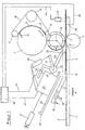
- a table top 1 is held on the in the direction of arrow A continuously lying flat plastic tube pieces with raised or added soils by means of conveyors, not shown be promoted.
- the bottoms that have been added or drawn up Soils in the manner shown in FIGS. 2 and 3 in the plane of the flat lying Hose pieces folded.
- a counter-pressure roller 4 and a suction roller 5 are mounted in the machine frame, which together form a pair of conveyor rollers and their nip in the area of Level of the top of the table 1 lies.
- the suction cylinder 5 is in its jacket provided approximately equal angular distances with rows of suction air holes 6.
- the inside of the suction cylinder 6 is the suction air in the usual way by a Rotary feedthrough, not shown, supplied.
- suction cylinder 5 Above the suction cylinder 5 is a knife and feed cylinder in the machine frame 7 stored to which the endless plastic web, not shown severed note 8 pressed by a strand 9 of an endless band of tapes 10 are circulating around the deflection rollers 11, 12, 13 mounted above the machine frame, of which the roller 13 can also be driven.
- the knife and feed cylinder 7 is in the usual way with a running along a surface line Knife 14 provided.
- a cooling plate 16 which ends with a is provided upward angled inlet side 17.
- the cooling plate 16, 17 is meandering and / or serpentine with coolant tubes provided by one through which the cooling medium flows.
- This cooling medium for example Water is introduced into the nozzle 18 through hose lines, not shown and withdrawn from the discharge pipe 19 again.
- an inclined guide 20 is held in the machine frame, on which a Heating unit 21 between stops 22, 23 of the guide 20 by a pressure medium piston cylinder unit 24 can be moved back and forth.
- the cooling unit is provided at its front end with a pipe 25 for blowing out warm air.
- a rotary valve 26 is arranged, the slide through an operating lever 27 in an open and closed position and intermediate positions is spendable.
- a pressure medium piston cylinder unit 28 provided on the one hand to the hot air unit 21 and on the other hand is articulated to the actuating lever 27.
- An exit of the rotary valve 26 opens into a tube 29 which carries a slot die 30 which in the Gap between the rollers 4, 5 is directed.
- the other exit of the rotary valve 26 opens into a pipe 32 which opens into the open or discharges the hot air.
- the suction cylinder 5 takes over the slip 8 in the manner shown Knife and conveyor cylinder 7 and places them in the correct position on the continuous Bag workpieces.
- the slip 8 and the workpiece 2 are to control hot air Blown in times that plasticizes the plastic material or in the way melts that the notes 8 stick to the workpieces 2.
- the hot air supply is via the pressure piston cylinder unit 28 by a Control device controlled clockwise. Furthermore, the slot die 30 can by the pressure medium piston cylinder unit 24 in its desired manner Set the distance to the nip.
- FIG. 2 shows a workpiece consisting of an added cross bottom, on which a bottom note 8 'is glued.
- a bag workpiece 2 with open bottoms can be seen in the the leading corner of the bottom of the valve label 8 '' glued is the valve hose when folding the side folds in a known manner results.
- the device shown in FIG. 1 is provided on both sides of the table 1, if at the same time both bottoms formed on the hose section 2 with bottom cover sheets 8 'are to be provided.
- the device described corresponds to the device according to DE 195 02 255 A1.
- the temperature signals from the temperature sensor are indicated by a signal line 41 of a control and regulating unit consisting of a computer 40 fed.
- This control and regulating unit 40 controls the temperature of the blown out heated air through a control line 42 which measures the temperature of the Electric heating elements of the heating unit 21 increased or decreased accordingly.
- the pair of rollers becomes the temperature of the glued area of the tube pieces 2 by a temperature sensor, in the illustrated embodiment by an infrared pyrometer 43 measured in the machine frame in the predetermined Distance above the outgoing workpieces is arranged.
- the measurement signals of the temperature sensor 43 are the control and Control unit 40 supplied to regulate the temperature of the slot die 30 blown warm air to the target temperature of the bonded area the temperature of the warm air is increased or decreased accordingly.
- the temperature of the table 1 is behind the nip of the rollers 4, 5 by a Temperature sensor 45 measured, the signals via a signal line 46 of the Control and regulating unit 40 are supplied.
- the temperature sensor 45 detects in essentially the temperature of the device, so that the control and regulation unit a preset temperature that is blown out of the slot die 30 Hot air can be done.
- the temperature of the Wide slot nozzle 30 blown hot air also by hand on the control and Set the control device, which may be useful for presetting the temperature can.
Landscapes
- Engineering & Computer Science (AREA)
- Mechanical Engineering (AREA)
- Physics & Mathematics (AREA)
- Thermal Sciences (AREA)
- Chemical & Material Sciences (AREA)
- Combustion & Propulsion (AREA)
- Lining Or Joining Of Plastics Or The Like (AREA)
- Making Paper Articles (AREA)
- Laminated Bodies (AREA)
- Adhesives Or Adhesive Processes (AREA)
- Labeling Devices (AREA)
Abstract
Description
- Fig. 1
- eine Seitenansicht der Vorrichtung zum Aufbringen und Aufkleben von Zetteln auf Werkstücke in schematischer Darstellung,
- Fig. 2
- eine Draufsicht auf einen zugelegten Kreuzboden mit aufgeklebtem Bodendeckblatt und
- Fig. 3
- einen aufgezogenen Boden mit auf einen Eckeinschlag aufgeklebten Ventilzettel.
Claims (3)
- Verfahren zum Regeln der Temperatur der erwärmten Luft in einer Vorrichtung zum Verkleben von Kunststoffolien, vorzugsweise zum Aufbringen von Zetteln (8) aus Kunststoffolie auf flachliegende Werkstücke (2) aus Kunststoffolie, z.B. von Ventilzetteln auf die aufgezogenen Bodenquadrate oder von Bodendeckblättern auf die zugelegten Böden von Kreuzbodenventilsäcken,
bestehend auseinem Gestell mit einer Platte oder einem Tisch (1), über den die Schlauch- oder Werkstücke (2) durch eine Fördereinrichtung kontinuierlich gefördert werden,einem in einem Spalt (3) der Tischplatte (1) angeordnetem und im Gestell gelagerten Förderwalzenpaar (4, 5), dessen Walzenspalt im wesentlichen mit der Tischoberfläche fluchtet und dessen untere Walze (4) eine Gegendruckwalze und dessen obere Walze ein Saugzylinder (6) ist,einem mit dem Saugzylinder (6) zusammenwirkenden Förderzylinder (7), der aufeinanderfolgend die Zettel (8) an den Saugzylinder (6) übergibt, und auseiner auf den Walzenspalt gerichteten Breitschlitzdüse (30), die in gesteuerter Weise erwärmte Luft in den Walzenspalt bläst,
dadurch gekennzeichnet,daß die Temperatur unmittelbar nach der Verklebung des verklebten Bereichs des Werkstücks, bei der eine gute Verklebung erfolgt, als Sollwert bestimmt wird unddaß die Temperatur der erwärmten Luft auf diesen Sollwert eingeregelt wird. - Verfahren nach Anspruch 1, dadurch gekennzeichnet, daß die Temperatur des verklebten Bereichs des Werkstücks als Istwert unmittelbar nach der Verklebung gemessen und die Temperatur der erwärmten Luft so lange erhöht oder erniedrigt wird, bist der Istwert der Messung dem Sollwert entspricht.
- Verfahren nach Anspruch 1 oder 2, dadurch gekennzeichnet, daß die Temperatur der Vorrichtung gemessen und eine dieser gemessenen Temperatur entsprechende Voreinstellung der Temperatur der erwärmten Luft erfolgt.
Applications Claiming Priority (2)
| Application Number | Priority Date | Filing Date | Title |
|---|---|---|---|
| DE19818720A DE19818720B4 (de) | 1998-04-27 | 1998-04-27 | Verfahren zum Verschweißen von kontinuierlich geförderten Kunststoffolien |
| DE19818720 | 1998-04-27 |
Publications (5)
| Publication Number | Publication Date |
|---|---|
| EP0953429A2 true EP0953429A2 (de) | 1999-11-03 |
| EP0953429A8 EP0953429A8 (de) | 2003-02-19 |
| EP0953429A3 EP0953429A3 (de) | 2003-03-05 |
| EP0953429B1 EP0953429B1 (de) | 2004-06-16 |
| EP0953429B8 EP0953429B8 (de) | 2004-10-13 |
Family
ID=7865900
Family Applications (1)
| Application Number | Title | Priority Date | Filing Date |
|---|---|---|---|
| EP99107044A Expired - Lifetime EP0953429B8 (de) | 1998-04-27 | 1999-04-09 | Verfahren zum Regeln der Temperatur der erwärmten Luft in einer Vorrichtung zum Heissluftverkleben von Kunststofffolien |
Country Status (11)
| Country | Link |
|---|---|
| US (1) | US6238326B1 (de) |
| EP (1) | EP0953429B8 (de) |
| JP (1) | JP4805434B2 (de) |
| KR (1) | KR100612105B1 (de) |
| AT (1) | ATE269202T1 (de) |
| BR (1) | BR9901299A (de) |
| CA (1) | CA2269175C (de) |
| CZ (1) | CZ300214B6 (de) |
| DE (1) | DE19818720B4 (de) |
| ES (1) | ES2221720T3 (de) |
| TW (1) | TW414780B (de) |
Cited By (6)
| Publication number | Priority date | Publication date | Assignee | Title |
|---|---|---|---|---|
| DE10222727A1 (de) * | 2002-05-23 | 2003-09-11 | Kuesters Eduard Maschf | Verfahren und Vorrichtung zum Laminieren von thermoplastischen Warenbahnen |
| WO2012119863A1 (de) * | 2011-03-04 | 2012-09-13 | Windmöller & Hölscher Kg | Verfahren und vorrichtung zum herstellen von säcken, deren wandungen gerecktes polyolefinmaterial enthalten |
| WO2016012218A1 (de) * | 2014-07-24 | 2016-01-28 | Windmöller & Hölscher Kg | HEIßLUFTSIEGELEINRICHTUNG UND VERFAHREN ZUM HEIßLUFTSIEGELN VON KUNSTSTOFFHALTIGER VERPACKUNG |
| EP3670171A1 (de) * | 2018-12-17 | 2020-06-24 | Starlinger & Co Gesellschaft m.b.H. | Vorrichtung und verfahren zum aufbringen von deckblättern auf zu kreuzböden vorgeformten enden von schlauchabschnitten |
| CN115285483A (zh) * | 2022-08-25 | 2022-11-04 | 赣州龙顺自动化设备有限公司 | 圆柱物品贴标机及贴标方法 |
| RU2792766C2 (ru) * | 2018-12-17 | 2023-03-23 | Штарлингер Унд Ко Гезелльшафт М.Б.Х. | Устройство и способ для нанесения покровных листов на предварительно формованные в крестовые донья концы отрезов рукава |
Families Citing this family (10)
| Publication number | Priority date | Publication date | Assignee | Title |
|---|---|---|---|---|
| DE10104002B4 (de) * | 2000-12-12 | 2009-12-31 | Windmöller & Hölscher Kg | Verfahren zum Temperieren zu verklebender Kunststofffolien sowie Vorrichtung zum Verkleben von Kunstfolie mit temperaturgesteuerter Transportwalze |
| ATA17172001A (de) * | 2000-12-12 | 2005-05-15 | Windmoeller & Hoelscher | Verfahren zum temperieren zu verklebender kunststofffolien sowie vorrichtung zum verkleben von kunststofffolie mit temperaturgesteuerter transportwalze |
| DE10109170B4 (de) * | 2001-02-26 | 2005-06-16 | Advanced Photonics Technologies Ag | Verfahren und Anordnung zur Herstellung eines geklebten Papier- oder Pappeproduktes |
| DE102004033356A1 (de) * | 2004-01-20 | 2005-08-11 | Röser, Jürgen | Geschenkartikel zur Mitteilung von Informationen |
| DE102007004244B4 (de) | 2007-01-23 | 2010-09-02 | Windmöller & Hölscher Kg | Vorrichtung und Verfahren zur Herstellung von Kunststoffsäcken |
| DE102008017442B4 (de) * | 2008-04-03 | 2013-01-17 | Windmöller & Hölscher Kg | Vorrichtung und Verfahren zur Herstellung von Säcken, welche Gewebe aus gereckten Kunststoffbändchen umfassen |
| CN104827710A (zh) * | 2015-05-29 | 2015-08-12 | 东莞豪顺家具有限公司 | 一种双层薄膜的压边装置 |
| US10604322B2 (en) | 2015-10-21 | 2020-03-31 | Societe Des Produits Nestle S.A. | Triple-folded hot air sealed thermoplastic bags |
| CN110385891B (zh) * | 2019-07-04 | 2021-07-20 | 河北盛世锦唐包装有限公司 | 一种新型方底阀口袋制袋机 |
| CN115195136A (zh) * | 2022-09-16 | 2022-10-18 | 河南新飞电器集团有限公司 | 一种用于布料热风熔接生产的自动焊专机 |
Family Cites Families (14)
| Publication number | Priority date | Publication date | Assignee | Title |
|---|---|---|---|---|
| CA997260A (en) * | 1973-12-13 | 1976-09-21 | Du Pont Of Canada Limited | Tube forming apparatus and process |
| JPS56161114A (en) * | 1980-05-16 | 1981-12-11 | Sumitomo Heavy Ind Ltd | Lamination device |
| JPS57164046U (de) * | 1981-04-10 | 1982-10-16 | ||
| US4834828A (en) * | 1987-04-30 | 1989-05-30 | Engineered Construction Components | Machine for welding roof membranes |
| US4850944A (en) * | 1988-04-15 | 1989-07-25 | Mobil Oil Corporation | Hot air hem sealer heat exchanger |
| GB8812361D0 (en) * | 1988-05-25 | 1988-06-29 | Kenrick & Jefferson Ltd | Heat sealing device |
| US4856260A (en) * | 1988-10-17 | 1989-08-15 | Baxter International Inc. | Apparatus for sealing a web of film in a packaging |
| DE4037020A1 (de) * | 1990-11-20 | 1992-05-21 | Koch Heinrich Plastmasch | Verfahren und vorrichtung zur regelung der temperatur der von einem schweissextruder plastifizierten kunststoffmasse |
| US5466326A (en) * | 1992-10-14 | 1995-11-14 | Hayssen Manufacturing Company | Continuous motion heat seal control |
| JPH06144415A (ja) * | 1992-11-06 | 1994-05-24 | Kao Corp | 容器のヒートシールライン制御装置 |
| DE19502255C2 (de) * | 1995-01-25 | 1996-11-28 | Windmoeller & Hoelscher | Vorrichtung zum Aufbringen von Zetteln aus Kunststoffolie auf flachliegende Werkstücke |
| NL1000888C2 (nl) * | 1995-07-26 | 1997-01-28 | Oce Nederland Bv | Temperatuurmeetsysteem en sensoreenheid van een dergelijk temperatuur- meetsysteem. |
| US5821505A (en) * | 1997-04-04 | 1998-10-13 | Unisys Corporation | Temperature control system for an electronic device which achieves a quick response by interposing a heater between the device and a heat sink |
| JP3960657B2 (ja) * | 1997-06-18 | 2007-08-15 | 大日本印刷株式会社 | 熱接着方法 |
-
1998
- 1998-04-27 DE DE19818720A patent/DE19818720B4/de not_active Expired - Lifetime
-
1999
- 1999-03-24 CZ CZ0106099A patent/CZ300214B6/cs not_active IP Right Cessation
- 1999-04-07 JP JP09979599A patent/JP4805434B2/ja not_active Expired - Lifetime
- 1999-04-09 AT AT99107044T patent/ATE269202T1/de active
- 1999-04-09 EP EP99107044A patent/EP0953429B8/de not_active Expired - Lifetime
- 1999-04-09 ES ES99107044T patent/ES2221720T3/es not_active Expired - Lifetime
- 1999-04-16 CA CA002269175A patent/CA2269175C/en not_active Expired - Lifetime
- 1999-04-20 TW TW088106346A patent/TW414780B/zh active
- 1999-04-24 KR KR1019990014716A patent/KR100612105B1/ko not_active Expired - Lifetime
- 1999-04-27 US US09/300,565 patent/US6238326B1/en not_active Expired - Lifetime
- 1999-04-27 BR BR9901299-5A patent/BR9901299A/pt not_active IP Right Cessation
Cited By (10)
| Publication number | Priority date | Publication date | Assignee | Title |
|---|---|---|---|---|
| DE10222727A1 (de) * | 2002-05-23 | 2003-09-11 | Kuesters Eduard Maschf | Verfahren und Vorrichtung zum Laminieren von thermoplastischen Warenbahnen |
| WO2012119863A1 (de) * | 2011-03-04 | 2012-09-13 | Windmöller & Hölscher Kg | Verfahren und vorrichtung zum herstellen von säcken, deren wandungen gerecktes polyolefinmaterial enthalten |
| WO2016012218A1 (de) * | 2014-07-24 | 2016-01-28 | Windmöller & Hölscher Kg | HEIßLUFTSIEGELEINRICHTUNG UND VERFAHREN ZUM HEIßLUFTSIEGELN VON KUNSTSTOFFHALTIGER VERPACKUNG |
| EP3670171A1 (de) * | 2018-12-17 | 2020-06-24 | Starlinger & Co Gesellschaft m.b.H. | Vorrichtung und verfahren zum aufbringen von deckblättern auf zu kreuzböden vorgeformten enden von schlauchabschnitten |
| WO2020126382A1 (de) | 2018-12-17 | 2020-06-25 | Starlinger & Co Gesellschaft M.B.H. | Vorrichtung und verfahren zum aufbringen von deckblättern auf zu kreuzböden vorgeformten enden von schlauchabschnitten |
| CN113226724A (zh) * | 2018-12-17 | 2021-08-06 | 史太林格有限责任公司 | 用于将盖片敷设到袋囊区段的预成型为交叉底部的端部上的装置和方法 |
| US11446881B2 (en) | 2018-12-17 | 2022-09-20 | Starlinger & Co Gesselschaft M.B.H | Apparatus and method for applying cover sheets to ends, preformed into cross bottoms, of tube portions |
| RU2792766C2 (ru) * | 2018-12-17 | 2023-03-23 | Штарлингер Унд Ко Гезелльшафт М.Б.Х. | Устройство и способ для нанесения покровных листов на предварительно формованные в крестовые донья концы отрезов рукава |
| CN115285483A (zh) * | 2022-08-25 | 2022-11-04 | 赣州龙顺自动化设备有限公司 | 圆柱物品贴标机及贴标方法 |
| CN115285483B (zh) * | 2022-08-25 | 2024-03-22 | 赣州龙顺自动化设备有限公司 | 圆柱物品贴标机及贴标方法 |
Also Published As
| Publication number | Publication date |
|---|---|
| DE19818720B4 (de) | 2008-08-07 |
| KR100612105B1 (ko) | 2006-08-11 |
| ATE269202T1 (de) | 2004-07-15 |
| EP0953429A8 (de) | 2003-02-19 |
| ES2221720T3 (es) | 2005-01-01 |
| CZ300214B6 (cs) | 2009-03-18 |
| JPH11320715A (ja) | 1999-11-24 |
| CZ106099A3 (cs) | 1999-11-17 |
| BR9901299A (pt) | 2001-10-02 |
| US6238326B1 (en) | 2001-05-29 |
| KR19990083455A (ko) | 1999-11-25 |
| EP0953429B1 (de) | 2004-06-16 |
| DE19818720A1 (de) | 1999-11-04 |
| CA2269175A1 (en) | 1999-10-27 |
| EP0953429B8 (de) | 2004-10-13 |
| TW414780B (en) | 2000-12-11 |
| JP4805434B2 (ja) | 2011-11-02 |
| CA2269175C (en) | 2008-01-29 |
Similar Documents
| Publication | Publication Date | Title |
|---|---|---|
| DE19502255C2 (de) | Vorrichtung zum Aufbringen von Zetteln aus Kunststoffolie auf flachliegende Werkstücke | |
| EP0953429B1 (de) | Verfahren zum Regeln der Temperatur der erwärmten Luft in einer Vorrichtung zum Heissluftverkleben von Kunststofffolien | |
| DE69510149T2 (de) | Heissschweissvorrichtung | |
| DE2600030A1 (de) | Verfahren und vorrichtung zum verpacken von einheiten in flexiblem bandmaterial | |
| EP0406223B1 (de) | Vorrichtung zum Verschweissen von Kunststoffbahnen | |
| EP2049327A1 (de) | Verfahren zum herstellen von verpackungsbeuteln mit verstärktem bodenbereich sowie vorrichtung zur durchführung des verfahrens | |
| DE2533566A1 (de) | Verfahren und vorrichtung zur herstellung einer breiten warenbahn | |
| DE2902879A1 (de) | Verfahren zum kontinuierlichen beschichten von einzelnen spannbeton- stahlstaeben und vorrichtungen sowie ein system zur durchfuehrung des verfahrens | |
| EP0240827B1 (de) | Vorrichtung zur Herstellung von Luftpolster-Versandtaschen | |
| EP2125353B1 (de) | Vorrichtung und verfahren zur herstellung von kunststoffsäcken | |
| DE69905886T2 (de) | Vorrichtung zum aufbringen von etiketten auf getränkekisten | |
| DE4311514B4 (de) | Vorrichtung zum Siegeln von Folienbahnen aus thermoplastischem Kunststoff | |
| DE10104002B4 (de) | Verfahren zum Temperieren zu verklebender Kunststofffolien sowie Vorrichtung zum Verkleben von Kunstfolie mit temperaturgesteuerter Transportwalze | |
| EP0812257B1 (de) | Verfahren und vorrichtung zum beheizen einer bewegten bahn, insbesondere wellpappenbahn | |
| DE2914696C2 (de) | Vorrichtung zum Aufbringen von mit einem Kleber versehenen Reiterbändern auf die flachliegenden Stirnkanten von Schlauchabschnitten oder Säcken | |
| EP0806346A2 (de) | Mit einer Schlauchformeinrichtung versehene Verpackungsmaschine | |
| EP4395980A1 (de) | Applikationsstation und verfahren zum aufbringen eines ersten flachen werkstücks auf ein zweites werkstück | |
| DE1527911C3 (de) | Verfahren und Vorrichtung zum Aufbringen eines Streifens aus thermoplastischem Material auf flache Blechstücke | |
| DE10134255B4 (de) | Verpackungsmaschine | |
| CH619175A5 (en) | Mobile hand welding device | |
| DE19732993C2 (de) | Vorrichtung zum Applizieren eines endlosen Streifens auf eine Endlosbahn | |
| DE20206497U1 (de) | Sackverschliesseinheit | |
| DE2954251C2 (de) | Vorrichtung zum Aufbringen von mit einem Kleber versehenen Reiterbändern auf die flachliegenden Stirnkanten von Schlauchabschnitten oder Säcken | |
| DE1922432A1 (de) | Maschine zum Anbringen von Lesezeichen an gehefteten Buchbloecken | |
| CH683422A5 (de) | Verfahren und Vorrichtung zum Zusammensetzen von Fell-, Leder- oder Textilstreifen zu einem Band. |
Legal Events
| Date | Code | Title | Description |
|---|---|---|---|
| PUAI | Public reference made under article 153(3) epc to a published international application that has entered the european phase |
Free format text: ORIGINAL CODE: 0009012 |
|
| AK | Designated contracting states |
Kind code of ref document: A2 Designated state(s): AT BE CH CY DE DK ES FI FR GB GR IE IT LI LU MC NL PT SE |
|
| AX | Request for extension of the european patent |
Free format text: AL;LT;LV;MK;RO;SI |
|
| RAP1 | Party data changed (applicant data changed or rights of an application transferred) |
Owner name: WINDMOELLER & HOELSCHER |
|
| PUAL | Search report despatched |
Free format text: ORIGINAL CODE: 0009013 |
|
| RAP1 | Party data changed (applicant data changed or rights of an application transferred) |
Owner name: STARLINGER & CO. GES.M.B.H. Owner name: WINDMOELLER & HOELSCHER |
|
| AK | Designated contracting states |
Kind code of ref document: A3 Designated state(s): AT BE CH CY DE DK ES FI FR GB GR IE IT LI LU MC NL PT SE Designated state(s): AT BE CH CY DE DK ES FI FR GB GR IE IT LI LU MC NL PT SE |
|
| AX | Request for extension of the european patent |
Extension state: AL LT LV MK RO SI |
|
| RIC1 | Information provided on ipc code assigned before grant |
Ipc: 7B 31B 19/84 B Ipc: 7B 31B 19/64 B Ipc: 7B 29C 65/00 B Ipc: 7B 31B 1/84 B Ipc: 7B 29C 65/10 A |
|
| 17P | Request for examination filed |
Effective date: 20030321 |
|
| 17Q | First examination report despatched |
Effective date: 20030415 |
|
| GRAP | Despatch of communication of intention to grant a patent |
Free format text: ORIGINAL CODE: EPIDOSNIGR1 |
|
| AKX | Designation fees paid |
Designated state(s): AT ES FR GB IT |
|
| RTI1 | Title (correction) |
Free format text: PROCESS FOR CONTROLLING THE TEMPERATURE OF THE HEATED AIR IN AN APPARATUS FOR HOT AIR WELDING OF SYNTHETIC SHEETS |
|
| REG | Reference to a national code |
Ref country code: DE Ref legal event code: 8566 |
|
| GRAS | Grant fee paid |
Free format text: ORIGINAL CODE: EPIDOSNIGR3 |
|
| GRAA | (expected) grant |
Free format text: ORIGINAL CODE: 0009210 |
|
| AK | Designated contracting states |
Kind code of ref document: B1 Designated state(s): AT ES FR GB IT |
|
| REG | Reference to a national code |
Ref country code: GB Ref legal event code: FG4D Free format text: NOT ENGLISH |
|
| RIN2 | Information on inventor provided after grant (corrected) |
Inventor name: HENZE, RAINER Inventor name: BURGER, JAN Inventor name: STARLINGER-HUEMER, FRANZ X. ING. |
|
| GBT | Gb: translation of ep patent filed (gb section 77(6)(a)/1977) |
Effective date: 20040910 |
|
| RIN2 | Information on inventor provided after grant (corrected) |
Inventor name: HENZE, RAINER Inventor name: BURGER, JAN Inventor name: STARLINGER-HUEMER, FRANZ X. ING. |
|
| REG | Reference to a national code |
Ref country code: ES Ref legal event code: FG2A Ref document number: 2221720 Country of ref document: ES Kind code of ref document: T3 |
|
| ET | Fr: translation filed | ||
| PLBE | No opposition filed within time limit |
Free format text: ORIGINAL CODE: 0009261 |
|
| STAA | Information on the status of an ep patent application or granted ep patent |
Free format text: STATUS: NO OPPOSITION FILED WITHIN TIME LIMIT |
|
| 26N | No opposition filed |
Effective date: 20050317 |
|
| REG | Reference to a national code |
Ref country code: FR Ref legal event code: PLFP Year of fee payment: 18 |
|
| REG | Reference to a national code |
Ref country code: FR Ref legal event code: PLFP Year of fee payment: 19 |
|
| REG | Reference to a national code |
Ref country code: FR Ref legal event code: PLFP Year of fee payment: 20 |
|
| PGFP | Annual fee paid to national office [announced via postgrant information from national office to epo] |
Ref country code: ES Payment date: 20180522 Year of fee payment: 20 |
|
| PGFP | Annual fee paid to national office [announced via postgrant information from national office to epo] |
Ref country code: AT Payment date: 20180426 Year of fee payment: 20 Ref country code: FR Payment date: 20180426 Year of fee payment: 20 Ref country code: IT Payment date: 20180420 Year of fee payment: 20 |
|
| PGFP | Annual fee paid to national office [announced via postgrant information from national office to epo] |
Ref country code: GB Payment date: 20180404 Year of fee payment: 20 |
|
| REG | Reference to a national code |
Ref country code: GB Ref legal event code: PE20 Expiry date: 20190408 |
|
| REG | Reference to a national code |
Ref country code: AT Ref legal event code: MK07 Ref document number: 269202 Country of ref document: AT Kind code of ref document: T Effective date: 20190409 |
|
| PG25 | Lapsed in a contracting state [announced via postgrant information from national office to epo] |
Ref country code: GB Free format text: LAPSE BECAUSE OF EXPIRATION OF PROTECTION Effective date: 20190408 |
|
| REG | Reference to a national code |
Ref country code: ES Ref legal event code: FD2A Effective date: 20200902 |
|
| PG25 | Lapsed in a contracting state [announced via postgrant information from national office to epo] |
Ref country code: ES Free format text: LAPSE BECAUSE OF EXPIRATION OF PROTECTION Effective date: 20190410 |