EP2680907B1 - Closure piece for a powder syringe, and powder syringe - Google Patents
Closure piece for a powder syringe, and powder syringe Download PDFInfo
- Publication number
- EP2680907B1 EP2680907B1 EP12707475.5A EP12707475A EP2680907B1 EP 2680907 B1 EP2680907 B1 EP 2680907B1 EP 12707475 A EP12707475 A EP 12707475A EP 2680907 B1 EP2680907 B1 EP 2680907B1
- Authority
- EP
- European Patent Office
- Prior art keywords
- channel
- closure piece
- powder
- closure
- powder syringe
- Prior art date
- Legal status (The legal status is an assumption and is not a legal conclusion. Google has not performed a legal analysis and makes no representation as to the accuracy of the status listed.)
- Active
Links
- 239000000843 powder Substances 0.000 title claims description 117
- 238000007789 sealing Methods 0.000 claims description 46
- 239000012528 membrane Substances 0.000 claims description 17
- 239000000126 substance Substances 0.000 claims description 17
- 230000008719 thickening Effects 0.000 claims description 7
- 230000035515 penetration Effects 0.000 claims description 6
- 230000004913 activation Effects 0.000 claims description 5
- 230000009977 dual effect Effects 0.000 claims description 4
- 230000000149 penetrating effect Effects 0.000 claims description 2
- 239000000243 solution Substances 0.000 description 14
- 239000012530 fluid Substances 0.000 description 13
- 239000002904 solvent Substances 0.000 description 11
- 239000000463 material Substances 0.000 description 8
- 206010053648 Vascular occlusion Diseases 0.000 description 7
- 238000005054 agglomeration Methods 0.000 description 7
- 230000002776 aggregation Effects 0.000 description 7
- 230000008878 coupling Effects 0.000 description 5
- 238000010168 coupling process Methods 0.000 description 5
- 238000005859 coupling reaction Methods 0.000 description 5
- 238000003860 storage Methods 0.000 description 5
- 230000003213 activating effect Effects 0.000 description 3
- 238000002347 injection Methods 0.000 description 3
- 239000007924 injection Substances 0.000 description 3
- 238000005507 spraying Methods 0.000 description 3
- CIWBSHSKHKDKBQ-JLAZNSOCSA-N Ascorbic acid Chemical compound OC[C@H](O)[C@H]1OC(=O)C(O)=C1O CIWBSHSKHKDKBQ-JLAZNSOCSA-N 0.000 description 2
- 230000009471 action Effects 0.000 description 2
- 239000004480 active ingredient Substances 0.000 description 2
- 239000013543 active substance Substances 0.000 description 2
- 238000005520 cutting process Methods 0.000 description 2
- 238000006073 displacement reaction Methods 0.000 description 2
- 238000004108 freeze drying Methods 0.000 description 2
- 239000011521 glass Substances 0.000 description 2
- 238000004519 manufacturing process Methods 0.000 description 2
- 230000013011 mating Effects 0.000 description 2
- 239000002245 particle Substances 0.000 description 2
- 239000012254 powdered material Substances 0.000 description 2
- 230000000717 retained effect Effects 0.000 description 2
- 241001631457 Cannula Species 0.000 description 1
- ZZZCUOFIHGPKAK-UHFFFAOYSA-N D-erythro-ascorbic acid Natural products OCC1OC(=O)C(O)=C1O ZZZCUOFIHGPKAK-UHFFFAOYSA-N 0.000 description 1
- 229930003268 Vitamin C Natural products 0.000 description 1
- 230000004323 axial length Effects 0.000 description 1
- 230000008901 benefit Effects 0.000 description 1
- 239000003795 chemical substances by application Substances 0.000 description 1
- 238000004891 communication Methods 0.000 description 1
- 230000006835 compression Effects 0.000 description 1
- 238000007906 compression Methods 0.000 description 1
- 239000003814 drug Substances 0.000 description 1
- 229940079593 drug Drugs 0.000 description 1
- 230000000694 effects Effects 0.000 description 1
- 239000013013 elastic material Substances 0.000 description 1
- 238000001704 evaporation Methods 0.000 description 1
- 238000003698 laser cutting Methods 0.000 description 1
- 239000007788 liquid Substances 0.000 description 1
- 230000007774 longterm Effects 0.000 description 1
- 238000012792 lyophilization process Methods 0.000 description 1
- 230000014759 maintenance of location Effects 0.000 description 1
- 238000000034 method Methods 0.000 description 1
- 239000008188 pellet Substances 0.000 description 1
- 239000000546 pharmaceutical excipient Substances 0.000 description 1
- 230000002265 prevention Effects 0.000 description 1
- 230000008569 process Effects 0.000 description 1
- 230000000452 restraining effect Effects 0.000 description 1
- 239000002195 soluble material Substances 0.000 description 1
- 239000007921 spray Substances 0.000 description 1
- 235000019154 vitamin C Nutrition 0.000 description 1
- 239000011718 vitamin C Substances 0.000 description 1
Images


Classifications
-
- A—HUMAN NECESSITIES
- A61—MEDICAL OR VETERINARY SCIENCE; HYGIENE
- A61M—DEVICES FOR INTRODUCING MEDIA INTO, OR ONTO, THE BODY; DEVICES FOR TRANSDUCING BODY MEDIA OR FOR TAKING MEDIA FROM THE BODY; DEVICES FOR PRODUCING OR ENDING SLEEP OR STUPOR
- A61M5/00—Devices for bringing media into the body in a subcutaneous, intra-vascular or intramuscular way; Accessories therefor, e.g. filling or cleaning devices, arm-rests
- A61M5/178—Syringes
- A61M5/31—Details
-
- A—HUMAN NECESSITIES
- A61—MEDICAL OR VETERINARY SCIENCE; HYGIENE
- A61M—DEVICES FOR INTRODUCING MEDIA INTO, OR ONTO, THE BODY; DEVICES FOR TRANSDUCING BODY MEDIA OR FOR TAKING MEDIA FROM THE BODY; DEVICES FOR PRODUCING OR ENDING SLEEP OR STUPOR
- A61M5/00—Devices for bringing media into the body in a subcutaneous, intra-vascular or intramuscular way; Accessories therefor, e.g. filling or cleaning devices, arm-rests
- A61M5/178—Syringes
- A61M5/28—Syringe ampoules or carpules, i.e. ampoules or carpules provided with a needle
- A61M5/284—Syringe ampoules or carpules, i.e. ampoules or carpules provided with a needle comprising means for injection of two or more media, e.g. by mixing
-
- A—HUMAN NECESSITIES
- A61—MEDICAL OR VETERINARY SCIENCE; HYGIENE
- A61M—DEVICES FOR INTRODUCING MEDIA INTO, OR ONTO, THE BODY; DEVICES FOR TRANSDUCING BODY MEDIA OR FOR TAKING MEDIA FROM THE BODY; DEVICES FOR PRODUCING OR ENDING SLEEP OR STUPOR
- A61M5/00—Devices for bringing media into the body in a subcutaneous, intra-vascular or intramuscular way; Accessories therefor, e.g. filling or cleaning devices, arm-rests
- A61M5/178—Syringes
- A61M5/28—Syringe ampoules or carpules, i.e. ampoules or carpules provided with a needle
- A61M5/285—Syringe ampoules or carpules, i.e. ampoules or carpules provided with a needle with sealing means to be broken or opened
- A61M5/286—Syringe ampoules or carpules, i.e. ampoules or carpules provided with a needle with sealing means to be broken or opened upon internal pressure increase, e.g. pierced or burst
-
- A—HUMAN NECESSITIES
- A61—MEDICAL OR VETERINARY SCIENCE; HYGIENE
- A61J—CONTAINERS SPECIALLY ADAPTED FOR MEDICAL OR PHARMACEUTICAL PURPOSES; DEVICES OR METHODS SPECIALLY ADAPTED FOR BRINGING PHARMACEUTICAL PRODUCTS INTO PARTICULAR PHYSICAL OR ADMINISTERING FORMS; DEVICES FOR ADMINISTERING FOOD OR MEDICINES ORALLY; BABY COMFORTERS; DEVICES FOR RECEIVING SPITTLE
- A61J1/00—Containers specially adapted for medical or pharmaceutical purposes
- A61J1/14—Details; Accessories therefor
- A61J1/1406—Septums, pierceable membranes
-
- A—HUMAN NECESSITIES
- A61—MEDICAL OR VETERINARY SCIENCE; HYGIENE
- A61J—CONTAINERS SPECIALLY ADAPTED FOR MEDICAL OR PHARMACEUTICAL PURPOSES; DEVICES OR METHODS SPECIALLY ADAPTED FOR BRINGING PHARMACEUTICAL PRODUCTS INTO PARTICULAR PHYSICAL OR ADMINISTERING FORMS; DEVICES FOR ADMINISTERING FOOD OR MEDICINES ORALLY; BABY COMFORTERS; DEVICES FOR RECEIVING SPITTLE
- A61J1/00—Containers specially adapted for medical or pharmaceutical purposes
- A61J1/14—Details; Accessories therefor
- A61J1/20—Arrangements for transferring or mixing fluids, e.g. from vial to syringe
- A61J1/2003—Accessories used in combination with means for transfer or mixing of fluids, e.g. for activating fluid flow, separating fluids, filtering fluid or venting
- A61J1/202—Separating means
- A61J1/2041—Separating means having removable plugs
-
- A—HUMAN NECESSITIES
- A61—MEDICAL OR VETERINARY SCIENCE; HYGIENE
- A61M—DEVICES FOR INTRODUCING MEDIA INTO, OR ONTO, THE BODY; DEVICES FOR TRANSDUCING BODY MEDIA OR FOR TAKING MEDIA FROM THE BODY; DEVICES FOR PRODUCING OR ENDING SLEEP OR STUPOR
- A61M5/00—Devices for bringing media into the body in a subcutaneous, intra-vascular or intramuscular way; Accessories therefor, e.g. filling or cleaning devices, arm-rests
- A61M5/178—Syringes
- A61M5/28—Syringe ampoules or carpules, i.e. ampoules or carpules provided with a needle
- A61M5/285—Syringe ampoules or carpules, i.e. ampoules or carpules provided with a needle with sealing means to be broken or opened
- A61M5/286—Syringe ampoules or carpules, i.e. ampoules or carpules provided with a needle with sealing means to be broken or opened upon internal pressure increase, e.g. pierced or burst
- A61M2005/287—Syringe ampoules or carpules, i.e. ampoules or carpules provided with a needle with sealing means to be broken or opened upon internal pressure increase, e.g. pierced or burst by displacing occluding plugs
-
- A—HUMAN NECESSITIES
- A61—MEDICAL OR VETERINARY SCIENCE; HYGIENE
- A61M—DEVICES FOR INTRODUCING MEDIA INTO, OR ONTO, THE BODY; DEVICES FOR TRANSDUCING BODY MEDIA OR FOR TAKING MEDIA FROM THE BODY; DEVICES FOR PRODUCING OR ENDING SLEEP OR STUPOR
- A61M5/00—Devices for bringing media into the body in a subcutaneous, intra-vascular or intramuscular way; Accessories therefor, e.g. filling or cleaning devices, arm-rests
- A61M5/178—Syringes
- A61M5/31—Details
- A61M2005/3103—Leak prevention means for distal end of syringes, i.e. syringe end for mounting a needle
- A61M2005/3104—Caps for syringes without needle
-
- A—HUMAN NECESSITIES
- A61—MEDICAL OR VETERINARY SCIENCE; HYGIENE
- A61M—DEVICES FOR INTRODUCING MEDIA INTO, OR ONTO, THE BODY; DEVICES FOR TRANSDUCING BODY MEDIA OR FOR TAKING MEDIA FROM THE BODY; DEVICES FOR PRODUCING OR ENDING SLEEP OR STUPOR
- A61M5/00—Devices for bringing media into the body in a subcutaneous, intra-vascular or intramuscular way; Accessories therefor, e.g. filling or cleaning devices, arm-rests
- A61M5/178—Syringes
- A61M5/31—Details
- A61M2005/3103—Leak prevention means for distal end of syringes, i.e. syringe end for mounting a needle
- A61M2005/3106—Plugs for syringes without needle
-
- A—HUMAN NECESSITIES
- A61—MEDICAL OR VETERINARY SCIENCE; HYGIENE
- A61M—DEVICES FOR INTRODUCING MEDIA INTO, OR ONTO, THE BODY; DEVICES FOR TRANSDUCING BODY MEDIA OR FOR TAKING MEDIA FROM THE BODY; DEVICES FOR PRODUCING OR ENDING SLEEP OR STUPOR
- A61M5/00—Devices for bringing media into the body in a subcutaneous, intra-vascular or intramuscular way; Accessories therefor, e.g. filling or cleaning devices, arm-rests
- A61M5/178—Syringes
- A61M5/31—Details
- A61M2005/3117—Means preventing contamination of the medicament compartment of a syringe
- A61M2005/3118—Means preventing contamination of the medicament compartment of a syringe via the distal end of a syringe, i.e. syringe end for mounting a needle cannula
- A61M2005/312—Means preventing contamination of the medicament compartment of a syringe via the distal end of a syringe, i.e. syringe end for mounting a needle cannula comprising sealing means, e.g. severable caps, to be removed prior to injection by, e.g. tearing or twisting
-
- A—HUMAN NECESSITIES
- A61—MEDICAL OR VETERINARY SCIENCE; HYGIENE
- A61M—DEVICES FOR INTRODUCING MEDIA INTO, OR ONTO, THE BODY; DEVICES FOR TRANSDUCING BODY MEDIA OR FOR TAKING MEDIA FROM THE BODY; DEVICES FOR PRODUCING OR ENDING SLEEP OR STUPOR
- A61M5/00—Devices for bringing media into the body in a subcutaneous, intra-vascular or intramuscular way; Accessories therefor, e.g. filling or cleaning devices, arm-rests
- A61M5/178—Syringes
- A61M5/31—Details
- A61M5/32—Needles; Details of needles pertaining to their connection with syringe or hub; Accessories for bringing the needle into, or holding the needle on, the body; Devices for protection of needles
- A61M5/34—Constructions for connecting the needle, e.g. to syringe nozzle or needle hub
- A61M5/344—Constructions for connecting the needle, e.g. to syringe nozzle or needle hub using additional parts, e.g. clamping rings or collets
- A61M5/345—Adaptors positioned between needle hub and syringe nozzle
-
- A—HUMAN NECESSITIES
- A61—MEDICAL OR VETERINARY SCIENCE; HYGIENE
- A61M—DEVICES FOR INTRODUCING MEDIA INTO, OR ONTO, THE BODY; DEVICES FOR TRANSDUCING BODY MEDIA OR FOR TAKING MEDIA FROM THE BODY; DEVICES FOR PRODUCING OR ENDING SLEEP OR STUPOR
- A61M5/00—Devices for bringing media into the body in a subcutaneous, intra-vascular or intramuscular way; Accessories therefor, e.g. filling or cleaning devices, arm-rests
- A61M5/178—Syringes
- A61M5/31—Details
- A61M5/32—Needles; Details of needles pertaining to their connection with syringe or hub; Accessories for bringing the needle into, or holding the needle on, the body; Devices for protection of needles
- A61M5/34—Constructions for connecting the needle, e.g. to syringe nozzle or needle hub
- A61M5/347—Constructions for connecting the needle, e.g. to syringe nozzle or needle hub rotatable, e.g. bayonet or screw
Description
Die Erfindung betrifft einen Verschluss für eine Pulverspritze gemäß Oberbegriff des Anspruchs 1 sowie eine Pulverspritze gemäß Oberbegriff des Anspruchs 13.The invention relates to a closure for a powder syringe according to the preamble of
Verschlüsse und Pulverspritzen der hier angesprochenen Art sind bekannt. Bevorzugt kommen als Pulverspritzen Doppelkammersysteme zur Anwendung, welche eine proximale Kammer und eine distale Kammer aufweisen. Die proximale Kammer umfasst typischerweise ein flüssiges Lösungsmittel und ist durch einen Mittelstopfen von der distalen Kammer getrennt, welche ein in dem Lösungsmittel lösliches Material aufweist. Dies kann ein Pulver sein, welches eine Rieselneigung aufweist. Bekannte Verschlüsse weisen einen Kanal auf, der einerseits mit der distalen Kammer in Fluidverbindung steht und andererseits mit einer auf den Verschluss aufgesetzten Kanüle oder Spritzennadel in Fluidverbindung gebrachte werden kann. Es ist möglich, dass Pulver in den Bereich des in den Verschluss vorgesehenen Kanals beziehungsweise in den Kanal selbst gelangt. Dabei können dort Agglomerate des pulverförmigen Materials entstehen, welche gegebenenfalls nicht mehr lösbar sind. Der Kanal ist dann verstopft, so dass das Doppelkammersystem nicht mehr verwendet werden kann. Das gleiche Problem besteht auch bei einer Pulverspritze, die nicht als Doppelkammersystem ausgebildet ist, aber einen Verschluss mit einem Kanal aufweist. Auch in diesem Fall können sich in dem Kanal Pulveragglomerate bilden, welche diesen verstopfen.Closures and powder spraying of the type discussed here are known. Preference is given to using dual-chamber systems as powder syringes, which have a proximal chamber and a distal chamber. The proximal chamber typically comprises a liquid solvent and is separated from the distal chamber by a center plug having a solvent-soluble material. This may be a powder that has a trickle tendency. Known closures have a channel that is in fluid communication with the distal chamber on the one hand, and that can be fluidly connected to a cannula or syringe needle placed on the closure on the other hand. It is possible for powder to reach the region of the channel provided in the closure or into the channel itself. In this case, there may arise agglomerates of the powdery material, which may not be solvable. The channel is then blocked so that the dual chamber system can no longer be used. The same problem also exists with a powder syringe, which is not formed as a dual-chamber system, but has a closure with a channel. In this case, too, powder agglomerates may form in the channel which block it.
Eine aus dem Stand der Technik bekannte Pulverspritze ist in
Aufgabe der Erfindung ist es daher, einen Verschluss für eine Pulverspritze sowie eine Pulverspritze zu schaffen, welche die beschriebenen Nachteile nicht aufweist.The object of the invention is therefore to provide a closure for a powder syringe and a powder syringe, which does not have the disadvantages described.
Die Aufgabe wird gelöst, indem ein Verschluss mit den Merkmalen des Anspruchs 1 geschaffen wird. Der Verschluss für eine Pulverspritze umfasst einen Grundkörper und ein Dichtelement, welches an dem Grundkörper so angeordnet ist, dass es an einer distalen Öffnung einer Pulverspitze dichtend anliegt, wenn der Verschluss auf der Pulverspritze in seiner Verschließposition angeordnet ist. Der Verschluss weist außerdem einen Kanal auf, welcher den Grundkörper und das Dichtelement durchsetzt. Dieser weist ein proximales und ein distales Ende auf. Der Verschluss zeichnet sich durch ein Rückhalteelement aus, welches so ausgebildet und/oder anordenbar ist, dass vor einer Aktivierung der Pulverspritze ein Eindringen von Pulver aus einer Kammer der Pulverspritze in den Kanal weitgehend verhindert wird, wenn der Verschluss in seiner Verschließposition auf der Pulverspritze angeordnet ist. Eine weitgehende Verhinderung spricht an, dass höchstens so viel Pulver in den Kanal eindringen kann, dass eine Agglomeratbildung ausgeschlossen ist. Das Rückhalteelement ist entweder so ausgebildet, dass es ein Eindringen des pulverförmigen Materials in den Kanal des Verschlusses verhindert, wenn dieser in seiner Verschließposition angeordnet ist, oder es kann - gegebenenfalls auch getrennt von den restlichen Elementen des Verschlusses - so angeordnet werden, dass es ein Eindringen des Pulvers in den Kanal verhindert. Bevorzugt wird das Rückhalteelement so angeordnet, dass Restvolumina, in denen eine Agglomeratbildung möglich ist, minimiert oder besonders bevorzugt vollständig vermieden werden. Das Rückhalteelement kann auch zugleich entsprechend ausgebildet und entsprechend anordenbar sein. Durch das Rückhalteelement wird der Kanal quasi von der Kammer, in welcher das Pulver vorliegt, getrennt, so dass sich in dem Kanal keine Agglomerate bilden können, welche denselben verstopfen könnten. Die Funktion einer mit dem Verschluss ausgestatteten Pulverspritze ist daher auch über eine lange Lagerzeit gewährleistet. Es muss auch nicht darauf geachtet werden, in welcher Lage eine mit dem Verschluss verschlossene Pulverspritze gelagert wird, weil aufgrund des Rückhalteelements in keiner Lage Pulver oder zumindest keine für eine Agglomeratbildung ausreichenden Pulvermenge in den Kanal eindringen kann.The object is achieved by providing a closure with the features of
Bevorzugt wird ein Verschluss, der eine Verschlusskappe zum Verschließen des distalen Endes des Kanals umfasst, wobei die Verschlusskappe einen stabförmigen Vorsprung aufweist. Dieser durchsetzt den Kanal, wobei an ihm das Rückhalteelement vorgesehen ist. Der stabförmige Vorsprung verschließt quasi den Kanal. Dies hat den Vorteil, dass bei einer Entfernung der Verschlusskappe zur Aktivierung der Pulverspritze zugleich auch der Kanal freigegeben wird, ohne dass es weiterer Maßnahmen bedarf. Außerdem sind bei einem Verschluss, welcher ohnehin eine Verschlusskappe umfasst, keine weiteren Elemente nötig.Preferred is a closure comprising a closure cap for closing the distal end of the channel, the closure cap having a rod-shaped projection. This passes through the channel, wherein the retaining element is provided on it. The rod-shaped projection virtually closes the channel. This has the advantage that at a distance of the cap for activating the powder syringe at the same time the channel is released, without the need for further action. In addition, in a closure, which already includes a cap, no further elements necessary.
Bevorzugt wird auch ein Verschluss, bei dem das Rückhalteelement als vorzugsweise geschlitzte Membran ausgebildet ist. Die Membran kann durch die beim Aktivieren der Spritze beziehungsweise zur Abgabe des Spritzeninhalts an einen Patienten aufgebauten Druckkräfte aufgesprengt, verformt und mit Hilfe einer nadelförmigen Vorrichtung aufgestochen oder im Bereich eines Schlitzes aufgeweitet werden, um den Kanal freizugeben.Also preferred is a closure in which the retaining element is designed as a preferably slotted membrane. The membrane can be burst open by the pressure forces built up when activating the syringe or for delivering the contents of the syringe to a patient, be shaped and pierced with the aid of a needle-shaped device or widened in the area of a slit to release the channel.
Es wird auch ein Verschluss bevorzugt, bei dem das Rückhalteelement als entlang des Kanals verlagerbares Element ausgebildet ist. Bevorzugt ist dieses quasi im Lagerzustand der Spritze an dem proximalen Ende des Kanals angeordnet und verschließt diesen. Zur Aktivierung der Pulverspritze kann das Element entlang des Kanals zu dessen distalem Ende verlagert werden, wo es schließlich aus dem Kanal austritt und damit denselben freigibt.It is also preferred a closure in which the retaining element is formed as displaceable along the channel element. This is preferably arranged in the storage state of the syringe at the proximal end of the channel and closes it. To activate the powder syringe, the element can be displaced along the channel to its distal end, where it finally exits the channel and thus releases it.
Bevorzugt wird auch ein Verschluss, bei dem das Rückhalteelement eine lösliche Substanz umfasst. Besonders bevorzugt umfasst das Rückhaltement eine lyophilisierte Substanz. Diese kann beim Aktivieren der Spritze durch ein Lösungsmittel gelöst werden, so dass der Kanal freigegeben wird.Also preferred is a closure in which the retaining element comprises a soluble substance. Particularly preferably, the retention element comprises a lyophilized substance. This can be solved by activating the syringe by a solvent, so that the channel is released.
Schließlich wird noch ein Verschluss bevorzugt, bei welchem das Rückhalteelement eine Verschlussscheibe umfasst, die so ausgebildet ist, dass sie an einer Verengung einer Pulverspritze dichtend anliegen kann. Auf diese Weise kann sie ein Eindringen von Pulver in den Kanal verhindern. Die Verschlussscheibe ist insbesondere im Bereich der Verengung der Pulverspritze so anördenbar, dass vor einer Aktivierung der Pulverspritze kein Pulver in den Kanal eindringen kann. Bei einer Aktivierung der Pulverspritze wird die Verschlussscheibe von der Verengung wegverlagert, so dass ein Fluidpfad zu dem Kanal freigegeben wird.Finally, a closure is preferred in which the retaining element comprises a closure disc, which is designed so that it can sealingly abut against a constriction of a powder syringe. In this way it can prevent the penetration of powder into the channel. The closure disk can be soaked in particular in the region of the constriction of the powder syringe so that no powder can penetrate into the channel before activation of the powder syringe. Upon activation of the powder syringe, the closure disc is displaced away from the restriction so that a fluid path to the channel is released.
Weitere Ausgestaltungen ergeben sich aus den Unteransprüchen.Further embodiments emerge from the subclaims.
Die Aufgabe wird ebenfalls gelöst, indem eine Pulverspritze mit den Merkmalen des Anspruchs 13 geschaffen wird. Diese weist eine distale Öffnung auf und zeichnet sich dadurch aus, dass sie einen Verschluss nach einem der Ansprüche 1 bis 12 trägt. Aufgrund des Verschlusses, der ein Rückhalteelement für das Pulver umfasst, kann die Pulverspritze lange und in beliebiger Lage gelagert werden, ohne dass die Gefahr einer Agglomeratbildung von Pulver in dem Kanal besteht, weil das Pulver durch das Rückhalteelement zurückgehalten wird.The object is also achieved by providing a powder syringe with the features of
Bevorzugt ist die Pulverspritze als Doppelkammersystem ausgebildet.Preferably, the powder syringe is designed as a dual-chamber system.
Besonders bevorzugt wird eine Pulverspritze, die eine Verengung im Bereich ihres distalen Endes aufweist.Particularly preferred is a powder syringe having a constriction in the region of its distal end.
Die Erfindung wird im Folgenden anhand der Zeichnung näher erläutert. Es zeigen:
Figur 1- eine als Doppelkammersystem ausgebildete Pulverspritze mit einem ersten Ausführungsbeispiel des Verschlusses;
- Figur 2
- eine Detailansicht des Ausführungsbeispiels eines Verschlusses gemäß
Figur 1 Figur 3- ein zweites Ausführungsbeispiel eines Verschlusses;
- Figur 4
- eine Schnittansicht des Ausführungsbeispiels gemäß
Figur 3 Figur 5- ein drittes Ausführungsbeispiel eines Verschlusses;
- Figur 6
- ein in Hinblick auf
Figur 5 Figur 7- eine Schnittansicht des Ausführungsbeispiels gemäß
Figur 6 entlang der Linie A-A; - Figur 8
- ein viertes Ausführungsbeispiel eines Verschlusses;
Figur 9- das Ausführungsbeispiel gemäß
Figur 8 in aktiviertem Zustand; - Figur 10
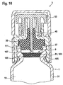
- ein fünftes Ausführungsbeispiel eines Verschlusses, und
Figur 11- das Ausführungsbeispiel gemäß 10 in aktiviertem Zustand.
- FIG. 1
- a trained as a dual chamber system powder syringe with a first embodiment of the closure;
- FIG. 2
- a detailed view of the embodiment of a closure according to
FIG. 1 ; - FIG. 3
- a second embodiment of a closure;
- FIG. 4
- a sectional view of the embodiment according to
FIG. 3 along the line AA; - FIG. 5
- a third embodiment of a closure;
- FIG. 6
- one in terms of
FIG. 5 slightly modified embodiment of a closure on a powder syringe in the activated state; - FIG. 7
- a sectional view of the embodiment according to
FIG. 6 along the line AA; - FIG. 8
- a fourth embodiment of a closure;
- FIG. 9
- the embodiment according to
FIG. 8 in activated state; - FIG. 10
- a fifth embodiment of a closure, and
- FIG. 11
- the embodiment of FIG. 10 in the activated state.
Bei dem dargstellten Ausführungsbeispiel ist die Pulverspritze 1 als Doppelkammersystem ausgebildet. Bei dessen Herstellung wird bevorzugt durch die proximale Öffnung 11 ein Mittelstopfen 15 in das Innere der Pulverspritze 1 eingeführt, welcher eine proximale Kammer 17 von einer distalen Kammer 19 trennt. Die distale Kammer 19 wird bevorzugt durch die distale Öffnung 9 befüllt. Beispielsweise kann hier ein gelöster Wirkstoff oder eine Kombination gelöster Wirkstoffe, allgemein also eine Lösung eingefüllt werden, welche anschließend lyophilisiert wird. Danach wird die distale Kammer 19 beziehungsweise die distale Öffnung 9 durch den Verschluss 3 verschlossen. Ein in der distalen Kammer 19 angeordneter LyophilisatKuchen haftet typischerweise an einer Wandung 21 der Pulverspritze 1, so dass er nicht frei in der distalen Kammer 19 beweglich ist.In the dargstellten embodiment, the
Wird stattdessen eine pulverförmige, lösliche Substanz in die distale Kammer 19 gefüllt, kann diese sich dort frei verteilen. Die distale Kammer 19 wird mit dem Verschluss 3 verschlossen. Das Pulver kann dann in den Bereich eines Kanals des Verschlusses 3 gelangen und dort gegebenenfalls unlösliche Agglomerate bilden. Diese verstopfen den Kanal und beeinträchtigen die Funktionsfähigkeit der Pulverspritze 1.If, instead, a pulverulent, soluble substance is filled into the
Durch die proximale Öffnung 11 kann in die proximale Kammer 17 ein Lösungsmittel eingefüllt werden, wonach diese durch einen Endstopfen 23 verschlossen wird. Der Endstopfen 23 weist bevorzugt Kopplungsmittel 25 zur Kopplung mit einer nichtdargestellten Kolbenstange auf. Bei dem dargestellten Ausführungsbeispiel ist das Kopplungsmittel 25 ein Innengewinde, welches mit einem an der nicht dargestellten Kolbenstange vorgesehenen Außengewinde kämmen kann.Through the
Bevorzugt liegt also in der distalen Kammer 19 der hier als Doppelkammersystem ausgebildeten Pulverspritze 1 ein Pulver 27 vor. In der proximalen Kammer 17 liegt bevorzugt ein Lösungsmittel 29 vor. Das Pulver 27 ist bevorzugt in dem Lösungsmittel 29 löslich.Preferably, therefore, a
Die Wandung 21 weist im Bereich der distalen Kammer 19 einen radialen Vorsprung auf, der sich - in Umfangsrichtung gesehen - nur über einen relativ kleinen Winkelbereich erstreckt und als Bypass 31 ausgebildet ist. Zur Aktivierung des Doppelkammersystems wird der Endstopfen 23 mit Hilfe der hier nicht dargestellten Kolbenstange in Richtung des distalen Endes 7 verlagert, wobei sich aufgrund der in der proximalen Kammer 17 ausgebildeten Druckkräfte auch der Mittelstopfen 15 in diese Richtung verlagert.In the region of the
In der vorliegenden Beschreibung wird allgemein Bezug genommen auf eine Längsrichtung, welche der Längserstreckung der Pulverspritze 1 entspricht. Eine radiale Richtung ist entsprechend eine Richtung, die auf der Längsrichtung senkrecht steht. Die Längsrichtung wird auch als axiale Richtung angesprochen. Eine Umfangsrichtung erstreckt sich entlang einer Umfangslinie um die Längsachse der Pulverspritze 1.In the present description, reference is generally made to a longitudinal direction which corresponds to the longitudinal extent of the
Der Bypass 31 weist - in Längsrichtung gesehen - eine Erstreckung auf, die größer ist als die axiale Länge des Mittelstopfens 15. Wird daher der Mittelstopfen 15 in den Bereich des Bypasses 31 verlagert, wird eine Fluidverbindung zwischen der proximalen Kammer 17 und der distalen Kammer 19 über den Bypass 31 ausgebildet. Das Lösungsmittel 29 wird dann insbesondere mittels einer weiteren Verlagerung des Endstopfens 23 von der proximalen Kammer 17 in die distale Kammer 19 eingebracht, wo es das Pulver 27 löst. Schließlich wird ein Zustand erreicht, in dem der Mittelstopfen 15 und der Endstopfen 23 aneinander anliegen. Durch eine Weiterverlagerung der beiden Stopfen zu dem distalen Ende 7 hin kann die nunmehr in der distalen Kammer 19 vorliegende Lösung aus der Pulverspritze 1 ausgetrieben und vorzugsweise in einen Patienten injiziert werden. Die Ausgestaltung und Funktionsweise solcher Doppelkammersysteme ist an sich bekannt, sodass hier nicht weiter darauf eingegangen wird.The
Bei Doppelkammersystemen, die in ihrer distalen Kammer Pulver aufnehmen sollen, ist die distale Öffnung 9 bevorzugt im Vergleich zu für Lyophilisate vorgesehenen Doppelkammersystemen erweitert, weil so das Pulver leichter eingefüllt werden kann, während für eine Lösung ein kleinerer Durchmesser genügt.In dual-chamber systems, which are intended to receive powder in their distal chamber, the
Die Erfindung ist nicht auf Pulverspritzen beschränkt, die als Doppelkammersysteme ausgebildet sind. Das Problem, dass in einer Kammer der Spritze vorhandenes Pulver in einem Kanal eines Verschlusses agglomerieren kann, ergibt sich grundsätzlich bei jeder Pulverspritze. Entsprechend ist auch die hier vorgeschlagene Lösung bei jeder beliebigen Pulverspritze anwendbar. Es zeigt sich auch, dass es nicht ausgeschlossen ist, dass ein in einer distalen, Kammer eines Doppelkammersystems vorliegendes Lyophylisat im Laufe der Lagerung zumindest teilweise pulverförmig wird und dann den Kanal eines Verschlusses verstopfen kann. Der hier vorgeschlagene Verschluss kann daher selbstverständlich bevorzugt auch bei einem Doppelkammersystem verwendet werden, welches in seiner distalen Kammer ein Lyophilisat umfasst.The invention is not limited to powder spraying, which are designed as a double-chamber systems. The problem that powder present in a chamber of the syringe can agglomerate in a channel of a closure generally results with every powder syringe. Accordingly, the solution proposed here is applicable to any powder syringe. It also turns out that it is not excluded that a lyophilisate present in a distal chamber of a dual-chamber system becomes at least partially powdered during storage and can then clog the channel of a closure. The closure proposed here can therefore of course also preferably be used in a dual-chamber system which comprises a lyophilisate in its distal chamber.
Das Dichtelement 35 besteht aus einem elastischen Material und ist quasi zwischen der Wandung 21 der Pulverspritze 1 und dem Grundkörper 33 des Verschlusses 3 eingeklemmt, sodass sich eine Dichtwirkung ergibt. Dabei weist bei dem dargestellten Ausführungsbeispiel ein Mündungsbereich 37 der Pulverspritze 1 eine Innenkontur auf, an die eine Außenkontur des Dichtelements 35 angepasst ist, sodass dieses in der Verschließposition des Verschlusses 3 entlang des gesamten Mündungsbereichs 37 dichtend anliegt.The sealing
In
Der Grundkörper 33 weist an seinem der distalen Kammer 19 zugewandten Ende nach innen weisende, radiale Vorsprünge 39, 39' auf. Mit diesen hintergreift er einen Flansch 41 der Pulverspritze 1, der im Mündungsbereich 37 so vorgesehen ist, dass in der Wandung 21 quasi eine Hinterschneidung oder Nut 43 ausgebildet ist. In diese greifen die Vorsprünge 39, 39' in der Verschließposition des Verschlusses 3 quasi als Rastnasen ein. So ist es möglich, in das Dichtelement 35 Kräfte einzuleiten, die es zusammenpressen und seine dichte Anlage im Bereich der distalen Öffnung 9 beziehungsweise im Mündungsbereich 37 ermöglichen. Zugleich wird der Verschluss 3 durch die Vorsprünge 39, 39' sicher auf dem durch die Wandung 21 gebildeten Grundkörper der Pulverspritze 1 gehalten.The
Wird der Verschluss 3 in Zusammenhang mit einem in der distalen Kammer 19 vorgesehenen Lyophilisat verwendet, umfasst bevorzugt der Flansch 41 eine ringförmige Nut, die ihn - in Umfangsrichtung gesehen - umgreift. Auch in diese hier nicht dargestellte Nut können die Vorsprünge 39, 39' verrastend eingreifen. In der Ansicht von Figur 2 ist dann quasi über der dargestellten Rastposition des Verschlusses 3 eine weitere Rastposition ausgebildet, in welcher das Dichtelement 35 nicht nur nicht komprimiert ist, sondern einen Spalt im Bereich der distalen Öffnung 9 freilässt, sodass eine Fluidverbindung von der distalen Kammer 19 in den Umgebungsbereich der Pulverspritze 1 besteht. Es ist möglich, eine in der distalen Kammer 19 vorgelegte Lösung zu lyophilisieren, während der Verschluss 3 in seiner oberen Rastposition angeordnet ist. Nach Abschluss des Lyophilisationsvorgangs wird der Verschluss 3 dann in seine in
Der Verschluss 3 weist einen Kanal 45 auf, welcher den Grundkörper 33 und das Dichtelement 35 durchsetzt. Der Kanal 45 weist ein proximales Ende 47 und ein distales Ende 49 auf.The
Bei bekannten Verschlüssen ist es möglich, dass pulverförmiges Material aus der distalen Kammer 19 über das proximale Ende 47 in den Kanal 45 eindringen kann. Dort können sich Agglomerate bilden, die gegebenenfalls unlöslich sind und die Funktionsfähigkeit der Pulverspritze 1 beeinträchtigen.In known closures, it is possible that powdered material from the
Um dies zu vermeiden, weist der Verschluss 3 ein Rückhalteelement 51 auf, das so ausgebildet und/oder anordenbar ist, dass jedenfalls vor einer Aktivierung der Pulverspritze vorzugsweise kein Pulver aus der distalen Kammer 19 in den Kanal 45 eindringen kann, wenn der Verschluss 3 in seiner in
Bei dem dargestellten Ausführungsbeispiel weist der Verschluss 3 eine Verschlusskappe 53 auf, die das distale Ende 49 des Kanals 45 verschließt.In the illustrated embodiment, the
Die Verschlusskappe 53 umfasst einen vorzugsweise stabförmigen Vorsprung 55. Dieser durchsetzt den Kanal. Das Rückhalteelement 51 ist an dem Vorsprung 55 vorgesehen.The
Beispielsweise ist es möglich, den vorzugsweise stabförmigen Vorsprung 55 mit einem Durchmesser auszubilden, der größer ist als der Durchmesser des das Dichtelement 35 durchsetzenden Abschnitts des Kanals 45. Das Dichtelement 35 wird dann komprimiert, wenn der Vorsprung 55 in den entsprechenden Kanalabschnitt eingeführt wird, und es liegt dementsprechend dichtend an demselben an. Weist der Vorsprung 55 dann - in Längsrichtung gesehen - eine Erstreckung auf, die bis zum proximalen Ende 47 reicht, ist der Kanal 45 dicht verschlossen, sodass kein Pulver in ihn eindringen kann.For example, it is possible to form the preferably rod-shaped
Nachteilig an einem Ausführungsbeispiel, bei dem der stabförmige Vorsprung 55 entlang seiner gesamten Längserstreckung einen entsprechenden Durchmesser aufweist ist allerdings, dass zur Entfernung der Verschlusskappe 53 große Kräfte aufgrund der Reibung zwischen dem Vorsprung 55 und dem Dichtelement 35 nötig sind.A disadvantage of an embodiment in which the rod-shaped
Es wird daher ein Ausführungsbeispiel bevorzugt, bei dem das Rückhalteelement 51 als Verdickung 57 des stabförmigen Vorsprungs ausgebildet ist. Bei dem dargestellten, bevorzugten Ausführungsbeispiel ist die Verdickung 57 an einem der distalen Kammer 19 zugewandten Ende des Vorsprungs 55 vorgesehen. Bevorzugt durchgreift der Vorsprung 55 das gesamte Dichtelement 35, sodass er mit der Verdickung 57 zumindest bereichsweise aus dem proximalen Ende 47 des Kanals 45 herausragt. Im Bereich der Verdickung 57, die vorzugsweise einen größten Durchmesser aufweist, der größer ist als der Innendurchmesser des in dem Dichtelement 35 vorgesehenen Abschnitts des Kanals 45, liegt das Dichtelement 35 dichtend an, sodass das proximale Ende 47 dicht verschlossen ist. Es kann also kein Pulver in den Kanal 45 eindringen.An embodiment is therefore preferred in which the retaining
Ist ein Rückhalteelement in Form der Verdickung 57 an dem Vorsprung 55 vorgesehen, kann dessen Durchmesser außerhalb der Verdickung 57 kleiner ausgebildet sein, als es dem Innendurchmesser des Abschnitts des Kanals 45 in dem Dichtelement 35 entspricht. Hierdurch werden Reibungskräfte beim Entfernen der Verschlusskappe 53 reduziert.If a retaining element in the form of the thickening 57 is provided on the
Es ist möglich, den Durchmesser des Vorsprungs 55 in dem Bereich, in dem dieser dem proximalen Ende 47 gegenüberliegend aus dem Dichtelement 35 austritt, größer zu gestalten, um auch hier den Abschnitt des Kanals 45, der sich durch das Dichtelement 35 erstreckt, dicht zu verschließen. In diesem Fall ist dann der Eintritt und der Austritt des Kanals 45 in das Dichtelement 35 beziehungsweise aus diesem heraus durch den Vorsprung 55 dicht verschlossen. Anhand von
Bei dem dargestellten Ausführungsbeispiel ist das Dichtelement 35 - in axialer Richtung gesehen - kürzer ausgebildet als bei dem Ausführungsbeispiel gemäß
Das Dichtelement 35 erstreckt sich bei dem dargestellten Ausführungsbeispiel allerdings durch den gesamten Ansatz 59 des Grundkörpers 33. Es übergreift sogar - in axialer Richtung gesehen - den Ansatz 59 und bildet an dessen distalem Ende einen ringförmigen Auflagebereich 71.The sealing
Die Verschlusskappe 53 liegt hier mit dem Wandabschnitt 63 dichtend an dem Ansatz 59 an. Sie weist nur einen kurzen zentralen Vorsprung 73 auf, der vergleichweise nur über eine kurze Distanz in den Kanal 45 hineinragt und dicht an dem Dichtelement 35 anliegt.The
Das Material, welches der Grundkörper 33 und damit auch der Ansatz 59 umfasst, beziehungsweise aus welchem diese bestehen, ist typischerweise nicht für einen Primärkontakt geeignet. Dies bedeutet, dass ein Medikament insbesondere während seiner Lagerung keinen Kontakt zu dem Grundkörper 33 haben darf. Daher weist typischerweise die Verschlusskappe 53 einen Vorsprung 73 auf, der sich - in axialer Richtung gesehen - zumindest so weit erstreckt, dass er mit dem Dichtelement 35 dichtend abschließt. Hierdurch wird vermieden, dass ein in der distalen Kammer 19 vorgesehener Wirkstoff Kontakt zu dem Material des Grundkörpers 33 bekommt. Erstreckt sich das Dichtelement 35 aber - wie bei dem in
Es zeigt sich auch noch Folgendes: Die Vorsprünge 39, 39' werden in der Verschließposition des Verschlusses 3 durch eine Sicherungskappe 75 in ihre Rastposition in der Nut 43 gedrängt. Der Sicherungsring 75 ist über Abreißstege 77 mit einer Sicherungskappe 79 verbunden, welche die Verschlusskappe 53 über- und umgreift. Beim Aufsetzen des Verschlusses 53 wird zunächst der Grundkörper 33 in seine Verschließposition verlagert, anschließend wird der Sicherungsring 75 mit der Sicherungskappe 79 über denselben geschoben, sodass der Grundkörper 33 letztlich sicher in seiner verrasteten Position gehalten wird. Um den Verschluss 3 zu öffnen, wird die Sicherungskappe 79 im Bereich der Abreißstege 77 von dem Sicherungsring 75 getrennt und entfernt. Anschließend kann die Verschlusskappe 53 entfernt werden, um eine Fluidverbindung der Umgebung der Pulverspritze 1 mit dem Kanal 45 herzustellen.It also shows the following: The
Im Zentrum der Darstellungen von
Wesentlich ist, dass eine Breite der Schlitze beziehungsweise eine im Zentrum der hier kreuzförmig angeordneten Schlitze 83, 83' angeordnete Öffnung kleiner ist als eine mittlere Korngröße des Pulvers, welches in der distalen Kammer 19 vorgesehen ist. Bevorzugt ist die Öffnung beziehungsweise die Schlitzbreite kleiner als die kleinste Korngröße dieses Pulvers. Auf diese Weise ist gewährleistet, dass die Membran 67 als Rückhaltemittel 51 wirkt und effizient verhindert, dass Pulver in den Kanal 45 eindringen kann. Wird die Pulverspritze aktiviert, soll also eine dann in der distalen Kammer 19 vorliegende Lösung injiziert werden, wird die Membran 67 aufgrund der dann in der distalen Kammer 19 aufgebauten Druckkräfte aufgeweitet und gibt zumindest im Bereich der Schlitze 83, 83' einen Fluidpfad zum Kanal 45 frei. Es ist auch möglich, dass die Membran 67 unter Einwirkung der Druckkräfte, vorzugsweise entlang der Schlitze 83, 83' aufreißt, sodass ein Fluidpfad mit größerem Durchmesser freigegeben wird.It is essential that a width of the slots or an opening arranged in the center of the
Bei dem dargestellten Ausführungsbeispiel ist die Membran 67 einstückig mit dem Dichtelement 35 ausgebildet. Es ist auch möglich, sie als separates Element vorzusehen. In diesem Fall ist sie bevorzugt in geeigneter Weise mit dem Dichtelement 35 verbunden. Besonders bevorzugt ist die Membran 67 an dem proximalen Ende 47 des Kanals 49 angeordnet.In the illustrated embodiment, the membrane 67 is formed integrally with the sealing
Bei anderen Ausführungsbeispielen kann das verlagerbare Element eine abweichende Geometrie aufweisen. Beispielsweise ist mindestens ein Vorsprung an der Kugel 85 möglich, der sich über das proximale Ende 47 hinaus in die distale Kammer 19 erstreckt. Auf diese Weise ist der Kanal 45 auch unmittelbar an seinem proximalen Ende 47 verschließbar. Statt der Kugel 85 kann beispielsweise auch ein zylindrisches Element vorgesehen sein. Auch dieses kann einen entsprechenden Vorsprung aufweisen. Beliebige andere Geometrie n sind möglich.In other embodiments, the displaceable element may have a different geometry. For example, at least one projection on the ball 85 is possible, which extends beyond the
Das verlagerbare Element umfasst bevorzugt Glas oder besteht aus diesem. Es weist dann die nötige Härte auf, so dass das Dichtelemente 35 dichtend an ihm anliegen kann. Außerdem ist Glas ein für den Primärkontakt geeignetes Material.The displaceable element preferably comprises or consists of glass. It then has the necessary hardness, so that the sealing
Bei dem dargestellten Ausführungsbeispiel ist am proximalen Ende 47 ein Haltemittel 87 für das verlagerbare Element vorgesehen. Dieses verhindert, dass das verlagerbare Element in die distale Kammer 19 eindringen kann. Bei dem dargestellten Ausführungsbeispiel ist das Haltemittel 87 als radialer Vorsprung einer Wandung des Kanals 45 ausgebildet, an dem die Kugel 85 anliegt. Weist das verlagerbare Element einen Vorsprung auf, kann dieser sich durch den Bereich des Haltemittels 87 hindurch erstrecken, sodass auch dieser Bereich sicher gegen ein Eindringen von Pulver aus der distalen Kammer 19 geschützt ist. Ein Restvolumen des Kanals 45, in welchem gegebenenfalls noch Agglomeratbildung möglich ist, wird so nicht nur minimiert, sondern weitestgehend oder sogar vollständig vermieden.In the illustrated embodiment, a retaining means 87 for the displaceable element is provided at the
Werden zur Aktivierung der Pulverspritze 1 Druckkräfte in die distale Kammer 19 eingeleitet, verlagert sich das verlagerbare Element in dem Kanal 45 von der distalen Kammer 19 weg. Schließlich tritt es an dem distalen Ende 49 aus dem Kanal 45 aus.If, in order to activate the
Hierbei ist nachteilig, dass das verlagerbare Element dann entweder aus der Pulverspritze 1 ausgespült wird, wobei es schlimmstenfalls in einen Patienten injiziert werden kann, oder dass es eine Kanüle oder eine Spritzennadel verstopft beziehungsweise deren Einlass verschließt. Es ist daher bevorzugt ein Rückhaltemittel vorgesehen, welches das verlagerbare Element zurückhält und zugleich einen Fluidpfad in eine Umgebung der Pulverspritze 1 freigibt. Ein solches Rückhaltemittel kann in einem speziell angefertigten Kanülenaufsatz vorgesehen sein. Dies ist allerdings eine vergleichsweise aufwendige und kostenintensive Lösung, weil dann der Verschluss 3 oder die Pulverspritze 1 nicht mit herkömmlichen Kanülen beziehungsweise Spritzennadeln verwendet werden kann.A disadvantage here is that the displaceable element is then either flushed out of the
Die Funktionsweise des Rückhaltemittels 89 wird anhand der Schnittdarstellung von
Der Ansatz 59 weist im Bereich des distalen Endes 49 radiale Vorsprünge 93, 93', 93"' auf, die so weit radial nach innen in den Kanal 45 hineinragen, dass das verlagerbare Element beziehungsweise die Kugel 85 von ihnen zurückgehalten wird. Bei dem dargestellten Ausführungsbeispiel sind - in Umfangsrichtung gesehen - drei radiale Vorsprünge 93, 93', 93" vorgesehen. Letztlich ist ein radialer Vorsprung ausreichend, wenn er sich radial weit genug nach innen erstreckt, um die Kugel 85 zurückzuhalten. Es sind auch zwei oder mehr als drei Vorsprünge möglich. Wesentlich ist, dass - in Umfangsrichtung gesehen - Freiräume 95, 95', 95" bestehen bleiben, die eine Fluidverbindung zwischen dem Kanal 45 und einer Umgebung der Pulverspritze 1 beziehungsweise der Kanüle 91 ermöglichen. Eine Injektionslösung kann also die Kugel 85 beziehungsweise das verlagerbare Element umströmen und durch die Freiräume 95, 95', 95" aus dem Kanal 45 aus und in den Umgebungsbereich der Pulverspritze 1 beziehungsweise in die Kanüle 91 eintreten.The
Bei dem dargestellten, bevorzugten Ausführungsbeispiel ist im Bereich des proximalen Endes 47 eine Erweiterung 99 zur Aufnahme der Substanz 97 vorgesehen. Diese bildet hier quasi einen Pfropfen, der den Kanal 45 verschließt und bewirkt, dass in der distalen Kammer 19 vorliegendes Pulver nicht in denselben eindringen kann.In the illustrated preferred embodiment, an
Die Funktionsweise dieses Ausführungsbeispiels wird anhand von
Es ist möglich, dass die Substanz 97 Hilfsstoffe wie beispielsweise Vitamin C umfasst. Zusätzlich zu dem gegebenenfalls in der distalen Kammer 19 vorliegenden Wirkstoff können also quasi mithilfe der als Rückhalteelement 51 vorgesehenen Substanz 97 zusätzliche Hilfssubstanzen zugeben werden.It is possible that the
Die Substanz 97 kann auch vorzugsweise als Pellet in das Dichtelement 35, bevorzugt in die Erweiterung 99 eingebracht werden. In diesem Fall kann der zusätzlich Lyophilisierungsschritt für die Substanz 97 entfallen.The
In
Die Pulverspritze 1 umfasst in dem Mündungsbereich 37 vorzugsweise eine Verengung 105. Die Wandung 21 springt in diesem Bereich radial nach innen, sodass die Verengung 105 gebildet wird. Bevorzugt ist die Verschlussscheibe 103 so ausgebildet, dass sie an der Verengung 105 dichtend anliegen kann. Hierzu weist sie vorzugsweise einen sich - in Umfangsrichtung gesehen - erstreckenden, radialen Vorsprung 107 auf. In einem sich - in axialer Richtung gesehen - an den Vorsprung 107 anschließenden Bereich 109 weist die Verschlussscheibe 103 bevorzugt einen Außendurchmesser auf, welcher dem Innendurchmesser der Verengung 105 entspricht. Damit folgt die Außenkontur der Verschlussscheibe 103 quasi der Innenkontur der Verengung 105 beziehungsweise des Mündungsbereichs 37, sodass sie mit dem Vorsprung 107 und dem Bereich 109 dichtend an der Wandung 21 anliegt.The
Auch bei dem dargestellten Ausführungsbeispiel umfasst die Verschlusskappe 53 vorzugsweise einen stabförmigen Vorsprung, der hier als Sicherungsstift 111 ausgebildet ist und den Kanal 45 durchsetzt. Dieser liegt bei aufgesetzter Verschlusskappe 53 in der Verschließposition des Verschlusses 3 an der Verschlussscheibe 103 an und hält diese in dichtender Anlage an der Verengung 105.Also in the illustrated embodiment, the
Die Verengung 105 ist bevorzugt im Bereich des distalen Endes 9 der Pulverspritze 1 vorgesehen.The
Die Verschlussscheibe 103 umfasst bevorzugt Gummi oder TPE, besonders bevorzugt besteht sie aus mindestens einem dieser Materialien. Sie hat dann sehr gute Dichtungseigenschaften, außerdem sind die genannten Materialien für den Primärkontakt geeignet.The closure disc 103 preferably comprises rubber or TPE, more preferably it consists of at least one of these materials. It then has very good sealing properties, in addition, the materials mentioned are suitable for primary contact.
Insgesamt zeigt sich, dass der hier vorgeschlagene Verschluss und die hier vorgeschlagene Pulverspritze mit Hilfe des Rückhalteelements 51 die Gefahr einer Agglomeratbildung in dem Kanal 45 vermeisen Dies trägt erheblich dazu bei, die Lagerfähigkeit insbesondere von als Doppelkammersystemen ausgebildeten Pulverspritzen zu verbessern und deren Funktionsfähigkeit auch bei langer Lagerung sicher zu gewährleisten.Overall, it turns out that the closure proposed here and the powder syringe proposed here with the aid of the retaining
Claims (15)
- A closure piece for a powder syringe (1) with- a main body (33),- a sealing element (35), which is disposed on the main body (33) in such a manner that it rests in a sealing manner against a distal opening (9) of a powder syringe (1), when the closure piece (3) is disposed on the powder syringe (1) in the closing position thereof, and- a channel (45), which passes through the main body (33) and the sealing element (35) and has a proximal and a distal end (47,49), and with- a retaining element (51) which is configured and/or can be disposed such that, prior to an activation of the powder syringe (1), penetration of powder (27), which comes from a chamber (19) of the powder syringe, into the channel (45) is prevented to a large extent when the closure piece (3) is disposed in its closing position on the powder syringe (1),
characterized in that- the closure piece (3) includes a closing piece cap (53) for closing the distal end (49) of the channel (45),- the closing piece cap (53) comprises a projection (55) that passes through the channel (45) and on which the retaining element (51) is provided, and that- the retaining element (51) is configured as a thickening (57) of the projection (55). - Closure piece according to claim 1, characterized in that the retaining element (51) is preferably configured as a slotted membrane (67).
- Closure piece according to claim 2, characterized in that the membrane (67) is configured in one piece with the sealing element (35) and is preferably disposed on the proximal end (47) of the channel (45).
- Closure piece according to any one of the preceding claims, characterized in that the retaining element (51) comprises an element, preferably a ball (85), that can be displaced along the channel (45) by which the proximal end (47) of the channel (45) can be closed.
- Closure piece according to claim 4, characterized in that a holding means (87) for the displaceable element is provided at the proximal end (47) of the channel (45).
- Closure piece according to any one of claims 4 or 5, characterized in that a retaining means (89) for the displaceable element is provided in the area of the distal end (49) of the channel (45).
- Closure piece according to one of the preceding claims, characterized in that the retaining element (51) comprises a soluble, preferably lyophilized substance (97).
- Closure piece according to claim 7, characterized in that an extension (99) is provided in the area of the proximal end (47) of the channel (45) for receiving the soluble substance (97).
- Closure piece according to any one of the preceding claims, characterized in that the retaining element (51) comprises a closure piece disc (103) configured such that it is able to rest in a sealing manner against a narrowing (105) of a powder syringe (1) to prevent powder (27) from penetrating into the channel (45).
- Closure piece according to claim 9, characterized in that the closure piece disc (103) includes - seen in the circumferential direction - a radially extending protrusion (107).
- Closure piece according to one of claims 9 or 10, characterized in that the closure piece disc (103) has at least one protrusion (115) on a surface (113) that is oriented toward the sealing element (35).
- Closure piece according to one of claims 9 to 11, characterized in that the closure piece cap (53) includes a rod-like projection that passes through the channel and holds the closure piece disc (103) in a sealing contact with the powder syringe (1), when the closure piece (3) is in the closing position.
- A powder syringe having a distal opening (9), characterized by a closure piece (3) according to any one of the claims 1 to 12.
- Powder syringe according to claim 13, characterized in that the powder syringe (1) is configured as a dual chamber system.
- Powder syringe according to one of claims 13 or 14, characterized in that the powder syringe (1) includes a narrowing (105) in the area of the distal end (9).
Priority Applications (2)
| Application Number | Priority Date | Filing Date | Title |
|---|---|---|---|
| EP15150520.3A EP2893915A1 (en) | 2011-03-03 | 2012-02-23 | Closure piece for a powder syringe, and powder syringe |
| EP15150522.9A EP2893946B1 (en) | 2011-03-03 | 2012-02-23 | Closure piece for a powder syringe, and powder syringe |
Applications Claiming Priority (2)
| Application Number | Priority Date | Filing Date | Title |
|---|---|---|---|
| DE201110013792 DE102011013792A1 (en) | 2011-03-03 | 2011-03-03 | Closure for a powder syringe and powder syringe |
| PCT/EP2012/000787 WO2012116792A1 (en) | 2011-03-03 | 2012-02-23 | Closure piece for a powder syringe, and powder syringe |
Related Child Applications (4)
| Application Number | Title | Priority Date | Filing Date |
|---|---|---|---|
| EP15150522.9A Division-Into EP2893946B1 (en) | 2011-03-03 | 2012-02-23 | Closure piece for a powder syringe, and powder syringe |
| EP15150522.9A Division EP2893946B1 (en) | 2011-03-03 | 2012-02-23 | Closure piece for a powder syringe, and powder syringe |
| EP15150520.3A Division-Into EP2893915A1 (en) | 2011-03-03 | 2012-02-23 | Closure piece for a powder syringe, and powder syringe |
| EP15150520.3A Division EP2893915A1 (en) | 2011-03-03 | 2012-02-23 | Closure piece for a powder syringe, and powder syringe |
Publications (2)
| Publication Number | Publication Date |
|---|---|
| EP2680907A1 EP2680907A1 (en) | 2014-01-08 |
| EP2680907B1 true EP2680907B1 (en) | 2016-02-17 |
Family
ID=45808729
Family Applications (3)
| Application Number | Title | Priority Date | Filing Date |
|---|---|---|---|
| EP15150520.3A Withdrawn EP2893915A1 (en) | 2011-03-03 | 2012-02-23 | Closure piece for a powder syringe, and powder syringe |
| EP12707475.5A Active EP2680907B1 (en) | 2011-03-03 | 2012-02-23 | Closure piece for a powder syringe, and powder syringe |
| EP15150522.9A Active EP2893946B1 (en) | 2011-03-03 | 2012-02-23 | Closure piece for a powder syringe, and powder syringe |
Family Applications Before (1)
| Application Number | Title | Priority Date | Filing Date |
|---|---|---|---|
| EP15150520.3A Withdrawn EP2893915A1 (en) | 2011-03-03 | 2012-02-23 | Closure piece for a powder syringe, and powder syringe |
Family Applications After (1)
| Application Number | Title | Priority Date | Filing Date |
|---|---|---|---|
| EP15150522.9A Active EP2893946B1 (en) | 2011-03-03 | 2012-02-23 | Closure piece for a powder syringe, and powder syringe |
Country Status (11)
| Country | Link |
|---|---|
| US (2) | US9943648B2 (en) |
| EP (3) | EP2893915A1 (en) |
| JP (1) | JP6182073B2 (en) |
| BR (1) | BR112013022566B1 (en) |
| CA (2) | CA2828906C (en) |
| DE (1) | DE102011013792A1 (en) |
| ES (2) | ES2566104T3 (en) |
| MX (1) | MX337219B (en) |
| PT (1) | PT2893946T (en) |
| RU (1) | RU2579626C2 (en) |
| WO (1) | WO2012116792A1 (en) |
Families Citing this family (14)
| Publication number | Priority date | Publication date | Assignee | Title |
|---|---|---|---|---|
| DE102012022008A1 (en) * | 2012-11-09 | 2014-05-15 | Vetter Pharma-Fertigung GmbH & Co. KG | syringe closure |
| WO2014179143A1 (en) * | 2013-04-29 | 2014-11-06 | 3M Innovative Properties Company | A syringe for dispensing a medicament |
| BR112016002508A2 (en) | 2013-08-07 | 2017-08-01 | Unitract Syringe Pty Ltd | luer connection adapters for retractable needle syringes |
| SG11201600884RA (en) * | 2013-08-07 | 2016-03-30 | Unitract Syringe Pty Ltd | Luer connection adapters for syringes |
| WO2019088136A1 (en) * | 2017-10-31 | 2019-05-09 | テルモ株式会社 | Syringe and prefilled syringe |
| USD862694S1 (en) | 2017-11-08 | 2019-10-08 | Schott Kaisha Pvt. Ltd | Syringe cap for sealing syringe for medical purpose |
| CN107929881B (en) * | 2017-12-25 | 2023-08-25 | 江南大学 | Integrated structure of preparation injector |
| CN112368044B (en) * | 2018-06-20 | 2023-02-10 | 费森尤斯卡比德国有限公司 | Connector assembly for connecting a medical line comprising a cover element |
| DE102018210941A1 (en) * | 2018-07-03 | 2020-01-09 | Vetter Pharma-Fertigung GmbH & Co. KG | Stopper device, medication container and method for mixing two substances in a medication container |
| US11154663B2 (en) * | 2018-10-25 | 2021-10-26 | Sharps Technology Inc. | Pre-filled safety needle and syringe system |
| US11911588B2 (en) | 2019-08-06 | 2024-02-27 | Microvention, Inc. | Syringe |
| KR20230038187A (en) | 2020-06-09 | 2023-03-17 | 벡티브바이오 에이지 | Manufacture, Formulation and Administration of Afraglutide |
| JP2022012330A (en) * | 2020-07-01 | 2022-01-17 | テルモ株式会社 | Prefilled syringe, syringe assembly, method for manufacturing prefilled syringe and method for increasing surface area |
| DE102021127437A1 (en) | 2021-10-21 | 2023-04-27 | Vetter Pharma-Fertigung GmbH & Co. KG | Closure for a medical hollow body, medical hollow body with such a closure and method for producing such a closure |
Family Cites Families (27)
| Publication number | Priority date | Publication date | Assignee | Title |
|---|---|---|---|---|
| GB576720A (en) * | 1942-06-17 | 1946-04-17 | Squibb & Sons Inc | Sterilization |
| US3380449A (en) | 1964-11-02 | 1968-04-30 | Stanley J. Sarnoff | Cartridge with burstable seal |
| US4059109A (en) | 1976-07-27 | 1977-11-22 | Tischlinger Edward A | Mixing and dispensing disposable medicament injector |
| US4331146A (en) * | 1976-12-23 | 1982-05-25 | The West Company | Syringe assembly |
| EP0072057B1 (en) | 1981-08-10 | 1988-02-10 | Duphar International Research B.V | Automatic injection syringe |
| US4479801A (en) * | 1982-06-25 | 1984-10-30 | Cohen Milton J | Fluid dispensing device |
| DE3916101A1 (en) * | 1989-05-17 | 1990-11-22 | Vetter & Co Apotheker | SYRINGE FOR MEDICAL PURPOSES |
| DE4127650C1 (en) * | 1991-08-21 | 1993-02-25 | Arzneimittel Gmbh Apotheker Vetter & Co Ravensburg, 7980 Ravensburg, De | |
| AU694124B2 (en) * | 1994-06-16 | 1998-07-16 | Kwik Kork International Inc | Cork stopper for bottles of wine |
| NL9401173A (en) | 1994-07-15 | 1996-02-01 | A P I S Medical Bv | Pre-filled syringe assembly. |
| AUPM922394A0 (en) * | 1994-11-03 | 1994-11-24 | Astra Pharmaceuticals Pty Ltd | Plastic syringe with overcap |
| US6196998B1 (en) * | 1994-12-12 | 2001-03-06 | Becton Dickinson And Company | Syringe and tip cap assembly |
| US5779668A (en) * | 1995-03-29 | 1998-07-14 | Abbott Laboratories | Syringe barrel for lyophilization, reconstitution and administration |
| JPH0910281A (en) | 1995-06-28 | 1997-01-14 | Maeda Sangyo Kk | Mouth part structure for medicine container |
| US6383168B1 (en) | 1998-12-08 | 2002-05-07 | Bioject Medical Technologies Inc. | Needleless syringe with prefilled cartridge |
| JP3591636B2 (en) * | 2000-04-03 | 2004-11-24 | ニプロ株式会社 | Prefilled syringe |
| US6953445B2 (en) | 2000-10-10 | 2005-10-11 | Meridian Medical Technologies, Inc. | Wet/dry automatic injector assembly |
| US6666852B2 (en) * | 2000-12-04 | 2003-12-23 | Bracco Diagnostics, Inc. | Axially activated vial access adapter |
| KR20040096561A (en) * | 2002-02-15 | 2004-11-16 | 앤태어스 파머, 인코퍼레이티드 | Injector with bypass channel |
| US6883222B2 (en) | 2002-10-16 | 2005-04-26 | Bioject Inc. | Drug cartridge assembly and method of manufacture |
| US20080009822A1 (en) * | 2003-12-18 | 2008-01-10 | Halkey-Roberts Corporation | Needleless access vial |
| AT500930B1 (en) | 2004-10-25 | 2007-03-15 | Pharma Consult Ges M B H & Co | METHOD AND DEVICE FOR LYOPHILIZING, RECONSTITUTING AND DISTRIBUTING A RECONSTITUTED ACTIVE SUBSTANCE |
| US20080033347A1 (en) * | 2006-08-03 | 2008-02-07 | Becton, Dickinson And Company | Detachable needle syringe having reduced dead space |
| US8002751B2 (en) * | 2006-10-23 | 2011-08-23 | Sue Carr | Filter needle |
| US8469923B2 (en) | 2007-09-27 | 2013-06-25 | Becton, Dickinson And Company | Cartridge for powder and liquid drug |
| US8574214B2 (en) * | 2008-08-30 | 2013-11-05 | Sanofi-Aventis Deutschland Gmbh | Cartridge and needle system therefor |
| JP2010131064A (en) * | 2008-12-02 | 2010-06-17 | Arte Corp | Container-cum-syringe |
-
2011
- 2011-03-03 DE DE201110013792 patent/DE102011013792A1/en not_active Ceased
-
2012
- 2012-02-23 RU RU2013144328/14A patent/RU2579626C2/en active
- 2012-02-23 CA CA2828906A patent/CA2828906C/en active Active
- 2012-02-23 CA CA3045962A patent/CA3045962C/en active Active
- 2012-02-23 EP EP15150520.3A patent/EP2893915A1/en not_active Withdrawn
- 2012-02-23 BR BR112013022566-1A patent/BR112013022566B1/en active IP Right Grant
- 2012-02-23 US US14/002,580 patent/US9943648B2/en active Active
- 2012-02-23 JP JP2013555782A patent/JP6182073B2/en active Active
- 2012-02-23 ES ES12707475.5T patent/ES2566104T3/en active Active
- 2012-02-23 EP EP12707475.5A patent/EP2680907B1/en active Active
- 2012-02-23 ES ES15150522.9T patent/ES2626565T3/en active Active
- 2012-02-23 WO PCT/EP2012/000787 patent/WO2012116792A1/en active Application Filing
- 2012-02-23 MX MX2013010102A patent/MX337219B/en active IP Right Grant
- 2012-02-23 PT PT151505229T patent/PT2893946T/en unknown
- 2012-02-23 EP EP15150522.9A patent/EP2893946B1/en active Active
-
2018
- 2018-01-09 US US15/865,350 patent/US10357611B2/en active Active
Also Published As
| Publication number | Publication date |
|---|---|
| US9943648B2 (en) | 2018-04-17 |
| CA2828906A1 (en) | 2012-09-07 |
| JP6182073B2 (en) | 2017-08-16 |
| CA3045962C (en) | 2021-12-28 |
| EP2680907A1 (en) | 2014-01-08 |
| CA3045962A1 (en) | 2012-09-07 |
| BR112013022566B1 (en) | 2021-05-11 |
| BR112013022566A2 (en) | 2016-12-06 |
| US20130338575A1 (en) | 2013-12-19 |
| EP2893946A1 (en) | 2015-07-15 |
| EP2893946B1 (en) | 2017-04-05 |
| US20180126081A1 (en) | 2018-05-10 |
| US10357611B2 (en) | 2019-07-23 |
| RU2579626C2 (en) | 2016-04-10 |
| MX337219B (en) | 2016-02-18 |
| ES2626565T3 (en) | 2017-07-25 |
| EP2893915A1 (en) | 2015-07-15 |
| PT2893946T (en) | 2017-07-18 |
| CA2828906C (en) | 2021-10-19 |
| RU2013144328A (en) | 2015-04-10 |
| JP2014508603A (en) | 2014-04-10 |
| ES2566104T3 (en) | 2016-04-11 |
| WO2012116792A1 (en) | 2012-09-07 |
| DE102011013792A1 (en) | 2012-09-06 |
| MX2013010102A (en) | 2014-01-08 |
Similar Documents
| Publication | Publication Date | Title |
|---|---|---|
| EP2680907B1 (en) | Closure piece for a powder syringe, and powder syringe | |
| EP2678054B1 (en) | Head of an injection syringe, injection assembly and injection syringe | |
| EP2252350B1 (en) | Administering apparatus comprising a blockable actuation element | |
| EP1804862B1 (en) | Method and devices for lyophilizing, reconstituting, and administering a reconstituted agent | |
| EP0401515B1 (en) | Implantable device for dispensing measured amounts of medicaments in the human body | |
| EP1186312B1 (en) | Dispensing device for substances | |
| WO2007020239A1 (en) | Twin-chamber receptacle and method for filling the same | |
| EP2588221B1 (en) | Combined mixing and discharging device | |
| WO2003008021A1 (en) | Device for distributing substances | |
| AT505616A4 (en) | INJECTION sYRINGE | |
| EP2680909A1 (en) | Closure and method for producing a closure | |
| DE10140704A1 (en) | Process for mixing a poorly soluble pharmaceutical substance with a solvent and syringe to apply the process | |
| EP1917055A2 (en) | Twin-chamber receptacle without a bypass | |
| WO2011091542A1 (en) | Device for removing a fluid from a vial | |
| DE8235862U1 (en) | INJECTION DEVICE FOR AN INFUSION OR TRANSFUSION SYSTEM | |
| CH400462A (en) | Injection syringe | |
| DE1296312B (en) | Two-chamber container for the separate filling and storage of drugs and solutions or diluents in a form suitable for later mixing and subsequent removal | |
| EP3801688A1 (en) | Device and method for dispensing at least one substance | |
| WO2004006997A1 (en) | Administration device comprising a plunger rod with a return lock | |
| WO2010085903A1 (en) | Administering device comprising a holding element for a fluid receptacle | |
| EP2953669B1 (en) | Dispensing device for dispensing a fluid | |
| WO2016055445A1 (en) | System and method for providing an injection | |
| WO2018149920A1 (en) | Medicine container for storing and providing at least two medicine substances that can be mixed with one another, and method for operating a medicine container of this type | |
| DE1491785C (en) | Injection syringe with two coaxial cylindrical chambers | |
| DE2153772A1 (en) | Medical syringe |
Legal Events
| Date | Code | Title | Description |
|---|---|---|---|
| PUAI | Public reference made under article 153(3) epc to a published international application that has entered the european phase |
Free format text: ORIGINAL CODE: 0009012 |
|
| 17P | Request for examination filed |
Effective date: 20131004 |
|
| AK | Designated contracting states |
Kind code of ref document: A1 Designated state(s): AL AT BE BG CH CY CZ DE DK EE ES FI FR GB GR HR HU IE IS IT LI LT LU LV MC MK MT NL NO PL PT RO RS SE SI SK SM TR |
|
| DAX | Request for extension of the european patent (deleted) | ||
| RIC1 | Information provided on ipc code assigned before grant |
Ipc: A61M 5/28 20060101AFI20150629BHEP Ipc: A61M 5/34 20060101ALI20150629BHEP Ipc: A61M 5/31 20060101ALN20150629BHEP |
|
| GRAP | Despatch of communication of intention to grant a patent |
Free format text: ORIGINAL CODE: EPIDOSNIGR1 |
|
| RIC1 | Information provided on ipc code assigned before grant |
Ipc: A61J 1/14 20060101ALN20150727BHEP Ipc: A61M 5/28 20060101AFI20150727BHEP Ipc: A61M 5/31 20060101ALN20150727BHEP Ipc: A61M 5/34 20060101ALI20150727BHEP |
|
| INTG | Intention to grant announced |
Effective date: 20150902 |
|
| GRAS | Grant fee paid |
Free format text: ORIGINAL CODE: EPIDOSNIGR3 |
|
| GRAA | (expected) grant |
Free format text: ORIGINAL CODE: 0009210 |
|
| RAP1 | Party data changed (applicant data changed or rights of an application transferred) |
Owner name: VETTER PHARMA-FERTIGUNG GMBH & CO. KG |
|
| AK | Designated contracting states |
Kind code of ref document: B1 Designated state(s): AL AT BE BG CH CY CZ DE DK EE ES FI FR GB GR HR HU IE IS IT LI LT LU LV MC MK MT NL NO PL PT RO RS SE SI SK SM TR |
|
| REG | Reference to a national code |
Ref country code: GB Ref legal event code: FG4D Free format text: NOT ENGLISH |
|
| REG | Reference to a national code |
Ref country code: FR Ref legal event code: PLFP Year of fee payment: 5 |
|
| REG | Reference to a national code |
Ref country code: CH Ref legal event code: EP |
|
| REG | Reference to a national code |
Ref country code: IE Ref legal event code: FG4D Free format text: LANGUAGE OF EP DOCUMENT: GERMAN |
|
| REG | Reference to a national code |
Ref country code: AT Ref legal event code: REF Ref document number: 775346 Country of ref document: AT Kind code of ref document: T Effective date: 20160315 Ref country code: CH Ref legal event code: NV Representative=s name: OFFICE ERNEST T. FREYLINGER S.A., CH |
|
| REG | Reference to a national code |
Ref country code: DE Ref legal event code: R096 Ref document number: 502012006013 Country of ref document: DE |
|
| REG | Reference to a national code |
Ref country code: ES Ref legal event code: FG2A Ref document number: 2566104 Country of ref document: ES Kind code of ref document: T3 Effective date: 20160411 |
|
| REG | Reference to a national code |
Ref country code: PT Ref legal event code: SC4A Free format text: AVAILABILITY OF NATIONAL TRANSLATION Effective date: 20160513 |
|
| REG | Reference to a national code |
Ref country code: SE Ref legal event code: TRGR |
|
| REG | Reference to a national code |
Ref country code: NL Ref legal event code: MP Effective date: 20160217 |
|
| REG | Reference to a national code |
Ref country code: LT Ref legal event code: MG4D |
|
| PG25 | Lapsed in a contracting state [announced via postgrant information from national office to epo] |
Ref country code: HR Free format text: LAPSE BECAUSE OF FAILURE TO SUBMIT A TRANSLATION OF THE DESCRIPTION OR TO PAY THE FEE WITHIN THE PRESCRIBED TIME-LIMIT Effective date: 20160217 Ref country code: NO Free format text: LAPSE BECAUSE OF FAILURE TO SUBMIT A TRANSLATION OF THE DESCRIPTION OR TO PAY THE FEE WITHIN THE PRESCRIBED TIME-LIMIT Effective date: 20160517 Ref country code: FI Free format text: LAPSE BECAUSE OF FAILURE TO SUBMIT A TRANSLATION OF THE DESCRIPTION OR TO PAY THE FEE WITHIN THE PRESCRIBED TIME-LIMIT Effective date: 20160217 |
|
| PG25 | Lapsed in a contracting state [announced via postgrant information from national office to epo] |
Ref country code: RS Free format text: LAPSE BECAUSE OF FAILURE TO SUBMIT A TRANSLATION OF THE DESCRIPTION OR TO PAY THE FEE WITHIN THE PRESCRIBED TIME-LIMIT Effective date: 20160217 Ref country code: NL Free format text: LAPSE BECAUSE OF FAILURE TO SUBMIT A TRANSLATION OF THE DESCRIPTION OR TO PAY THE FEE WITHIN THE PRESCRIBED TIME-LIMIT Effective date: 20160217 Ref country code: LV Free format text: LAPSE BECAUSE OF FAILURE TO SUBMIT A TRANSLATION OF THE DESCRIPTION OR TO PAY THE FEE WITHIN THE PRESCRIBED TIME-LIMIT Effective date: 20160217 Ref country code: PL Free format text: LAPSE BECAUSE OF FAILURE TO SUBMIT A TRANSLATION OF THE DESCRIPTION OR TO PAY THE FEE WITHIN THE PRESCRIBED TIME-LIMIT Effective date: 20160217 Ref country code: LT Free format text: LAPSE BECAUSE OF FAILURE TO SUBMIT A TRANSLATION OF THE DESCRIPTION OR TO PAY THE FEE WITHIN THE PRESCRIBED TIME-LIMIT Effective date: 20160217 |
|
| REG | Reference to a national code |
Ref country code: GR Ref legal event code: EP Ref document number: 20160400937 Country of ref document: GR Effective date: 20160628 |
|
| PG25 | Lapsed in a contracting state [announced via postgrant information from national office to epo] |
Ref country code: EE Free format text: LAPSE BECAUSE OF FAILURE TO SUBMIT A TRANSLATION OF THE DESCRIPTION OR TO PAY THE FEE WITHIN THE PRESCRIBED TIME-LIMIT Effective date: 20160217 Ref country code: DK Free format text: LAPSE BECAUSE OF FAILURE TO SUBMIT A TRANSLATION OF THE DESCRIPTION OR TO PAY THE FEE WITHIN THE PRESCRIBED TIME-LIMIT Effective date: 20160217 |
|
| REG | Reference to a national code |
Ref country code: DE Ref legal event code: R097 Ref document number: 502012006013 Country of ref document: DE |
|
| PG25 | Lapsed in a contracting state [announced via postgrant information from national office to epo] |
Ref country code: CZ Free format text: LAPSE BECAUSE OF FAILURE TO SUBMIT A TRANSLATION OF THE DESCRIPTION OR TO PAY THE FEE WITHIN THE PRESCRIBED TIME-LIMIT Effective date: 20160217 Ref country code: SM Free format text: LAPSE BECAUSE OF FAILURE TO SUBMIT A TRANSLATION OF THE DESCRIPTION OR TO PAY THE FEE WITHIN THE PRESCRIBED TIME-LIMIT Effective date: 20160217 Ref country code: SK Free format text: LAPSE BECAUSE OF FAILURE TO SUBMIT A TRANSLATION OF THE DESCRIPTION OR TO PAY THE FEE WITHIN THE PRESCRIBED TIME-LIMIT Effective date: 20160217 Ref country code: RO Free format text: LAPSE BECAUSE OF FAILURE TO SUBMIT A TRANSLATION OF THE DESCRIPTION OR TO PAY THE FEE WITHIN THE PRESCRIBED TIME-LIMIT Effective date: 20160217 |
|
| PLBE | No opposition filed within time limit |
Free format text: ORIGINAL CODE: 0009261 |
|
| STAA | Information on the status of an ep patent application or granted ep patent |
Free format text: STATUS: NO OPPOSITION FILED WITHIN TIME LIMIT |
|
| 26N | No opposition filed |
Effective date: 20161118 |
|
| REG | Reference to a national code |
Ref country code: FR Ref legal event code: PLFP Year of fee payment: 6 |
|
| PG25 | Lapsed in a contracting state [announced via postgrant information from national office to epo] |
Ref country code: SI Free format text: LAPSE BECAUSE OF FAILURE TO SUBMIT A TRANSLATION OF THE DESCRIPTION OR TO PAY THE FEE WITHIN THE PRESCRIBED TIME-LIMIT Effective date: 20160217 Ref country code: BG Free format text: LAPSE BECAUSE OF FAILURE TO SUBMIT A TRANSLATION OF THE DESCRIPTION OR TO PAY THE FEE WITHIN THE PRESCRIBED TIME-LIMIT Effective date: 20160517 |
|
| REG | Reference to a national code |
Ref country code: NL Ref legal event code: FP |
|
| PG25 | Lapsed in a contracting state [announced via postgrant information from national office to epo] |
Ref country code: MT Free format text: LAPSE BECAUSE OF FAILURE TO SUBMIT A TRANSLATION OF THE DESCRIPTION OR TO PAY THE FEE WITHIN THE PRESCRIBED TIME-LIMIT Effective date: 20160217 |
|
| REG | Reference to a national code |
Ref country code: FR Ref legal event code: PLFP Year of fee payment: 7 |
|
| PG25 | Lapsed in a contracting state [announced via postgrant information from national office to epo] |
Ref country code: HU Free format text: LAPSE BECAUSE OF FAILURE TO SUBMIT A TRANSLATION OF THE DESCRIPTION OR TO PAY THE FEE WITHIN THE PRESCRIBED TIME-LIMIT; INVALID AB INITIO Effective date: 20120223 Ref country code: CY Free format text: LAPSE BECAUSE OF FAILURE TO SUBMIT A TRANSLATION OF THE DESCRIPTION OR TO PAY THE FEE WITHIN THE PRESCRIBED TIME-LIMIT Effective date: 20160217 |
|
| PG25 | Lapsed in a contracting state [announced via postgrant information from national office to epo] |
Ref country code: IS Free format text: LAPSE BECAUSE OF FAILURE TO SUBMIT A TRANSLATION OF THE DESCRIPTION OR TO PAY THE FEE WITHIN THE PRESCRIBED TIME-LIMIT Effective date: 20160217 Ref country code: MK Free format text: LAPSE BECAUSE OF FAILURE TO SUBMIT A TRANSLATION OF THE DESCRIPTION OR TO PAY THE FEE WITHIN THE PRESCRIBED TIME-LIMIT Effective date: 20160217 Ref country code: MC Free format text: LAPSE BECAUSE OF FAILURE TO SUBMIT A TRANSLATION OF THE DESCRIPTION OR TO PAY THE FEE WITHIN THE PRESCRIBED TIME-LIMIT Effective date: 20160217 Ref country code: TR Free format text: LAPSE BECAUSE OF FAILURE TO SUBMIT A TRANSLATION OF THE DESCRIPTION OR TO PAY THE FEE WITHIN THE PRESCRIBED TIME-LIMIT Effective date: 20160217 Ref country code: LU Free format text: LAPSE BECAUSE OF NON-PAYMENT OF DUE FEES Effective date: 20160223 |
|
| PG25 | Lapsed in a contracting state [announced via postgrant information from national office to epo] |
Ref country code: AL Free format text: LAPSE BECAUSE OF FAILURE TO SUBMIT A TRANSLATION OF THE DESCRIPTION OR TO PAY THE FEE WITHIN THE PRESCRIBED TIME-LIMIT Effective date: 20160217 |
|
| PG25 | Lapsed in a contracting state [announced via postgrant information from national office to epo] |
Ref country code: NL Free format text: LAPSE BECAUSE OF FAILURE TO SUBMIT A TRANSLATION OF THE DESCRIPTION OR TO PAY THE FEE WITHIN THE PRESCRIBED TIME-LIMIT Effective date: 20160217 |
|
| PGRI | Patent reinstated in contracting state [announced from national office to epo] |
Ref country code: NL Effective date: 20170426 |
|
| PGFP | Annual fee paid to national office [announced via postgrant information from national office to epo] |
Ref country code: NL Payment date: 20230222 Year of fee payment: 12 |
|
| PGFP | Annual fee paid to national office [announced via postgrant information from national office to epo] |
Ref country code: IE Payment date: 20230215 Year of fee payment: 12 Ref country code: FR Payment date: 20230223 Year of fee payment: 12 Ref country code: ES Payment date: 20230321 Year of fee payment: 12 Ref country code: CH Payment date: 20230307 Year of fee payment: 12 Ref country code: AT Payment date: 20230215 Year of fee payment: 12 |
|
| PGFP | Annual fee paid to national office [announced via postgrant information from national office to epo] |
Ref country code: SE Payment date: 20230222 Year of fee payment: 12 Ref country code: PT Payment date: 20230209 Year of fee payment: 12 Ref country code: IT Payment date: 20230220 Year of fee payment: 12 Ref country code: GR Payment date: 20230220 Year of fee payment: 12 Ref country code: GB Payment date: 20230214 Year of fee payment: 12 Ref country code: DE Payment date: 20230227 Year of fee payment: 12 Ref country code: BE Payment date: 20230222 Year of fee payment: 12 |
|
| P01 | Opt-out of the competence of the unified patent court (upc) registered |
Effective date: 20230504 |
|
| PGFP | Annual fee paid to national office [announced via postgrant information from national office to epo] |
Ref country code: GR Payment date: 20240221 Year of fee payment: 13 |
|
| PGFP | Annual fee paid to national office [announced via postgrant information from national office to epo] |
Ref country code: NL Payment date: 20240226 Year of fee payment: 13 Ref country code: ES Payment date: 20240308 Year of fee payment: 13 Ref country code: IE Payment date: 20240220 Year of fee payment: 13 |
|
| PGFP | Annual fee paid to national office [announced via postgrant information from national office to epo] |
Ref country code: AT Payment date: 20240220 Year of fee payment: 13 |