EP2680307B1 - Semiconductor device package and method of manufacture - Google Patents
Semiconductor device package and method of manufacture Download PDFInfo
- Publication number
- EP2680307B1 EP2680307B1 EP13173268.7A EP13173268A EP2680307B1 EP 2680307 B1 EP2680307 B1 EP 2680307B1 EP 13173268 A EP13173268 A EP 13173268A EP 2680307 B1 EP2680307 B1 EP 2680307B1
- Authority
- EP
- European Patent Office
- Prior art keywords
- strip
- lead
- package
- recess
- singulation
- Prior art date
- Legal status (The legal status is an assumption and is not a legal conclusion. Google has not performed a legal analysis and makes no representation as to the accuracy of the status listed.)
- Active
Links
Images


Classifications
-
- H—ELECTRICITY
- H01—ELECTRIC ELEMENTS
- H01L—SEMICONDUCTOR DEVICES NOT COVERED BY CLASS H10
- H01L23/00—Details of semiconductor or other solid state devices
- H01L23/48—Arrangements for conducting electric current to or from the solid state body in operation, e.g. leads, terminal arrangements ; Selection of materials therefor
- H01L23/488—Arrangements for conducting electric current to or from the solid state body in operation, e.g. leads, terminal arrangements ; Selection of materials therefor consisting of soldered or bonded constructions
- H01L23/495—Lead-frames or other flat leads
- H01L23/49537—Plurality of lead frames mounted in one device
-
- H—ELECTRICITY
- H01—ELECTRIC ELEMENTS
- H01L—SEMICONDUCTOR DEVICES NOT COVERED BY CLASS H10
- H01L23/00—Details of semiconductor or other solid state devices
- H01L23/48—Arrangements for conducting electric current to or from the solid state body in operation, e.g. leads, terminal arrangements ; Selection of materials therefor
- H01L23/488—Arrangements for conducting electric current to or from the solid state body in operation, e.g. leads, terminal arrangements ; Selection of materials therefor consisting of soldered or bonded constructions
- H01L23/495—Lead-frames or other flat leads
- H01L23/49541—Geometry of the lead-frame
-
- H—ELECTRICITY
- H01—ELECTRIC ELEMENTS
- H01L—SEMICONDUCTOR DEVICES NOT COVERED BY CLASS H10
- H01L21/00—Processes or apparatus adapted for the manufacture or treatment of semiconductor or solid state devices or of parts thereof
- H01L21/02—Manufacture or treatment of semiconductor devices or of parts thereof
- H01L21/04—Manufacture or treatment of semiconductor devices or of parts thereof the devices having at least one potential-jump barrier or surface barrier, e.g. PN junction, depletion layer or carrier concentration layer
- H01L21/48—Manufacture or treatment of parts, e.g. containers, prior to assembly of the devices, using processes not provided for in a single one of the subgroups H01L21/06 - H01L21/326
- H01L21/4814—Conductive parts
- H01L21/4821—Flat leads, e.g. lead frames with or without insulating supports
- H01L21/4842—Mechanical treatment, e.g. punching, cutting, deforming, cold welding
-
- H—ELECTRICITY
- H01—ELECTRIC ELEMENTS
- H01L—SEMICONDUCTOR DEVICES NOT COVERED BY CLASS H10
- H01L23/00—Details of semiconductor or other solid state devices
- H01L23/28—Encapsulations, e.g. encapsulating layers, coatings, e.g. for protection
- H01L23/31—Encapsulations, e.g. encapsulating layers, coatings, e.g. for protection characterised by the arrangement or shape
- H01L23/3107—Encapsulations, e.g. encapsulating layers, coatings, e.g. for protection characterised by the arrangement or shape the device being completely enclosed
- H01L23/3114—Encapsulations, e.g. encapsulating layers, coatings, e.g. for protection characterised by the arrangement or shape the device being completely enclosed the device being a chip scale package, e.g. CSP
-
- H—ELECTRICITY
- H01—ELECTRIC ELEMENTS
- H01L—SEMICONDUCTOR DEVICES NOT COVERED BY CLASS H10
- H01L23/00—Details of semiconductor or other solid state devices
- H01L23/48—Arrangements for conducting electric current to or from the solid state body in operation, e.g. leads, terminal arrangements ; Selection of materials therefor
- H01L23/488—Arrangements for conducting electric current to or from the solid state body in operation, e.g. leads, terminal arrangements ; Selection of materials therefor consisting of soldered or bonded constructions
- H01L23/495—Lead-frames or other flat leads
- H01L23/49541—Geometry of the lead-frame
- H01L23/49548—Cross section geometry
-
- H—ELECTRICITY
- H01—ELECTRIC ELEMENTS
- H01L—SEMICONDUCTOR DEVICES NOT COVERED BY CLASS H10
- H01L23/00—Details of semiconductor or other solid state devices
- H01L23/48—Arrangements for conducting electric current to or from the solid state body in operation, e.g. leads, terminal arrangements ; Selection of materials therefor
- H01L23/488—Arrangements for conducting electric current to or from the solid state body in operation, e.g. leads, terminal arrangements ; Selection of materials therefor consisting of soldered or bonded constructions
- H01L23/495—Lead-frames or other flat leads
- H01L23/49541—Geometry of the lead-frame
- H01L23/49558—Insulating layers on lead frames, e.g. bridging members
-
- H—ELECTRICITY
- H01—ELECTRIC ELEMENTS
- H01L—SEMICONDUCTOR DEVICES NOT COVERED BY CLASS H10
- H01L23/00—Details of semiconductor or other solid state devices
- H01L23/48—Arrangements for conducting electric current to or from the solid state body in operation, e.g. leads, terminal arrangements ; Selection of materials therefor
- H01L23/488—Arrangements for conducting electric current to or from the solid state body in operation, e.g. leads, terminal arrangements ; Selection of materials therefor consisting of soldered or bonded constructions
- H01L23/495—Lead-frames or other flat leads
- H01L23/49579—Lead-frames or other flat leads characterised by the materials of the lead frames or layers thereon
- H01L23/49586—Insulating layers on lead frames
-
- H—ELECTRICITY
- H01—ELECTRIC ELEMENTS
- H01L—SEMICONDUCTOR DEVICES NOT COVERED BY CLASS H10
- H01L24/00—Arrangements for connecting or disconnecting semiconductor or solid-state bodies; Methods or apparatus related thereto
- H01L24/93—Batch processes
- H01L24/95—Batch processes at chip-level, i.e. with connecting carried out on a plurality of singulated devices, i.e. on diced chips
- H01L24/97—Batch processes at chip-level, i.e. with connecting carried out on a plurality of singulated devices, i.e. on diced chips the devices being connected to a common substrate, e.g. interposer, said common substrate being separable into individual assemblies after connecting
-
- H—ELECTRICITY
- H01—ELECTRIC ELEMENTS
- H01L—SEMICONDUCTOR DEVICES NOT COVERED BY CLASS H10
- H01L23/00—Details of semiconductor or other solid state devices
- H01L23/28—Encapsulations, e.g. encapsulating layers, coatings, e.g. for protection
- H01L23/31—Encapsulations, e.g. encapsulating layers, coatings, e.g. for protection characterised by the arrangement or shape
- H01L23/3107—Encapsulations, e.g. encapsulating layers, coatings, e.g. for protection characterised by the arrangement or shape the device being completely enclosed
-
- H—ELECTRICITY
- H01—ELECTRIC ELEMENTS
- H01L—SEMICONDUCTOR DEVICES NOT COVERED BY CLASS H10
- H01L2924/00—Indexing scheme for arrangements or methods for connecting or disconnecting semiconductor or solid-state bodies as covered by H01L24/00
- H01L2924/15—Details of package parts other than the semiconductor or other solid state devices to be connected
- H01L2924/181—Encapsulation
-
- Y—GENERAL TAGGING OF NEW TECHNOLOGICAL DEVELOPMENTS; GENERAL TAGGING OF CROSS-SECTIONAL TECHNOLOGIES SPANNING OVER SEVERAL SECTIONS OF THE IPC; TECHNICAL SUBJECTS COVERED BY FORMER USPC CROSS-REFERENCE ART COLLECTIONS [XRACs] AND DIGESTS
- Y10—TECHNICAL SUBJECTS COVERED BY FORMER USPC
- Y10T—TECHNICAL SUBJECTS COVERED BY FORMER US CLASSIFICATION
- Y10T29/00—Metal working
- Y10T29/49—Method of mechanical manufacture
- Y10T29/49002—Electrical device making
- Y10T29/49117—Conductor or circuit manufacturing
- Y10T29/49121—Beam lead frame or beam lead device
Description
- This invention relates generally to semiconductor device packages, and more specifically to leads of flat-pack no-lead semiconductor device packages.
- A semiconductor device may be mounted on a lead frame and encapsulated in a semiconductor device package (hereinafter "package"). A package utilizes leads for externally providing and receiving signals and power. One type of package is a flat-pack no-lead package where the leads are exposed at a bottom and at a side of the package.
- A lead frame strip (hereinafter "strip") is populated with multiple lead frames. An encapsulating mold compound and the leads in a strip are cut during singulation of the strip to create individual packages.
- One type of wettable flank of a lead of a flat-pack no-lead package includes a cavity, or recess, on the end of the lead, which has been plated, such as with matte tin, nickel palladium gold or palladium, so that solder can wet to the recess. Flat-pack no-lead packages with wettable flanks have better solder fillet formation and allow for easier visual inspection of a solder joint after surface mounting of the package on a printed circuit board (hereinafter "PCB"). After singulation, a recess of a wettable flank appears as a volume of metal missing from a central area of a bottom, external corner of a lead. As shown in
US 2010/0133693 a recess or groove is narrower than a lead so as to prevent the mold compound from filling the recess. The wettable flank produces a wettable surface that is higher than a bottom of the package. The wettable flank facilitates formation of a fillet. Surface tension causes the solder to wet up into the recess of the wettable flank, and the solder may advantageously form a fillet. A fillet is an extension of the solder joint at a side of a package that can be visually inspected. In contrast with a device disclosed inUS 2010/0133693 , which has groove orifices that are narrower than the terminal faces in which they are formed,US 2010/0013069 andUS 2011/0244629 disclose semiconductor devices, each of which includes a semiconductor chip and a lead, where the lead includes an end face with a groove formed over the full width of the lead along the end face. - Typically, two recesses are formed from a depression in a strip. The process of forming a depression is part of a process of forming the lead frames of a strip and is typically done by a lead frame manufacturer. The depression can be created by a partial-etch, or half-etch, process during manufacture of the lead frames. One known depression is shaped as an elongated slot on a bottom surface of a lead of one lead frame and on a bottom surface of a lead of an adjacent lead frame and on a bottom surface of an intermediate portion of the strip between the adjacent lead frames.
- Saw singulation cuts through portions of the strip between lead frames. The cutting process removes, as swarf, much of the intermediate portion of the leads including a middle portion of the depression. The remaining end portions of the depression become the recesses of the wettable flanks after singulation. Most leads are copper. During saw singulation, copper may, due to the ductile nature of copper, disadvantageously fill a portion of the depression that becomes (after singulation) the recess of a wettable flank. The copper may peel when a blade of a saw arrives at an edge of a depression and may adhere to the edge of the depression. As a result, the copper debris may reduce at least one of the dimensions of the recess. Such reduction in the at least one dimension of the recess is most apparent when the recess is small to begin with. The metal of a lead frame is unsupported at the depression, and, as a result, when the strip is saw singulated, burrs or tear-outs form, and the depression also captures saw debris, such as epoxy from the mold compound. Such copper and saw debris in the recesses of wettable flanks can result in a visual rejection of a package as well as an increased risk of defects in solder joints formed during surface mounting of the package to a PCB. The debris may detrimentally affect solder joint formation. Additionally, the debris may fall out of a recess on to the PCB.
- One known method to avoid debris in recesses of wettable flanks is to punch singulate, rather than to saw singulate, flat-pack no-lead packages when the pitch is less than 1 mm because of the copper debris that forms in the recess during saw singulation. However, punch singulation is disadvantageous because a number of individual units on a strip when a strip is to be punch singulated cannot be a large as a number of individual units on a strip when the strip is to be saw singulated.
- Another known method reduces a rate of sawing and/or uses specialized blades in an attempt to reduce debris in recesses; however, such known methods do not eliminate accumulation and retention of debris in recesses.
- Another known method uses a structure that includes a through hole opening in a lead, and then fills the through hole opening with solder prior to singulation.
- In accordance with a first aspect of the invention, a method comprising the steps of appended claim 1 is provided. The dependent claims provide further details of embodiments of the invention.
-
US2010/0133693 A1 provides a packaged semiconductor device. Metal terminals extend from the sides of the packaged semiconductor device. Each terminal has an oblong groove, and may be made from copper. An outer surface preparation comprising two layers may be provided to the bottom surfaces of each terminal, and to the surfaces of the terminal facing towards the semiconductor device. Seefigure 6B ofUS2010/0133693 A1 . - The present invention is illustrated by way of example and is not limited by the accompanying figures, in which like references indicate similar elements. Elements in the figures are illustrated for simplicity and clarity and have not necessarily been drawn to scale.
-
FIG. 1 is a bottom plan view of a portion of a strip including portions of two lead frames, showing depressions in the lead frames. -
FIG. 2 is a cross-sectional taken along line 2-2 ofFIG. 1 . -
FIG. 3 is a cross-sectional taken along line 3-3 ofFIG. 1 . -
FIG. 4 is a bottom plan view of a portion of the strip ofFIG. 1 after material has been placed into depressions in accordance with various embodiments of the invention. -
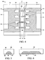
FIG. 5 is a cross-sectional taken along cut-line 5-5 ofFIG. 4 showing a cross-section of a depression with the material in the depression. -
FIG. 6 is a cross-sectional taken along cut-line 6-6 ofFIG. 4 showing a cross-section of a depression with the material in the depression. -
FIG. 7 is a top isometric view of a package produced from a strip similar to the strip ofFIG. 1 when the material in the depressions is a wettable material that is present in depressions during singulation and remains in a recess at an external corner of each lead after singulation, and showing the wettable material in the recess of the external corner of each lead, in accordance with the invention. -
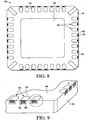
FIG. 8 is a bottom plan view of the semiconductor package ofFIG. 7 . -
FIG. 9 is a perspective view of an enlargement of an encircled region shown inFIG. 8 showing several recesses and showing the wettable material in the recesses. -
FIG. 10 is a perspective view of an enlargement of an encircled region shown inFIG. 9 showing one recess and showing the wettable material in the recess. -
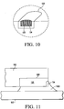
FIG. 11 is a partial, side-elevational view illustrating the manner in which the package ofFIGS. 7-10 is mounted to a PCB, and showing a fillet. -
FIG. 12 is a top isometric view of a package produced from a strip similar to the strip ofFIG. 1 when the material in the depressions is a removable material that is present in the depressions during singulation and is removed after singulation, and showing a debris-free recess at an external corner of each lead after the removable material is removed, in accordance with an example useful for understanding the invention. -
FIG. 13 is a bottom plan view of the package ofFIG. 12 . -
FIG. 14 is a perspective view of an enlargement of an encircled region shown inFIG. 13 showing several debris-free recesses. -
FIG. 15 is a perspective view of an enlargement of an encircled region shown inFIG. 14 showing one debris-free recess. -
FIG. 16 is a perspective view of an enlargement of a prior art recess showing debris in the prior art recess. -
FIG. 17 is a partial, side-elevational view illustration the manner in which a prior art package that includes the prior art recess ofFIG. 16 is mounted to a PCB and shows how formation of a fillet is adversely affected by debris in the prior art recess. -
FIG. 18 is a flow diagram of a method of assembling a flat-pack no-lead package in accordance with one embodiment of the invention. -
FIG. 19 is a flow diagram of a method of assembling a flat-pack no-lead package in accordance with the example useful for understanding the invention. -
FIG. 20 is plan view of a strip, given by way of example, which may be used in one or more methods of assembling packages in accordance with the invention. -
FIG. 1 is a bottom plan view of a portion of a dual, flat-pack no-lead type strip 110 including portions of two adjacent lead frames 112, showingdepressions 130 in eachlead frame 112. Filling thedepressions 130 in each lead frame with an appropriate material prior to saw singulation prevents formation and accumulation of debris within recesses of wettable flanks of the leads of each flat-pack no-lead package produced from thestrip 110, thereby facilitating saw singulation and/or allowing a wider process window for saw singulation. The methods in accordance with the invention prevent accumulation of debris in the recesses during assembly of QFN-style packages. Performing saw singulation when material is in thedepressions 130 prevents the formation of copper burrs in the recesses. -
FIG. 2 is a cross-sectional taken along line 2-2 of thestrip 110. Eachlead 120 has abottom surface 128 and atop surface 226. -
FIG. 3 is a cross-sectional taken along line 3-3 of thestrip 110. -
FIG. 4 is a bottom plan view of the portion of thestrip 110 with a material 400 disposed in thedepressions 130. -
FIG. 5 is a cross-sectional taken along cut-line 5-5 of thestrip 110 showing a cross-section of adepression 130 with the material 400 in the depression. -
FIG. 6 is a cross-sectional taken along cut-line 6-6 of thestrip 110 showing a cross-section of adepression 130 with the material 400 in the depression. Thematerial 400 is represented by cross hatching in thedepressions 130 ofFIGS. 4, 5 and 6 . As explained more fully hereinbelow, thematerial 400 is a solder wettable material (hereinafter "wettable material") 200. - Each
lead frame 112 of thestrip 110 includes anouter frame structure 114 that surrounds a centrally positionedopening 116 into which the mold compound, shown diagonally hatched, penetrates during encapsulation. Thelead frame 112 may include adie pad 118 disposed within theopening 116. The successive lead frames 112 of thestrip 110 may extend in a two dimensional matrix presenting rows and columns of lead frames. Eachlead frame 112 further comprises sets ofleads 120 disposed side by side at intervals along respective sides of eachlead frame 112 and separated from adjacent lead frames by a gap G. - Before encapsulation, semiconductor dies (not shown) are mounted on and attached to respective lead frames 112. Electrical connections are made between bonding pads (not shown) on the die and respective ones of the
leads 120 using wires. The lead frames 112 are then encapsulated by applying the mold compound to thestrip 110, either to the entire strip, or to form individual moldings for individual packages. - Before singulation, as shown in
FIGS. 1 and4 , theleads 120 are integrally connected to, and supported by, theouter frame structure 114 and extend inward into theopening 116 toward the peripheral edge of thedie pad 118. In eachstrip 110, theouter frame structure 114 includes an intermediatecommon bar 132, which are common to adjacent lead frames 112. Theouter frame structure 114, including thecommon bar 132, is cut away and discarded during singulation. - As shown in
FIGS. 1 and4 , thedepressions 130 of theleads 120 of adjacent lead frames 112 within the same column or row, may be formed by semi-etching or partial-etching, which is etching the material of thestrip 110 part-way through its thickness. The partial-etching forms partially-etched, elongateddepressions 130 extending across thecommon bar 132 of theouter frame structure 114 common to adjacent lead frames, so that the opposite end portions of thedepressions 130 later form (after singulation) recesses 134 at the ends of the juxtaposed leads 120 of the adjacent lead frames. - A saw street S of the
strip 110 extends along thecommon bar 132. The passage of a saw blade along each saw street S separates the adjacent lead frames 112 from each other. Orthogonal row and column saw streets S extend within a two-dimensional strip 110. A width of a blade used in the saw singulation process is such that the saw street S does not include the opposed end portions of eachdepression 130. - Typically, the saw blade is the same width as each of the saw streets S and straddles the
common bar 132 of theouter frame structure 114 while it is sawing. Thus, during the saw singulation process, the saw blade cuts along each saw street S longitudinally, cutting into and along thecommon bar 132 of eachouter frame structure 114, which reduces all the metal material of thecommon bar 132 to swarf, which is discarded, and further removes or severs a portion of each of theleads 120 to form their outer ends at the peripheral edge surfaces of thepackage 140, in addition to cutting the mold compound. The saw singulation process also cuts away the middle portion ofdepressions 130. -
FIG. 7 is a top isometric view of a completed quad, flat-pack no-lead package 140 when the material 400 in the partially-etcheddepressions 130 is thewettable material 200, which was present in the partially-etched depressions during singulation. Thepackage 140 illustrated inFIG. 7 was manufactured, or assembled, utilizing a first method (seeFIG. 18 ) in accordance with one embodiment of the invention.FIG. 7 shows thewettable material 200 in the recess of the external corner of each lead 120 of thepackage 140. -
FIG. 8 is a bottom plan view of thepackage 140. Thewettable material 200 is represented as a small solid dark area in each recess ofFIGS. 7 and8 . -
FIG. 9 is a perspective view of an enlargement of an encircled region shown inFIG. 8 showingseveral recesses 134 and showing thewettable material 200 in the recesses as cross-hatching. -
FIG. 10 is a perspective view of an enlargement of an encircled region shown inFIG. 9 showing onerecess 134 and showing thewettable material 200 in the recess as cross-hatching. - The
package 140 includes a package body (hereinafter "body") 142 formed by the hardening of electrically insulating plastic encapsulation material, or mold compound, which is applied to a strip such as thestrip 110. Eachpackage 140 comprises sets of discrete, electrical contact elements or leads 120 disposed side by side at intervals along respective sides of thebottom face 146 of the package and extending perpendicularly to the side of the correspondingbottom face 146. Inpackage 140, sets ofleads 120 are disposed on all four sides of thebottom face 146 and are exposed at thebottom face 146 and at the side edges 150 of the package for soldering to the electrical connections of the support. In a dual no-lead package (not shown), sets ofleads 120 are disposed on only two opposed sides of thebottom face 146. As shown inFIGS. 7-10 , the ends of theleads 120 of thepackage 140 terminate approximately flush with the sides of the singulated, completed package. - The saw singulation process separates the
packages 140 from each other by cutting and separating both the individual lead frames 112 of thestrip 110 and the plastic encapsulation material in a manner completing the formation of thebody 142 of eachpackage 140. The completely formedpackage 140 defines atop face 144 and an opposingbottom face 146, which are generally rectangular. Aside edge 150 extends transversely to thetop face 144 andbottom face 146 of thebody 142. - The leads are exposed within the
bottom face 146 of thebody 142. The outer ends of theleads 120 are exposed within the side edges 150 of thebody 142. The leads haverecesses 134 formed at a corner of each lead 120 formed by thebottom surface 128 of each lead and the exposed outer end of each lead 120 of apackage 140. Thebottom surface 128 of each lead near this corner functions as an electrical contact portion of each lead. Completion of the saw singulation process results in arecess 134 being formed within eachlead 120. Eachrecess 134 is formed in a corner region of thecorresponding lead 120 defined by an outer end and thebottom surface 128 thereof. Therecess 134 is disposed within thebottom surface 128 and the outer end, but does not extend to thetop surface 226 or either of the side surfaces. Eachrecess 134 has a generally concave configuration. During solder mounting of thepackage 140 on a PCB 152 (seeFIG. 11 ), solder can reflow up into therecesses 134. The electrical contact surface portions and outer end, including therecesses 134, of each lead 120 (which are exposed outside of the body 142) may have a plating layer applied to facilitate soldering to thePCB 152. - The methods in accordance with the invention overcome the problem of burrs and debris collecting in the
recess 134 during saw singulation ofpackages 140. The methods in accordance with the invention filldepressions 130 with thewettable material 200. In an illustrative example not falling within the terms of the claims, a removable material 300 may be used. The removable material 300 does not compromise the wettability of thelead 120 or of therecess 134. The removable material 300 has one of rigid and semi-rigid properties when singulation is performed; however, the removable material may be fluidic when it is placed in thedepressions 130. Adepression 130 that is filled withmaterial 400 at time of singulation eliminates (or at least effectively eliminates) debris that would otherwise accumulate in therecesses 134 as a result of singulation, especially saw singulation. Much of the debris that accumulates in therecesses 134 as a result of using known methods of singulation may disadvantageously remain in the recesses indefinitely. The methods in accordance with the invention improve the ability to produce a debris-free recess 134 inpackages 140 with fine pitch leads 120 by preventing accumulation of debris in the recess during assembly of the package. The methods in accordance with the invention increases a likelihood of forming an inspectable solder joint after mounting on thePCB 152. The methods in accordance with the invention fill thedepression 130 with a material 400 that is solid enough to prevent formation of burrs, or tear-outs, during, and as a result of, saw singulation. - A method in accordance with the invention fills the
depressions 130 prior to singulation with thewettable material 200, which prevents formation and accumulation of burrs and debris during singulation, and does not require removal. With the method, thedepression 130 is filled with thewettable material 200 such as solder, which is typically tin alloyed with copper, lead, silver or bismuth. In various embodiments, thewettable material 200 is solder, solder paste, tin, bismuth, indium, gold, silver, another wettable material, or combinations thereof. In one embodiment, the solder is SAC305 or SAC405, where S = tin, A = silver and C = copper. For example, SAC305 is 96.5% tin, 3% silver, and 0.5% copper. Thedepressions 130 may be filled with thewettable material 200 in several ways. The first method fills thedepression 130 with thewettable material 200 by squeegee application, stencil print or screen print to move solder paste into thedepressions 130, then reflows the wettable material prior to continuing with normal assembly of thepackage 140. In another embodiment, a solder jet is used which streams solder paste through a small nozzle to fill thedepressions 130. In another embodiment, solder paste that has been atomized into nanoparticles is sprayed into thedepressions 130. In another embodiment, solder balls are placed into eachdepression 130. The solder balls are then melted or reflowed to fill thedepressions 130. In another embodiment, thestrip 110 is masked such that only thedepressions 130 are exposed, wherein thewettable material 200 is formed in the openings of a mask. In another embodiment, thestrip 110 is plated with thewettable material 200 until thedepressions 130 become filled. In some embodiments of the first method, thewettable material 200 that is placed in thedepressions 130 is then heated to reflow the wettable material. In each embodiment of the first method, thestrip 110 is singulated after thewettable material 200 is placed in thedepressions 130. In each embodiment of the first method, thewettable material 200 is not removed after it is placed in thedepressions 130. Maintaining thewettable material 200 in thedepression 130 after singulation prevents any further accumulation of debris in therecess 134 after singulation. - A method in accordance with an illustrative example not falling within the terms of the claims fills the
depression 130 prior to singulation with a removable material 300 that can be hard enough to prevent the burrs and debris from collecting in therecess 134, and that is easily removable using water or other chemistry common to semiconductor processing (such as photo resist). The removable material 300 may be one of a hot-water soluble adhesive, a hot-water soluble thermoplastic material and a hot-water soluble thermosetting polymer material. The hot-water soluble material is applied at a high enough temperature (about 100°C) for the material to be in a liquid form. The hot-water soluble material is adequately solid when cured, but, after it has cured, it rinses cleanly away in hot-water. An example of such a hot-water soluble material that can be used is AquaBond® ABS-65 (AquaBond is a trademark of AquaBond Technologies, Inc., of Camarillo, CA). Thestrip 110 may be put into a bath of the hot-water soluble material at a high enough temperature (about 100°C) for the material to be in a liquid form. The hot-water soluble material may be heated to a high enough temperature (about 100°C) for the material to be in a liquid form, and it is applied to thestrip 110 by screen printing using a stencil. Then, the hot-water soluble removable material 300 on thestrip 110 is allowed to return to room temperature, and the hot-water soluble removable material hardens or solidifies, and it becomes at least semi-rigid. Therecesses 134 remain filled with the hot-water soluble removable material 300 during singulation, which prevents debris from entering therecess 134 during the saw singulation process. Next, the partially singulated strip or the individual units are put into a hot-water bath to remove the hot-water soluble removable material 300 from therecess 134. An exposed debris-free recess 134 results. The partially singulated strip or the individual units may be immersed in hot-water or sprayed with hot-water (at about 80-90°C) until the hot-water soluble removable material 300 dissolves. - The application of the hot-water soluble removable material 300 to the
strip 110 is a last step prior to singulation. The immersion of the partially singulated strip or the individual units in hot-water or the spraying the partially singulated strip or the individual units with hot-water is a first step after saw singulation. - The removable material 300 may be a polyvinylpyrrolidone polymer, which is a hot-water soluble thermosetting polymer material that is cured using ultraviolet (UV) light. An example of such a polyvinylpyrrolidone polymer is Dymax® UV Curable Water Soluble Masks 9-20553 Series (Dymax is a trademark of Dymax Corporation of Torrington, CT). After the polyvinylpyrrolidone polymer is cured, the
strip 110 is singulated. Thestrip 110 may be partially sawn, thereby producing a partially singulated strip. Thestrip 110 may be sawn through completely, thereby singulating the strip into individual units. After singulation, the partially singulated strip or the individual units are immersed in hot-water or sprayed with hot-water (at about 120-150°C) until the polyvinylpyrrolidone polymer dissolves, thereby removing the polyvinylpyrrolidone polymer from therecess 134, and revealing a debris-free recess. - The removable material 300 may be polyimide, and the polyimide is removed, using acetone, after singulation, and revealing a
recess 134 that is debris-free. - In various other examples, the removable material 300 is another type of polymer, a polymer adhesive, or a photo-resist material, which is then removed after singulation, and revealing a
recess 134 that is debris-free. - A partial saw procedure may be performed on the
strip 110 after depositing the removable material 300 to allow for removal of the removable material 300 while the strip is still in strip form. Thestrip 110 may be partially sawn, which means sawn entirely through themetal lead frame 112 including through the removable material 300, but not sawn through themold compound 116, thereby producing a partially singulated strip. The removable material 300 can be removed from thedepressions 130 of the partially singulated strip without debris remaining in therecesses 134 because themetal lead frame 112 has already been cut through and because a primary cause for debris is from cutting of the metal lead frame. The partial saw procedure may use a blade that is slightly wider than a blade used for a through cut to ensure that themetal lead 120 is not accidently "clipped" when full singulation is completed after removing the removable material 300. Alternatively, thestrip 110 is sawn through completely, thereby singulating the strip into fully singulated individual units. - In the illustrative example, the
strip 110 is singulated or partially singulated after the removable material 300 is placed in thedepressions 130 and only while the removable material is in the depressions. In the illustrative example, after thestrip 110 is singulated or partially singulated, the removable material 300 is removed. -
FIG. 11 is a partial, side-elevational view illustrating the manner in which thepackage 140 assembled in accordance with the invention, is mounted to thePCB 152, and showing asolder fillet 1100. The method (seeFIG. 18 ) and thepackage 140 produced thereby in accordance with the invention aid in the formation of a well-formed solder fillet that can be easily inspected visually. -
FIG. 12 is a top isometric view of a quad, flat-pack no-lead package 140 that was manufactured, or assembled, utilizing the illustrative example (seeFIG. 19 ), in which a strip similar tostrip 110 was singulated while the removable material 300 was disposed in thedepressions 130. The removable material 300 was removed after singulation, and, as illustrated inFIG. 12 , there is a debris-free recess 134 at an external corner of each lead 120. -
FIG. 13 is a bottom plan view of thepackage 140. -
FIG. 14 is a perspective view of an enlargement of an encircled region shown inFIG. 13 showing several debris-free recesses 134 in accordance with the invention. -
FIG. 15 is a perspective view of an enlargement an encircled region shown inFIG. 14 showing one debris-free recess 134 in accordance with the illustrative example. The method (seeFIG. 19 ), and thepackage 140 produced thereby, results in the debris-free recess 134 shown inFIG. 15 . -
FIG. 16 is a perspective view of an enlargement of aprior art recess 1634showing debris 1635 in the prior art recess. -
FIG. 17 is a partial, side-elevational view illustration the manner in which a prior art semiconductor package, which includes aprior art body 1742 and theprior art recess 1634 in aprior art lead 1620, is mounted to aPCB 1752, and shows how formation of a priorart solder fillet 1700 is adversely affected by thedebris 1635 in the prior art recess. -
FIG. 18 is a flow diagram of a first method of assembling thepackage 140 in accordance with an embodiment of the invention that utilizes thewettable material 200. The first method starts with astandard strip 110 that hasstandard depressions 130 in the lead frames 112, which depressions are used for creatingrecesses 134 after singulation. The first method performs standard package assembly up to and including a step of encapsulation of thestrip 110 with mold compound. Next, thedepressions 130 are filled with thewettable material 200. Next, thestrip 110 is heated so thatwettable material 200 reflows, and then, the strip is allowed to cool to room temperature. Next, thestrip 110 is singulated. Advantageously, thestrip 110 is singulated in a standard way with saw standard blades and techniques, notwithstanding the presence of thewettable material 200 in thedepressions 130. Next, normal assembly is resumed. An end of the first method results in complete package assembly with solder in therecesses 134 of a completedpackage 140. -
FIG. 19 is a flow diagram of a method of assembling thepackage 140 in accordance with the illustrative example that utilizes the removable material 300. The method starts with astandard strip 110 that hasstandard depressions 130 in the lead frames 112, which depressions are used for creatingrecesses 134 after singulation. The method performs standard package assembly up to and including a step of encapsulation of thestrip 110 with mold compound. Next, thedepressions 130 are filled with the removable material 300 such as by dipping thestrip 110 into in a tank or reservoir of the removable material, or by curtain coating the strip with the removable material, or by stencil printing. Next, the removable material 300 is cured per recommendation of manufacturer of the removable material to make the removable material hard and/or stiff. Next, thestrip 110 is singulated using standard singulation techniques, or partial saw singulation is performed on the strip. Advantageously, thestrip 110 is singulated in a standard way with saw standard blades and techniques, notwithstanding the presence of the cured removable material 300 in thedepressions 130. Next, the removable material 300 is rinsed or removed from the singulated lead frames 112. Next, normal assembly is resumed. An end of the method of the illustrative example results in a completedpackage 140 having debris-free recesses 134. - In some embodiments, the
depressions 130 are filled with thematerial 400 after thestrip 110 is molded because at this stage, there is very little likelihood of contaminating other portions of the after the strip is molded. By movingwettable material 200 into thedepressions 130 after thestrip 110 is molded, there is little chance of the wettable material running down inside the lead frames 112 and contaminating wire bonds, die surfaces or die flag attach areas because they are already protected by the molding process. In other embodiments, thedepressions 130 are filled at any stage of assembly prior to singulation. - It has been determined by experimentation that the lead frames 112 can be saw singulated cleanly by proper management of blade loading without melting the
material 400 that is disposed within thedepressions 130. -
FIG. 20 is an illustration of one example of a strip such asstrip 110, which may be used in one or more methods ofassembling packages 140 in accordance with various embodiments of the invention. The strip illustrated inFIG. 20 includes three arrays of lead frames, each array including twenty-five lead frames such aslead frame 112, for a total of seventy-five lead frames. - In one embodiment, the
package 140 is a quad, flat-pack no-lead (QFN) package (hereinafter "QFN-style package"). Examples of QFN-style packages are: a power quad flat-pack no-lead (PQFN) package, an extremely-thin quad flat-pack no-lead (XQFN) package, a depopulated very-thin quad flat-pack no-lead (DQFN) package, and a heatsink very-thin quad flat-pack no-lead (HVQFN) package. QFN-style packages may also include other types of flat-pack no-lead packages. In another embodiment, thepackage 140 is a dual flat-pack no-lead (DFN) package. - Although a person of skill in the art will note that
FIGS. 1 and4 illustrate a strip used in assembling a dual flat-pack no-lead type package, and thatFIGS. 7-9 and12-14 illustrate a quad flat-pack no-lead type package, for ease of description, these will be treated as showing a same product, because the method in accordance with the present invention is applicable equally to both quad and dual flat-pack no-lead type packages. - The specification and figures are to be regarded in an illustrative rather than a restrictive sense, and all such modifications are intended to be included within the scope of the present invention. Any benefits, advantages or solutions to problems described herein with regard to specific embodiments are not intended to be construed as a critical, required or essential feature or element of any or all the claims. Unless stated otherwise, terms such as "first" and "second" are used to arbitrarily distinguish between the elements such terms describe. Thus, these terms are not necessarily intended to indicate temporal or other prioritization of such elements. Note that the term "couple" has been used to denote that one or more additional elements may be interposed between two elements that are coupled.
- Although the invention is described herein with reference to specific embodiments, various modifications and changes can be made without departing from the scope of the present invention as set forth in the claims below.
Claims (6)
- A method, comprising:providing a lead frame strip (110), having a thickness, including a plurality of lead frames (112), wherein the lead frame strip (110) includes at least one depression (130), going only partially through the thickness of the lead frame strip (110), which becomes, after singulation of the lead frame strip (110) into individual lead frames, at least one recess (134) at a corner of an end of a lead (120) of a lead frame, wherein the lead (120) has a bottom surface (128), a top surface (226), an exposed outer end extending between the bottom and top surfaces, and side surfaces extending between the bottom and top surfaces, and wherein the recess (134) is disposed within the bottom surface (128) and the exposed outer end of the lead (120), and the recess (134) does not extend to the top surface or to either of the side surfaces;characterised by:filling the at least one depression (130) with a solder wettable material (200); andsingulating the lead frame strip (110) into individual lead frames while the at least one depression (130) is filled with the solder wettable material.
- The method of claim 1, wherein the solder wettable material is not removed after the step of singulating.
- The method of claim 2, wherein the strip is heated to reflow the solder wettable material, and wherein the strip is allowed to cool sufficiently to render the solder wettable material solid prior to the step of singulating.
- The method according to any one of claims 1-3, including, prior to the step of filling the at least one depression (130) with the solder wettable material:
encapsulating the strip with a mold compound. - The method according to any one of claims 1-3, including, after the step of filling the at least one depression (130) with the solder wettable material:
encapsulating the strip with a mold compound. - The method of any one of claims 2-5, including, after the step of singulating, steps of:producing a semiconductor device package including an individual lead frame; andmounting the semiconductor device package to a support,wherein the solder wettable material remains in the recess (134) until the semiconductor device package is mounted to the support.
Priority Applications (1)
| Application Number | Priority Date | Filing Date | Title |
|---|---|---|---|
| EP15172276.6A EP2953160B1 (en) | 2012-06-29 | 2013-06-21 | Method of manufacturing a semiconductor device package |
Applications Claiming Priority (1)
| Application Number | Priority Date | Filing Date | Title |
|---|---|---|---|
| US13/537,392 US8841758B2 (en) | 2012-06-29 | 2012-06-29 | Semiconductor device package and method of manufacture |
Related Parent Applications (2)
| Application Number | Title | Priority Date | Filing Date |
|---|---|---|---|
| US201213537392 Previously-Filed-Application | 2012-06-29 | ||
| US13/537,392 Previously-Filed-Application US8841758B2 (en) | 2012-06-29 | 2012-06-29 | Semiconductor device package and method of manufacture |
Related Child Applications (2)
| Application Number | Title | Priority Date | Filing Date |
|---|---|---|---|
| EP15172276.6A Division-Into EP2953160B1 (en) | 2012-06-29 | 2013-06-21 | Method of manufacturing a semiconductor device package |
| EP15172276.6A Division EP2953160B1 (en) | 2012-06-29 | 2013-06-21 | Method of manufacturing a semiconductor device package |
Publications (3)
| Publication Number | Publication Date |
|---|---|
| EP2680307A2 EP2680307A2 (en) | 2014-01-01 |
| EP2680307A3 EP2680307A3 (en) | 2014-12-17 |
| EP2680307B1 true EP2680307B1 (en) | 2020-03-04 |
Family
ID=48747335
Family Applications (2)
| Application Number | Title | Priority Date | Filing Date |
|---|---|---|---|
| EP15172276.6A Active EP2953160B1 (en) | 2012-06-29 | 2013-06-21 | Method of manufacturing a semiconductor device package |
| EP13173268.7A Active EP2680307B1 (en) | 2012-06-29 | 2013-06-21 | Semiconductor device package and method of manufacture |
Family Applications Before (1)
| Application Number | Title | Priority Date | Filing Date |
|---|---|---|---|
| EP15172276.6A Active EP2953160B1 (en) | 2012-06-29 | 2013-06-21 | Method of manufacturing a semiconductor device package |
Country Status (4)
| Country | Link |
|---|---|
| US (3) | US8841758B2 (en) |
| EP (2) | EP2953160B1 (en) |
| JP (2) | JP6274640B2 (en) |
| CN (2) | CN103531493A (en) |
Families Citing this family (35)
| Publication number | Priority date | Publication date | Assignee | Title |
|---|---|---|---|---|
| US8841758B2 (en) * | 2012-06-29 | 2014-09-23 | Freescale Semiconductor, Inc. | Semiconductor device package and method of manufacture |
| US20140357022A1 (en) * | 2013-06-04 | 2014-12-04 | Cambridge Silicon Radio Limited | A qfn with wettable flank |
| US9601415B2 (en) * | 2014-03-27 | 2017-03-21 | Renesas Electronics Corporation | Method of manufacturing semiconductor device and semiconductor device |
| US20160148876A1 (en) * | 2014-11-20 | 2016-05-26 | Microchip Technology Incorporated | Flat no-leads package with improved contact pins |
| CN104659010B (en) * | 2015-02-11 | 2018-03-16 | 江苏长电科技股份有限公司 | A kind of lead frame structure and package body structure of square flat pinless encapsulation |
| US10264664B1 (en) * | 2015-06-04 | 2019-04-16 | Vlt, Inc. | Method of electrically interconnecting circuit assemblies |
| JP7148220B2 (en) * | 2015-08-10 | 2022-10-05 | 株式会社アムコー・テクノロジー・ジャパン | Semiconductor package and its manufacturing method |
| US9443782B1 (en) | 2015-08-11 | 2016-09-13 | Freescale Semiconductor, Inc. | Method of bond pad protection during wafer processing |
| US9646853B1 (en) | 2015-10-15 | 2017-05-09 | Freescale Semiconductor, Inc. | IC device having patterned, non-conductive substrate |
| US10796986B2 (en) * | 2016-03-21 | 2020-10-06 | Infineon Technologies Ag | Leadframe leads having fully plated end faces |
| US10128171B1 (en) * | 2016-03-25 | 2018-11-13 | Marvell International Ltd. | Leadframe with improved half-etch layout to reduce defects caused during singulation |
| WO2017181399A1 (en) * | 2016-04-22 | 2017-10-26 | Texas Instruments Incorporated | Improved lead frame system |
| CN105932006A (en) * | 2016-06-23 | 2016-09-07 | 江阴芯智联电子科技有限公司 | Wettable lead frame structure with pre-encapsulated side and manufacturing method of wettable lead frame structure |
| US9847283B1 (en) * | 2016-11-06 | 2017-12-19 | Nexperia B.V. | Semiconductor device with wettable corner leads |
| US10535554B2 (en) | 2016-12-14 | 2020-01-14 | Taiwan Semiconductor Manufacturing Co., Ltd. | Semiconductor die having edge with multiple gradients and method for forming the same |
| TWM539698U (en) * | 2016-12-29 | 2017-04-11 | Chang Wah Technology Co Ltd | Lead frame pre-formed body with improved leads |
| US10121742B2 (en) * | 2017-03-15 | 2018-11-06 | Amkor Technology, Inc. | Method of forming a packaged semiconductor device using ganged conductive connective assembly and structure |
| JP6841550B2 (en) * | 2017-05-29 | 2021-03-10 | 大口マテリアル株式会社 | Lead frame and its manufacturing method |
| US10636729B2 (en) | 2017-06-19 | 2020-04-28 | Texas Instruments Incorporated | Integrated circuit package with pre-wetted contact sidewall surfaces |
| JP6417466B1 (en) * | 2017-11-28 | 2018-11-07 | アオイ電子株式会社 | Semiconductor device and manufacturing method thereof |
| KR20190071111A (en) * | 2017-12-14 | 2019-06-24 | 삼성전자주식회사 | An apparatus for x-ray inspection, and a method for manufacturing a semiconductor device using the same |
| US10896869B2 (en) * | 2018-01-12 | 2021-01-19 | Amkor Technology Singapore Holding Pte. Ltd. | Method of manufacturing a semiconductor device |
| JP7210868B2 (en) | 2018-09-05 | 2023-01-24 | ローム株式会社 | semiconductor equipment |
| JP7004259B2 (en) * | 2018-09-21 | 2022-02-04 | 大口マテリアル株式会社 | Lead frame and its manufacturing method |
| US11545418B2 (en) * | 2018-10-24 | 2023-01-03 | Texas Instruments Incorporated | Thermal capacity control for relative temperature-based thermal shutdown |
| SG10201810052WA (en) | 2018-11-12 | 2020-06-29 | Delta Electronics Int’L Singapore Pte Ltd | Packaging process and packaging structure |
| US11073572B2 (en) * | 2019-01-17 | 2021-07-27 | Infineon Technologies Ag | Current sensor device with a routable molded lead frame |
| EP3736857A1 (en) * | 2019-05-07 | 2020-11-11 | Nexperia B.V. | Through hole side wettable flank |
| US11562948B2 (en) * | 2019-11-04 | 2023-01-24 | Mediatek Inc. | Semiconductor package having step cut sawn into molding compound along perimeter of the semiconductor package |
| JP7391694B2 (en) | 2020-02-06 | 2023-12-05 | 新光電気工業株式会社 | Lead frame, semiconductor device, and lead frame manufacturing method |
| CN111298853B (en) * | 2020-02-27 | 2021-08-10 | 西人马联合测控(泉州)科技有限公司 | Chip cutting and forming method and wafer |
| TWI723932B (en) * | 2020-08-06 | 2021-04-01 | 強茂股份有限公司 | Side wettable package component and its manufacturing method |
| US11611170B2 (en) | 2021-03-23 | 2023-03-21 | Amkor Technology Singapore Holding Pte. Ltd | Semiconductor devices having exposed clip top sides and methods of manufacturing semiconductor devices |
| KR102514564B1 (en) * | 2021-06-28 | 2023-03-29 | 해성디에스 주식회사 | Lead frame including grooved lead |
| JP2023039266A (en) * | 2021-09-08 | 2023-03-20 | Towa株式会社 | Method of manufacturing semiconductor device and lead frame |
Family Cites Families (57)
| Publication number | Priority date | Publication date | Assignee | Title |
|---|---|---|---|---|
| JPS629639A (en) | 1985-07-05 | 1987-01-17 | Nec Yamagata Ltd | Manufacture of semiconductor device |
| KR960006710B1 (en) | 1987-02-25 | 1996-05-22 | 가부시기가이샤 히다찌세이사꾸쇼 | Surface mount plastic package semiconductor integrated circuit and the manufacturing method thereof and well asmount struct |
| US5391439A (en) | 1990-09-27 | 1995-02-21 | Dai Nippon Printing Co., Ltd. | Leadframe adapted to support semiconductor elements |
| JP2934357B2 (en) | 1992-10-20 | 1999-08-16 | 富士通株式会社 | Semiconductor device |
| US5444293A (en) | 1993-09-22 | 1995-08-22 | Opl Limited | Structure and method for providing a lead frame with enhanced solder wetting leads |
| JPH08306853A (en) | 1995-05-09 | 1996-11-22 | Fujitsu Ltd | Semiconductor device, manufacture thereof and manufacture of lead frame |
| JPH09312375A (en) * | 1996-03-18 | 1997-12-02 | Hitachi Ltd | Lead frame, semiconductor device and manufacture thereof |
| US5804880A (en) | 1996-11-04 | 1998-09-08 | National Semiconductor Corporation | Solder isolating lead frame |
| US6201292B1 (en) | 1997-04-02 | 2001-03-13 | Dai Nippon Insatsu Kabushiki Kaisha | Resin-sealed semiconductor device, circuit member used therefor |
| EP0895287A3 (en) * | 1997-07-31 | 2006-04-05 | Matsushita Electric Industrial Co., Ltd. | Semiconductor device and lead frame for the same |
| US8330270B1 (en) * | 1998-06-10 | 2012-12-11 | Utac Hong Kong Limited | Integrated circuit package having a plurality of spaced apart pad portions |
| JP2000223643A (en) * | 1999-02-02 | 2000-08-11 | Oita Nippon Denki Kk | Lead frame and method of forming lead frame |
| US6420779B1 (en) | 1999-09-14 | 2002-07-16 | St Assembly Test Services Ltd. | Leadframe based chip scale package and method of producing the same |
| US6333252B1 (en) | 2000-01-05 | 2001-12-25 | Advanced Semiconductor Engineering, Inc. | Low-pin-count chip package and manufacturing method thereof |
| US6342730B1 (en) | 2000-01-28 | 2002-01-29 | Advanced Semiconductor Engineering, Inc. | Low-pin-count chip package and manufacturing method thereof |
| US6261864B1 (en) | 2000-01-28 | 2001-07-17 | Advanced Semiconductor Engineering, Inc. | Low-pin-count chip package and manufacturing method thereof |
| US6306685B1 (en) | 2000-02-01 | 2001-10-23 | Advanced Semiconductor Engineering, Inc. | Method of molding a bump chip carrier and structure made thereby |
| US6238952B1 (en) | 2000-02-29 | 2001-05-29 | Advanced Semiconductor Engineering, Inc. | Low-pin-count chip package and manufacturing method thereof |
| US6452255B1 (en) * | 2000-03-20 | 2002-09-17 | National Semiconductor, Corp. | Low inductance leadless package |
| JP2001320007A (en) | 2000-05-09 | 2001-11-16 | Dainippon Printing Co Ltd | Frame for resin sealed semiconductor device |
| US6400004B1 (en) | 2000-08-17 | 2002-06-04 | Advanced Semiconductor Engineering, Inc. | Leadless semiconductor package |
| US6608366B1 (en) | 2002-04-15 | 2003-08-19 | Harry J. Fogelson | Lead frame with plated end leads |
| US7423337B1 (en) | 2002-08-19 | 2008-09-09 | National Semiconductor Corporation | Integrated circuit device package having a support coating for improved reliability during temperature cycling |
| US7105383B2 (en) | 2002-08-29 | 2006-09-12 | Freescale Semiconductor, Inc. | Packaged semiconductor with coated leads and method therefore |
| JP3866178B2 (en) | 2002-10-08 | 2007-01-10 | 株式会社ルネサステクノロジ | IC card |
| US6723585B1 (en) | 2002-10-31 | 2004-04-20 | National Semiconductor Corporation | Leadless package |
| JP3736516B2 (en) | 2002-11-01 | 2006-01-18 | 松下電器産業株式会社 | Lead frame and manufacturing method thereof, resin-encapsulated semiconductor device and manufacturing method thereof |
| US6872599B1 (en) | 2002-12-10 | 2005-03-29 | National Semiconductor Corporation | Enhanced solder joint strength and ease of inspection of leadless leadframe package (LLP) |
| US6867481B2 (en) | 2003-04-11 | 2005-03-15 | Fairchild Semiconductor Corporation | Lead frame structure with aperture or groove for flip chip in a leaded molded package |
| JP4645071B2 (en) | 2003-06-20 | 2011-03-09 | 日亜化学工業株式会社 | Package molded body and semiconductor device using the same |
| CN100490140C (en) | 2003-07-15 | 2009-05-20 | 飞思卡尔半导体公司 | Double gauge lead frame |
| US7030469B2 (en) | 2003-09-25 | 2006-04-18 | Freescale Semiconductor, Inc. | Method of forming a semiconductor package and structure thereof |
| TWI338358B (en) | 2003-11-19 | 2011-03-01 | Rohm Co Ltd | Method of fabricating lead frame and method of fabricating semiconductor device using the same, and lead frame and semiconductor device using the same |
| JP2005191240A (en) * | 2003-12-25 | 2005-07-14 | Renesas Technology Corp | Semiconductor device and method for manufacturing the same |
| US7005325B2 (en) | 2004-02-05 | 2006-02-28 | St Assembly Test Services Ltd. | Semiconductor package with passive device integration |
| JP2006179760A (en) | 2004-12-24 | 2006-07-06 | Yamaha Corp | Semiconductor package and lead frame used therefor |
| JP4207004B2 (en) | 2005-01-12 | 2009-01-14 | セイコーエプソン株式会社 | Manufacturing method of semiconductor device |
| JP4408082B2 (en) | 2005-01-14 | 2010-02-03 | シャープ株式会社 | Integrated circuit package design method and manufacturing method |
| JP4207934B2 (en) | 2005-08-09 | 2009-01-14 | 三菱電機株式会社 | 4 direction lead flat package IC mounting printed wiring board, 4 direction lead flat package IC soldering method, air conditioner. |
| US7256481B2 (en) | 2005-11-30 | 2007-08-14 | Texas Instruments Incorporated | Leadframes for improved moisture reliability and enhanced solderability of semiconductor devices |
| US7943431B2 (en) * | 2005-12-02 | 2011-05-17 | Unisem (Mauritius) Holdings Limited | Leadless semiconductor package and method of manufacture |
| JP2007214185A (en) | 2006-02-07 | 2007-08-23 | Denso Corp | Lead frame |
| US7405106B2 (en) | 2006-05-23 | 2008-07-29 | International Business Machines Corporation | Quad flat no-lead chip carrier with stand-off |
| US7402459B2 (en) | 2006-07-10 | 2008-07-22 | Shanghai Kaihong Technology Co., Ltd. | Quad flat no-lead (QFN) chip package assembly apparatus and method |
| JP5259978B2 (en) * | 2006-10-04 | 2013-08-07 | ローム株式会社 | Manufacturing method of semiconductor device |
| US7489026B2 (en) | 2006-10-31 | 2009-02-10 | Freescale Semiconductor, Inc. | Methods and apparatus for a Quad Flat No-Lead (QFN) package |
| JP5122835B2 (en) * | 2007-02-27 | 2013-01-16 | ローム株式会社 | Semiconductor device, lead frame, and manufacturing method of semiconductor device |
| CN101540289B (en) | 2008-03-19 | 2012-12-19 | 飞思卡尔半导体公司 | Semiconductor integrated circuit package and method and mould for packaging semiconductor integrated circuit |
| WO2009125250A1 (en) | 2008-04-11 | 2009-10-15 | Freescale Semiconductor, Inc. | Integrated circuit package, method of manufacturing an integrated circuit package and printed circuit board |
| US20100133693A1 (en) * | 2008-12-03 | 2010-06-03 | Texas Instruments Incorporated | Semiconductor Package Leads Having Grooved Contact Areas |
| JP2011077278A (en) * | 2009-09-30 | 2011-04-14 | Sanyo Electric Co Ltd | Semiconductor device, and method of manufacturing the same |
| US8501539B2 (en) * | 2009-11-12 | 2013-08-06 | Freescale Semiconductor, Inc. | Semiconductor device package |
| US8329509B2 (en) * | 2010-04-01 | 2012-12-11 | Freescale Semiconductor, Inc. | Packaging process to create wettable lead flank during board assembly |
| CN102237280A (en) | 2010-04-23 | 2011-11-09 | 飞思卡尔半导体公司 | Semiconductor device assembling method comprising step of saw singulation |
| US8017447B1 (en) * | 2010-08-03 | 2011-09-13 | Linear Technology Corporation | Laser process for side plating of terminals |
| CN102969291A (en) | 2011-08-30 | 2013-03-13 | 飞思卡尔半导体公司 | Quad flat no-lead (QFN) device and lead frame thereof |
| US8841758B2 (en) * | 2012-06-29 | 2014-09-23 | Freescale Semiconductor, Inc. | Semiconductor device package and method of manufacture |
-
2012
- 2012-06-29 US US13/537,392 patent/US8841758B2/en active Active
-
2013
- 2013-06-18 JP JP2013128002A patent/JP6274640B2/en active Active
- 2013-06-21 EP EP15172276.6A patent/EP2953160B1/en active Active
- 2013-06-21 EP EP13173268.7A patent/EP2680307B1/en active Active
- 2013-06-28 CN CN201310267888.0A patent/CN103531493A/en active Pending
- 2013-06-28 CN CN201811247780.4A patent/CN109599344A/en not_active Withdrawn
-
2014
- 2014-08-07 US US14/453,902 patent/US9093436B2/en active Active
-
2015
- 2015-04-27 US US14/696,917 patent/US9455216B2/en active Active
-
2016
- 2016-12-27 JP JP2016252846A patent/JP6366205B2/en active Active
Non-Patent Citations (1)
| Title |
|---|
| None * |
Also Published As
| Publication number | Publication date |
|---|---|
| JP2017085141A (en) | 2017-05-18 |
| CN103531493A (en) | 2014-01-22 |
| US9455216B2 (en) | 2016-09-27 |
| US9093436B2 (en) | 2015-07-28 |
| US20150228560A1 (en) | 2015-08-13 |
| CN109599344A (en) | 2019-04-09 |
| US20140001616A1 (en) | 2014-01-02 |
| EP2953160A3 (en) | 2016-03-02 |
| JP6366205B2 (en) | 2018-08-01 |
| EP2680307A2 (en) | 2014-01-01 |
| JP6274640B2 (en) | 2018-02-07 |
| US8841758B2 (en) | 2014-09-23 |
| EP2680307A3 (en) | 2014-12-17 |
| US20140338956A1 (en) | 2014-11-20 |
| JP2014011457A (en) | 2014-01-20 |
| EP2953160B1 (en) | 2019-09-11 |
| EP2953160A2 (en) | 2015-12-09 |
Similar Documents
| Publication | Publication Date | Title |
|---|---|---|
| EP2680307B1 (en) | Semiconductor device package and method of manufacture | |
| KR102178587B1 (en) | Method for manufacturing semiconductor device and semiconductor device | |
| US10366948B2 (en) | Semiconductor device and method for manufacturing the same | |
| KR101645771B1 (en) | Semiconductor device and method for manufacturing same | |
| US8017447B1 (en) | Laser process for side plating of terminals | |
| US9431273B2 (en) | Method for manufacturing a resin-encapsulated semiconductor device | |
| US8501539B2 (en) | Semiconductor device package | |
| US20080246132A1 (en) | Semiconductor device and method of manufacturing semiconductor device | |
| US9363901B2 (en) | Making a plurality of integrated circuit packages | |
| JP2003209216A (en) | Lead frame, resin sealed die and method for manufacturing semiconductor device using them | |
| US20220319869A1 (en) | Package assembly for plating with selective molding | |
| KR20230074423A (en) | Side-solderable leadless package | |
| US20200135621A1 (en) | Leads for leadframe and semiconductor package | |
| CN110943064A (en) | Lead frame and method of manufacturing the same | |
| US20030143779A1 (en) | Semiconductor device and method for manufacturing the same | |
| CN109904077B (en) | Packaging method of multi-pin semiconductor product | |
| JP2004087883A (en) | Lead frame and method for manufacturing semiconductor device using the same | |
| WO2022231652A1 (en) | Method of forming a surface-mount integrated circuit package with solder enhanced leadframe terminals | |
| JP2004158594A (en) | Resin sealing metal mold, and method using same for manufacturing semiconductor device |
Legal Events
| Date | Code | Title | Description |
|---|---|---|---|
| PUAI | Public reference made under article 153(3) epc to a published international application that has entered the european phase |
Free format text: ORIGINAL CODE: 0009012 |
|
| AK | Designated contracting states |
Kind code of ref document: A2 Designated state(s): AL AT BE BG CH CY CZ DE DK EE ES FI FR GB GR HR HU IE IS IT LI LT LU LV MC MK MT NL NO PL PT RO RS SE SI SK SM TR |
|
| AX | Request for extension of the european patent |
Extension state: BA ME |
|
| PUAL | Search report despatched |
Free format text: ORIGINAL CODE: 0009013 |
|
| RIC1 | Information provided on ipc code assigned before grant |
Ipc: H01L 21/56 20060101ALI20141016BHEP Ipc: H01L 23/495 20060101AFI20141016BHEP |
|
| AK | Designated contracting states |
Kind code of ref document: A3 Designated state(s): AL AT BE BG CH CY CZ DE DK EE ES FI FR GB GR HR HU IE IS IT LI LT LU LV MC MK MT NL NO PL PT RO RS SE SI SK SM TR |
|
| AX | Request for extension of the european patent |
Extension state: BA ME |
|
| RIC1 | Information provided on ipc code assigned before grant |
Ipc: H01L 23/495 20060101AFI20141111BHEP Ipc: H01L 21/56 20060101ALI20141111BHEP |
|
| 17P | Request for examination filed |
Effective date: 20150617 |
|
| RBV | Designated contracting states (corrected) |
Designated state(s): AL AT BE BG CH CY CZ DE DK EE ES FI FR GB GR HR HU IE IS IT LI LT LU LV MC MK MT NL NO PL PT RO RS SE SI SK SM TR |
|
| 17Q | First examination report despatched |
Effective date: 20160225 |
|
| RAP1 | Party data changed (applicant data changed or rights of an application transferred) |
Owner name: NXP USA, INC. |
|
| STAA | Information on the status of an ep patent application or granted ep patent |
Free format text: STATUS: EXAMINATION IS IN PROGRESS |
|
| GRAP | Despatch of communication of intention to grant a patent |
Free format text: ORIGINAL CODE: EPIDOSNIGR1 |
|
| STAA | Information on the status of an ep patent application or granted ep patent |
Free format text: STATUS: GRANT OF PATENT IS INTENDED |
|
| INTG | Intention to grant announced |
Effective date: 20191121 |
|
| GRAS | Grant fee paid |
Free format text: ORIGINAL CODE: EPIDOSNIGR3 |
|
| GRAA | (expected) grant |
Free format text: ORIGINAL CODE: 0009210 |
|
| STAA | Information on the status of an ep patent application or granted ep patent |
Free format text: STATUS: THE PATENT HAS BEEN GRANTED |
|
| AK | Designated contracting states |
Kind code of ref document: B1 Designated state(s): AL AT BE BG CH CY CZ DE DK EE ES FI FR GB GR HR HU IE IS IT LI LT LU LV MC MK MT NL NO PL PT RO RS SE SI SK SM TR |
|
| REG | Reference to a national code |
Ref country code: GB Ref legal event code: FG4D |
|
| REG | Reference to a national code |
Ref country code: CH Ref legal event code: EP |
|
| REG | Reference to a national code |
Ref country code: AT Ref legal event code: REF Ref document number: 1241346 Country of ref document: AT Kind code of ref document: T Effective date: 20200315 |
|
| REG | Reference to a national code |
Ref country code: DE Ref legal event code: R096 Ref document number: 602013066393 Country of ref document: DE |
|
| REG | Reference to a national code |
Ref country code: IE Ref legal event code: FG4D |
|
| PG25 | Lapsed in a contracting state [announced via postgrant information from national office to epo] |
Ref country code: RS Free format text: LAPSE BECAUSE OF FAILURE TO SUBMIT A TRANSLATION OF THE DESCRIPTION OR TO PAY THE FEE WITHIN THE PRESCRIBED TIME-LIMIT Effective date: 20200304 Ref country code: NO Free format text: LAPSE BECAUSE OF FAILURE TO SUBMIT A TRANSLATION OF THE DESCRIPTION OR TO PAY THE FEE WITHIN THE PRESCRIBED TIME-LIMIT Effective date: 20200604 Ref country code: FI Free format text: LAPSE BECAUSE OF FAILURE TO SUBMIT A TRANSLATION OF THE DESCRIPTION OR TO PAY THE FEE WITHIN THE PRESCRIBED TIME-LIMIT Effective date: 20200304 |
|
| REG | Reference to a national code |
Ref country code: NL Ref legal event code: MP Effective date: 20200304 |
|
| PG25 | Lapsed in a contracting state [announced via postgrant information from national office to epo] |
Ref country code: HR Free format text: LAPSE BECAUSE OF FAILURE TO SUBMIT A TRANSLATION OF THE DESCRIPTION OR TO PAY THE FEE WITHIN THE PRESCRIBED TIME-LIMIT Effective date: 20200304 Ref country code: SE Free format text: LAPSE BECAUSE OF FAILURE TO SUBMIT A TRANSLATION OF THE DESCRIPTION OR TO PAY THE FEE WITHIN THE PRESCRIBED TIME-LIMIT Effective date: 20200304 Ref country code: LV Free format text: LAPSE BECAUSE OF FAILURE TO SUBMIT A TRANSLATION OF THE DESCRIPTION OR TO PAY THE FEE WITHIN THE PRESCRIBED TIME-LIMIT Effective date: 20200304 Ref country code: GR Free format text: LAPSE BECAUSE OF FAILURE TO SUBMIT A TRANSLATION OF THE DESCRIPTION OR TO PAY THE FEE WITHIN THE PRESCRIBED TIME-LIMIT Effective date: 20200605 Ref country code: BG Free format text: LAPSE BECAUSE OF FAILURE TO SUBMIT A TRANSLATION OF THE DESCRIPTION OR TO PAY THE FEE WITHIN THE PRESCRIBED TIME-LIMIT Effective date: 20200604 |
|
| REG | Reference to a national code |
Ref country code: LT Ref legal event code: MG4D |
|
| PG25 | Lapsed in a contracting state [announced via postgrant information from national office to epo] |
Ref country code: NL Free format text: LAPSE BECAUSE OF FAILURE TO SUBMIT A TRANSLATION OF THE DESCRIPTION OR TO PAY THE FEE WITHIN THE PRESCRIBED TIME-LIMIT Effective date: 20200304 |
|
| PG25 | Lapsed in a contracting state [announced via postgrant information from national office to epo] |
Ref country code: EE Free format text: LAPSE BECAUSE OF FAILURE TO SUBMIT A TRANSLATION OF THE DESCRIPTION OR TO PAY THE FEE WITHIN THE PRESCRIBED TIME-LIMIT Effective date: 20200304 Ref country code: SM Free format text: LAPSE BECAUSE OF FAILURE TO SUBMIT A TRANSLATION OF THE DESCRIPTION OR TO PAY THE FEE WITHIN THE PRESCRIBED TIME-LIMIT Effective date: 20200304 Ref country code: SK Free format text: LAPSE BECAUSE OF FAILURE TO SUBMIT A TRANSLATION OF THE DESCRIPTION OR TO PAY THE FEE WITHIN THE PRESCRIBED TIME-LIMIT Effective date: 20200304 Ref country code: RO Free format text: LAPSE BECAUSE OF FAILURE TO SUBMIT A TRANSLATION OF THE DESCRIPTION OR TO PAY THE FEE WITHIN THE PRESCRIBED TIME-LIMIT Effective date: 20200304 Ref country code: CZ Free format text: LAPSE BECAUSE OF FAILURE TO SUBMIT A TRANSLATION OF THE DESCRIPTION OR TO PAY THE FEE WITHIN THE PRESCRIBED TIME-LIMIT Effective date: 20200304 Ref country code: ES Free format text: LAPSE BECAUSE OF FAILURE TO SUBMIT A TRANSLATION OF THE DESCRIPTION OR TO PAY THE FEE WITHIN THE PRESCRIBED TIME-LIMIT Effective date: 20200304 Ref country code: LT Free format text: LAPSE BECAUSE OF FAILURE TO SUBMIT A TRANSLATION OF THE DESCRIPTION OR TO PAY THE FEE WITHIN THE PRESCRIBED TIME-LIMIT Effective date: 20200304 Ref country code: PT Free format text: LAPSE BECAUSE OF FAILURE TO SUBMIT A TRANSLATION OF THE DESCRIPTION OR TO PAY THE FEE WITHIN THE PRESCRIBED TIME-LIMIT Effective date: 20200729 Ref country code: IS Free format text: LAPSE BECAUSE OF FAILURE TO SUBMIT A TRANSLATION OF THE DESCRIPTION OR TO PAY THE FEE WITHIN THE PRESCRIBED TIME-LIMIT Effective date: 20200704 |
|
| REG | Reference to a national code |
Ref country code: AT Ref legal event code: MK05 Ref document number: 1241346 Country of ref document: AT Kind code of ref document: T Effective date: 20200304 |
|
| REG | Reference to a national code |
Ref country code: DE Ref legal event code: R097 Ref document number: 602013066393 Country of ref document: DE |
|
| PLBE | No opposition filed within time limit |
Free format text: ORIGINAL CODE: 0009261 |
|
| STAA | Information on the status of an ep patent application or granted ep patent |
Free format text: STATUS: NO OPPOSITION FILED WITHIN TIME LIMIT |
|
| PG25 | Lapsed in a contracting state [announced via postgrant information from national office to epo] |
Ref country code: MC Free format text: LAPSE BECAUSE OF FAILURE TO SUBMIT A TRANSLATION OF THE DESCRIPTION OR TO PAY THE FEE WITHIN THE PRESCRIBED TIME-LIMIT Effective date: 20200304 Ref country code: IT Free format text: LAPSE BECAUSE OF FAILURE TO SUBMIT A TRANSLATION OF THE DESCRIPTION OR TO PAY THE FEE WITHIN THE PRESCRIBED TIME-LIMIT Effective date: 20200304 Ref country code: AT Free format text: LAPSE BECAUSE OF FAILURE TO SUBMIT A TRANSLATION OF THE DESCRIPTION OR TO PAY THE FEE WITHIN THE PRESCRIBED TIME-LIMIT Effective date: 20200304 Ref country code: DK Free format text: LAPSE BECAUSE OF FAILURE TO SUBMIT A TRANSLATION OF THE DESCRIPTION OR TO PAY THE FEE WITHIN THE PRESCRIBED TIME-LIMIT Effective date: 20200304 |
|
| REG | Reference to a national code |
Ref country code: CH Ref legal event code: PL |
|
| 26N | No opposition filed |
Effective date: 20201207 |
|
| PG25 | Lapsed in a contracting state [announced via postgrant information from national office to epo] |
Ref country code: SI Free format text: LAPSE BECAUSE OF FAILURE TO SUBMIT A TRANSLATION OF THE DESCRIPTION OR TO PAY THE FEE WITHIN THE PRESCRIBED TIME-LIMIT Effective date: 20200304 Ref country code: PL Free format text: LAPSE BECAUSE OF FAILURE TO SUBMIT A TRANSLATION OF THE DESCRIPTION OR TO PAY THE FEE WITHIN THE PRESCRIBED TIME-LIMIT Effective date: 20200304 |
|
| PG25 | Lapsed in a contracting state [announced via postgrant information from national office to epo] |
Ref country code: LU Free format text: LAPSE BECAUSE OF NON-PAYMENT OF DUE FEES Effective date: 20200621 |
|
| REG | Reference to a national code |
Ref country code: BE Ref legal event code: MM Effective date: 20200630 |
|
| PG25 | Lapsed in a contracting state [announced via postgrant information from national office to epo] |
Ref country code: IE Free format text: LAPSE BECAUSE OF NON-PAYMENT OF DUE FEES Effective date: 20200621 Ref country code: LI Free format text: LAPSE BECAUSE OF NON-PAYMENT OF DUE FEES Effective date: 20200630 Ref country code: CH Free format text: LAPSE BECAUSE OF NON-PAYMENT OF DUE FEES Effective date: 20200630 |
|
| PG25 | Lapsed in a contracting state [announced via postgrant information from national office to epo] |
Ref country code: BE Free format text: LAPSE BECAUSE OF NON-PAYMENT OF DUE FEES Effective date: 20200630 |
|
| PG25 | Lapsed in a contracting state [announced via postgrant information from national office to epo] |
Ref country code: TR Free format text: LAPSE BECAUSE OF FAILURE TO SUBMIT A TRANSLATION OF THE DESCRIPTION OR TO PAY THE FEE WITHIN THE PRESCRIBED TIME-LIMIT Effective date: 20200304 Ref country code: MT Free format text: LAPSE BECAUSE OF FAILURE TO SUBMIT A TRANSLATION OF THE DESCRIPTION OR TO PAY THE FEE WITHIN THE PRESCRIBED TIME-LIMIT Effective date: 20200304 Ref country code: CY Free format text: LAPSE BECAUSE OF FAILURE TO SUBMIT A TRANSLATION OF THE DESCRIPTION OR TO PAY THE FEE WITHIN THE PRESCRIBED TIME-LIMIT Effective date: 20200304 |
|
| PG25 | Lapsed in a contracting state [announced via postgrant information from national office to epo] |
Ref country code: MK Free format text: LAPSE BECAUSE OF FAILURE TO SUBMIT A TRANSLATION OF THE DESCRIPTION OR TO PAY THE FEE WITHIN THE PRESCRIBED TIME-LIMIT Effective date: 20200304 Ref country code: AL Free format text: LAPSE BECAUSE OF FAILURE TO SUBMIT A TRANSLATION OF THE DESCRIPTION OR TO PAY THE FEE WITHIN THE PRESCRIBED TIME-LIMIT Effective date: 20200304 |
|
| PGFP | Annual fee paid to national office [announced via postgrant information from national office to epo] |
Ref country code: FR Payment date: 20230523 Year of fee payment: 11 Ref country code: DE Payment date: 20230523 Year of fee payment: 11 |
|
| P01 | Opt-out of the competence of the unified patent court (upc) registered |
Effective date: 20230725 |
|
| PGFP | Annual fee paid to national office [announced via postgrant information from national office to epo] |
Ref country code: GB Payment date: 20230523 Year of fee payment: 11 |